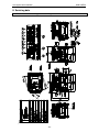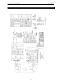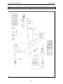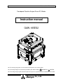
1
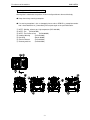
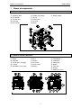
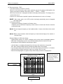
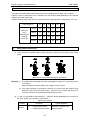
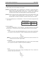
Reference No.
D18413 01204
Soundproof Gasoline Engine-Driven DC Welder
Instruction manual
GAW-185ES2
For ensuring safety, make sure to read this manual prior to use of the machine.
For ensuring safety, be sure to observe precautions given under headings
DANGER and
CAUTION.
For ensuring safety, keep this manual in a place of easy access, to permit reference to it whenever it is needed.
Denyo
Co., Ltd.
Thank you very much for your recent selection of a Denyo product.
This is a noise isolated engine welder & generator combined machine (hereinafter called "machine").
(See Page 40 for the specification.)
For handling of the machine and for working with the welder and generator functions of the machine,
observe applicable laws (Electricity Enterprises Law, Electric Engineering Technicians Law,
Occupational Health and Safety Law, Fire Services Act, Noise Control Law, etc.) as well as their
relevant laws and regulations.
This machine falls into the category of mobile electric works specified in the Electricity Enterprises
Law. It is necessary to carry out its handling, reporting and others in accordance with its relevant
laws and regulations.
This instruction manual …
This instruction manual explains correct handling method, simple inspection and care of the machine,
for permitting safe operation of the machine and for fully exhibiting the machine performance.
For ensuring safety, it is essential that qualified persons or those who understand welders and who
have knowledge and skill to safely handle welders implement installation, inspection, maintenance
and repair to the machine.
Erroneous handling of the machine may lead to serious injury or even loss of life.
Make sure to carefully read this manual and fully understand its contents before use
of the machine.
If you lend the machine to somebody else or allow such a person to use the machine, make sure to
explain the machine handling method and instruct him to read this “Instruction manual” before use of
the machine.
See the covenant for product warranty attached hereto regarding product warranty.
Keep this manual in a fixed place of easy access that permits reference to it whenever it is needed.
See the engine instruction manual (separate volume) for handling, maintenance and others of the
engine. For matters that are described in both of this manual and the engine instruction manual,
observe instructions given in this manual.
If this machine is mounted on a vehicle, it is not permitted to cause the vehicle to travel in the state
where this machine is running.
If you lose this instruction manual or if this instruction manual becomes illegible because of
contamination or the like, give us an order for a new instruction manual.
There is a possibility where the contents of this manual do not meet your machine due to changes to
the specification.
Enter the name of the sales representative, workshop for servicing and serial number of the machine
in the applicable columns appearing below upon purchase of the machine.
“The contact for inquiries is shown on the back cover of this instruction manual.”
If you any doubt arises or if you want to learn more about
maintenance of the machine, please do not hesitate to contact us.
When you contact us for an inquiry, please give us the type and
serial number of the machine.
The serial number is stamped on the main nameplate.
Window for contact:
In-charge sales office:
Workshop for servicing:
Your machine is …
型 式
GAW-185ES2
製 造
番 号
です。
Contents
For safe use of the machine
1. Names of component
Knowledge to be acquired before use of the machine .... 8
1-1 External appearances and names of components ..................................................................... 8
1-2 Names of internal components (Control Panel / Left Side ) ....................................................... 9
1-3 Names of internal components ................................................................................................... 9
1-4 Operation panel and names of components ............................................................................. 10
1-5 Digital panel ............................................................................................................................. 10
2. Conveyance and installation
For conveyance and installation of the machine .......... 12
2-1 Precautions for conveyance of the machine ............................................................................. 12
2-2 Precautions for installation of the machine ............................................................................... 13
3. Operation
For running the machine ............................................... 14
3-1 Pre-operational inspection ........................................................................................................ 17
3-2 Startup and running ................................................................................................................... 17
3-3 Stopping .................................................................................................................................... 18
3-4 After stopping ............................................................................................................................ 19
3-5 Protective devices ..................................................................................................................... 19
4. Welder operation
For working with the machine .................................. 20
4-1 Warning on matters to be observed prior to operation ............................................................. 20
4-2 Selection of welding cable......................................................................................................... 22
4-3 Welding cable and polarities ................................................................................................... 22
4-4 Adjustment of welding current ................................................................................................... 23
4-5 Slow down unit .......................................................................................................................... 23
4-6 Duty cycle .................................................................................................................................. 24
4-7 Regarding Stick welding work ................................................................................................... 24
4-8 Voltage reduction ....................................................................................................................... 25
4-9 Regarding AC power supply...................................................................................................... 25
4-10 Simultaneous use of welding power supply and AC power supply ......................................... 27
5. Periodic inspection and maintenance
For keeping the machine is a good order ...... 28
5-1 General inspection and maintenance prior to operation ........................................................... 30
5-2 Initial 20 hour inspection and maintenance .............................................................................. 30
5-3 Inspection and maintenance of once every 50 hours ............................................................... 31
5-4 Inspection and maintenance of once every 100 hours ............................................................. 31
5-5 Inspection and maintenance of once every 200 hours ............................................................. 32
5-6 Inspection and maintenance of once every 300 hours ............................................................. 33
5-7 Inspection and maintenance of once every 500 hours ............................................................. 33
5-8 Inspection and maintenance of once every 1,000 hours .......................................................... 34
5-9 Other inspection and maintenance ........................................................................................... 34
6. Troubleshooting
If the machine malfunctions............................................. 36
6-1 Engine malfunction and action to be taken ............................................................................... 36
6-2 Troubleshooting chart ................................................................................................................ 37
7. Long-term storage of the machine Care prior to storage of the machine for a long time ... 38
8. Servicing data
Data for servicing .......................................................... 39
8-1 External dimensions and appearance drawing ......................................................................... 39
8-2 Specification .............................................................................................................................. 40
8-3 Generator Wiring Diagram ........................................................................................................ 41
8-4 Engine Wiring Diagram ............................................................................................................. 42
8-5 Attachment ................................................................................................................................ 43
-1-
For safe use of the machine
GAW-185ES2
For safe use of the machine
Although the machine has been designed and produced with safety fully taken into account, it is
essential to observe the precautions given in this instruction manual in the use of the machine.
Death or serious injury may arise, if the machine is used with these precautions ignored.
Safety precautions are described in this manual as ranked using signal words indicated below.
DANGER:
Death or serious injury may arise, if the machine is erroneously handled.
CAUTION:
Personal injury of either medium or minor extent as well as damage to
properties may occur, if the machine is erroneously handled.
[Caution] :
Attention is required for permitting the machine to work efficiently and for an
extended period of time.
Even a matter described under the heading of
depending on the circumstances.
sure to observe them.
CAUTION may lead to serious results
All of these precautions describe important matters.
Make
•
Do not modify the machine without our permission.
functions and lifetime may result.
•
The warranty expires if the machine is modified without our permission, if the machine is used
in a manner that is different from what are described in the instruction manual or if any
component of the machine is replaced with other than genuine parts.
-2-
Safety may be destroyed and drop in
For safe use of the machine
GAW-185ES2
Mounting position of the warning nameplate
Warning label is attached to the position shown in the figure below to the machine body.
● Keep clean always warning nameplate.
● If a warning nameplate is lost or damaged, please order to DENYO by nameplate number
that is described below in () immediately. Please paste again to the specified location.
①
②
③
④
⑤
⑥
⑦
NOTE : Welding, exhaust gas, high temperature (D1510 0190A)
NOTE : Fire
(D1520 0190A)
NOTE : The fire due to fuel
(D1520 0080A)
Handling Warning
(D1510 0180A)
Ban lifting
(B9121 0020B)
Electrical Hazard
(D1510 0210A)
Runaway machine
(D1520 0150A)
-3-
For safe use of the machine
GAW-185ES2
DANGER: Electric shock
• Never touch electrical components such as output terminal and internal
wiring while the machine is running. For cable connection or for
inspection and maintenance of the machine, be sure to turn OFF the
circuit breaker and stop the engine, before starting such a work.
• When the machine or your body is wet, it is extremely dangerous.
Never touch the machine in such a state.
Electric shock that leads to death may arise, if the above
precautions are neglected.
DANGER: Poisoning caused by exhaust gas
• The exhaust gas from the engine contains substances that are
hazardous to human bodies.
Do not run the machine in a place of inferior ventilation such as tunnel
and indoors.
If it is necessary to run the machine in such a place, provide sufficient
ventilation using ventilating equipment or the like.
Furthermore, never direct the exhaust to passers, private homes and
others.
Serious injury or death may arise due to oxygen deficiency or toxic
gas, if the above precautions are neglected.
DANGER: Personal injury
• There are components rotating at high speed in the machine.
• Make sure to stop the engine, before starting maintenance and
inspection of the machine.
Personal injury may arise due to roll-in of your hands by rotating
components, if you fail to observe the precautions given above.
CAUTION: Fire
• Fuel and oil are combustible materials. Never bring any fire close to
the machine. Do not use the machine in a place where the machine is
exposed to sparks of welding or of a sander. Do not perform fueling
while you are smoking or while the machine is running.
• If the fuel or oil has spilt, fully wipe it off.
Ignition or kindling may occur, a fire may arise and burn injury may
result, if you fail to observe the precautions given above.
CAUTION: Eye deficiency
• Always use a helmet and a hand shield for execution of welding work, for
protection of eyes against harsh light and for protection of face and neck
against the radiant energy directly irradiated from the arc.
Eye deficiency will occur if welding work is executed with naked
eyes.
-4-
For safe use of the machine
GAW-185ES2
CAUTION: Burn injury
Never open the following places while the machine is running and also
immediately after termination of running.
(1) Radiator water filler cap
If the water filler cap is opened while the machine is running, steam or
hot water will jet out, and is extremely dangerous. Therefore, never
open the water filler cap while the machine is running.
Wait for at least 10 minutes after termination of running, before opening
the cap.
Furthermore, wear safety glasses and gloves, space your face away
from the cap, fit thick rag on the cap and slowly turn the cap to relieve
the pressure in the radiator before removing the cap.
(2) Never touch any high temperature portion.
Never touch the tail pipe, exhaust pipe and others, which are of high
temperature while the machine is running and also immediately after
termination of running.
Never touch the tail pipe, exhaust pipe and others, which are of
high temperature while the machine is running and also
immediately after termination of running.
Burn injury will occur to your hands, if the above precautions are
neglected.
CAUTION: Removal
(1) Falling during hoisting
• Use the lifting lug located at the center of the roof panel for hoisting
the machine. Furthermore, do not walk in to the space underneath
the machine in the hoisted state.
• Do not hoist the machine by the handle (rope fitting).
The handle will come off and the machine will fall if the machine
is hoisted by the handle.
(2) Falling during conveyance
• For conveyance of the machine on a truck or the like, fix two handles
using ropes or the like so that the machine will not move out of the
position.
• In case the machine is provided with wheels, positively lock the
wheels.
The machine will fall, if the above precautions are neglected.
Handle (rope fitting)
Lifting lug
Fix using ropes
Wheel
stoppers
CAUTION: Precautions on piling
• Assure that bonnets are free of damage and that bolts are free of looseness and miss-out, before
piling of machines.
• Place machines in horizontal positions on a solid ground that bears the weight of piled machines.
Piling should not exceed two tiers.
• Locate square timbers between tiers, and equally locate machines on these timbers. Moreover,
take appropriate measures for preventing horizontal displacement and falling that may be caused
by earthquake.
Erroneous piling may result in occurrence of collapse and falling troubles.
-5-
For safe use of the machine
GAW-185ES2
CAUTION: Casualty caused by battery
(1) Casualty caused by battery electrolyte
Be careful so as not to allow entry of battery electrolyte (dilute sulfuric acid) into eyes and not to
allow its attachment to the skin or clothes. If it entered eyes or attached to the skin, immediately
wash it off using plenty of water. In case of entry to eyes, submit to medical treatment.
Casualty to eyes and burn may result otherwise.
(2) Explosion caused by battery's flammable gases
The battery produces flammable gases. Therefore, be careful not to allow sparking from the
battery and not to bring any fire such as cigarette close to the battery.
Ignition and explosion may arise otherwise.
CAUTION: Wheel stoppers
• Use the machine in a level position on a solid ground.
If the machine is used on a slope under unavoidable circumstances, the
tolerance in the gradient is ±5° on each of longitudinal and lateral
directions.
• Make sure to lock wheels using wheel stoppers, except the occasion of
removal.
The machine may begin to move and run away, unless wheel
stoppers are fitted.
CAUTION: No connection to indoor wiring
• Never connect the AC power supply of the machine to any
indoor wiring.
• Connection to indoor wiring violates a law, and in addition,
may cause damage to both of the indoor wiring and the
machine.
CAUTION : No use in the rain
• Failure may arise due to wetting of the machine and electrical
components with rainwater. Do not use the machine in the
rain.
• Avoid water washing of the machine interior because of the
same reason.
-6-
Names of components
GAW-185ES2
1. Names of components
1-1 External appearances and names of components
①
②
③
④
⑤
Operation panel
Fuel Gauge
Fuel filler port
Lifting lug
Door handle
⑥
⑦
⑧
⑨
⑩
Handle (rope fitting)
Air inlet
Exhaust port
Air outlet
Wheel
⑪ Wheel stopper
Fuse
Reactor
Air cleaner
Recoil starter
Battery
⑪
⑫
⑬
⑭
⑮
⑯
⑰
1-2 Names of internal components
①
②
③
④
⑤
Engine
Generator
Oil filler port / Oil gauge
Oil drain
50Hz/60Hz select switch
⑥
⑦
⑧
⑨
⑩
Fuel Strainer
Carburetor
Spark Plug
Muffler
Fuel tank
Reactor
Muffler tail screen
14
13
15
17
12
12
16
-7-
10
11
Names of components
GAW-185ES2
1-3 Operation panel and names of components
No.
1
2
3
4
5
6
7
8
9
10
11
Name
*Digital monitor (*Model GAW-150ES2D only)
Welding current regulator
Arc force regulator
Voltage reduction device switch
AC Power output switch
Starter switch
Choke knob
Slow down switch
Welding output terminal
Single phase AC power output terminal
Single phase AC power output receptacle
-8-
Names of components
GAW-185ES2
1-4 Digital display monitor
①Welding current meter
②Set / actual current indicator
③ODO meter (section hour meter function)
④Display switching button
⑤Frequency indicator
(1) Welding current meter
・Welding current meter displays the actual current value and the current setting of the welding output.
Welding current meter displays the actual current value during welding. The welding current meter
displays the setting value under welding stop. The welding current is adjusted by turning the knob of
the welding current regulator.
・If the protective device of the machine is operated during operation, display of welding current meter
will switch to abnormal Symbol.
In that case, please identify the abnormal portion from Symbol. And, check and maintenance.
(2) ODO meter(ODO)
・This will display the accumulated operating time of the machine. Hour meter will start the
integration when the starter switch set to the "driving" position. Clock mark of the display unit
blinks during integration.
[Note]:When operating on without battery, hour meter counts the operating time from after the
engine is started.
[Note]:If you do not use the welder a long period of time, the internal battery of the digital display
monitor is exhausted. And, it may be integrated time meter stopped does not display.
Accumulated time meter is even no longer displayed, the integration time is not reset.
In this case, when the starter switch set to the "operation", it displays the hour meter by
using a power from battery. Internal battery for the monitor is charged with be operated to
start the engine.
-9-
Names of components
GAW-185ES2
(3) Time interval meter(TRIP)
・Time interval meter is built with "A" and "B".
When it is in the "ON" position starter switch, each time you press the display switching button, the
display screen will be switched in the order of "ODO" → "TRIP A" → "TRIP B".
When each interval time is displayed, hold down the display switching button. The display time is
reset and return to 0.
・Please use as a time meter of periodic inspection and maintenance for such as oil change.
[ NOTE]
]:When starter switch is the "OFF" position, the display automatically return to Integrated
time meter (ODO).
(4) Frequency indicator
・It displays the frequency of output for AC power source.
Frequency can be switched at a frequency selector switch on the left side of the door inside the
control panel under.
[ Note]
]:Do not change the frequency on the loaded condition. It causes of the failure of the control
unit.
[ Note]
]:Before using the welder, check the frequency of load side and display of the machine. it
should be same.
(5)Internal Battery for ODO meter display
・Digital display monitor has a built-in charging circuit and the internal rechargeable batteries.
ODO meter is displayed by a power source of internal battery when the machine will stop.
And charges the internal battery by operating the engine.
・Internal battery is completely discharged If you do not use the machine for a long period.
Then, takes a while the battery will be activated, and ODO meter will not display.
If you charge the battery about 30 minutes, then ODO meter displays 30 minutes or so. However,
it will be possible to display more than 10 days if you charge 3 hours or more.
Refer the following diagram as a guide for day number display and time of charging hours.
Diagram for number of
完全放電後バックアップ電池の
充電所要時間と表示日数の関係
displayed days and the time
required for charging the
100
90
backup battery completely
表示日数
discharged after.
80
Day number display (days)
表示日数(日)
70
60
50
40
30
20
10
0
0
2
4
6
8
10 12 14 16
充電時間(hr)
Charging hours (hours)
- 10 -
18
20
22
24
Periodic inspection and maintenance
GAW-185ES2
2. Conveyance and installation
2-1 Precautions for conveyance of the machine
CAUTION: Removal
(1) Falling during hoisting
• Use the lifting lug located at the center of the roof panel for hoisting
the machine. Furthermore, do not walk in to the space underneath
the machine in the hoisted state.
• Do not hoist the machine by the handle (rope fitting).
The handle will come off and the machine will fall if the machine
is hoisted by the handle.
(2) Falling during conveyance
• For conveyance of the machine on a truck or the like, fix two handles
using ropes or the like so that the machine will not move out of the
position.
• In case the machine is provided with wheels, positively lock the
wheels.
The machine will fall, if the above precautions are neglected.
Handle (rope fitting)
Lifting lug
Fix using ropes
Wheel
stoppers
CAUTION: Wheel stoppers
• Use the machine in a level position on a solid ground.
If the machine is used on a slope under unavoidable circumstances, the
tolerance in the gradient is ±5° on each of longitudinal and lateral
directions.
• Make sure to lock wheels using wheel stoppers, except the occasion of
removal.
The machine may begin to move and run away, unless wheel
stoppers are fitted.
For conveyance of the machine from the field of work, be sure to load the machine on a truck or the like.
Dimensions of the machine are as follows.
Length
Width
(mm)
(mm)
730
555
Height
(mm)
675
Dry mass
(kg)
105
Fully equipped
mass (kg)
118
Dry mass: Mass without cooling water, lubricating oil and fuel
Fully equipped mass: Mass with cooling water, lubricating oil, battery 1electolyte (to the specified level)
and fuel (full tank)
See “External dimensions and appearance drawing” for details.
Wheel Stopper
Wheel
• The machine equipped wheel stopper and operate Lock/Off by
the lever
• Make sure to wheel stopper lock position, when operate the
machine and conveyance of the machine on a truck
• When move the machine by wheel, make sure to wheel stopper
off position.
- 28 -
Stopper
Lock
Lever
OFF
Periodic inspection and maintenance
GAW-185ES2
2-2 Precautions for installation of the machine
DANGER: Poisoning caused by exhaust gas
• The exhaust gas from the engine contains substances that are
hazardous to human bodies.
Do not run the machine in a place of inferior ventilation such as tunnel
and indoors.
If it is necessary to run the machine in such a place, provide sufficient
ventilation using ventilating equipment or the like.
Furthermore, never direct the exhaust to passers, private homes and
others.
Serious injury or death may arise due to oxygen deficiency or toxic
gas, if the above precautions are neglected.
Select a place that satisfies the following conditions for installation of the machine.
(a) Select a level place. If the machine is used on a slope under unavoidable circumstances, the
allowable inclination angle is ±5° in both of longitudinal and lateral directions. Apply
appropriate slip stoppers. Fit wheel stoppers, if the machine is equipped with wheels.
[Caution]: If inflammable substances (such as paper dust and wood chips) and/or dangerous
substances (such as oil and Output name powder) are found in the vicinity, remove them before
starting welding work.
[Caution]: Provide protection screens or the like around the place of welding work, for preventing
scattering of arc light and spatter.
(b) Avoid a place of high temperature and high humidity.
(c) Avoid a place of ambient temperature over 40°C.
(d) Avoid a dusty place and place where noxious gases or explosive gases are present.
Furthermore, space the machine from inflammable goods in the surroundings.
(e) Locate the machine in a place where welding spatter and grinder (sander) sparks enter the air
inlet and outlet of the machine.
(f) This machine cannot be piled in tiers, as it is equipped with wheels.
(g) Never run this machine while the vehicle, on which this machine is located, is traveling or while
the machine is suspended in the air.
(h) For the bonnet air intake, provide a space of at least 50 cm from the wall face or other
obstacles.
[Caution]: Overheat may arise, if the machine is run in a small space. If it is necessary to run the
machine under such a condition that the clearance from any side of the machine is less than 50
cm, please consult with us.
[Prohibited matters]
(1) No connection to indoor wiring
• Never connect the AC power supply of the machine to any
indoor wiring.
• Connection to indoor wiring violates a law, and in addition,
may cause damage to both of the indoor wiring and the
machine.
(2) No use in the rain
• Failure may arise due to wetting of the machine and electrical
components with rainwater. Do not use the machine in the
rain.
• Avoid water washing of the machine interior because of the
same reason.
- 29 -
Periodic inspection and maintenance
GAW-185ES2
3. Operation
3-1
Pre-operational inspection
DANGER: Personal injury
▪ There are components rotating at high speed in the welder.
▪ Make sure to stop the engine, before starting maintenance and
inspection of the welder.
Personal injury may arise due to roll-in of your hands by rotating
components, if you fail to observe the precautions given above.
Carry out inspection described below prior to operation.
(1) Check of engine oil level
Fully insert the engine oil level gauge, and check if the oil level is within the range of “H”" level and
“L” level on the level gauge. Check the oil for contamination at the same time.
Replenish oil If the oil level is less than the “L” level (lower limit).
[Caution]:The oil level should not be higher than the “H” level (upper limit). Damage to engine
cylinder interior may occur otherwise.
Regarding engine oil
Engine oil exerts major influence over the engine performance, startability, lifetime and others.
Therefore, select engine oil of viscosity that is most appropriate for the atmospheric temperature of
the place of use.
(a) Use engine oil of CC class or higher of API service classification.
(b) Oil for summer (SAE30) is recommended for use in summer, and oil for winter (SAE20) is
recommended for use in winter. In addition, oil for all seasons (SAE10W-30), the viscosity of
which hardly changes by temperature, is recommended for use throughout the year.
Select appropriate engine oil in accordance with the lower right table.
(c) The oil volume required for oil change is as follows.
SAE viscosity and applicable temperature range
Gross engine oil volume
Fresh air temperature (°C)
1.2 L
H
L
- 30 -
Periodic inspection and maintenance
GAW-185ES2
[Caution]: Do not mix engine oil of different kinds. It is because properties of the engine oil may
become inferior, if engine oil of different kinds is mixed together.
- 31 -
Periodic inspection and maintenance
GAW-185ES2
(2) Check of fuel level
CAUTION: Fire
▪ Fuel and oil are combustible materials. Never bring any fire close to
the welder. Do not use the welder in a place where the welder
exposed to sparks of welding or of a sander. Do not perform fueling
while you are smoking or while the welder is running.
▪ If the fuel or oil has spilt, fully wipe it off.
Ignition or kindling may occur, a fire may arise and burn injury
may result, if you fail to observe the precautions given above.
Check, by observing the Fuel gauge.
If the fuel is low, fill the fuel tank with clean and fresh NON-LEAD gasoline. Do not over fill the fuel tank.
The fuel tank cap must be closed tightly after filling.
If the fuel is contaminated, close the fuel cock and drain to the receiver pan from the cup / tank.
Regarding fuel
(a) Use NON-LEAD gasoline. Do not use any alternative fuel
because its quality is not known, it exerts adverse effect over the
engine.
(b) Do not over fill red marking at fuel filler port filter.
[Caution]: If the fuel or oil has spilt, fully wipe it off.
Be cautious of the fuel!!
▪ Never fill the fuel tank while the engine is running or in the dark. Gasoline soillage on a hot engine
can cause a fire or an explosion. If gasoline spillage occurs, wipe up the spilled gasoline completely
to prevent hazards.
- 32 -
Periodic inspection and maintenance
GAW-185ES2
(3) Open the fuel cock
(4) Check the spark plug
Do not touch the spark plug, cable and cap, while the engine is running.
Make sure to stop the engine, before check the spark plug and using a plug removal tool.
Fuel Filler Port
Red mark
Cap
Spark Plug
Gap
Filter
Fuel gauge
Gasket
Fuel Cock
Close
Open
(5) Check of pipe joints
Check pipe joints for looseness, oil leakage. Carry out repair or replacement, if any abnormality is
found.
(6) Check of wiring
Check wiring for loose connection and wear.
found.
Carry out repair or replacement, if any abnormality is
[Caution]: Do not run the welder in the state where the welder is covered with a sheet or in the state
where any article is placed on the exhaust hole or air outlet.
Moreover, make sure that the air intake hole is not plugged.
- 33 -
Periodic inspection and maintenance
GAW-185ES2
(7) Connection and check of battery cables
Connect battery cables in correct polarity. If connection is made in incorrect polarity (reversing of +
and -), electric components will be damaged, even if such an error occurred only for a short length
of time.
[Caution]: Connect battery cables in the state where the starter switch key is removed.
Applying small amount of grease to battery terminals will prevent corrosion to terminals.
Furthermore, firmly connect cables to terminals. If connection is insufficient, malfunction may arise
due to faulty contact, and troubles may result.
- 34 -
Periodic inspection and maintenance
3-2
GAW-185ES2
Startup and running
Make sure that no obstacle is located in the range of 1 m from the welder, and send a
signal to the people located around the welder, before starting the engine. Furthermore,
lock the engine while it is running, so that operation by anybody having no knowledge on the
welder or welder operating skill is disabled.
▪ Select the using frequency by the frequency select switch located inside the door.
[Caution]: Do not change the frequency, while the engine is running.
▪ Slow down switch “ ON “ position.
▪ Make sure the machine abnormality and close the door.
Fuel cock “Open”
Choke “CLOSE“
Starter switch “Run” to “Start”
If engine start is a cold weather, choke is
close position. Adjust the opening of the
choke knob according to operating
conditions. When the air temperature is
high, close the choke knob halfway or
open it all the way
Starter switch “Run” position
Choke “OPEN”
Warm-up (After the engine start, let the machine idle more than 5 minutes to warm-up )
[Caution]: If no ignition tone is produced even after turning the starter motor for about 10
seconds, it is essential to allow a pause time of at least 10 seconds in the state where the
starter switch is returned to the “STOP” position, before turning the starter motor again.
[Caution]: If the starter switch does not return to the position of the "operation"
automatically, please return to the "operation" manually. Could be damaged by the
starter motor continues around.
Choke
Open
Close
Push
Fuel cock
Slow down switch
Close
Open
Starter switch
Frequency select
switch
- 35 -
Periodic inspection and maintenance
GAW-185ES2
Push
Push
- 36 -
Periodic inspection and maintenance
GAW-185ES2
[Caution]: Do not turn the starter switch while the engine is running.
▪ If abnormal vibration or abnormal noise was observed, stop the engine and carry out inspection.
Moreover, check for emission of black smoke or white smoke.
▪ Keep all the doors closed and keep the side door locked during running.
If any door is kept open, the welder may be damaged due to inclusion of foreign matters. In
addition, cooling conditions may become inferior due to changes in the airflow, and troubles may
result.
▪ Watch meters on the operation panel during running, and make sure that normal ranges are not
exceeded and no warning lamp is lit. If any warning lamp lights up, immediately stop the engine
and check the abnormal point.
▪ Make sure that the cumulative hour meter is working during running.
It starts working upon start-up of the engine.
▪ After the engine starts, let the machine idle for more than 5minutes to warm-up.
(1) Do not turn the starter (switch “Start” position) over than 10seconds.
If the machine fails to start despite repeating the starting procedure, there is obviously some
problem with the machine.
Therefore a thorough check is required (e.g. : Fuel has run out, forgetting to turn the fuel cock to the
open position and battery leakage)
(2) Recoil start
If the machine is could not to start by starter switch caused by battery leakage etc., Can be start by
the recoil start.
If using recoil start, the starter switch to “Run” position.
▪ Pull out the recoil starter knob slowly, make sure engaged latch of starter (pull the rope feel heavy)
and pull out strongly.
▪ After the engine is started, return to the recoil starter knob slowly.
(3) After the engine starts, let the machine idle for more than 5minutes to warm-up.
(4) If abnormal vibration or abnormal noise was observed, stop the engine and carry out inspection.
Moreover, check for emission of black smoke or white smoke.
(5) Keep all the doors closed and keep the side door locked during running. If any door is kept open, the
welder may be damaged due to inclusion of foreign matters. In addition, cooling conditions may
become inferior due to changes in the airflow, and troubles may result.
(6) Make sure that the cumulative hour meter is working during running. It starts working upon start-up
of the engine.
- 37 -
Periodic inspection and maintenance
3-3
GAW-185ES2
Stopping
(1) The engine revolution drops when the slow down switch is push to the “ON” position.
Continue cool-down running for about 5 minutes in this state.
(2) Stop the engine by turning the starter switch to the “STOP” position.
(3) If the engine fails to stop even when starter switch is turned to the “STOP” position, use one out of
two methods indicated below for forcibly stopping the engine.
(4) After the engine has stopped. Turn the fuel cock to the “CLOSE” position and remove the key out of
the starter switch.
- 38 -
Periodic inspection and maintenance
3-4
GAW-185ES2
After stopping
(1) In case it is intended that the welder will not be used for a certain length of time, be sure to remove
the starter switch key, and keep it in the specified position with care exercised not to lose it.
(2) Turn the fuel filter cock to the “CLOSE” position.
(3) Disconnect the welding cable. Disconnect cables and plugs from AC power outlets.
(4) Keep refueling the fuel tank. If left in a state in which the fuel in the fuel tank is low, water droplets
adhering fuel is evaporated, water accumulates in the fuel tank.
(5) Check out the loose bolts and nuts. Be retightened if there is nuts and bolts that are loose.
(6) Upon confirmation of complete cool-down of the welder, cover up the welder with a sheet or the like
and store the welder in a place of little humidity. Do not leave the welder in open air.
- 39 -
Periodic inspection and maintenance
3-5
GAW-185ES2
Protective devices
The welder is equipped with protective devices indicated below that act against errors during running.
When any of these protective devices is activated, immediately stop running of the welder and carry out
troubleshooting of the abnormal point.
List of protective devices
Action
Welding out
Engine shut
AC output shut
down
down
Oil level drop
○
---
---
○
Control unit
input over
---
○
---
---
---
○
---
---
---
○
---
---
---
○
---
---
---
---
○
---
Item
put shut
down
Lamp
indication
voltage
AC output over
current
AC output over
voltage
AC control unit
high
temperature
Oil feed
Release automatically by
engine revolution slow.
AC power out put switch “OFF”
position.
AC power out put switch “OFF”
position.
AC power out put switch “OFF”
Welding control
unit high
Release of protecting
temperature
position and unit temprature
fall.
Release automatically by
temperature fall.
Note: In case of fuse blow, check the wiring for abnormality and check for entry of foreign matters, before
fuse replacement.
- 40 -
Periodic inspection and maintenance
GAW-185ES2
4. Welder operation
4-1
Warning on matters to be observed prior to operation
DANGER: Make sure to observe the following instructions for avoiding serious accidents
(1)
(2)
(3)
(4)
resulting in injury or death.
Observe laws and regulations and your in-house standards for working power sources on the
input side, setup of place of installation, handling of high-pressure gases, storage and piping,
storage of products after welding, disposal of waste and others.
Take measures to prevent people from entering improperly the section around the welder and the
welding work area.
If you use a pacemaker for your heart, do not enter the section around the welder and the welding
work area until your doctor permits it. A welder produces a magnetic field around the welder
while electric power is fed to it, and exerts adverse effect over the operation of your pacemaker.
To secure safety, it is necessary that qualified persons or those who fully understand the welder
execute installation, maintenance and inspection as well as repair to this welder.
DANGER: Make sure to observe the following instructions for avoiding electric shock.
(1)
(2)
(3)
(4)
(5)
(6)
(7)
(8)
▪ Fatal electrical stunning and burn may arise, if you touch any live part.
Do not touch any live part.
Do not use a cable of insufficient capacity, a damaged cable or a cable with exposed conductors.
Be sure to tighten and insulate each cable joint.
Do not use the welder in the state where the case or cover is removed from it.
Do not use broken or wet gloves. Always use dry insulating gloves.
Use a life rope in case of working in an overhead location.
Conduct periodic maintenance and inspection. If any damaged portion was found, repair it
before use.
Turn off the power for all the equipment when the welder is not used.
DANGER: Make sure to observe the following instructions for avoiding fire, explosion
and burst.
▪ Spatter and hot base metal immediately after welding may trigger fire.
▪ If there is any point of incomplete contact in the cable or in the current path on the
base metal side such as steel, fire may break out due to heat generation caused by
current conduction.
▪ A container for combustible substance such as gasoline may explode, if arcing
occurs to it.
▪ An enclosed tank or pipe may burst when it is welded.
(1) Remove combustible materials from the surrounding area, so that scattering spatter will not hit
combustible materials. If they cannot be removed, cover them up with incombustible covers.
(2) Do not perform welding in the vicinity of combustible gases.
(3) Do not bring hot base metal immediately after welding close to combustible materials.
- 41 -
Periodic inspection and maintenance
(4)
(5)
(6)
(7)
(8)
GAW-185ES2
For welding of the ceiling, floor, wall or the like, remove hidden combustible materials.
Be sure to tighten and insulate cable joints.
Connect the cable on the base metal side to as close as possible to the welding point.
Do not weld a gas pipe containing gas. Do not weld an enclosed tank or pipe.
Locate fire extinguishers near the welding work area for emergency use.
- 42 -
Periodic inspection and maintenance
CAUTION:
(1)
(2)
(3)
(4)
(5)
(6)
(2)
(3)
(4)
(5)
Wear protective equipment for protecting you and other people against
fumes and gases produced during welding.
▪ Health hazard may arise, if fumes and gases produced during welding is inhaled.
▪ Suffocation may occur due to shortage of air, if welding work is performed in a small
space.
Provide sufficient ventilation or use air breathing equipment or the like, for preventing gas
poisoning and suffocation, in a place specified in laws and regulations (Ordinance on Labor
Safety and Hygiene, Ordinance on Prevention of Anoxia).
Use local exhausting equipment specified in laws and regulations (Ordinance on Labor Safety
and Hygiene, Ordinance on Prevention of Dust Hazards) or use respiratory protective equipment,
for preventing dust hazards and poisoning caused by fumes or the like.
Provide sufficient ventilation or use respiratory protective equipment for welding in a small space.
In addition, execute works in such a place under the supervision of well-trained supervisors.
Do not perform welding work in a place near the area where degreasing, washing and or spraying
work is in progress. Noxious gases may be produced, if welding work is performed near such a
place.
For welding of coated steel products, be sure to provide sufficient ventilation or use respiratory
protective equipment. Noxious fumes and gases may be produced when coated steel products
are welded.
When welding work is performed at the bottom of a tank, boiler, ship bottom or the like, gases
such as carbonic acid gas and argon gas that are heavier than air will stay at the bottom.
Provide sufficient ventilation or use air breathing equipment or the like in such a place, for
preventing atmospheric hypoxia.
CAUTION:
(1)
GAW-185ES2
Wear protective equipment for you and other people against arc light,
scattering spatter, slag and noise produced during welding.
▪ Arc light may trigger inflammation to eyes and skin burn.
▪ Scattering spatter and slag may cause damage to eyes and burn.
▪ Noise may cause troubles in the acoustic sense.
For monitoring welding work or welding, use light shielding glasses of sufficient light shielding
performance or welding protective masks.
Use protective glasses for protection of eyes against spatter and slag.
Wear protective equipment such as welding leather gloves, long-sleeved clothes, leg covers and
leather aprons for execution of welding work.
Provide protective curtains around the welding work area, so as not to allow entry of arc light into
eyes of the people.
Wear noise protective equipment if the noise level is high.
- 43 -
Periodic inspection and maintenance
CAUTION:
GAW-185ES2
Examine the following matters for preventing electromagnetic hazards.
Furthermore, examine the following matters again if any electromagnetic
hazard occurs.
▪ Large current that rapidly changes during welding flows to the welder and weldment,
and it may hinder nearby equipment by electromagnetic noise.
(1) Do not share the ground for the base metal and welder with the ground for other equipment.
(2) Firmly close and fix all the doors and covers of the welding power supply unit.
(3) Minimize the length of the welding cable.
(4) Lay the base metal side cable, holder and torch side cable alongside to each other.
▪ Measures to be taken when any electromagnetic hazard occurs include the
following.
(1) Change the welder grounding point.
(2) Space the affected equipment apart from the welding power supply unit, cables and welding work
area.
(3) Apply electromagnetic shielding to the entire welding work area.
Please consult with us, if the problem of electromagnetic hazard is not solved even after taking
measures stated above.
- 44 -
Periodic inspection and maintenance
4-2
GAW-185ES2
Selection of welding cable
The longer the welding cable and the larger the current, a welding cable of larger size is required.
Prepare a cable of appropriate size as selected out of the following table depending on the required
welding current and cable length.
Relation between cable length and size (sectional area) for reducing cable's voltage drop to 4V or less
Cable length (m)
Cable size
(mm 2)
depending on
welding
current (A)
4-3
20
30
40
50
80
100
50 (A)
14
14
14
14
22
22
100 (A)
14
14
22
22
30
38
150 (A)
22
22
30
38
50
60
185 (A)
22
30
38
50
60
80
Welding Cable and Polarities
(a) Firmly connect the welding cable to output terminals located in the lower part of the control
panel.
Make sure to mount a terminal to the tip (connection).
[Caution] (1) The welder will be damaged, if the cable is damaged or if tightness of connecting screws
is insufficient.
Repair damage to the cable, and be sure to tighten connect screws.
(2) If any cable end lead is connected to a terminal in a circular form after stripping, heat
generation may arise due to faulty contact. Also burn to the insulator and short-circuit
caused by contact of the lead with the welder body may result.
(b) (+) and (-) are marked on output terminals. Select the polarity depending on the contents of
the work. Typical use of polarity is shown below.
Typical use of polarity
Polarity
Positive
Connection
Typical application
(+) ------- Ground (base metal)
(-) -------- Welding electrode holder
- 45 -
Welding of structural steel
and heavy plate
Periodic inspection and maintenance
Reversed
polarity
GAW-185ES2
(+) ------- Welding electrode holder
(-) -------- Ground (base metal)
- 46 -
Deposit welding, arc welding
of thin sheets, arc welding of
stainless steel, air gouging
Periodic inspection and maintenance
4-4
GAW-185ES2
Adjustment of welding current
(1) Adjust welding current with the welding current regulator.
[Caution]: If two different welders are run simultaneously as connected to a common base metal in
different polarity, the voltage between holders rises to a level produced by addition of
voltages from two welders and electric shock may arise. Therefore, such a situation that
one worker holds two holders of two different welders should be avoided absolutely.
[Caution]: When a common base metal is welded in different polarity using two different welders, make
sure to separately connect grounding cables on the base metal side. If a common
grounding cable is used and if its grounding is incomplete, troubles may arise to welders.
(2) The current regulating range is as indicated below. Select a current value that is appropriate for the
work contents.
Applicable electrode
Current range
30-185 A
Welding electrode
Ø2.0-Ø4.0
(3) Arc force regurator
This machine is equipped with an “ Arc force regurator ” , the welding characteristic can be sdjusted
with the function. It ‘s useful when you want to change welding characteristic for peculiar welding.
(a) HARD
Its short circuit current is about 100A added welding currnet. It’s easy to start arc and the power
of arc strong in this mode. Particulary it’s suitable for welding with high cellulostic welding rod.
[NOTE]: As it’s short circuit current is restricted by a limited circuit to to protect circuit board . The
maximum short circuit current is approx. 230A.
(b) STANDARD
Its short circuit current is about 50A added welding current. It’s easy to start arc and the stability
of arc is superior in this mode. It’s suitable for many kinds of weliding rod.
(c) SOFT
Its short circuit current is almost same as large as the welding current. The arc is stable in this
mode by its stable cyrrent characteristic.
- 47 -
Periodic inspection and maintenance
4-5
GAW-185ES2
Slow down unit
(1) This unit is provided for noise prevention and fuel saving during running without load. It executes
control as described below in the state where the slow down switch is “ON.”
1) When welding is suspended for a while in the state where the welder keeps running, the engine
revolution changes to a low level automatically (2500 min-1) after elapse of a fixed length of time
(about 9-10 seconds).
2) When the AC output and welding output are used.
(2) For normal use of the welder, set the slow down switch in the “ON” position.
(3) When it is necessary to pay particular attention to the bead external appearances and welding
defects, set the slow down switch in the “OFF” position.
- 48 -
Periodic inspection and maintenance
4-6
GAW-185ES2
Dutry cycle
No matter how tough a person may be, he will be exhausted if he keeps working without rest. This
welder is not of a design that withstands continuous use when it is used as a welder, from the viewpoints
of job contents and economy.
Duty cycle indicated below explains this situation. It is the same for manual welding.
10 minutes
* Usage rate represents the ratio of the load time in a 10-minute period. Usage
rate 50%, for instance, means no-load running for 5 minutes after load running
(welding) for 5 minutes.
[Caution]: Be careful so that overload will not occur, referring to the following table.
Relation between used current and Duty cycle
4-7
Duty Cycle (%)
100%
85%
70%
60%
50%
55%
40%
Used current (A)
120A
130A
140A
150A
160A
170A
170A
Regarding Stick welding work
CAUTION: Eye deficiency
▪ Always use a helmet and a hand shield for execution of welding work,
for protection of eyes against harsh light and for protection of face
and neck against the radiant energy directly irradiated from the arc.
Eye injury may result if welding work is executed with naked
eyes.
Lens brightness numbers for welding work
Welding work
Electrode size for covered arc welding
Ø1.6- Ø4.0
Ø5.0- Ø6.0
Ø8.0- Ø9.5
Brightness
number
10
12
14
[Caution]: If there is any flammable substance (such as paper dust and wood chips) and/or dangerous
articles (such as oil, grease and explosive) in the surroundings, remove them before starting
- 49 -
Periodic inspection and maintenance
GAW-185ES2
welding work.
[Caution]: Do not use this welder for any purpose other than welding.
4-8
Voltage reduction
(1) This unit is assist in the reduction of electrical shock to personnel involved in welding activities. It
reduces open circuit voltage to safe value before and after the welding operation.
(2) The voltage reduction switch in the “ON” position, welding no load voltage become below 27V.
Upon arc strike, normal selected voltage becomes available. Upon completion of welding, the open
circuit voltage is returned to a safe value.
(3) When it is necessary to pay particular attention to the bead external appearances and welding
defects, set the voltage reduction switch in the “OFF” position.
4-9
Regarding AC power supply
[Caution] :
[Caution] :
The welder will be damaged, if the cable is damaged or if tightness of connecting screws
is insufficient. Eliminate damage to the cable, and be sure to tighten connecting screws.
If any cable end lead is connected to a terminal in a circular form after stripping, heat
generation may arise due to faulty contact. Also burn to the insulator and short-circuit
caused by contact of the lead with the welder body may result.
(1) Switching between 50Hz and 60Hz
[Caution] : Do not frequency switching when use the AC output
operation..
(2) Do not execute load “ON/OFF” by connection/discontinuation of
the power plug.
ON
(3) When the AC power supply is used, turn “OFF” the AC power
output switch before making connection to the object equipment.
The capacity of each power receptacle is 15A and output
terminal 30A. Up to 30A may be used in the total of power
outlets. Connect load to them so that equal loads are applied to
these two power outlets.
OFF
15A
30A
15A
Total 30A
(4) Please observe the current capacity of the output receptacles.
Outlet to overheat when the octopus wiring to concentrate on one It becomes the cause of
burnout. Please use it is distributed to the other outlets.
(5) Grounding of load equipment
Ground the case of each load equipment like the case of the generator.
(6) Grounding of case grounding terminal
- 50 -
Periodic inspection and maintenance
GAW-185ES2
Select a grounding rod and perform grounding work so that the grounding resistance is no higher
than 100Ω by Class D grounding work specified in the Electrical Equipment Technical Specification.
Select a grounding lead wire of size that corresponds to the generator capacity based on the
Electrical Equipment Technical Specification.
4-10
Simultaneous use of welding power supply and AC power supply
Do not allow over loading when AC and DC are used simultaneously.
AC power supplies are used concurrently
Welding Rod
0
AC power supply capacity allowable
for simultaneous use
3.0kVA
Ø2.0 (50A)
2.0kVA
Ø2.6 (80A)
1.4kVA
Ø3.2 (120A)
1.0kVA
Ø4.0 (150A)
0.5kVA
Simultaneous use of welding power supply and AC power supply should be avoided, in case
particular importance is attached to bead external appearances and welding defects.
- 51 -
Periodic inspection and maintenance
GAW-185ES2
5. Periodic inspection and maintenance
DANGER: Personal injury
• There are components rotating at high speed in the machine.
• Make sure to stop the engine, before starting maintenance and
inspection of the machine.
Personal injury may arise due to roll-in of your hands by rotating
components, if you fail to observe the precautions given above.
CAUTION: Burn injury
Never open the following places while the machine is running and also
immediately after termination of running.
(1) Radiator water filler cap
If the water filler cap is opened while the machine is running, steam or
hot water will jet out, and is extremely dangerous. Therefore, never
open the water filler cap while the machine is running.
Wait for at least 10 minutes after termination of running, before opening
the cap.
Furthermore, wear safety glasses and gloves, space your face away
from the cap, fit thick rag on the cap and slowly turn the cap to relieve
the pressure in the radiator before removing the cap.
(2) Never touch any high temperature portion.
Never touch the tail pipe, exhaust pipe and others, which are of high
temperature while the machine is running and also immediately after
termination of running.
Burn injury will occur to your hands, if the above precautions are
neglected.
CAUTION: Casualty caused by battery
(1) Casualty caused by battery electrolyte
Be careful so as not to allow entry of battery electrolyte (dilute sulfuric acid) into eyes and not to
allow its attachment to the skin or clothes. If it entered eyes or attached to the skin, immediately
wash it off using plenty of water. In case of entry to eyes, submit to medical treatment.
Casualty to eyes and burn may result otherwise.
(2) Explosion caused by battery's flammable gases
The battery produces flammable gases. Therefore, be careful not to allow sparking from the
battery and not to bring any fire such as cigarette close to the battery.
Ignition and explosion may arise otherwise.
CAUTION: CAUTION: Disposal of waste liquid and others
(1) Observe regulations for waste treatment for disposal of oil, fuel, cooling water, hydraulic fluid,
solvent, filter, battery and other hazardous substances and waste liquid.
(2) Do not carelessly dispose any waste liquid drained out of this machine. It will destroy the
environment.
Discharge the waste liquid to a container, and apply appropriate waste treatment to it as industrial
waste based on Water Pollution Prevention Law, Soil Pollution Prevention Law, Air Pollution
Prevention Law and others.
Discharge of untreated effluent to the ground surface and disposal to river, lake or the sea are
forbidden.
- 52 -
Periodic inspection and maintenance
GAW-185ES2
5-1 General inspection and maintenance prior to Operation
(1) Check for loose, missing, damaged bolt/nuts or other fasteners.
(2) Check for engine oil level and fill.
(3) Check for fuel or oil leakage.
5-2 Initial 20-hour inspection and maintenance
(1) Change of engine oil
Engine oil be replaced at an early period of either one month or after 20 hours after the start of
operations.
1) Remove the engine oil drain plug, and fully discharge the engine oil.
Smooth discharge is permitted, if the work is performed while the engine is still warm.
2) Feed fresh engine oil through the oil filler port, up to the “H” level (upper limit) marked on the
engine oil level gauge.
3) Run the engine for a while, assure that no oil leakage is observed, and then stop the engine.
Check the engine oil level about 10 minutes later. If the oil level is lower than the specified level,
replenish oil.
Oil filling
Do not thrust the dipstick
Oil drain
Use box wrench
(14mm)
Battery
Air Cleaner
Element
Fuel strainer
Cover
Mesh
Packin
Nut
Cup
- 53 -
Periodic inspection and maintenance
GAW-185ES2
5-3 Inspection and maintenance of once every 50 hours
(1) Cleaning of air cleaner element
Remove the cover and element. Wash the element in a non-flammable or high point solvent and
squeeze thoroughly. Soak the element in the clean mixed oil and squeeze out of the excess oil,
then reinstall the element and cover.
【Mixed oil ratio, kerosene 3 : engine oil 1】
Air cleaner element
Part No.: 06020 46697
[Caution]: Check the element for damage at the time of cleaning, and replace it if damaged.
Positively mount the element in such a manner that no air leakage will occur, with attention paid not
(2) Check hose joints for looseness, damage. Carry out repair or replacement, if any
abnormality is found.
(3) Check wiring and connector for looseness, damage. Carry out repair or replacement, if any
abnormality is found.
5-4 Inspection and maintenance of once every 100 hours
(1) Change of engine oil
(2) Cleaning of Fuel strainer
Remove the cup of the fuel strainer, cleaning inside the cup and strainer.
When remove the cup to be check for damage, oil leakage. Carry out repair or replacement, if any
abnormality is found.
5-5 Inspection and maintenance of once every 200 hours
WARNING: High voltage and Electrical Hazard
・Do not touch the electrical component such as internal wiring and output
Terminal during the operation. Need to stop the operation always when
do the maintenance and inspection of the connection cable.
・Do not touch the machine when the body and the machine is wet
because it is very dangerous.
If you neglect the caution death or serious fatal accident occur .
(1) Check and cleaning of spark plug
Remove carbon build up on the spark plug with wire brush. Set the spark plug gap to 0.6-0.7mm.
Tighten with a spark plug wrench.
Spark plug maker : NGK
Model No.: BR6HS
(2) Measurement of insulation resistance
1) Measure the insulation resistance every 200 hours or per month by the insulation resistance
- 54 -
Periodic inspection and maintenance
GAW-185ES2
tester of 500V, to check whether there is more than 1MΩ.
Do not use the insulation resistance by the insulation resistance tester that exceeds 500V.
There is a possibility that the control device will be broken if you use it.
If you need to use the insulation resistance tester that exceeds 500V, take off all connector which is
connecting to control unit.
2) Measuring methods
Take off a load side electric wire of the output terminal and make the AC output "ON".
Measure the insulation resistance between each welding output terminal bolt, interchange output
terminal and outlet and the bonnet.
Bonnet
5-6 Inspection and maintenance of once every 300 hours
(1) Check and alignment of engine intake, exhaust vale
(as brought to a specified servicing workshop)
5-7 Inspection and maintenance of once every 500 hours
(1) Check of battery voltage and charge
(2) Tightening engine head (as brought to a specified servicing workshop)
(3) Check and cleaning of carburetor (as brought to a specified servicing workshop)
(4) Check and alignment intake, exhaust vale (as brought to a specified servicing workshop)
5-8 Inspection and maintenance of once every 1000 hours
(1) Replace the piston ring (as brought to a specified servicing workshop)
5-9 Other inspection and maintenance
(1) Replacement of fuel hose (as brought to a specified servicing workshop)
Replace fuel hose if the fuel hose has become hard or if the fuel hose has deteriorated.
(Fuel hose replace every 2yeras)
(2) Replacement of noise absorbing materials (as brought to a specified servicing workshop)
Replace noise absorbing materials, if they are excessively contaminated or if exfoliation (attachment
of fats) is observed.
- 55 -
Long-term storage of the machine
GAW-1850ES2
6. Troubleshooting
Causes for troubles and actions to be taken against them
Almost all the troubles can be prevented by proper handling and by implementation of inspection and
maintenance. If any trouble arises, take actions with reference made to the following description.
6-1 Engine malfunction and actions to be taken
If the engine malfunctions, take appropriate actions based on the following chart.
(See the instruction manual for the engine for details.)
Trouble phenomenon
The engine hardly
starts.
The engine output is
insufficient.
The engine halted all
of a sudden.
The color of the
exhaust gas is inferior.
Probable cause
Fuel is not flowing.
Fuel is not coming to
Carburetor
Fuel is coming to
carburetor.
The battery power is weak,
the turning force is weak,
and the momentum to
overcome the compression
is not produced.
The fuel is short.
The air cleaner is plugged.
Clogging muffler tail screen
The fuel is short.
Emergency stop was
activated.
The fuel is inferior.
The air cleaner is plugged.
- 56 -
Action
• Check the fuel tank and fuel strainer, and remove
deposited impurities and moisture.
• Check the fuel cock and open fuel cock.
• Check the spark plug
• Check the ignition coil.
• Charge the battery.
• In winter, dismount the battery, fully charge it and
keep it indoors. Mount the battery, which is kept
in such a state, to the machine before use.
• Check the fuel system.
• Clean or replace the element.
• Clean or replace the tail screen.
• Replenish the fuel.
• Check the fuel system (with attention paid to entry
of air).
• Check the oil level.
• Change with quality fuel.
• Clean or replace the element.
Long-term storage of the machine
GAW-1850ES2
6-2 Troubleshooting chart
Revolution control
Single phase AC
power supply
Welding
Trouble phenomenon
Probable cause
Action
No arc is produced.
Welding current regulator
fails to work.
Failed welding current regulator
Faulty cable connection
Failed board of control unit
• Replace the welding regulator.
• Check cable connection
• Replace board
No voltage (AC 100V) is
produced, and no power is
generated.
AC output switch “OFF” position
Failed control unit
Failed generator main unit
Disconnected connector
• Push the AC output switch to
the “ON” position.
• Replace control unit
• Replace the generator.
• Check the connection
Slow down switch “ON”
The engine fails to run to
increase high speed.
Failed board in control unit
Failed engine governor
Failed generator main unit
Disconnected connector
Failed engine compression
Failed fuel strainer
• Replace board
• Replace or Repair
• Replace the generator
• Check the connection
• Repair the engine
• Cleaning / replace
The engine fails to run to
low speed.
Failed board in control unit
Failed slow down switch
Failed slow down solenoid
Disconnected connector
Welding output terminal is short
• Replace board
• Replace
• Replace
• Check the connection
• Repair
Slow down switch “ON”
The engine fails to run to
high speed.
• Replace or Repair
• Replace
• Repair the engine
• Cleaning / replace
Faulty cable connection
Faulty generator main unit
Failed control unit SCR
Failed Reactor
Failed thermo switch in control unit
Failed engine governor
Failed slow down switch
Failed engine compression
Failed fuel strainer
- 57 -
• Check cable connection.
• Repair or replace the generator.
• Replace SCR
• Replace Reactor
• Replace thermo switch
Long-term storage of the machine
GAW-1850ES2
7. Long-term storage of the machine
Observe the following instructions for permitting the machine to exhibit its superior performance for an
extended period of time.
(1) Check for oil leakage and fuel leakage, and check bolts and nuts for looseness.
(2) Disconnect the battery cable from the (-) terminal of the battery, for storage of the machine for a long
time.
(3) The battery discharges naturally when it is shelved for a long time. Carry out auxiliary charge as the
battery discharges.
(4) Place the fuel cock to the “Shut” position whiles the driving, and use up the fuel in the machine. And
stop an engine naturally.
(5) Pulled out the fuel in the fuel tank. Loose the drain of the carburetor to pull out the all fuel inside the
carburetor.
(6) Clean the air cleaner element.
(7) Change the engine oil with fresh oil.
(8) Apply grease to shining faces such as rod and links, for preventing rusting.
(9) Paint grease to the part that has sparkling such as like choke wire in order to prevent rust.
(10) Remove dirt from the interior and exterior of the machine, and store the machine as protected with a
protective sheet in a place of little dust and moisture that is not exposed to weather. Do not keep
the machine in the open air.
“See the engine instruction manual for handling of the engine.”
- 58 -
Conveyance and installation
GAW-185ES2
8. Servicing data
8-1 External dimensions and appearance drawing
- 59 -
Conveyance and installation
GAW-185ES2
8-2 Specification
Single phase AC
power supply
DC welding
power supply
Type
GAW-185ES2
Rated output
Rated voltage
Rated current
Duty cycle
Current regulating range
Applicable welding rod
Number of phases
Rated output
Rated voltage
Rated current
Frequency
Rated revolution
Power factor
kW
V
A
%
A
mm
kVA
V
A
Hz
-1
min
Name
Engine
Type
Number of cylinders – Bore × Stroke
Total displacement
Rated output
Used fuel
Fuel tank capacity
Lubricating oil total volume
Lubricating oil effective volume
Starting method
Used battery
mm
L
-1
kW/ min
L
L
L
L
External dimensions
Dry weight
Total weight
kg
kg
- 60 -
4.58
26.8
170
50
30 – 150
φ2.0 – φ4.0
Single phase
3.0
100
30
50/60
3600
1.0
Fuji heavy Industrial EX35DS
4-stroke cycle Air-cooled
OHC gasoline engine
1 – 89 ×65
0.404
6.3 / 3600
Unleaded automobile gasoline
15
1.2
0.6
Electrical (starter motor) / Recoil method
YTX12-BS (12V-10Ah/10HR)
See external dimensions and appearance
drawing
105
118
Conveyance and installation
GAW-185ES2
8-3 Generator wiring diagram
- 61 -
Conveyance and installation
GAW-185ES2
8-4 Engine wiring diagram
- 62 -
Conveyance and installation
GAW-185ES2
8-5 Attachment
Instruction manual
Starter key
Engine
instruction manual
Plug wrench
- 63 -