1
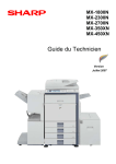
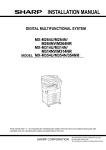
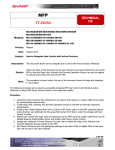
INSTALLATION MANUAL
DIGITAL MULTIFUNCTIONAL SYSTEM
MODEL
MX-M623N
MX-M623U
MX-M753N
MX-M753U
Parts marked with " " are important for maintaining the safety of the set. Be sure to replace these parts with
specified ones for maintaining the safety and performance of the set.
SHARP CORPORATION
This document has been published to be used
for after sales service only.
The contents are subject to change without notice.
MX-M753N
[1] MX-M623N/M623U/M753N/
M753U
1.
Installing (use) conditions
(3)
Power frequency, waveform
5GTXKEG/CPWCN
The frequency must be within the range of the specified frequency
r2%. If power waveform is deformed, a trouble may occur.
(4)
Safety
Be sure to properly ground the machine.
Before installing the machine, check that the following installing
(use) conditions are satisfied.
Grounding (earth connection) must be performed before inserting
the power plug into the power outlet.
If the installing (use) conditions are not satisfied, the machine may
not display full performances, resulting in troubles. It may also
cause safety problems. Therefore, be sure to arrange the installing
(use) conditions before setting up the machine.
When disconnecting the earth connection, be sure to disconnect
the power plug from the power outlet in advance.
No.
1
2
3
4
5
Content
Bringing space
Installing space
Power source (Capacity, fluctuation, safety)
Floor strength
Direct rays of the sun, dust, temperature, humidity, gases,
chemicals
A. Bringing space
For installation of a large size machine, be sure to check that the
door size is wide enough before bringing in.
(5)
Power plug
Check the shape of the power plug of the machine, and insert it into
a power outlet of the acceptable shape.
D. Floor strength and level
This machine is considerably heavy and becomes heavier with an
option installed.
The floor must be strong enough for assuring safety.
If the unit is not horizontally installed, the toner density control is not
performed normally, degrading the copy quality.
If not, color shift or image distortion may occur.
B. Installing space
The following space must be provided around the machine in order
to assure machine performances and proper operations.
If any option is installed, provide the additional space for installing
it.
Adequate space must be provide behind the machine for proper
ventilation heat and dust. If not, the machine cannot exhibit functions against heat and dust, causing some troubles.
11-13/16"
(30cm)
11-13/16"
(30cm)
17-23/32"
(45cm)
C. Power source (Capacity, voltage, frequency,
safety, plug)
E. Direct rays of the sun, dust, temperature,
humidity, gasses, chemicals, vibration
(1)
Temperature and humidity
This machine is designed to perform properly under the specified
temperature and humidity. If the temperature and humidity exceeds
the specified range, the machine may not operate properly and or
cause equipment failure.
Especially when the humidity is too high, paper absorbs humidity to
cause a paper jam or dirty copy.
Do not install the machine near a heater, a cooler, or a humidifier.
If the power specifications are not satisfied, the machine cannot
exhibit full performances and may cause safety trouble.
Strictly observe the following specifications.
(1)
Power capacity
Check that the following power capacity is satisfied. If not, additionally provide a power source.
Current capacity
Japan: 20A or more
Dew may be formed inside the machine to cause a trouble. Use
enough care for ventilation.
100V: 15A or more
200V: 10A or more
NOTE: Check the shape of the power plug of the machine, and
insert it into a power outlet of the acceptable shape.
(2)
Humidity㧔RH㧕
85%
60%
Power voltage
Measure the voltage during copying to check that the voltage is in
the range of the specified voltage r10%.
If the voltage is outside the specified range, use thicker lead wires
to reduce impedance.
20%
(An electrical work is required.)
Use of a step-up transformer is also available. In this case, the
capacity must be great enough for the max. power consumption of
the machine.
• Working environment
Temperature: 10 to 35qC
Humidity: 20 to 85% RH
Atmospheric pressure: 590 to 1013hPa (altitude: 0 to 2000 m)
MX-M753N MX-M623N/M623U/M753N/M753U 1 – 1
(2)
Dust
F. Note for handling PWB and electronic parts
If dust enters the machine, it may cause dirty copy and a paper
jam, resulting in a shortened lifetime.
(3)
When handling the PWB and the electronic parts, be sure to
observe the following precautions in order to prevent against damage by static electricity.
1)
When in transit or storing, put the parts in an anti-static bag or
an anti-static case and do not touch them with bare hands.
2)
When and after removing the parts from an anti-static bag
(case), use an earth band as shown below:
Direct rays of the sun
If the machine is installed under the rays of the sun, the exterior of
the machine may be discolored and abnormal copies may be produced.
• Put an earth band to your arm, and connect it to the
machine.
(4)
Gases and chemicals
Do not install the machine at a place where there are gases and
chemicals. Especially be careful to avoid installation near a diazotype copier, which produces ammonium gas.
Copy quality may be adversely affected and a trouble may be
caused.
• When repairing or replacing an electronic part, perform the
procedure on an anti-static mat.
(5)
Vibration
Avoid installation near a machine which produces vibrations.
If vibrations are applied to the copier machine, copy images may be
deflected and a trouble may be caused.
MX-M753N MX-M623N/M623U/M753N/M753U 1 – 2
G. Note for handling the drum unit, the transfer
unit, the developing unit, and the fusing unit
3.
Unpacking
A. Unpacking procedure
When handling the OPC drum unit, the transfer unit, and the developing unit, strictly observe the following items.
1)
Remove the PP band.
If these items are neglected, a trouble may be generated in the
copy and print image quality.
2)
Remove the top case.
3)
Remove the top pads.
4)
Remove the adjuster cover and the screw (in the bag) from the
top pad L.
5)
Lift the machine slightly, and remove the bottom pad L.
6)
Lift the machine slightly, and remove the bottom pad R.
(Drum unit)
1)
Avoid working at a place with strong lights.
2)
Do not expose the OPC drum to lights including interior lights
for a long time.
3)
When the OPC drum is removed from the machine, cover it
with light blocking material. (When using paper, use about 10
sheets of paper to cover it.)
4)
Be careful not to attach fingerprints, oil, grease, or other foreign material on the OPC drum surface.
(Transfer unit)
1)
Be careful not to attach fingerprints, oil, grease, or other foreign material on the transfer roller.
(Developing unit)
1)
Be careful not to attach fingerprints, oil, grease, or other foreign material on the developing unit.
(Fusing unit)
1)
Be careful not to put fingerprints, oil, grease, or other foreign
material on the fusing roller and the external heating belt.
2)
Do not leave the fusing roller in contact state for a long time.
2.
No.
1
2
Transit and delivery
Content
Implements, facility,
and man power
Delivery
Method
Use a forklift. (If no forklift is available,
manpower of two persons is required.)
Transit must be made in packed condition.
A. Implements, facility, and manpower
It is recommended to use a forklift for bringing in the machine for
safety.
If no forklift is available, man-power of two persons is required. The
machine is considerably heavy, and requires safety precautions for
delivery and installation.
Transit of the machine must be made in packed condition to the
installing place.
Since the hard disk drive is built in the machine, use care not to
exert vibrations or shocks to the machine when in transit.
B. Delivery
Remove the packing materials prior to installation in the office environment.
MX-M753N MX-M623N/M623U/M753N/M753U 1 – 3
7)
B. Removal of the fixing tape, protection material
and parts packed together
Remove the slope.
* Slope: Parts
Part name
Skid slope
8)
Part code
DKiT-0367FCZZ
Attach the slope to the concave section of the skid.
C. Check the parts packed together
1)
9)
Check that all the parts are in the package.
Hold the machine grips and push them down in the arrow
direction.
NOTE: This machine includes a hard disk drive, which must be
protected against vibrations and shocks.
Never move the machine with the power ON.
1
2
3
4
5
6
1
2
3
4
5
6
Adjuster cover
Adjuster cover fixing screw
Operation manual storage cover
Driver (CD-ROM)
Operation manual
Delivery and installation report
NOTE: When the machine is moved over a bump, hold the grip on
the right side of the machine to lift and cross the bump
over. This is because the casters may be broken for a big
bump.
MX-M753N MX-M623N/M623U/M753N/M753U 1 – 4
x1
x3
x1
x1
x1
x1
4.
Installation
B. Lock release
A. Adjuster cover installation
1)
1
2
Move the main unit to the installing position, and turn the
adjuster to fix the main unit.
(1)
Lock position
No. 2/3 mirror base lock screw
Tray rotation plate fixing material
No. 2/3 mirror base lock release
Remove the No. 2/3 mirror base fixing screw and the label of note
for unpacking on the left side.
2)
Remove the bottom tray from the main unit.
3)
Install the adjuster cover to the main unit.
(2)
Tray rotation release plate lock release
Remove the paper feed tray rotation plate fixing screw and the
label of note for tray.
[Tray 1, Tray 2]
4)
Insert the bottom tray into the main unit.
[Tray 3, Tray 4]
MX-M753N MX-M623N/M623U/M753N/M753U 1 – 5
C. Press the fusing section (upper and lower heat
rollers) and remove the process separation
pawl fixing block.
D. Set developer
1)
Pull the knob on the left door to pull out the left door.
(1)
Supply developer
1)
Open the front cabinet.
2)
Loosen the blue screw of the process cover, and tilt down the
process cover toward you.
1
2
2
1
2)
3)
Loosen the blue screw which is fixing the developing unit.
4)
While pressing the developing unit lock lever, pull out the
developing unit.
Turn the pressing screw in the fusing section as shown in the
figure below (fully loosen them) to press the heat rollers
together.
Hold the strap of the developing unit and remove the developing unit.
3)
Remove the separation pawl fixing block from the process unit.
5)
4)
Remove the screws and remove the DV cover.
Replace the left door.
MX-M753N MX-M623N/M623U/M753N/M753U 1 – 6
6)
While supplying developer to the developer supply port of the
developing unit, turn the MG gear clockwise with a plus screwdriver to supply all developer to the developing unit.
3)
Insert the toner cartridge until it is locked.
NOTE: When supplying developer, do not touch the MG roller with
bare hands.
(3)
Set the toner density reference control level
Insert the power plug into the power outlet. With the front cabinet
open, turn on the power switch of the main unit.
1)
7)
Install the DV cover to the developing unit.
8)
Insert the developing unit to the main unit and fix it with the
blue screw.
9)
Close the process cover and fix it with the blue screw.
(2)
1)
Toner set
Enter the SIM 25-2 mode.
2)
Close the front cabinet.
3)
Press [EXECUTE] key to execute the simulation. Toner is
stirred for 3 minutes. The average level of the sensor detection
level is set (stored) as the reference toner density control
value.
Remove the toner cartridge from the box, and shake it several
times horizontally.
E. Paper size change
(1)
Tray 3 or tray 4 paper size change
1)
Pull out the tray 3 or the tray 4.
2)
Hold and slide the fixing knob (slide system) of the partition
plates A and B to fit with the size of paper to be supplied.
NOTE: Be sure to shake the toner cartridge horizontally.
NOTE: Be careful not rotate as shown in the figure below.
2)
Insert the toner cartridge into the main unit insertion port as
shown below. In this case, do not turn the cartridge.
3)
Supply paper into the tray.
4)
Push the tray.
NOTE: Note that a certain special paper cannot be used for tray 4.
To use special paper, use tray 3.
(2)
Tab paper setting
To use tab paper, install the exclusive-use guide tray 3.
Note that tray 4 cannot be used.
1)
Remove the exclusive-use guide from the storage position left
inside of the machine.
MX-M753N MX-M623N/M623U/M753N/M753U 1 – 7
4)
2)
Pull out tray 3.
3)
Slide the partition plate to tab paper as shown in the figure
below and install it so that it covers the partition plate.
Touch the [Change] key in “Tray 1”.
Back
Tray Settings
Tray 1
Type
Plain
Size
8-1/2x14
Change
Paper Property
Fixed Paper Side
Disable Duplex
Disable Staple
Disable Punch
Feeding Approved Job
Copy
Print
Fax
I-Fax
Doc. Filing
5)
Select [Recycled] from the “Type” select box.
6)
Make sure that [Auto-Inch] is selected in the “Size” select box.
7)
Touch the [OK] key.
The above steps change the paper settings for tray 1 to 8-1/2”
x 11” recycled paper.
System Settings
Cancel
Tray Settings
Tray:
Type:
Size:
OK
Tray 1
Recycled
8-1/2x11
216x330(8 1/2x13)
A3,A4,A4R,B4,B5,B5R,
Paper Property:
Print
Copy
I-Fax
Fax
F. Other parts setting
(1)
1)
4)
Supply tab paper with the print face up into tray 3.
5)
Push in tray 3.
(3)
Operation manual storage cover installation
Install the operation manual storage cover to the rear cabinet.
Changing the tray settings
When you change the paper in a tray, the tray settings in the system settings must also be changed.
1)
Press the [SYSTEM SETTINGS] key.
SYSTEM
SETTINGS
2)
(2)
Other notes
Check to insure that the cable connected to the service terminal (A
in the figure below) is 3m or less.
Configure the tray settings in the touch panel.
Touch the [Paper Tray Settings] key.
Admin Password
System Settings
Exit
List Print
(User)
Total Count
Default Settings
Paper
p
Tray
Settings
Address Control
Fax Data
Receive/Forward
Printer Condition
Settings
Document Filing
Control
USB-Device Check
(A)
3)
Touch the [Tray Settings] key.
System Settings
Paper Tray Settings
Back
Tray Settings
Paper Type Registration
Auto Tray Switching
Custom Size Registration (Bypass)
MX-M753N MX-M623N/M623U/M753N/M753U 1 – 8
G. Cleaning
[Check with the gray test chart (UKOG-0162FCZZ)]
(1)
In the copy density check with the gray test chart, check to insure
the following conditions.
1)
Main charger
Reciprocate the MC cleaner shaft back and forth to clean the
electrode tip.
Patch 2 is
slightly copied.
1
2
SHARP gray chart
SHARP GRAY CHART
3
4
5
6
7
8
9
10
W
Patch 3 is copied.
Patch 1 is not copied.
[Check with the servicing color test chart (UKOG-0317FCZZ/
UKOG-0317FC11 or UKOG-0326FCZZ/UKOG-0326FC11)]
Check to confirm that it is in the conditions shown below.
Serviceman chart (Color patch section)
H. Specifications setup
Used to set the specifications with SIM26 according to the customer's request.
SIM No
26
6
Content
Used to set the destination.
To customize the following items after completion of the destination
setup, change the set values.
SIM No
26
2
3
5
18
52
53
65
Content
LCC paper size setting
Used to set the auditor specification mode.
Used to set the count mode of the total counter and the
maintenance counter.
Used to set YES/NO of the toner save mode
(Only in UK and Japan versions)
* For other destination versions, this setup is made by
the user program.
Used to set YES/NO of counting when non-print paper
is passed through each counter.
Used to set YES/NO of user calibration permission.
Used to set the limit number of sheets for stapling.
Patch 7 is slightly
copied or not copied.
(2)
Printer density and gradation check
If no printer option is installed to the U model, the following procedures are not required. (SIM64-5 does not operate.)
NOTE: Before checking the printer density and gradation, be sure
to execute the following jobs.
* Execute the high density image correction (Process correction)
forcibly. (SIM 44-6)
* Execute the half-tone image correction forcibly. (SIM 44-26)
(Method 1)
Execute SIM 64-5 to print the print test pattern.
Set each set value to the default and press [EXECUTE] key. The
print test pattern is printed.
I. Image quality check
(1)
Copy density and gradation check
NOTE: Before checking the copy density and gradation, be sure to
execute the following jobs.
* Execute the high density image correction (Process correction)
forcibly. (SIM 44-6)
* Execute the half-tone image correction forcibly. (SIM 44-26)
(Method)
Make a copy of the gray test chart (UKOG-0162FCZZ), and check
that it is proper.
Note for checking the copy mode density
To check the density, use the gray test chart (UKOG-0162FCZZ).
Set the copy density level to “Manual 3” in the Text/Printed Photo
mode (Manual).
The print density must be changed gradually from the lighter level
to the darker level. The density changing direction must not be
reversed.
In addition, all the picture quality adjustment settings in the user
adjustment mode must be set to the default (center).
MX-M753N MX-M623N/M623U/M753N/M753U 1 – 9
(Method 2)
Execute SIM 67-25 to print the adjustment check pattern.
L. Necessary procedures before moving the
machine
1)
The patch density is identical between patches or not reversed.
The patch density is changed gradually.
If the following options are installed, remove all of them from
the machine.
• Finisher
PRINTER CALIBRATION
• Large capacity tray
Patch A or B is slightly copied.
2)
Remove the following consumable parts from the machine.
• Paper
A B C D E F G H I J K L MN O P
• Toner cartridges
Q (Max)
Low density
• Development cartridge
High density
3)
Lock the following sections.
• Scanner (Optical section)
• Paper cassette lift plate
4)
Remove the adjuster cover, and lift the adjuster.
The print density must be changed gradually from the lighter level
to the darker level. The density changing direction must not be
reversed.
NOTE: Since the hard disk drive is built in the machine, use care
not to exert vibrations or shocks to the machine when in
transit.
Patch A or B is slightly copied.
M. USB PORT selection
J. Function and operation check
There are two USB ports; one on the front frame side and the other
on the rear frame side. Only one of them can be used at a time. Do
not connect the two USB ports simultaneously.
Check that the following operations are normal.
Check item list
Key-in (operation panel)
Display (operation panel)
Paper feed
Hand feed
operation
Main unit paper
tray
Desk unit paper
feed tray
Paper size detection
Originals size
Original table
detection
mode
DSPF mode
RSPF mode
DSPF/RSPF
S-S mode
operation / two
D-S mode
sided copy
S-D mode
D-D mode
Bookbinding operation
Stapling operation
Grouping operation
Sorting operation
Paper exit operation
Equipped condition
When shipping, the port on the front frame side is valid and the port
on the rear frame side is invalid. When using the USB port, be careful of the total current consumption not to exceed 500mA.
The valid port can be switched by changing the setting of the MFP
PWB DIP SW.
With the desk unit installed
Select the valid USB port according to the user’s request.
* The default setting for SW1/SW2 is OFF.
MFP PWB DIP SW
SW 1
SW 2
OFF
OFF
OFF
ON
USB I/F
Port on the front
Port on the rear
frame side
frame side
Valid
Invalid
Invalid
Valid
When the finisher is installed
When the finisher is installed
When the finisher is installed
When the finisher is installed
When the exit tray unit (MX-TRX2)
is installed
Upper side: DIP-SW1
Lower side: DIP-SW2
When tilted toward you: OFF
When tilted to the PWB side: ON
K. Setup and adjustment data recording
Print the various setup data and the adjustment data (list) with
SIM22-6 and keep the data.
• In case of a memory trouble, if the data are not kept, all the
adjustments must be made again.
• If the data are kept, the setup values and the adjustment values
can be entered without adjustments, shortening the servicing
time.
NOTE: After completion of option installation, revise all the firmware to the latest version.
MX-M753N MX-M623N/M623U/M753N/M753U 1 – 10