1
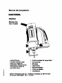
Owner's Manual
CRRFTSMANe
CUTTER
Model No.
183.172500
•
•
•
•
•
•
•
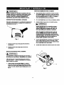
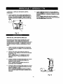
CAUTION:
Before using this Cutter,
read this manual and
follow all its Safety Rules
and Operating
Instructions.
SafIty Instructions
Accessories
Assembly
Operation
Maintenance
Parts List
Espenol
Sears, Roebuck and Co., Hoffman Estates, IL 60179 USA
ParL No. 149277480001
Rev. 1
07/13/01
SECTION
PAGE
warranty ........................................
2
Product Specifications .......................
2
Power Tool Safety ............................
3
Cutter Safety ..................................
4
Elech'ical
Requirements & Safety ........5
Accessories ....................................
5
SECTION
PAGE
Carton Contents ..............................
Know Your Cutl_. .............................
6, 7
8
Assembly & OpemUon ......................
Maintenance ...................................
9 - 17
17
Repair Parts ...................................
Parts & Service Availability ................
18 - 22
23
llllJ
FULL ONE YEAR WARRANW
If this Cutter fails due to a defect in material or workmanship within one year of date of
purchase, Sears will at its optionrepair or replace it free of charge.
Returnthis Cutter to a Sears Service Center for repair,or to place of purchase for replacement.
This warranty
gives
from state to state.
you
Seam,
l&
WARNING
specific
Roebuck
legal
and
fights,
and
you may
also have
other
Co., Dept. 817 WA, Hoffman Estates,
rights
which
may vary
IL 60179
I
Some dust created by power sanding, sawing, grinding, drilling and other coaMructlon
activities
chemlcaia known (to the State of California) to cause cancer, birth defects or olther reproductive
exampfes of these chemicals
are:
•
Lead from iaad-based
paints
contains
harm. Some
•
Crystalline silica Wont bricks, cement and other masonry products
•
Arsenic and chrominm
from chem..ally
treated lumber
Your risk from these exposure
varies, depending
on how often you do this type of work. To reduce your
expo6ure to these chemicals,
work In a well ventliated
area and wod( _
approvad safety equipment
such as
those dust masks that ere specially designed to filter out microscopic
parl_.
l;,l [o] lU[oM
Motor Rating ......................
Amperes ...........................
Speed (no load) ..................
120V, 60Hz, AC
4.0 Amperes
30000 RPM
Motor Horsepower ......
Weight .....................
tl3 HP (Ma_mum
3.75 kg
Developed)
I,_, WARNINGI
To avoid electrical
hazards,
This cutter is wired atthe
time delay fuse or curcuit
damaged in any way.
fire hazards
or damage
to the cutter,
use proper
circuit protection.
factory for110-120
Volt operation.
It must be connecl_d
to a 110-120 Voit115 Ampere
breaker.
To avoid shock or fire, replace power cord immediately
If It is worn, cut or
Before using your cutter, It is crltinal that you read and undemtand
miss could result in serious injury to you or damage to the cutter.
these mlGety rules.
Failure
to follow
these
[A WARNINGJ
Before using your cutter, it is critical that you read and understand
to follow these rules could result in serious injury to you or damage
Good safe_ practices are a combina_n
of common
sense, staying alert and undemtanding howto use your
power tool. To avoid mistakes that could cause sedous
mJury, do not plug in your cutter until you have read and
understood the following safety rules:
1.
READ and become familiar with this entire Owner's
Manual. LEARN the tool's applications, limitations and
possible hazards.
Look for this symbol that identif'ms
precautions. It means CAUTIONI
YOUR SAFETY IS INVOLVEDI
IN PLACE
Failure
15, REMOVE
ADJ_
KEYS AND WRENCHES.
Form the habit of checking to see that keys and
adjusting wrenches are removed from the tool before
turning "ON'.
16. NEVER LEAVE TOOL RUNNING
UNATTENDED.
TURN THE POWER "OFF".
Do not leave the tool
before it comes to a complete
stop.
17. NEVER STAND ON TOOL. Serious injury could
occur if the tool is tipped or if the cutting tool is
unintentionally contacted.
2. IA WARNINGJ
GUARDS
these safety rules.
to the cutter.
important safety
BECOME ALERTt
3.
KEEP
4.
DO NOT USE IN A DANGEROUS
ENVIRONMENT
such as damp orwet locations or exposure to rain.
Keep work area well lighted.
and in working order.
18. DO NOT OVERREACH.
balance at all times.
19. MAINTAIN TOOt_
WITH CARE. Keep tools sharp
and clean for molt efficient and safest performance.
Follow instruc_ofls for lubricating and changing
accessories.
20.
5. DO NOT use power tools in the presence of
flammable liquidsor gases.
6.
KEEP WORK AREA CLEAN.
workbenches invite accidents.
Cluttered
7.
KEEP CHILDREN AWAY. All visitors should be kept
at a safe distance from the work area.
8.
DO NOT FORCE THE TOOL
ItwHIdothejobbetter
and safer at the rate for which if was designed.
9.
USE THE RIGHT TOOL.
Do not force the tool or
attachment to do a job for which it is not designed.
Keep proper footing and
areas and
CHECK FOR D_Mt, GED PARTS.
Before further use
of the tool, a guaed or other part that is damaged
should be carefuNy checked to ensure it will operate
properly and perfoml its intended function. Check for
alignment of moving parts, binding of moving parts,
mounting and any _her conditions that may affect its
safe operation. Aguard or other part that is damaged
should be properly repaired or replaced.
21. MAKE WORKI_IOIP
CHLD PROOF with padlocks,
master switches or by removing starter keys.
22. DO NOT operate the tool if you are under the
influence of any drugs, alcohol or medication that
could impair your abHify to use the tool safely.
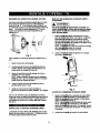
10. WEAR PROPER APPAREL.
DO NOT wear loose
clothing, gloves, neckties, rings, bracelets or other
jewelry that may get caught in moving pans. Non-slip
footwear is recommended.
Wear protective hair
covering to contain long hair.
23. USE DUST COLLECTION
SYSTEM wherever
ossible. Dust generstod from certain materials can
e hazardous to your health and in some cases, a fire
hazard. Always operate the power tool in a well
ventilated area with adequate dust removal.
11. WEAR A FACE MASK OR DUST MASK. Sawing,
cutting, drilling and sanding operations produce
hazardous dust.
24.
12. DIe, CONNECT TOOLS FROM THE POWER
SOURCE before servicing and when changing
accessories such as blades, bits, cutters, etc.
13. REDUCE THE RISK OF UNINTENTIONAL
STARTING.
Make sure the switch is in the "OFF"
position before plugging into the power source.
14. USE ONLY RECOMMENDED
ACCESSORIES.
Consult the Owner's Manual for recommended
accessories. The use of improper accessories
cause injury to you or damage to the tool.
ALWAYS
WEAR EYE PROTECTION.
Any power
tool can throw foreign objects
into your eyes which could
cause permanent eye damage.
ALWAYS wear safety goggles
(not glasses) that comply with
ANSI safety stenderd Z87.1. Everyday glasses have
only impact reststont lenses. They ARE NOT safety
glasses. Safety goggles are available at Sears.
I& WARNll_I
may
Glasses or gollIlII
Ztt7.1 could cI
not In compliance
with ANSI
I_dous
injury when they break.
SAVE THESE INSTRUCTIONS FOR REFERENCE
_ARNING_
For your safety, do not plug in your cutter or try to
use any accessory
until it is complemly
assembled
and installed according to these Instructions,
and
until you have read and understood
this Owner's
Manual.
11. NEVER
Failure
13. NEVER START THE TOOL WHEN THE BIT IS
TOUCHING
THE WORKPECE.
The bit may catch
serious
to follow these
safety
rules will result
in risk of
injury.
HOLD THE
WEAR EYE PROTECTION.
This high speed tool will
throw particles from the workpiece during operation.
Make sure safety glasses have side shields.
IN ONE HAND
12. NEVER PLACE HANDS IN THE PATH OF THE
CUTTER AND UNDER THE WORKPIECE.
the workpiece
1.
WORKPIECE
while operating the fool with the other hand.
14. ALWAYS
DURING
causing loss of control.
HOLD THE TOOL WITH TWO
START-UP
AND OPERATION.
HANDS
When
starting, motor torque will cause the tool to twisL
2.
3.
4.
USE FACE OR DUST MASK along with safety
goggles if cutting or routing operation is dusty. Make
sure work area is well ventilated.
USE HEARING PROTECTION,
extended periods of operation.
NEVER
USE DULL
particularly
during
16. ALWAYS HOLDTHE
TOOL BY THE INSULATED
GRIPPING
_UlIRFACES ON THE BODY OF THE
OR DAMAGED
BITS.
Damaged
bits can break without warning. Dull bits may ovedoad
the motor, cut slowly and are difficult to control. They
will also overheat and possibly break.
ALWAYS MAKE SURE THE WORKPIECE
IS FREE
OF NAILS AND OTHER FOREIGN OBJECTS.
If the
bit strikes a nail it will jump sideways and possibly
break.
6.
DO NOT USE THIS TOOL FOR DRILLING
It is NOT intended to be used as a ddll.
ALLOW
CLEARANCE
UNDER
HOLES.
WORKPIECE
for bit
to b'avel. Never place workpiece on hard surfaces
such as concrete etc. The bit may jump or break
when contacting a surface other than the one being
cut.
ALWAYS
SET THE
DEPTH
GUIDE TO THE
APPROPRIATE
DEPTH.
Use tool with the depth
guide flat against the work surface for better control of
the tool.
9.
NEVER
PLATE,
USE THE TOOL wrrHOUT
THE SOLE
PRECISION
HANDLE OR ROUTER BASE
attached and appropriately
10. ALWAYS
STEADY
15. TURN OFF ALL CIRCUIT BREAKERS
AND
REMOVE ALL FUSES in the work area when cutting
into walls or blind areas.
adjusted.
TOOL where fllere is any possibility of the cutter
contacting hidden elecb'ical wires or the cord of the
tool. Contectwith "live" wires will make exposed
metal parts of the tool _live" causing an electrical
shock to the operator.
17. WHEN CUTTING DRYWALL
ELECTRICAL
OUTLET
OPENINGS
using the outlet as a guide, always cut in
a counter c_
direction. The natural tendency
of the tool to pull to the left will cause a "hugging"
action toward the outlet box, resulting in a heater cut.
18. NEVER LAY THE TOOL DOWN UNTIL THE
CUTTER COB
TO A COMPLETE
STOP. A
spinning bit (:an come in contact
pull it out of yqmr con_ol.
19. NEVER
TOU_H
THE
with the surface and
BIT IMMEDIATELY
AFTER
USE. The bit!will be too hot to be handled with bare
hands and _dll bum your fingers.
20. ALWAYS RI_TI_HTEN
COLLET AND ALL
ADJUSTMIENT8
before starting the tool after a bit or
accessory h_ been changed.
Loose bits and
adjuskneolB_
cause unexpected shifting of the tool,
resulting in I_
bf control and injury from the bit or
cutter being thmt_.
CLAMP WORKPIECE
TO HOLD IT
WHEN CUTTING.
This will free both hands
for operating the tool.
SAVE THESE INSTRUCTIONS FOR REFERENCE
[ellJll]illl_lile]:l
[lJli=|ilPl_k_._--"'Jllll].
This cutter is double insulated
electrical shock.
to protect you from
IA WARNING I
Double
insulated
tools
am equipped
with a polarized
plug (one blade is wider than the other). This plug will
f_ into a polarized outlet only one way. If the plug
does not fit fully into the outlet, reverse the plug. If it
still does not fit, contact a qualified etacITIclan to
install a polarized
outlet. Do not alter the plug in any
way. Double insulation eliminates the need for the three
wire grounded
system.
power cord and grounded
power supply
Avoid body contact wlth grounded surfaces such as
pipes, radiators, ranges and refrlgerators.
There is an
increased risk of electric shock if your body is grounded.
Do not expose power tools to rain or wet conditions.
Water entering a power tool will increase the risk of
electric shock.
Do not abuse the cord. Never use the cord to carry
the tool or pull the plug from the outteL Keep cord
away from heat, oil, sharp edges and moving parts.
Replace damaged cords immediately.
increase the risk of electhc shook.
Damaged
cords
Be sure your extension
I
Always make sure the receptacle Is polarized.
are not sure, have a qualified electllclsn
check
receptacle.
wired and in
Use a separate electrical circuit for your power tools.
This circuit must not be less than 14 gauge wire and
should be protected with either a 15 Ampere time delay
fuse or circuit breaker. Before connecting the power tool
to the power source, make sure the switch is in the OFF
position and the power source is the same as indicated on
the nameplate.
Running at lower voltage will damage the
motor.
IA WARNINOI
damaged
or worn
extension
cords
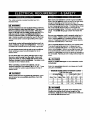
Select the appropriate extension cord gauge and length
using the chart below.
Ampere
If you
the
conS is properly
good condition, Always replace a damaged extension
cord or have it repaked by a qualified electrician before
using it. Proteet your extension cord from sharp objects,
excessive heat and damp or wet areas.
MINIMUM
WARNING
[ata];llk
Make sure your extension
cord is in good condWon.
When using an extension cord, be sure to use one heavy
enough to carry the current the tool will draw. An
undersized cord will cause a drop in line voltage resulting
in loss of power told overheating.
The table below shows
the correct size to use according to cord length and
nameplate ampere rating. If in doubt, use the next heavier
gauge. The smager the gauge number the heavier the
cord.
Repair or rspla¢l)
immediately.
When operaUng a power tool outdoors, use an
outdoor exteesfon
cord marked "W-A" or"W".
These
cords are rated for outdoor use and reduce the risk of
electric shock.
IA,
1:l)[41l:ll_k'l[I]_:
More Than
0
GAUGE (AWG) EXTENSION
(120 Volt use only)
Rating
Not
More Than
6
25'
18
50'
16
10
12
16
18
16
14
16
16
12
0
12
CORDS
Total length in feet
100'
16
150'
14
14
12
14
12
NOtApplicable
_A WARNINGI
Keep the extm_
cord clear of the working area.
Position the coRl so It will not get caught on the
workptace,
too_ or any other obstructions
while you
are working
w#h the power tool.
_Xo(o] II.$'_o]
I
=]i;i_'
r II _J_mn1_i_
!i !
AVAILABLE
[A
ACCESSORIES
WARNING
UNPACKING
Visit your Sears Hardware
Department
or see the Seam
Power and Hand Tool Catalog for an assorbllent of
recommended
•
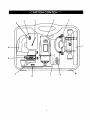
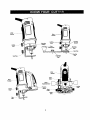
CONTENTS
Carefully unpackthe
cutter and all its parts. Compare
against the =Cutm" Components"
chart below.
NOTE: See Page 7 for illustm'don of parts.
for use with this spiral saw:
_/e" Spiral Cutter Bits
1/8" Hobby Rotary Tool Accessories
;,
Cutters
_, Polishers
Sanders
;,
Grinders
Most ¼" Shank Router Bits
WARNING
CUTTER
KEY
_C B
--
IA wAe.,.o]
Use only accessories
designed for this spiral cutter
avoid severe Injury or tool damage.
to
D
G
Do not use any accessory
unless
read the Instructions
or Owner's
I
To avoid fire or, toxic reaction, never use gasolin e,
naphtha, acetolm_ lacquer thinner
or similar highly
volatile solvents to clean the cutter.
A
accessory.
CARTON
If any part is mlsek!tg or damaged,
do not plug the
cutter into the PoWer source until the missing or
damaged part Is replaced and assembly
is complete.
IA,
•
•
CHECKING
IA WARNmGI
I
Use only accessories
recommended
for this spiral
cutter. Follow instructions
that accompany
accessories.
Use of improper accessories
may cause
Injury to the operator or damage to the spiral cutter.
accessories
_
you have completely
Manual for that
J
K
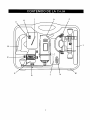
COMPONENTS
DESCRIPTION
QTY
CuWn_ Tool
1
Precil_k:)n Handlewith Sole Plata
Freehand Sole Plate Attachment
1
1
Circle Cutter Attachment
1
R0U _t_TBase Attachment
1
118" Col_t Sleeve
1/4" Co41_t Sleeve
Lateral Style Drywall Cutter
Collet Wrench
t
1
1
I
Coll_Wrench
Holder
Owr_, _! Manual
Canyll_ Case
1
1
1
c_€_
Instaita=n
Adepter
1
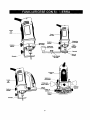
[_
C
[o,Io_
K41_e]vAvJ
k_e]l_
[e,]l]lil_l
Mou_ting
L
Loddng
Knob
/
MBr°Ua_
Circle
CutBng Knob
Mir_g
Sole Plate
Y'_
Sole Plate
Motor ....
Housing
_F_
J
Pi_
_
_'-_'"_
Mounting
Disc
_
Adjusting Knobs
Locking
KnOb
P_dsior_
Handle
eev_
KnObs
|
Sole
Plate
_/
Router
Base
IA
WARNINGI
Remove the plug from the power
assembly,
changing accessorkm
making adjustments.
This safety
prevent accidental
etarting of the
result In eertous Injury.
ON I OFF
source before
or cutters and
action wftl help
tool which could
INSTALLING
4.
CUTTING
BITS
Insert new bit (4) into the colleL
I_
WARNING
I
Insert the bit all the way Into
pull it back between 111s"and
airspace
between the motor
help prevent overheating
the
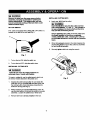
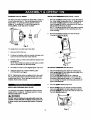
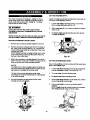
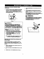
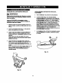
SWITCH
This cutter is equipped with a sliding ON / OFF switch (1)
located on the side of the tool (see Fig. 1 ).
the collet and then
tla". This creates an
shaft and the bltto
bit.
Before tight=ruing the collet on the bit, make sure
the flutes (poItion)
of the bit are completely
visible outside the colleL Clamping the collet on
the bit flutsl w#l result in broken bits and possible
injury.
5.
When bit is propedy placed in the collet, depress the
shaft locking button and turn the collet nut clockwise
by hand as far as possible.
6.
Securely
tighten collet nut using the wrench.
Fig. 1
1.
To turn the tool ON, slide the switch up.
2.
To turn the tool OFF, slide the switch down.
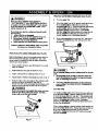
INSTALLING
IA
CUTTING
BITS
WARNING]
cutter bit and router bit cutting surfaces
extremely sharp.
Handle with caution.
am
To insert a cutting bit, use the collet wrench which is in
the wrench holder attached to the power cord.
Depress the shaft
collet lock nut (2)
the locking button
shaft from turning
locking button (1) and rotate the
clockwise with the other hand until
drops into place, preventing the
(see Fig. 2).
2.
While continuing to hold the shaft locking button IN,
use the collet wrench (3) to turn the collet nut counter
clockwise. Loosen the collet nut 2 or three turns.
3.
Remove
bit if one is already installed in the tool.
Fig. 2
CHANGING
COLLET
INSERT
INSTALLING
The bits for this tool are locked into place with a collet nut
FREEHAND
SOLE
PLATE - cont'd
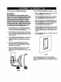
Remove a_
locking knob (1) from the base of
the cutter motor housing (see Fig. 4). Slide freehand
sole plate mounting bracket (2) onto the bottom of
motor housing (3) until the mounl_ng hole (4) lines up
with the hole in the motor housing.
NOTE: The tab on the side of the sole plate mounting
band must be inserted into the matching slot in the
motor housing.
(1) and collet lsee Fig. 3). The tool is assembled at the
factory with a "/8"collet (2) which is used to hold the
cutting bit. An addil_onal ¼" collet (3) is supplied for
holding SMALL router bits with a I/4" shank.
2. Re-insert accessory locking knob intothe motor
housing and securely tighten.
Fig.
3
To change from one collet size to the other:
1.
Remove
bit from the tool.
2.
Continue turning the collet nut counter clockwise
it can be removed from the motor shaft (4).
3.
Pull the collet out of the motor shaft and replace it with
the other one.
until
NOTE: Each collet is the same on both ends, so either
end can be inserted into the motor shaft.
4.
Re-install the collet nut and slighity tighten it by hand.
5.
Install the new bit as outlined in INSTALLING
CUTTING
BITS on Page
Fig. 4
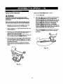
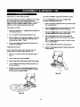
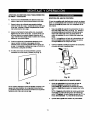
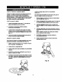
ADJUSTING FREEItAND SOLE PLATE
Adjust freehand sole plate depth by loosening the
depth gauge knob (5) and sliding the sole plate (6) in
or out as required (see Fig. 5).
NOTE: Bet the depth gauge so the cutting bit
protrudes beyond the sole plate '/8" more than the
thickness of the material being cut. For example, if
you are cutting 5/8" drywall, the bif should protrude ¾"
beyond the sole plate.
9.
NOTE: Tightening the collet nut without a bit in the collet
will cause the collet hole to become smaller and make
installing bits difficult. When storing the tool with no bit
installed, leave collet nut loose.
l:|=Izl==f±_l_li_
INSTALLING
FREEHAND
fo]II=l
2.
I'nI_II
SOLE PLATE
tighfan depth gauge
knob.
Before starting to cut you should re-check bit depth,
make sure sole plate is at right angles to the bit and
securely t_ned.
Re-check the collet to make sure
the bit is sec_
fastened.
The freehand sole plate is designed for basic freehand
cutting with the cutting bit. It is ideally suited for cutting
electrical outlet holes in drywall.
IA
Securely
WARNiNGJ
Do NOT use the freehand sole plate with router bits,
Limited control with this accessory
could cause you
to loose control and increase the chance of serious
injuy.
10
Fig. 5
PRACTICE
GUTS
USING
FREEHAND
SOLE
PLATE
IA WARN,NO
r
6.
Turn the switch ON.
Have you
"CUTTER
7.
When the motor is up to full speed, slowly tip the tool
to an upright position, letting the hit cut into the
workpiece (lee Fig. 7). Once the tool has reached the
read "POWER
TOOL 8AI=ETY",
SAFETY" and "ELECTRICAL
SAFETY"
on pages 3, 4 and 5 of thto Manual?
If not, please
do It now before you operate thto cutter. Your
safety depends on ttl
upright pceil_n and the bit has cut through the
workpiac.e, slowly move the tool in a clockwk_
diraction ulll_ slow steady pressure to make the cut,
NOTE: E._e_ for cutting around outlet bo_es in
drywall, always out in a clockwise
direction.
Every time you use the cutmr you should verify
the following:
1.
cutmr cord Is not damaged.
2. BIt is correct type for the matarlal being cut.
3. Bit to sharp, In 9God cond#lon, properly
installed and securely tighlMitted.
4. Safety glasses and dust mask are being wom.
Failure to adhere
increase
PRACTICE
CUTS
to these safety
your chances
USING
FREEHAND
When cut is cumpleto, turn the tool OFF, wait until it
comes to a complete stop and remove it from the
workpiece.
rules can greatly
of Injury.
SOLE
PLATE
Before attempting to work on an actual project, take the
time to make a few practice cuts with your saw. Use
some scraps of material that are the same materisl
used in your actual project.
as
1.
Draw a pattom similar to your f'wst project on a scrap
piece of material.
2.
Install freehand
3.
Install cutting bit in the collet as shown in Fig. 2.
4.
Fig. 7
IA
sole plato as shown in Fig. 4.
Do not attempt
until:
©uttlng around
outlet
boxes
in dwwall
1.
All electricity
lit the vicinity of electric wires has
been disr.olmectad
by either turning the breaker
OFF or remmtlng the fuses.
2.
You have mind the instructlous
on the following
page entitled =CU'I-FING OUTLET OPENINGS
IN
DRYWALL".
Adjust depth of freehand sole plate as shown in Fig. 5.
Rest the edge of the sole plate on the workpiece
the bit at an angle of about 45 ° (see Fig. 6).
NOTE: DO NOT let the bit contact the workpiece
DANGER I
with
until
switch is tumed ON and the tool is up to full speed.
IA WARNINGI
CUTTING
Before turning the tool switch ON, make sure you
hold the tool flnnty with both hands.
Starting
torque will cause the tool to twtot.
TIPS
The rotating cuffing aclJon of the bit will cause a slight pull
to the left when cut_g.
Natural vedatJons in the structure
of wood will cause the bit to "wander'.
This tendency will
be magnified when applying too much pressure to the bit.
Slower cutting _
you better control. Excessive
pressure or fa_ _
will increase bit temperature and
shorten the life oflhe bit.
When cutting a hole b a vertical surface, avoid ending the
cut at the betll_it el' the hole. Always start and end the cut
at the "top" so ate cut.out part will not drop onto the
rotating bit. Alway= turn the tool OFF before removing it
from the workpleoe.
Fig. 6
I_
[,:][oT
CUTTING
IA
OUTLET
OPENINGS
IN DRYWALL
CUTTING
DANGER I
6.
Do not attempt to use this tool to make cut-outa
around any fixture or opening which has live electdcal
wires or on any wall which may have elect]rlcal wiring
behind it. If a live wire is contacted,
the bit could
conduct the electric current to the tool, cresting an
electrocution
hazard forths operator.
Tum OFF
breakers or remove fuses to disconnect
the electric
circuit in the area of work. Aliways hold the tool by its
insulated housing when working In areas where there
is a possibility of contacting
electric wires.
Always
wear eye protection
when operating this tool.
OPENINGS
IN DRYWALL
- cont'd
Move the bit slowly to the right until you feel and hear
the bit contacting the inside of the bo_
7.
Pull the bit out far enough to slip it over the edge of
the bo_ Onoe the bit is outside the box, push it back
to full depth beside the outside edge of he box.
8.
Move the tool upward while applying slight pressbre
toward the cenler of the bo_ When you feel the bit
reach the top right hand comer of the box, move the
tool to the left while applying slight pressure
downward toward the center of the bo:_
Continue moving the tool around the box in a counter
clockwise direc_n while maintaining slight pressure
toward the center of the box. When the box cut-out is
complete, Turn the tool OFF and remove it from the
cut-out.
Before installing drywalH, push the electrical wires to
the back of the box as far as possible so they will not
be cut by the bit when cutting the opening.
Before fastening the drywall sheet over the electrical
box, mark the sheet as close as possible to the center
of the box opening. Mark should be on the side of the
drywall facing you.
3.
OUTLET
10. Completed elec_ical box cut-out will be accurately and
neatly cut (see Fig. 9).
When fastening the drywall in place, do not place nails
or screws closer than _2" from the box. This will
prevent the drywall from becoming
pressure.
deformed
under
Insert cutter and install freehand sole plate as
outlined on Pages 9 & 10 of this Owner's Manual.
Adjust dept of cut so the bit will protrude _/e" beyond
the thickness of the drywall.
Hold the tool firmly with both hands and turn it ON.
Plunge the bit through the dq/wall at the mark
indicating the center oF the box. See Fig. 8 for cutting
pattern.
Fig. 9
NOTE: Always move the bit in a counter clockwise
directten around the outlet box. The natural tendency of
the bit to move tothe left will make it easier to cut close to
the bo_
Fig. 8
12
I-) lS"d5:][o)"-.]
•J_(_k,"l[e]
INSTALLING
iOD]
_1I_"f__l_l|]ll
PRECISION
III
In= [qgiianil=l"
HANDLE
ADJUSTING
FREEHAND
SOLE
PLATE - Cont'd
The precision handle is designed for use when precision
control over the tool movement is desired. The
comfortable
hand.
handle can be used with either the right or left
Remove accessory locking knob (1) from the base of
the cutter motor housing (see Fig. 10). Slide
precision handle mounting bracket (2) onto the bottom
of motor housing (3) until the mounting hole (4) lines
up with the hole in the motor housing.
NOTE: The tab on the side of the precision handle
mounting bracket must be inserted into the matching
slot in the motor housing.
2.
INSTALLING
CIRCLE
cU'rFER
The circle cutter accessory is ideal for precision cutttng of
circles. This cbcle cutter can be attached to either the
freehand sole plate or the precision handle sole plate. For
purposes of illustralten, the circle cutter is shown with the
Re-insert accessory locking knob into the motor
housing and securely tighten.
freehand
sole plate.
1. installfieeharKI sole plate on the toolas illustratedon
Page 10 of _ Owner's Manual.
insert the externally threaded circle cutter mounting
insert (1) into Ute bottom of the sole plate (2) (see
Fig, 12),
NOTE: Make sure the molded "D" in the mounting
insert is inserted into the matching
"D" in the sole
plate.
Place circle cutter mounting hole (3) over the
externally threaded circle cutter mounting insert.
NOTE: Make sure pointed pivot pin (4) is pointing
away from the tool.
Screw the internally threaded circle cutter mounting
disc (5) onto the externally threaded circle cutter
mounting insert and hand tighten.
NOTE: Do not over tighten the cimle cutter mounting
plastic parts, Hand tighten only.
Fig. 10
ADJUSTING
FREEHAND
SOLE
PLATE
Adjust the dr{de cutting radius by loosening pivot point
knob (6), _
It to the correct circle radius and retightening In Ire desired location.
NOTE: C_
drcte cutter radius setting by measuring
from the pivot point to the outside of the bit,
Adjust precision handle sole plate depth, by loosening
the depth gauge knob (5) and sliding the sole plate (6)
in or out as required (see Fig. 11).
NOTE: Set the depth gauge so the cutting bit
1
protrudes beyond the sole plate Is" more than the
thickness of the material being cut. For example, if
3
7
you are cutting /4" pine, the bit should protrude Is"
beyond the sole plate.
2.
Securely
tighten depth gauge
knob.
Before starting to cut you should re-check bit depth,
make sure sole plate is at right angles to the bit and
securely tightened. Re-check the collet to make sure
the bit is securely fastened.
13
Fig.
12
I]I _MII
CIRCLE
IA
CUTTER
mR[_-_---
--
OPERATION
CIRCLE
WARNINGI
Unplug the tool from the power source before
changing accessories,
changing
bits and making
adjustments.
Mark the center of the circle you wish to cut on the
workplace and dnll a 6 mm or s/, pilot hole
2
Adjust bit depth to l/o" longer that the thlckness of the
material being cut
Adjust the ctmle cuitmg radius by loosening pivot pomt
knob, sl_tng it to the correct c_rcle radius and retightemng tn the desired Iocafion
NOTE: Check circle cutter radius setting by measunng
from the pNot point to the outside
QPERATION
Tumthe_0N
6.
When the molo_ m up m full speed, slowly tip the tool
and circle cuter assembly to an uprK3ht position,
letting the bitcu_lnto the workpiace (see FK3 14) Be
careful to keep the pivot point located at the center of
the ctrcle to N Cut. Once the tool has reached the
upnght posl_n and the bit has cut through the
workpiece, ak_
move the tool in a clockwise
dtrecbon ulblg slow steady pressure to make the cut.
Continue tO c,_ _
circle, keeping the tool upnght and
rotating around the circle cutter pivot potnt
7
When cut is con_ptete, tom the tool OFF, wa_ unttl it
comes to a ocmplete
stop and remove it from the
workpN_3e.
of the bit
Rest the edge of the sole plato on the workplace with
the bd at an angle of about 450 (see F_j. 13). Insert
the circle cutter p_vot potnt into the pilot hole drilled at
the center of the circle
NOTE: DO NOT let the bit contact the workptece
before switch ts turned ON and the tool is up to full
speed.
Fig.
Fig. 13
14
- cont'd
5
Before turning the tool ON, check to make sum bit
and all accessory
fasteners
are securely tightened.
1
CUTTER
14
SETFING
;|O|IPlll = =4I-'f_-_
-_
The router accessory converts your cuffing tool into a
small hobby router that is capable of handling small 1/4,
shank router bits as well as the cuffing bit. The tilting
base is ideal for bevel cutting.
IA WARNiNGI
Unplug the tool from the powor source before
changing accessories,
changing bits and making
adjustments.
Before tuming the tool ON, check to make sure _e
and all accessory
fastonere ere securely tightened.
ROUTER
1.
ACCESSORY
Remove
ROUTIER
1.
Loosen both height adjusting knobs (1) by turning
them countm'clockwise
(see Fig. 16).
2.
Slide router bose (2) up or down to obtain the desired
depth of cut.
3.
Re-tighten height adjusUng knobs when the desired
cut depth is reached.
bit
INSTALLATION
any accessory
already installed on the tool.
Remove accessory locking knob (1) from the base of
the cutter motor housing (see Fig. 15). Depress the
motor shaft locking button (2) on the back of the motor
housing (see inset).
NOTE: Rotate the collet nut whle holding down on the
motor shaft locking button until the button drops into
the hole in the motor shaft.
3.
4.
DEPTH
Depth of cutting is controlled by sliding the router base up
and down in the adjusting sleeves.
Fig. 16
Slide router accessory mounitng bracket (3) onto the
bottom of motor housing (4) unUl the mounting hole (5)
lines up with the hole in the mounting bracket.
SETTING
NOTES:
Bevel cuffing with the bit can be done with the router base
ti/ted to the deldred angle.
The raised hole in the mounting bracket will slide over
the motor shaft locking button only if the button is fully
depressed and engaged in the motor shaft.
1.
Loosen both bevel adjusting knobs (3) by tuming them
counter clockwise at least 2 turns (see Fig. 17).
The tab on the reverse side of the router base
mounting band must be inserted into the matching slot
in the motor housing.
2,
Tilt router base (2) to the desired angle,
3.
Re-tighten
Re-insert accessory locking knob into the motor
housing and securely I hten.
4,
Check bevel angle between router base and
ensure they are at correct angle.
ROUTER
BASE
BEVEL
both height adjusitng knobs.
cutter to
Check router depth of cut and to-set the depth if
required.
NOTE: Depth of cut will usually have to be increased
after tilting the router base for bevel cuffing.
Fig. 15
15
Fig. 17
FREEHAND
CUTTING
AND ROUTING
CUTTING
STRAIGHT
LINE WITH
STRAIGHT
EDGE
When the router base accessory isinstalledon the cutting
tool,itwillfunctionas a small router to be used for
freehand cut'dngofirregular shaped pattems. You can cut
patternsout of the workpiece withthe cutteror route
patternsintothe workpieca with small router bits.
To cut a straight llne_ you can use a straight edge
template to guide b'le router base.
1.
Draw a line on _e workpiece
the cut (see Fig. lg).
FREEHAND
2.
Draw a parolJel second line apprex_'nately 2 lie" back
into the workpleCe (away from the cutting line).
3.
Clamp the straight edge onto the larger portion of the
workpiece that ill to be clamped while cutting.
4.
Place the fiat SK:Ie of the router base against the
straight edge with the bit near the start of the cutting
line.
1.
CUTTING
Adjust the bit depth to l/_t" longer
the material being cut.
than the thickness
of
2.
Tum the switch ON while firmly holding the tool.
3.
When starting the cut inside the workpiece, place the
bit at an angle to allow the bit to cut its way into the
workpiece (see Page 11 Fig. 6).
4.
Use the two height adjusting knobs to guide the bit
through the wod(piece.
FREEHAND
NOTE: Check bit location to ensure cut will be made
in the correct Ioqation.
ROUTING
5.
Tum the switch ON while firmly holding the tool.
6.
Slide the rouller plate against the straightedge
making the o_.
Use the router base with small router bits to perform
various freehand
rou_ng projects (see Fig. 18).
1.
Remove
Fig. 3).
_/0"collet and insert _" collet (see Page
2.
Install router bit and securely tighten.
3.
Adjust
4.
Tum the switchON making sure the router bit is not
touchingany_ing.
where you wish to make
10
router base heighl to the correct routing depth.
Holding the tool by the two height adjusting knobs,
carefully lower the bit onto the workpiece and guide
the bit around the desired pattern.
Fig. 19
Fig. 18
16
while
=|O]lii_u --_-_ ;_:_u
CUTTING
CURVED
LINE wrrH
A TEMPLATE
EXTERNAL
To cut a curved line, you can use a curved template
guide the router base.
to
CLEANING
IA WARNINOI
DO NOT use solvents when cleaning plas_c paris.
Most plastics
are suscaptlble
to damage from various
types of _1
solvents and may be damaged by
their usa. Ume oflmn cloth to remove dirt, dust, oil,
grease, etc.
1.
Make a template from hardboard or other similar
material to the shape you require (see Fig. 20).
NOTE: Radius of curve m uat be greater than 2 ½" for
router base to propedy follow the curved template.
2.
Mark the location of the cut to be made.
3.
Mark the workpiece approximately 2 711e"back into the
workpiece (away from the cuffing line).
Do not at any lime allow brake fluids, gasoline,
paVoleumPbamld
products,
penetraUng oils, etc. to
come in conla_
with plastic parts. They contain
chemicals
tlmt can damage, weaken or destroy plastic.
4.
Clamp the template onto the larger portion of the
workpiece that is to be clamped while cuffing.
INTERNAL
5.
Place the curved potion of the muter base against the
template with the bit near the start of the cuffing line.
NOTE: Check bit Iocal_on to ensure cut will be made
in the correct location.
It has been found that elecftic tools are subjected to
accelerated wear and possible premature failure when
they are used on fiberglass boats and sports cars,
6.
Turn the switch ON while firmly holding the tool.
7.
Slide the muter plate against the template
making the cut.
CLIEANING
wallboard, spackUng compounds or plaster. The chips
and grindinga from these materials are highly abrasive to
electric tool lids such as bearings, brushes, commutators,
etc. During any use on these materials it is axbremely
important that the tool is cleaned frequently by blowing out
with a COmDreSlM_ air jet.
while
J_,
!
DANGER
blowing dust out of the cutter with a compressed
air
jet. Failure to tlks these safety precautions
could
result in pemwnent
eye or lung damage.
POWER
CORD
IA
DANGER
or fire hazard, replace the cord
II worn or damaged in any way.
LUBRICATION
20
r_r_,ll_ I II_FL_I_!
M_INTENANCE
IA WARNIMGI
To avoid _NN_
i_mnedlataty Ift
Fig.
I
It Is critical that you wear safety goggles or safety
glasses with atlde shields and u dust mask while
All of the bealtNiS in this saw are lubricated wib a
sufficient amol_
of high grade lubricant for the life of the
unit under non_al conditions.
Therefore, no further
lubricaSon is required.
-
J
For your own safety, turn the switch OFF and remove
the plug from the power souma before maintaining
your cutter.
When sarvtolng,
use only IdellMCat Craftsman parts.
Use of any other part may creath a hazard or cause
product damage.
17
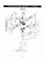
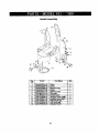
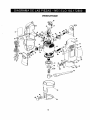
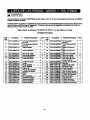
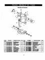
Main Unit
18
IA
WARNING J
When servicing
damage to your
use only CRAFTSMAN
Drill Preos.
mpiscement
parts.
Use of any _
parts may create
a HAZARD
or cause
Any attempt to repair or replace electrical parts on this Drill Press may create u hazard unless repair Is performed
by a qualified technician.
Repair service is available by contacting
your nesmst Sears Service Center.
Always order by PART NUMBER,
not by key number
Main Unit
Part #
Key #
1
2
01AT-000006-A0
01AT-000031-00
Part Name
Heat shrink tube 12 mm
Heat shrink tube 15 mm
6
7
8
9
10
02AE-000037-00
02AE-000057-00
02AH-000083.-00
02AH-000088-00
02AN-000012-00
11
12
13
Qty
2
3
Key #
33
34
2203-MA0001-00
2203-MA0001.00
Spindle locking
Collet nut
Rear beadng
Front bearing
Spindle lock spring
Brush spdn_l
He)_ nut
1
1
35
36
2203-MA001_
2203-MA0004-00
I/4" collet
1/8" collet
1
1
1
2
37
38
2203-MA000_c4X)
2203-MA0006-00
Brush retainer
Contact disc
2
2
1
39
2203-MA0007-00
Lock plate
1
02AS-00019 l-A0
02AS-000199A0
02AS-000206-A0
Case screw
Case screw
Screw
3
4
4
40
41
42
2203-MA0008.00
2203-MA000_00
2203-MA0010-00
Collet nut wrench
Sole plate holder
Sole plate
1
1
1
14
15
02AS-000260-00
02AS-000271-00
Machine screw
Machine screw
16
17
02AW-000040-B0
02AW-000048-00
E-ring
Serf-locking
1
1
1
50
55
60
9866-PA001_
9920-PA00t_-00
2203-PA0001-00
Cord anchor
Cord sleeve
Left case
1
1
1
18
21
22
23
24
02AW-000055-00
03AM-000072-00
03AM-000073-00
03AS-000081-00
03AT-000036-00
Retaining r_g
Stator
Rotor
Micro switch
Carbon brush
1
1
1
1
1
2
61
64
65
66
67
68
2203-PA000'_-00
2203-PA0005,.00
2203-PA00011-00
2203-PA0007,_0
2203-PA0008-00
2203-PA0009-00
Right case
Rubber handle piece
Rubber handle piece
Switch cover
Banner belt
Screw cover
1
1
1
1
1
2
25
31
03AW-000116-00
2203-505001-00
Power cord
Left label
1
69
2203-PA0010-00
Screw case
2
32
2203-505002-00
Right label
1
1
71
72
2203-PA0013-00
2203-PA0014-00
Brush cap
Brush case
2
2
ring
19
Part/it
Part Name
pin
Qty
1
1
_ff..
_A[o]D]=Im
Ii [:]_l Bllo_I0z0_
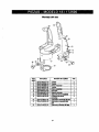
Handle Assembly
0
0
Key
#
1
Part Name
Part #
02AS-000201
-A0
Screw
2
3
4
5
02AS-000206-A0
02AS-000269-A0
02AS-000270-00
02AS-000271-00
Screw
Machine screw
Screw
Machine screw
6
7
8
9
10
11
2203-MA0010-00
2204-MA0001-00
2203-PA0009-00
2203-PA0010-00
2204-PA0001,-00
2204..PA0002-00
Sole plate
Handle holder
12
2204-PA0003÷00
Hexagon screw holdS,
Hexagon screw case
Right handle grip
Left handle grip
Soft grip handle
20
Qty
2
2
1
1
1
1
1
2
2
1
1
1
lv [o]m]= . ilE;! lll oIo]
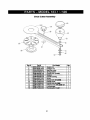
Circle Cutter Assembly
Key#
1
Part#
02AN-000017-00
2
3
4
5
6
7
02AN-000018-00
02AS-000258-00
02AW-000022-00
2206-MA0001-00
2206-MA0002-00
2206-MA0003-00
8
9
10
11
12
02AS-000272-00
2206-MA0005-00
2205-PA0005-00
2205-PA0006-00
2206-PA0001-00
14
15
2206-PA0003-00
2206-PA0004-00
PertNamo
Qty
Square nut
Hexagon nut
Machine screw
1
1
1
Spdng washer
Circular arm (mebic)
Washer
1
1
1
Handle
Screw
1
1
bushing
Circular arm (Impelt_)
Handle cover
Handle ball-like balm
Distance lock wi_ Oll_
Locking base
Round guide mount
21
1
1
1
pin
1
1
1
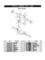
Router Assembly
Key #
Part #
Pert Name
1
2
3
4
5
02AG-000133-00
02A J-000009-00
02AN-000012-00
02AN-000013-00
02AN-000016-00
Guide bushing
TgUng base
Nut
6
7
8
9
10
11
02AS-000020-A0
02AS-000048-A0
02AS-000093-00
02AS--000258-00
02AS-000259-00
02AW-000029-B0
Screw
Machine screw
Base screw
Machine
M_.hine 1_rew
12
2205-MA0001-00
Square nut
SCrew nut
C-_n 9
Guide rod
Qty
Key#
Pmtal
i
12205-M_Om.
_0
4
13
1
14
2
2
1_
!220_0
16
2203-PA00_
I
17
2203-PA00_).
t
18
2205-PA00
3
8
19
21
2205-PA00
_- l0
2205-PA0014_
10'
2
22
2205-PA00
2
23
2205.-PA00
2
2
24
2205-PA00
22
2205_
]0
)0
10
!_,_ 10
_*._
Part Name
I
' Friction plate
(;It
Y
2
Ruler (metric)
Ru er (Irnperia)
Hexagon screw cover
Hexagon screw case
1
1
2
2
Upper base
Middle base
1
1
Lens
Handle
1
2
cover
Handle base
Locking disc
2
2
For repairofmajorbrandappliancesin your oum home...
no matterwhomade it' no matterwho sdd itT
1-800-4-MY-HOME
®
Anytime,
dayornight
(1-800-469-4663)
(U.S,A. and Canada)
www.seam.com
www.sears.ca
For repairof carry-inproductslikevacuums,_
equipment,
andelectronics,callfor the locationof yournearest
Seam Parts and Repair Centmr.
t400-488-1222
Anyt_e,dayornight(U.SJ_.
only)
www.seam.com
Forthe replacementparts,accessoriesando_mer'smanuals
thatyouneedto do-it-yourself,
call Seam PadsDirect I
TM
1-800-366-PART
6a.m.-
(1-800-366-7278)
11 p.m. CST, 7 days a week
(U.S.A. only)
www.sears.comlpartsdirect
To purchaseor inquireabouta SearsSense Agreement
or Seam MaintenanceAgreement
1-800-8274655
7a.m.-5
(U.S.A.)
1-800-361-6665
p.m. CST, Mon.-Sat.
9am.-8
Para pedirsen_io de mparacibna
4 pro. Sat.
Au Canadapour serviceen fian;ais:
domicl]io, y pare o_lenar piezas:
1-888-SU-NOGAR
(1-888-784-6427)
(Canada)
p.m. EST, M-F,
[email protected]
su
(1-800-533-6937)
www.sears.ca
® Reg_tered Trademark / m Trademark / _ Sentioe Mark Of Seam, Roebuck and Co.
m Man:adeFdi_ical
au Marca de Sen,,icio de Sears, RoeOuck and Co.
®MamaRegisbada/
"c Marque de oornmerce / *m Msrque a_ooe_e de Sears, Roebuck and Co.
23
© Sears, Roebuck and Co.
Manual
del propietario
CRAFTSMAN.
SIERRA
Modelo No.
183.172500
ADVERTENCIA:
Lea este manual y siga
todas sus reglas de
seguridad • instrucciones
de operaci6n antas de
usar esta sierra .
§
•
•
•
•
•
•
•
Instmcciones de seguridad
Accesorios
Montaje
Operaci0n
Mantenimiento
Lista de plezas
Castellano
Sears, Roebuck and Co., Hoffman Estates, IL 60179 USA
No. de parte 14k9277480001
Rev. 1 07/13/01
SECCION
P/_GINA
SECCI6N
PAGINA
........................................
2
Especificaciones del producto .............
Seguridad con herramientas el6ctricas..
Seguridad con la sierra .......................
Requisitos de elecb'icidad y seguridad...
Accesorios ......................................
2
3
4
5
6
Contenido de la caja ........................
Familiaricese con su sierra ...............
6, 7
8
Montaje y operacibn ........................
Mantenimiento ................................
Piezas de reparacibn .......................
Piezas y disponibilidad
de servicio ......
9 - 17
18
19 - 23
24
Garant|a
Ili
GARANTiA COMPLETA POR UN A_IO
Sears, si asi Io decide, reparar_ny reemplazar_ esta sierra sin costo alguno si la misma falla debido a
defectos de materiales o de fabdcacibn, durante un argo contado desde la fecha de su compra.
Envie esta sierra a un Centro de servicios de Sears para su reparacibn, o al lugar en donde la adquirib
para su reposicibn.
Esta garantia le da ciertos derechos legales, adembs de los cuales usted puede tener otros derachos
que cambian de estado en estado.
Sears, Roebuck and Co., Dept. 817 WA, Hoffman Estates, IL 60179
_IL
ADVERTENCIA
]
Cierto poivo causado
por el Iijado ei6ctrico, el aserrado, el molido, perforado
y dermts actividades
de la
construcci6n,
contiene productos
quimicos que (segOn el Estado de Canlromia) se sabe que causan c=tncer,
defectos cong6nitos
u otras lesiones al aparato reproductor.
Algunos de m
productos
quimicos son:
•
El plomo de pintums con base de plomo.
•
•
El silice crlstalino de los laddllos, el cemento y otros productos
El ars_nlco y el cromo de la madera tratada quimicamente.
de albahbrla.
El rlesgo al que se somete por exposici6n
varia dependiendo
de cmtn frecuentemente
haga este tipo de trabajo.
Pare reducir su exposici6n
a estos productos
quImlcos,
trabaje en un _,rea blen ventilada y use el equipo de
seguridad prescrito, tel como las m_scaras contra el polvo diseitadas
especlalrnente
para filtrar las partlculas
microsc6picas.
I
Capacidad del motor ...........
Amperios ........................
Velocidad (sin carga) .........
i];I
120V, 60Hz, CA
4.0 Am perios
30000 RPM
I=]=1m!-j o) =IlI e]nlEo;
Potencia del motor
Peso ........................
.....
HP (al m_mo)
3.75 kg
113
IA A°vE"TE"c=I
Use el protector de circultos adsouado pare evitar choques
el6ctricos, el Hesgo de Ii_endios
o daflar la siena
.
Esta sierra ha sido ensamblade
pare tmbajar con 110-120 volttos. Debe conectaNma un fusible de mtardo o a un
cortaclrcultos de 110-120 voltlos/15 empedos. Reemplace el cable de corrientl de Inmedlato si estl gastado, co,ado o dahado
de cuak:luler fonna pare evitar choquee o incendios.
Antes de user su siena , es vital que lea y que compmnda
lesiones sedas o debar la sierra .
estas ingles de segurldad.
SI no sigue estas reglas puede sufrir
Antes de usar su sierra es vital que lea y que comprenda
estas reglas
sigue estas reglas puede suffir lesiones serias o dahar la sierra .
LEA todo y familiarlcese con este Manual del
propietario CONOZCA
las aplicaciones, los limites y
los posibles riesgos de este herramiente.
2.
[_
SOLA UNA
16. NUNCA DEJE FUNCIONANDO
HERRAMEbrrA.
APAGUE LA HERRAMIENTA.
No
descuide la hen'amienta antes de qua se detenga por
completo.
NUNCA ale PARE SOBRE LA HERRAMENTA.
17. Puede sufrir lesioBes serias si la herramiente se
voltea o si tcca la herramienta de corte
involuntariamente.
ADVERTENC|A]
Busque este simbolo que idenlJfica las precaucion es
de segLtridad importentes. Signif'r,a IIPRECAIJClOINI
IMANTENGASE
ALERTAI
iSM SEGURIDAD
ESTA
EN JUEGO!
3.
USE I.AS GUARDAS
4.
NO SE USE EN AMIBIENTES PELIGROSOS
tales
como en sitios h0medos, mojados ni expuestes a la
lluvia. Mantenga el drea de tmbajo bien Huminada.
y mantengalas
5.
NO use herramientas el6cb'icas en presencia de
liquidos o de gases inflamables.
6.
MANTENGALIMPIAEL/_READETRABAJO,
_reas y las mesas de trabajo abarrotadas
accidentes.
7.
MANTENGASE
ALEJADO DE LOS NiI_Ios. Todos
los visitantes deben ester a una distencie segura del
_rea de trabajo.
8.
NO FUERCE LA HERRAMIENTA.
La misma har_ el
trabajo mejor yen forma m_s segura a la velocidad
para la que fue dise_ada.
9.
USE LA HERRAMIENTA
ADECUADA.
No fuerce la
herramiente o el acceserio a hacer un tmbajo papa el
cual no est_ dise_ada.
18.
en buen estedo.
NO SE ESTIRE Dr=MASI_DO. Mantenga un buen
sosteny su equillbdoen todo momento.
19. CUIDE BIEN SU HERIRAMENTA
Mantenga las
herramientas afladasy limpias para un rendimiento
m_s eficaz y seguro. Siga las instrucciones para su
lubricacibn y para el cambio de accesorios.
20.
REVISE
QUE NO HAYAN
PIEZAS
DAI_IADAS.
Antes de seguir usando una herramiente, una quarde
u otra parte daltada, la misma se debe inspecc=onar
para verificar qua funcione debidamente y que cumpla
su funcibn correspondiente.
Verifique la alineacibn de
las partes mbvites, el retdn de las mismas, su montura
/uCUalquier o_a condici6n que afecte su
ncionamiente segum. Se deber8 reparar o cambiar
toda guarda u otra parte que estd dafiada.
Las
inviten a los
21. DISPONGA IP4J TALLER A PRUEBA DE NI_IOS
usando candados, interruptores principales o
retirando las Ilavea de encendido.
22. NO usela hermmtente bajo la influencia de drogas
de aucono o de medicamentos que miten su
habilidad para usar la misma en forma segura.
23. UTILICE RECOILECTORES
DE POLVO en Io posible.
El polvo genarado pot ciertos materiales puede set
da_ino para su salud y causar incendios en ciertos
casos. Use slempre la herramienta en un _,rea bien
_._ntilada con la remocibn de polvo adecuada.
10. VISTA LA ROPA ADECUADA.
NO use ropa suelta,
guantes, corbatas, anillos, brazaletes ni joyas que
puedan engancharse
en las partes mbviles. Se
recomienda usar calzado que no resbale. Use un
protector para el cabello para retener el pelo largo.
11. USE UNA MASCARA O MASCARILLA
CONTRA
POLVO. Las operaciones deaserrado, code,
perforado y lijado producen polvo pellgroso.
Si no
CLAVlJAS Y LLAVES DE AJUSTE.
15. RETIRE _
Fbrmese el t'_bito de verificar que se hayan retJrado
las clavijas y las Ilaves de ajuste de la henamienta
antes de poneda en posicibn de "ENCENDIDO".
Las buenas prdctP._as de seguridad son la combinacibn
det sentido comt_n, de ester alerte y de saber cbmo usar
su herpamienta eldctrica. Papa evitar an'ores que le
puedan causar lesiones serias, no conecte su sierra
haste que haya leido y entendido las aiguientes reglas de
seguridad:
1.
de seguridad.
24.
EL
PROTEJA SEMPRE
LA VISTA
Toda herramienta el6cb'ica
puede lanzar partlculas
extratlas a sus ojos Io que los
puede dat_arpermanentemente.
USESIEMPRE
gates de seguddad (no anteojos) que cumplan con la
norma de segul_
ANSI Z87.1.
Los anteojos de uso
diario s_o tlonom Ilntes que resisten a los golpes. NO
SON 9alas de le0udded.
Seapa dispone de galas de
seguddad.
12, DESCONECTE
LA HERRAMIENTA
DE LA FUENTE
DE CORRIENTE
antes de hacede servicio y cuando
cambie los accesorios teies como las hojas, las
brocas, las sierras, etc.
13. REDUZCA EL RESGO
DEL ENCENDIDO
INVOLUNTARIO.
Verit'que que el intenuptor est6 en
la posicibn "APAGADO" antes de enchufar la
herramiente a la corriente.
IA
14. SOLO USE LOS ACCESORIO$
RECOMENDADOS.
Busque los accesorios recomendados
en el Manual
del propietario. El uso de accesorios inadecuades
puede causede tesiones y de_ar la herramienta.
ADVERTENCIA
]
Los anteoJ_
o 9das que no cumplen con la norma
ANS_ Z87.1 IWedm
¢ausaurle tesiones severas al
roilq)eme.
GUARDE ESTAS INSTRUCCIONES COMO REFERENCIA
3
10. FUE SEMPRE
_A
ADVERTENCIA
J
ABRAZADERAS
MIENTR.,I_(N)RTE
Para su segurldad,
no enchufe su sterra nl Intente
user cualquler accesorio
que no est6 ensambtedo
e
instatado completamente
seg,',n eetas instnJcclones,
y hasta no haber leido y entendklo este Manual del
propletado.
Puede sufdr el rlesgo de leslones
estas regtas de segurklad.
1.
2.
sertas
para operar la herramienta.
11. NUNCA 80_rENGA
LA PEZA DE TRABAJO CON
UNA MANO mlentras opera la herramienta con la otra
mano.
12. NUNCA COLOQUE
LAS MANOS EN EL CAMINO
DE LA SIERRA NI DEBAJO DE LA PIEZA DE
TRABAJO.
si no sigue
USE PROTECTORES
PARALAVISTA.
Esta
herramienta de alta velocidad har_ saltar partJculas
de la pieza de Vabajo durante su opemcibn.
Aseg0rese que sus gafas de seguridad tengan lados
protegidos.
USE UNA MASCARA
PARA EL ROSTRO
O
CONTRA EL POLVO adem:_s de gafas de seguridad
si ta operacibn de code o de fresado es polvorienta.
AsegOrese que su 8tea de lmbajo est_ bien ventflada.
3.
4.
PROTEJASUS
prolongados.
NUNCA
OIDOS,
en especial
durante trabajos
13. NUNCA _A
LA BROCA TOQUE
USE BROCAS
ROMAS
O DAI_tDAS.
broca puede engancharse
perder el control.
se pueden
recalentar
VERFIQUE
TRABAJO
SIEMPRE QUE LA PIEZA DE
NO TENGA CLAVOS U OBJETOS
y romper.
14. SIEMPRE IK)_rENGA
LA HERRAMIENTA
AMBAS MM4OS CUANDO LA ENCIENDA
OPERE.
El torque del motor al encenderce
hacer que la herramienta se retuerza.
15. APAGUE
16. SOSTENGA
Y
7.
DEJE UN ESPAClO BAJO LA PEZA DE TRABAJO
pare que la broca se mueva. Nunca coloque la pieza
de trabajo sobre superTK:ies duras como hormigbn,
etc. La broca puede saltar o romperse cuando toque
otra superficie que no sea la que se est_ cortando.
EL MEDIDOR
LA PROFUNDIDAD
DEBIDA.
fAEIR_RE
LA HERRAMENTA
POR
LAS SU_IES
AISLADAS DE AGARRE DEL
CUERPO
DIE LA MISMA cuando e)dsta la posibilidad
17. CUANDO
DE PROFUNDIDAD
A
I'IAGA ABERTURAS
PARA TOMAS
DE
CORRIENTE
EN PIRCA usando el tomacorriente
como guia, haga siempre el corte en sentido contra
las agujas del reloj. La tendencia natural de ia
herramienta a Urar hacia la izquierda causar_ que se
acerque m_ls a la toma de corriente, dando un corte
m_Js preciso.
18. NUNCA RImGtJIESTE LA HERRAMENTA
HASTA
QUE LA 8IIBIRA SE HAYA DETENIDO
POR
COMPLETO,
La broca en movimiento puede tocar la
superficie y dmmontrolarla.
Use la herramianta
con el medidor de profundidad en posici6n plana
contra la superficie de trabajo para controiar mejor la
herramienta.
NUNCA USE LA HERRAMIENTA
SIN LA BANCADA,
EL ASA DE PRECISION O LA BASE DE FRESADO
colocados
LOS CORTACIRCUITOS
puede
corriente hattt que pase corriente a las partes de
metal e_puestas'de
la herramienta, y le dar_ un
choque ei_ctrico al usuarto.
NO USE ESTA HERRAMIENTA
PARA PERIFORAR
AGUJEROS.
La misma NO fue diset_ada como un
taladro.
9.
TO006
CON
Y LA
de que la siena toque cables el6ctricos ocultos o el
cable de la herramienta.
El contacto con cables con
6.
FUE SEMPRE
en la pieza haci6ndole
Las
EXTRA,lOS.
Si la broca choca contm un clavo,
saltar_ a un lado y puede romperse.
8.
LA HERRAMIENTA
CUANDO
LA PIEZA DE TRABAJO.
La
RETIRE TODD8 LOS FUSIBLES del ;_rea de _abajo
cuando haga cortes en las paredes 0 en _reas ocultas.
brocas dal_adas se pueden romper repentinamente.
Las brocas romas pueden sobmca_gar el motor,
codar m;_s lento y set diflciles de controiar. Tambi_n
5.
LA PEZA DE TRABAJO CON
PARA MANTENERLA
FIRME
_sto dejar_ libres ambas manos
y fijados debidamente.
19. NUNCA TOQUE
LA BROCA
INMEDIATAMENTE
DESPUI-._
DE UIMd_ILA. La broca estar_
caliente pan= manipulada con tas manos
desprotagidaa y le quemar:_ los dedos.
20. VUELVAAAPRETAR
muy
$1EMPRE EL MANDRIL DE
PINZA Y TOOOS LOS AJUSTES antes de arrancar la
herramients US cambiar la broca o un accesorio.
Las brocas _fk)s ajustes flojos pueden hecer que la
herramienta le mueva sorpresivamente,
heci_ndole
perder el control y pudiando causede lesiones por la
broca o al _
la herrem ienta.
GUARDE ESTAS INSTRUCCIONES COMO REFERENCIA
_1k'11f;1LMI---. .....
"
--
Esta sierra Uene un aislamkmtodobie para protegedo
contm choquesek_ctr_.os.
Verlflque
que _m cable de extansl6n
est6 en buen
eMado.
Cuando use un cable de extensibn, asegOrese
de que el rnismo l_eda transm_r la con'Jente que requiem
la henamienta.
Un cable de calibre inferior har_ que
IA W. NC.I
Las herramlentas
de elslamlento
dome ttanen
un
enchufe potadzado
(una hoJ8 (is _
ancha clue la
otra). Este enchufe s61o celza de una forma en el
tomacordentes
poladzado.
Si el enchufe no calza
blenen el tomaconlentes,
velMe el enchu_.
Sia
pesar de Io anterior
no calza, €ontmcte a un
electrielsta
califlcado para ClUe Instale un
toma_)n1_
potadzado. No altwe el enchufe en
forma elguna. Ela_lemlento dome e_
la neces_ad
de tener un cable de corriente de tres ca_es con toma a
tlerm y un sistema de conte_e con toma a t_m-a.
Evllmque su cuerpo toque tas superficies con toma a
tlerra tales como tubedas, radladores, estufas y
refrlgeradorel SI su cuerpo haca tkrra, existe mayor
riesgode m_l_r un clloque ek_hlco.
No exponga las herramlentas elk:trlcas a la Iluvla o a
la humedad. El agua denVo de una henamienta ek_hica
a_
el riesgode recibirun choque el/_V_o.
No meltrata el cable. Nunca use el cable psra Ilevar la
herramlenta nl tire del mlsmo pant desenchufada.
Mantanga el came aleJado del calor, el acelta, los
obJetosafll_
y las piezas en movimiento. Los
cablesder_clos aumentan el 0_mgo de d'mques ek_,_cos.
celga el voltajo de Is linea, Io que han_ que falte energia y
el mlsmo se recah_.e.
La _
de abajo muestm el
calibre _
mgGn Is long#ud del cable y su capack:lad
nominal e_ ampedos. Si tiene dudes use el cable m_s
gmnde que le Mp_ A menor n0rnero de celibm, mayor
ser_ el groso( del cable.
Asog0rese
de ClUe =u cable
est6 blen
Utillce un cln:tlBo eHtctrlco separado para sus
hewamlentlm
eNi_lrtcas.
Los cables de eele cimuito
deben ser elaml_m
de calibre superior a 14 y el mismo
debe estar protegido con un fusible mtardedo o con un
cortacimuitos de 15 amperios. Antes de conectar la
hermmlenta ekk:Mca a la fuente de cordente, vedfique
que el intemJptor est6 en poelcibn de "APAGADO" y que
la fuente de colltente sea hamisma que se indica en la
placa de datos. Sl el motor fundona a un voltaje menor,
puedesu_ der_.
Repam o relx)nga
Inmedtalbo.
Use un cable de extension
para extarloms marcado
con "W-A"o con "W" cuando opere una hemlmlenla
elk_lca
en exterloms.
Est0s cables est6n des_caOos
pare usos exledoms y mducan el desgo de choques
ek_trico$.
de extensi6n
r.elbleado yen bush estaOo. Antes de usarlo, mponga
tode cable de exllm_sk_ dafiado o haga que un electdcista
calificado Io relpem. Proteja su cable de extensi6n _ontra
los objetos afhdos, el calor excasivo o las _reas
h0medas o mojadas.
los cables
de extensl6n
dahados
de
Escoja el _
y la Iongitud adecuados del cable de
extansi_n empimndo la table de abajo.
CALIBRE II_
pARA CABLES DE EXTENSION (AWG)
(Um_ ex¢luslvo
de 12 volttas)
Capacidad
Aesg0rese
slempre de que kl toma est6 polarizada,
tiene dudas, haga que un elecMcista
calillcado ia
revise_
Wt arnpedos
Longitud total en :)les
Si
M;_sde
0
6
10
12
No.de
6
10
12
16
27
50'
18
18
16
14
16
16
16
12
100'
150'
16
14
14
12
14
12
Nosea_ica
I
Mantenga M _
de extensi6n
fuem del
trabajo.
Ul=iqam ei cabta de modo que no
con la _
de ll'_:_o,
la herramtanta
ni
cuaiquler olro abJk_o mlentras usted esM
mmamient8
d_:trlca.
_rea de
se enganche
con
usando la
A_E_RIOSDISPONIB_S
DESEMPAQUE
LA CAJA
Use
s61o
losaccesodos
recomendados
palm
esta
sierra
espiral.
Siga
lasinstrucdones
_
vlemm con
los accesorlos.
El uso de acce_xlos
inadecuados
puede
causade
lesiorms
ai usuario
o dahar la sierra
Y VERIFICACI_N
DEL CONTENIDO
DE
IA ,OW T.C=
I
Si falta algtma pkllli o si la misma esUi dahada, no
conecte la skllfa a la fuente de corriente hasta volver
a colocar
la _
tMlante
o dahada
y completar
el
esplral.
montaJe.
Visite el Departamento
de Herramientas
de Seam o vea
et Catilogo
de herramlentas
ekk:blcas y de mano de
Sears 10amenconVar el surtido de accesodos sugeridos
pare esta herramienta:
Desempaque cukildosamente la sierra y todas sus
partes. _
oon la tabla de '_3omponentes0e La
sierra "de abajo.
NOTA: Las _
se ilus_an en la p6gina 7.
•
Brocas espimles de code de 1/8"
•
Accesorios de bricolaje de 1/8" pare herramientas
giratodas
;" Sierras
_- Pulidores
_, Lijas
:v Muelas
I&
•
I
Nunca use _
naft_ acetona, dlsolvente
esmaltes u o(_s ImlventN
altamente volltlles
Ilmplar la siena , _n el IBn de evitar Incendlos
macclones
t6das.
Casi todas hasfresas con vAstago dell4"
COMPONENllES
LETRA
IA
J
Use s61o los accesorios
dhr4hados
para evitar leslones serias o dahos
para esta sierra
a hi herramienta.
No uffllce ningr, n accesodo
a menos que haya leido
pot compieto las Instrucciones
o el Manual del
propietario
de tal accesodo.
DE LA SIERRA
DESCRIPCION
de
para
o
CTD
A
Sierra
1
B
C
Asa de predsidn con bancada
A(x:m0odo de bancada de manos
libnm
1
1
D
ACCm0flO de sierra circular
1
E
_
drcuW
Accelmdo
1
,
F
pare instalar la sierra
de base de fresado
1
G
MangtJo
1/8"
de mandril de pinza de
1
H
Mal_uito
1/4"
de manddl de pinza de
1
I
J
K
Siena _
pirca de corte lateral
Maw) para mandr# de pinza
So_
de Ilave para manddl de
p_z=
1
1
1
L
M
Manual del propietano
Estuche de tmnsporte
1
1
A
¢
Periila de
_
AJ_-az_era
euiecien
L.---,_
_
..i-
de rrmntaje
io
Perilla de
_ncada
Perilla de puMo
de _vote
M_:lidor de
ajustar la altura
rnontaje
MONTAJE
Retire el enchut_
de la fuerre
de cm_lente
antes del
montaJe, cambio de accesodos
o de la sierra y antes
de hacer los ajustos.
E_
_ci6n
de ugurichKI
le
ayuchw6 a evhr el encendido
accidental
de la
herrlmlenta,
que podda causar luiones
severaa.
INTERRUPTOR
DE ENCENDIDO
I APAGADO
DE BROCAS
PARA
I..4, SIERRA
Siga pulsendo HACIA ADENTRO el bot_ de cien-e
del v_tago mlentras hace gimr la tuema det mandril
de pinza en serllido contra kas agujas del reloj con la
Ilava del manddl de pklza (3). Gins 2 o 3 vueltas la
tuerca del manddl de pinza para aflojarlo.
3.
Esta sierra est_ equipada con un intmTu_or deslizante de
ENCENDIDOIAPAGADO
(1) ubicado a un costado de la
hernsmienta (vet la fig. 1).
Si la herramienta
Uene una broca ya instalada, retinsla.
Inserta la broca nueva (4) en el mandril de pin__a.
Inserte toda la broca en el mandril de plnza y
luego iMiquaia enlre 111e"y tl1". Esto crea un
espacio vado enl_e el v6stago del motor y ia
broca ClUe _
clue la mhsma se recaliente.
Antes de apretlr el mandril de pinza sobre la
broca, verUklue que so puedan ver todos los
canales de hi broca (las partse adas) fuera del
mandlll de plnza. SI el mandril de pinza se clerra
sobre los cimales de la broca las mlamas se
pueden _
y pueden causar dahos.
Fig. 1
Cuando la bnsca est6 bien colocada
en el manddt de
pinza, pulse el bok_ de cierm del v_Lstago y haga
girar la tuema del mandril de pinza en sentido horario
con la mano tanto como sea posible.
1. Desliceel bot6n hacia anlba pare ENCENDER la
hermmienta.
2.
Deslice el botbn hada abajo para APAGAR
hen'amienta.
MONTAJE
DE BROCAS
6.
Apriete bien la tuema del mandril de pinza con ia Ilave.
la
PARA LA SIERRA
Las supedlcles
cortantse de la bro_
para la elerra
y
de ia fTlSa son muy IIIosas.
ManipGlelas
con cuidado.
Utilico la Uave 10am el mandril de pinza loam insertar la
bnsca de la sierns . La flare se encuentra en su soporte,
qado el cable de cornente.
1.
Pulse el bot6n de ciems del v_ago
(1) y gim la
tuema de cierm del manddl de pinza (2) en sentido
horado con la otto mano hasta (lue el botdn de cierm
calco en su sif_o, evitando qua el vlrmtago gins (vet la
_g.2).
Fig. 2
RECAMBIO
DEL INSERTO
DEL MANDRIL
MONTAJE
DE LA BANCADA
Continuacldn
DE PINZA
Las brocas pare esta hen'amienta quedan fijas pot"medio
de la tuerca del mandril de pmza (1) y del mandril de
pinza (vet la fig. 3). La herramienta viene de f_bdca con
un mandril de pinza de _/e" (2) que se usa para soelener la
broca . Un mandril de pinza adicionel de _A"(3) viene
incluido para sostener has brocas PEQUEI_S
con
vdsta o de _R.
NO use b _
de mnos
control Ilmitldo _
hacer perder el _
suhtr lesionol
DE MANOS
libra
le ofrece _
y aumentar
LIBRES
con fr_as.
-
B
acceaorlo
le puede
la poslblndad de
Retire ha pedlM de sujeck_ del accesorio (t) de la
base del cu_
de la sierra (vet la fig. 4). Desnco la
abrezadem de monfaje de habancada de manos
libres (2) sobre la parte inferior del cuerpo del motor
(3) basra que el odficio de montaje (4) so afinee con el
orifiP__oen el cuerpo del motor.
NOTA: La leno0eta en el lado de habande
de la bancado (:lobe calzar en harenura
conespondiwVM
<In el cuerpo del motor.
de montaje
3
4
Fig.
Vuelva a ineadar la penlla de sujecibn en el cuerpo
del motor y aWifltela bien.
3
Cbmo cambiar un mandril de pinza de un tamafio 10orel
otre:
1.
Retire la broca de ha herramienfa,
2.
Continue girando la tuerca del mandril de pinza en
sentido conbario a has agujas del reloj hasta que ha
pueda retJrar del v_stago del motor (4).
3.
Saque el mandril de pinza del vdstago del motor y
cdmbielo por el otto mandril.
NOTA: Ambos mandr#es de pinza tienen extremos
id_nUcos, pot Io que se pueden celocar en cualquier
1
2
senfido sobre el vdstago del motor.
4.
Vuelva a cok)car la tue_ca de/mand_
apri_tela ligeramente a mano.
5.
Instale la nueva broca tel como se indica en
MONTAJE
9.
DE BROCAS
de pinza y
PARA SIERRA
Fig. 4
AJUSTE DE LA BANCADA DE MANOS UBRES
en la pdgina
NOTA: Si el mandril de pmza se apdeta sin una broca
dentro del mismo, la aberture del mandril se puede reduCir
y dificultar la montura de has brocas. Cuando guarde la
her,remienta sin brocas en el manddl, deje floja la tuema
del mismo.
MONTAJE
DE LA BANCADA
DE MANOS
Ajuste hapmftmdidad de la bancada de macos libres
aflojando ha pedla de/medidor de profundidad (5) y
deslice habexlcade (6) hacia adentm o hacia afuera
segdn Io requiom (vet la fig, 5).
NOTA: Fije el moeldor de profundidad de forma que la
broca _
de _1 bancada 118"m;_s all_ del
gmsor del _
que se corte. Por ejemplo, si coda
pirca de 51s", habroca debe sobmsalir =A" mds all_ de
ha bancada.
UBRES
La bancada de manos libres est& dise_m_ para el corte
bd,elco de manos libres con la broca , Es ideal para abdr
los orificios 10am tomacoaJentes
en pirca.
2.
lO
Apriete bien ha_
del modidor
de profundidad.
AJUSTE
DE
LABANCADA
DE
MANO8
UBRES
ContJnuacidm
3.
4. Ajuste la Wofundidadde la bancada tal como eft la
fig. 5.
Antes de comenzar el corte, vedfique la profundidad
de la broca, y que kJ bancada est6 en _ngulo recto
respecto a la misma y est6 bkm sujeta. Vuelva a
revisar el mandnl de pinza para asegumrse de que la
broca est6 _
sujeta.
5.
Apoye el bolde de la bancada sobm la pmza de
tTabajo con I! boca a un _ngulo de unos 45° (ver la
fig. 6).
NOTA: NO pennita que la broca toque la pieza de
trabajo hlta
_
que el interruptor es_ ENCENDIDO
lenga la velocid_l _lda.
y la
Antes de ENCENDER
ia herramlenta,
uegOrese
de sostefleftla flnnemente
con ambas mano_
El
_5
torque del eocendldo
puede
herrandenta
m retuerza.
Fig.
_k
5
ADVERIENCIA ]
_,Ya ley6 "SEGURIDAD
CON HERRAMIENTAS
ELI_CTRICAS",
SEGURIDAD
CON LA SIERRA "y
"REQUISITOS
DE SEGURIDAID" en las I_Iginas 3, 4
y 5 de este Manual?
Si no Io hizo, hlgalo antes de
operar esta sierra . iSu seguridad
depende de ellol
Carla vez que use la sierra , debe verlflcar Io
siguiente:
1. Que ei cable de la sierra no est6 dahado.
2.
3.
4.
\
Que la broca sea la commta para el material.
Que la broca e_t6 dlada,
em I_mm estado y
blen monlada y suJeta.
El uso de galas de seguddad y mascadlla
contra el polvo.
El no cumpllr
aumentar
estas reglas de seguddad
puede
su rlesgo de sufrlr lesiones.
PRACllQUE
LOS CORTES
MANOS UBRES
CON LA BANCADA
DE
Antes de intentar tmbajar en u_nproyecto, t6mese el
tJempo de prac_car varios cortes con su sierra
Use
material de desecho id6ntico al material que usard en su
proyecto.
1.
Dibuje un paten igual al de su primer proyecto en el
material de desecho.
2.
Monte la bancada de mano6 lit)ms tal como en la fig.
4.
3.
Ins(ale la broca en el rnanddl tal como en la fig. 2.
11
hacer que la
PRACTIQUE
LOS
CORTES
MANO8 LIBRES
CON LA BANCADA
DE
6.
Pass el intemJptor a la posicidn de ENCENDIDO.
7.
Cuando el motor alcance la velocidad debida, mueva
lentamente ie hefpamienta a una po_ick_ derecha,
dejsnde que la broca corte la piez.a de trabajo (vet ie
fig. 7). Cu_
la herpamienta est,) demcha y la
broca hays perforado la pieza de trabajo, mueva
ientamente la hen'amienta en santldo
horatio con
Cuando abra un odficio en una superficie vertical, evite
terrninar la aperture en el rondo del orirmio. Comlance y
termine siempm an el "tope" del mismo papa que la pieza
cortade no caiga _
la broca en movimiento. APAGUE
siempre la henwrlilnta
antes de sacada de la pieza de
tpabajo.
APERTURA
EN PIRCA
AI completer el corte, APAGUE
a que se detenga per complete
de tpabajo.
la herramienta, espere
y sdquela del material
1.
PELIGRO
Cuando flje ie pirca, no coloque clavos o tomillos a
rnenos de 12" de la caja. Esto evitald que la pirca se
deforme debido a la pmsk_n.
I
No Intente sbdr orlflclos pars tomacorrlentes
en plrca
hasta que:
1. Se hays Interrumpido
toda Is eiectrk:idad
a los
cables eldclricos
circundsntsa,
blefl sea
APAGANDO
el corlacircultos
o retlrando los
fusibles.
2.
Hays leldo las Instrucciones
en la ptglna
sigulente selbm "APERTURA
DE ORI_S
TOMACORRIENTES
EN PIRCA _.
CONSEJOS
Antes de instalar la pirca, empuje los cables tan atrds
de le caja como sea posible pare que la broca no los
corte cuando abra el odficio.
Ames de colocar la Idmina de pirca sobm la caja de
electncidad, marque la I&mina tan cerca del centro de
la abertum de la caja c0mo sea posibie. La mama
deber6 ester del lade de la pirca que est_ frente a
usted.
Fig. 7
I,_l,
PARA TOMACORRIENTES
],_
PELIGRO"
]
No Intente user m
herramlenta
pars hscer aberturas
cerca de cualquler aparato o aperture que tenga
cables con contralto o sol=re cualquler paled que
tenga cables ellk:Wicos detrls de Is misma. AI entrar
on contacto con un cable con €ordente, le broca
transmiti_
le _
a hi herramienta,
som_iendo
al usuarlo al riesgo de suffir un choqus
eld_-trico.
APAGUE el cortacircuitos
o retire los
fusiblsa pars descmwctar
el circulto el_tctrico en el
#rsa de b-abaJo. _
slempre la hermmienta
por
su cuerpo alslado ¢uando trabaJe en iirsae donde
exists la poslbilldad
de tocar cables con corriente.
Protejs siempre su vista cuando use esta herramienta.
una pmsk_n pamja 10am hacer el corte.
NOTA: Corte siempm en senUdo horatio salvo
coande abra odficios 10am los tomaconientes.
8.
DE _
Inserte la siena y monte la bancada de menos libres
tel como lo indlcan las pdginas 9 y 10 de este Manual
del propietado. Ajuste la profundidad de code papa
que la broca sobmsalgs 'le" m;_s ell_ del glosor de la
pirca.
5,
PARA
DE CORTE
Sostenga finnemente
la hen'amienta con ambas
manos y ENCI¢:NDALA.
Introduzca la broca a trav(_s
de la pirca en la marca que indica el centro de la caja.
La fig. 8 musatra q
La acck_n giratorla de la broca hace que la hemamienta
tire un poco hacla la izquierda cuando hace los codes.
l_as vadac_ones natupales de ie madem hacen que ie
hermmienta "camine'.
Ests tendencla sa exacerba
cuando sa splice mucha presibn a la broca. El code mds
lento ie permite un mejor control.
Demaslada presibn o
un code muy r_pido aumentar_ la temperature de la broca
y acortar,_ su dupaci6n.
12
Fig. 8
i'd P_
APERTURA
DE ORIFICIOS
EN PIRCA - Cor_nuaci6n
m
PARA TOMACORRIENTES
MONTURA
6.
Mueva la broca tentamente
a la derecha haste que
sienta y oiga que hamisma toca el interior de la caja.
DE PRECISION
El asa de preciel_m ut_ dios_ade para cuande se desea
toner un control pmdso del movimiento de la herramieota.
Este asa cbmoda =m puede usar con cualquiera de las
dos manos.
Saque la broca Io suficiente pata podeda deslizar
sobre el horde de la caja. Cuando la broca est_ fuera
de la caja, vuelvela a inserter completemente al lado
del horde extemo de la caja.
1.
Mueva la herramiente hacia ardba con una presibn
Ilgera hada el centro de la caja. Cuando siente que
la broca elcance la esquina superior demcha de la
caja, mu(T)vala hacia abajo hacia el centre de la misma,
aplicando una presibn ligera.
Continue moviendo la herramieflte
DEL _
Saque la penlla de sujed6n de accesorios (1) de la
base delcuelpodel
motor (verlafig. 10). Montela
abrazadera del aim de precisibn (2) sobre la porte
infedor del cuerpo del motor (3) haste elinear el
odfido de montura (4) con el orirmio del cuerpo dot
motor.
NOTA: La leng0ete en el lade de la abrazadera del
asa de precisi6n debe quedar inserte on la mnum
correspondiente en el cuerpo del motor.
alrededor de la
caja en sentJdo contrario alas agujas del reloj
mientras haos una presibn liviana hacia el centro de
fa caja. AI completar el orificio de la caja, APAGUE la
herramiente y s_quela del odficio.
2.
Vuelva a inNrtar haperilla de sujeck_
al cuerpo del motor y apri6tela bien.
de accesodos
10. El odficio terminado del tomacolTientes quedar&
rematedo en forma limpia y precisa (vet lafig. 9).
j_
2_
Fig. 10
AJUSTE DE LA BANCADA DE MANOS UBRES
Fig. 9
1.
Ajuste la pf_undidad de la bancada del asa de
precisk_ _
la perilla del medidor de
profundidad (5) y deslizando la bancada (6) hacia
adentro o hada afuera segt_n se requiem (vet la fig.
11).
NOTA: Regule la profundidad do mode que la broca
sobreselga 11==_
all_ del grosor del matedal de
corte. Pot ejemplo, si coda madera de pino de 3/4", la
broca debe ii0brualir
71e"rods all& de ia bancada.
2.
Aprtete _
NOTA: Mueva siempre la broca en sentJdo contrario a has
agujas del reloj ak'ededor de ia osja del tomacontentes.
La tendencia natural de la broca 8 moveme a la izquierda
faciliter_ cortar rn_s osrca de la caja.
13
II pedlla del medidor de profundidad.
_Ki]_r_ll=l
AJUSTE DE LA BANCADA
Continuaci6n
3.
DE MANOS
LIBRES
h_ [o]_
-
5.
Antes de iniciar el code, revise la pfofundidad de la
broca, varifique que la bancade est6 perpendicular a
la broca y que estd bien sujeta. Vuetva a revisar el
mandnl de pinza para vedficar que la broca est6 bien
sujeta.
[_]_1
Ajuste el radio del ¢ortador de cimulos atlojando la
penlla punhgude
de pivote (6), deelizdndola al radio
correcto _ CIft:ulo y volvidndola a apretar en el sitio
deseado.
NOTA: Revise el ajuste del radio dei cortador de
circulos _
hasta la _
el mismo desde el punto del pivote
extador de la broca .
Fig. 11
::rm
MONTAJE
DEL CORTADOR
DE CiRCULOS
El accesoriopare cortarcircu_oses idealpara cortar
circulosprecisos. Este cortador de c[muk)spuede
montarsetantoen la bancada de manos libms como en la
bancada del asa de precisi6n. La iluslmck_nmuesVa el
cortadorde cimulosmontadoen la bancada de manos
libms.
1.
Instale la bancada de manos libres a la henamienta
como se muestra en la p6glna 10 de este Manual del
propietario.
Introduzca el inserto [0am rnontar el cortador de
cimulos con rosca extema (1) el rondo de la bancada
(2) (ver la fig. 12).
NOTA: Vedfique que la "D" moldeada del inserto
caiga dentro de la "[3" qua le ¢orrt_x)nde
en la
bancada.
3.
Coloque el odficio de montura del cortador de circulos
(3) sobre el inserto de montura (tel cortador de
circulos con rosca externa.
NOTA: Vedfiqua que el pin afUado de pivote (4)
apunte lejos de la henantenta.
4.
Enrosque el disco de montura del cortador de circulos
con rosca intema (5) al insedo de montura con msca
extema y apddtelos a mano.
NOTA: No apriete demasiado
las partes de pl_stico
para montar el cortador de clmulos. Ap_telas
sblo Io
neossario.
'
4/
s
Fig. 12
14
=1W
.._----']Z4f'--I|I----:L
OPERACI_N
--
DEL CORTADOR
-
__._--
DE CiRCULOS
OPERAP.J(_
Continuack_
5.
antes de camblar los accesorlos,
hacer los ajustes.
camblar
la broca
Antes de ENCENDER
la hermmMnta,
revise y
aseg,',rmm de que la broca y todos los retenes
accuodos
est6n blen suJetoL
y
DEL CORTADOR
Pase el intem_or
a la posick_
-
de ENCENDIDO.
Cuando el motor Ilegue a la velocidad debida,
endereoe lentamente la henamienta y el montaje del
cortador de drculos, dejando que la broca per_m en
la pieza de tlabajo (vet la fig. 14). Tenga cuidado y
mantenga la punta de pivote ubicada en el centro del
circulo que debe codar. Cuando se enderece la
herramiln_
y la bfoca haya traspasado la pieza de
trabajo, mueva la herramienta lentamente en sentido
horadlo con una presk_n sostenida para hace_ el corte.
ContinOe coftando el c[rculo, manteniendo la
de
Marque el centro del circulo que desea cortar en la
de trabajo y perfore un odficio piloto de 6 mm o
de_l_-.
hen'amienR demcha y girando alrededor del punto de
pivote del cortador de cimulos.
Ajuste la profundidad de la broca _ls" n_s all6 del
grosor del material que va a cortar.
7.
Ajuste el radio del codador de circulos aflojando la
perilla punfiaguda de pivote, desl_ndola
al radio
con'ecto del circulo y volvidndola a apfetar en el sitio
deseado.
NOTA: Revise el radio deJ oortad(x de ckculos
AI completw el co_'te, APAGUE la herramienta, espere
a que se detenga pot completo y ret{rela de la pieza
de trabajo.
mid_ndolo desde el punto del pivote basra la parte
exterior de la broca
Apoye el borde de la
trabajo, con la broca
13). tnserte la punta
ckculo6 en el odflcio
circulo.
DE CiRCULOS
bancada sobre la "pi_ezade
inclinada a unos 450 (ver la fig.
de pivote det cortador de
piJoto pedorado eft el centro del
NOTA: NO permita que la broca haga contacto con la
pieza de trabajo antes de habet ENCENDIDO
el
interruptor y de que la herramienta alcance la
velocidad debida.
Fig. 14
Fig. 13
15
AJUSTE
Elaccesout0
defresedo
conviede
asusierra
enun
fresador
debdcolaje
capaz
deuser
fmsas
peque_s
con
v_stago
de114",
asicomo
laIxoca
de code. Su base
inclinable es ideal pare los codes biselados.
Desconecte
la herramlenta
de la fuente do conlente
antes de camblar los accesodos,
rambler la broca y
DE LA PIROfUNDIDAD
DE LA FRESA
La profundided del _
se controla deslizando la base de
fresedo hacia antba o hacia abajo sobre las mangas de
ajuste.
1.
Afloje ambas pelilas de ajuste de la altura (1)
desenrosc_ndolM
en senUdo contm las agujas del
reloj (ver la fig. 16).
2.
DesHco la base de fmsedo (2) bacia an'iba o hacia
abajo basra alcanzar la profundidad de code deseada.
3.
Cuando obtenga la profundidad de code dessede,
vuelva a apretor las penllas de ajuste de la altura.
hacer los ajtmtse.
Antes de ENCENDER
la herramlenta,
seeg,',rese
accesoflos
de qua la broca y todos
est_n bien sujetos.
MONTAJE
DEL ACCESORIO
revise y
tos retenes
de
DE FRESADO
1.
Retire cualquier accesodo ya montado en la
herramienta.
2
Retire la pedlla de sujecibn de accesodos (1) de la
base del cuerpo del motor de la siena (ver la fig. 15).
Pulse el botbn de clerre del vi,stago del motor (2) en
la parte de atr_s del cuerpo del motor (ver la
ilustmcibn insertada).
NOTA: Gire el mandril de espiga mienbas pulse el
botbn de cierre del v_stago del motor hasta que el
botbn calce en el odf_o del v_nstago det motor.
Fig.
AJUSTE DE LA INCUNACI(_)N
FRESADO
Des,co la abrazadera de montaje del accesodo de
fresado (3) desde el fondo del cuerpo del motor (4)
hasta que el odflcio de montura (5) se alinee con el
onficio de la abrazadera de montaje.
NOTAS: El odficio elevado
de la abrazadera
16
DE LA BASE DE
Se pueden hacer cortes biselados con la broca
la base de fresado al _tngulo deseado.
1.
de
inclinando
Afloje ambas perks
de ajuste del bisel (3)
desenmsc&ndoise unas 2 veces en sentido contra
las
agujas del rek)j (vor la fig. 17).
montaje se desHzard sobm e_ botc_n de cierm del
v&stago del motor s_o si el bot6n ha sido pulsado por
completo y ha calzado en el v&stago del motor.
2.
Incline la base
La leng0eta en el lado inverso de la banda de montaje
de la base de fresado deba entrar en la ranura
3.
Vuelva a apretar
correspondiente
4.
Verifique el _ngulo enb'e la base de fresado y la brona
para aseguranm que el _ngulo sea el correcto.
del cuerpo del motor.
4.
Vuelva a insertar la pedlla de sujeclbn de
accosodos en el cuerpo del motor y apri6tela bien.
de fresede
(2) al &ngulo deseado.
ambas pedNas de ajuste de la altura.
Revise la profundidad del corte del fresador
y
reajL_stela si es necesedo.
NOTA: Por Io general, para los cortes biselados se
debe aumentl" la profundidacl del code al inclinar la
base de fres_KIo.
16
CORTE
Y FRESADO
A MANOS
LIBRES
CORTE DE UNA LINEA
DERECHO
Cuando se instala el accoseno de la base de fresado en
la sierra, ie misma funciona como une fi'esedora
peque_a que se usa pare el corte a manos libres de
fomlae irregulams. Usted puede cortar foKnas de la pieza
de trabajo con la siena o fresar la pieza con las fownas
que quiem empieando fTesas pequetlas.
CORTE
1.
A MANOS
Se puede usa" urm plantilla de borde recto pare guier la
base de fresado y cotter une linea recta.
LIBRES
Ajuste la profundidadde la broca 118"
m_s alld dol
grosordel matenalque se va a cotter.
2.
ENCIENDA el intenuptor
mientras sestJeno
flrmemente la henamieflta.
3.
Cuando inicie el corte dentro de la pieza de trabajo,
coloque ie broca inclinade pare pemlitir que la misma
se abm paso en la pieza de trabajo (ver la fig. 6 de la
I_g. 11).
A MANOS
1.
Dibuje ie Ilnee on el si'do de ie pieza en doflde desee
hacef el colte (vet la fig. 19).
2.
Dibuje una Ngunde
Iinea parelela unas 2 lie" rn_s all_
en la pieza de trabajo (alejade de la Iinse de code).
3.
Asegure la plantilla de borde recto a la parte de la
pieza de tmbajo que deba asegurar mienfzas haco el
code.
Cokxlue el lado plane de ie base de fresado contra el
borde recto, con ie fresa corca del inicJo de la linea de
core.
NOTA: Revise ie posid#n de la fresa pare verificar
que se corte en el sitio indicado.
Use las dos pedllas de ajuste de eltum para guiar la
broca a travds de la pieza de trabajo.
FRESADO
RECTA CON BORDE
LIBRES
5.
ENCIENDA
herramienta
el intenuptor mientms sestiene
flrmernente.
6.
Deslico la base de fmsado
mientras hace el corte.
contra
Use ta base de fmsado con fresas peque_as pare valios
pmyectos de fmsado a manos lilxes (vet ie fig. 18).
1.
Retire el mandri de pinzas de lie" e insefte el manddl
de 'A" (ver la fig. 3 de la p_g. 10).
2.
Instale ie fmsa y aseg0mla
bien.
3.
Ajuste la altum de la base de fresedo a la profundidad
deseada.
4.
ENCIENDA el intemJptor vedfmando
est6 en contacto con nada.
que la fresa no
So6tenga ie henamienta pot"las dos perilies de ajuste
de la eltum, baj6ndola cuidadosemente
sobre ie pieza
de trabajo y guiando la fresa elmdedor de ie forma
deseade,
Fig.
Fig.
18
17
19
la
el borde recto
• ;'-'_,'1 = ;rod
CORTE
DE CURVAS
a:._4.._..-..
.......
IA
Se puede usar una pianUIla cunla 10am guiar la base de
fTesado y cortar Ifneas curvas.
Marque el sitio donde hani et torte.
3.
Marque la pieza de _abajo
de la linea de corte).
4.
Ilmplar la sucltdad,
unas 2 ?lie" mds all_, (lejos
debilltar
UMPIEZA
Asegure la plantilla a la parte rn_s gran
de la pieza
de trabajo que deba asegurar mientras hace el code.
contm
el ace#e,
la grasa, etc.
o deslurulr al plkitlco.
INTERNA
Se sabe que las herramientas ek_ctdcas sufren un
desgaste acolerado y pueden fallar prematuramente
cuando se emplean en botes y carros deportivos de fibre
de vidrio, en pirca, compuestos para emplasto o en friso.
Las padfculas yet polvo de esos matenales son muy
abrasivos sobre las plazas de las hemamientas el_cb_as
tales como los co_netes, los cepillos, los intemJptores, etc.
Es de vital impoftancia clue cuando se use con alguno de
esos materiales, la _ienta
se fimpie frecuentemente
con un chorro de abe compnmido.
ENCIENDA el intemJptor mientms sostiene la
hen-amienta firmemente.
Deslice la base de fmsado
hace el code
411polvo,
No permita que M Ikluldo para frenos, la 9asolina, los
productos a brae de pet_leo,
los aceites penebantes,
etc. toquen las pmlms pl4sticas en nlngGn momento.
Los mlsmos conilmen
quimlcos que pueden dahar,
Coloque la parte curva de la base de fff_sado contm la
p_antJHa,con la ffesa cerca del inicJo de la linea de
corte.
NOTA: Revise la po_
de la fresa para verificar
que se corte en el sitio indicade.
6.
I
NO use solventN
¢mlndo Ilmple las partes pllsUcas.
La mayorla de Ioe Id6mir, os pueden ser dahados por
diversos Upos de Imlventes comerclales
y pueden
daharse si los _
Emplee un patio Ilmpio para '
Haga una planth de catkin gnJeso o de un material
parecido con la forma que requiera (vet la fig. 20).
NOTA: El radio de la curva debe set mayor a 2 ½"
10amque la base de fresado pueda seguir bien la
plantiga curva.
2.
_11_T4111_;__
UMPIEZA EXTERNA
CON UNA PLANTILLA
IA PEUGRO
la plantilla mientras
I
Es vital que use _
o lentes de seguddad con
protectores
laterails y una rnascarilla contra el polvo
cuando limple la _
con chorro6 de aire
compdmido.
Puede sufrir lesiones permanentes
a la
vista o a los pulmomm sl no sigue estas precauciones
de seguddad.
MANTENIMIENTO
DEL CABLE
DE CORRIENTE
Reponga el cable de Inmedlato sl estt desgastado
o
daflado en cualq_forma
para evltar los choques o
el rlesgo de IncmtdloL
Fig.
7JlL,
I_II
I_l,
PELIGRO
20
LUBRICACION
=_lllMl=l_i.--
Todos los cojinetos de esta siena tienen la cantidad
sufidente de lubdcante de alto grado para la vida de la
unidad en condidones non'hales de uso. Pot Io tanto, no
se requiem el uso de lubricante.
I
Para su seguridad,
APAGUE
enchufe de I tomacordentes
siena.
el Inten'uptor y retire el
antes de dar serviclo a su
Utilico s_lo piezas Craftsman Id4nticas para dar
serviclo.
El uso de otras piezas puede crHr desgos
daitar el producto.
o
18
Unidad
principal
19
{l!l."_l_
!]:
Ilia"] lill:l,:_l,:
Use s_io piezas de recamblo
o dahar su taiadro de mesa,.
CRAFTSMAN
cuando
, , vl_l[e](r:,'ll!i'i] il{:tl]lilr#,lloIt]
haga el servlcio.
El uso de otras piezas
puede
crear un RIESGO
Cualquler Intento de reparar o recamblar Its piezas eidctrlcas de este taladro de mesa puede causar riesgos salvo
que un tdkcni¢o callflcado haga tll reparaddn.
Se dispone del sendcio de relllllc_n
contaotando
II Centro de
Sedvlos de Sears mls cercano • ustod.
Hap siempre su pedido por N_ERO
Unidad
DE PIEZA, y no per mimero de cbdigo
principal
#de
I Ct_ld.
# de pleza
1
01AT-000OO6-AO
Tubo de mon_ura tG_mica
de 12 mm
2
#de
cod.
33
2203-MA0001-00
Pin de sujeci_n
ahusado
I
01AT-000031-00
Tubo de montura tdrmica
de 15 mm
3
34
2203-MA000Q-00
Tuema
1
pinza
Mandril de pinza de
114"
I 02AE-000037-KO
02AE-000057-00
8
,'o
11
12
13
[_14
15
16
17
18
21
02AH-00(O88-00
02AN-000012-00
02AS-000191-A0
02AS-O00199-A0
02AS-000206-A0
02AS-000260-00
02AS-000271-00
02AW-000040-B0
02AW-000048-00
02AW-000055-00
I 03AM-000072-00
_M..I_O07_
24
25
31
32
' ff'_W-O_116-00
Nomlxe
de la pleza
Ctd.
# de phBa
Cojinete basero
1
35
2203--MA0003-00
Cojinete delantero
1
36
2203-MA0004-00
Resorte de husilio
1
37
2203-MA0005-00
Resorte
2
38
2203-MA0006.00
Tuerca hexagonal
Torni_lo del cueq0o
1
3
39
40
2203-MA0007-00
2203-MA000e-00
TornJllo del cuerpo
Tomillo
Pemo industrial
4
4
1
41
42
50
2203-MA0009-00
2203-MA0010-00
: 9866-PA0015-00
Pemo industrial
Anillo en E
1
1
55
60
9920-PA0011-00
2203-PA0001-00
Anillo de auto<mjec_n
Arandela de sujecidn
Estator
Rotor
1
1
1
1
61
64
65
66
2203-PA0002-00
2203-PA_
2203-PA0(X)6-4)0
2203-PA0007-00
Micm-i_
Escobik
de cation
Cable de cordente
1
2
1
67
68
69
2203-PA_
2203--PA000e-00
2203-PA0010-00
EtMueta iquierde
1
71
2203-PA0013-00
EtJquota demcha
1
72
2203-PA0014-00
de escobila
2O
Non#xe
de la pieza
del manddl de
Ctd.
1
Manddl de pinza de
1/8"
Ret_n de la escobilla
Disco de contacto
1
Chapa de sujeci6n
I_lave loam tuerca del
manddl de pinza
Sol)ode de la bancada
Bancade
1
1
Sujetador del cable
Manga del cable
Cue@o izquiorde
Cuerpo derecho
1
1
1
1
Pieza de goma del asa
Pieza de gorna del asa
Cubierta del interruptor
I_nde IXXl_41ave
Tapa del pemo
Cubierta del pemo
Tapa de la escobilla
Cubierta de la escobilla
1
1
1
1
2
2
2
2
2
2
1
1
PJI::lP'_r_._.IL_[o)_o]
i!:! _ ,.
ii_.,l_l_0D]
Montaje del asa
/
d
#de
c6d.
1
2
3
4
5
6
7
8
9
#de p_za
Nombre
de la iI_ii
Ctd.
02AS-000201-A0
02AS-000206-A0
02AS-000269-A0
02AS-000270-00
Tornino
Tomillo
Pemo induslzlal
T_illo
2
2
1
1
02AS-000271-00
2203-MA0010-00
2204-MA0001-00
2203-.PA0009-00
2203-PA0010-00
Pemo _1_1
Banc_la
1
1
S_te
de__
Tapa del pemo indult_
Cubiefta del pemo
industd_
1
2
2
10
11
2204-PA0001-00
2204-PA0002-00
Agarradem
Agamadera
asa
demcha dN m
izquien_ d_
1
1
12
2204-PA0003-00
Agan'adem
tle,_'b_ del ma
1
21
IN_I_
_ l_[o]_ [::it(o]ilE:]_Jil J5_ ;[09_
Montaje del cortador de circulos
_®
#de
c6d.
# de pim
Nombre
1
2
Tuerca cuadrada
1
Tuerca hexagonal
Pemo indus_al
1
1
9
10
11
12
02AN-000017-00
02AN-000018-00
02AS-000258-00
02AW-000022-00
2206-MA0001-00
2206-MA0002-00
2206-MA0003-00
02AS-000272-00
2206-MA0005-00
2205-PA0005-00
2205-PA0006-00
2206-PA0001-00
14
15
2206-PA0003-00
2206-PA0004-00
--5-6
de la pieza
Ctd.
Arandela de presk_
1
Brazo circular (_)
A_
1
1
Casqu_o
Torero
1
1
de la manila
Brazo
c_u_r_oe_
1
Cubierta de la rnanilla
1
Base en pelota de la manila
Fijador de distarlcms con I_
centr_
1
1
Base de sujeck_n
Montum de gufa crcular
1
1
22
• !LvA![o]m]=lmU[o]
E:][,r,
Jl P'. 0Io]
Montaje del fresador
Nombrede_pleza
Ctd. #de
#dem
Nombrede '- pleza
Ctd.
c_l.
1"
02AG-000133-00
2
3
4
02AJ-0(X)(X)9-00
02AN-000012-00
02AN-000013-00
5
02AN-000016-00
6
7
8
9
10
11
12
Casqulo de gula
Base indlrlable
Tue_ca
4
1
2
13
14
15
Tuerca cuadrada
Tuerca roscada
2
I
16
17
02AS-000020-A0
02AS-000048_0
02AS-000093-00
Tomi)
1
18
2205-PA0001-00
Pemo indusbtal
Tornilo de la base
3
8
19
21
2205-PA(XI_-00
2205.PA0004-00
02AS-0(X_58-00
02AS-000259-00
02AW-000029-B0
2205-MA0001-O0
Pemo IndusMal
2
22
2205-PA0008-00
Pemo _l
Arandela on C
2
2
23
24
2205-PA00m_00
Vadla
2
de gula
23
2205-MA0002-00
2203-PA0010-00
220._P_
Chapa de fdcck_n
Regla (mqr_k:a)
Regla (impedal)
Tal)a del pemo industdal
Cubierta del pemo
indushlal
Base supe_
Base media
Lente
Tspa de la manna
Base de la menUia
Disco de sujock_n
2
1
1
2
2
1
1
1
2
2
2
Para
reparar
losarticuloe
defal_cantes
reconocidos en su _
sin importar el fabri(;an_ o el proveedor,
1-800-4-MY-HOME_
(1-800-469-4663)
hogar ....
A c.=qu_rhot=_ ek=
(en EE.UU. yen Canada)
t_vw.sears.corn
www.sears.ca
Pare reparar productos port,tiles como aspiradoras, cortagramas y
productos electr(micos, Ilame y pida la ubicacibn rn_8 cercana de su
Centro de partes y de mparaciones
1400-488-1222
de Seam.
A c.=q._r_ra dee
die(s_oenEE.UU
)
WWW.seal_.com
Para obtener piezas de mcambio, accesodos y manuales
que requiem para hacerlo usted mismo, Ilame a Sears
1-800-366-PART
del propietado
_
Direct s"
De8 a23horas
HEC,7dm =_ m_ana
(1400-366-7278)
(sblo en EE.UU.)
wwwJeam.com/partsdirect
Para adquirir o pedir infonnaci_ solxe un Contrato de =enddo de Sears
o un Contrato de mantenimkmto de Sears:
14004274655
(EE.UU.)
De 7 a 17 horas HEC, Lun. - S&b.
1-800-361-6665(Canal)
De 9 a 20 horas HEE, L - V, 16 horas S_b.
Para pedir servicio de mparadbn a
domicilto, y para ordenar plezas:
1-888-SU-HOGAR
eRsBiam_l_l
OMnmnR_(imdsI
=c Mmquo de m
Au Canada I_Ur _rvico end:
1.800.LE.FOYEI_eC
m
(1,800-533-6937)
1_1
_:lSm_oMmtofSearL
RoebaekandCo.
w=tMmln_de r-_tlxtm! mlit_sdo_'_iodleSem_RoebaOkandCe
I _ _
dqoe_e de S_
Ro_ou_ md Co.
24
0_
Rmd_=x_d
Co.