1
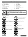
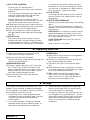
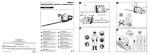
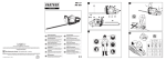
A EC Declaration of Conformity
: EU Overensstemmelseerklæring
The undersigned, authorised by E.O.P.I., declares that the following
product: B 522 M, manufactured by E.O.P.I., Valmadrera, Italia, are in
accordance with the European Directives 98/37/EEC (Machinery
Directive), 93/68/CEE (CE Marking Directive) & 89/336/CEE (Directive
on electromagnetic compatibility), directive 2000/14/CEE (Annex V).
Undertegnede, bemyndiget af E.O.P.I., erklærer herved, at følgende
produkter: B 522 M, E.O.P.I., Valmadrera, Italia, er i
overensstemmelse med de eurpæiske direktiver 98/37/EEC
(Maskineri direktiv), 93/68/CEE (CE mærkningsdirektiv) &
89/336/CEE (EMC-direktiv), direktiv 2000/14/CEE (Annex V).
DE
CE Konformitätserklärung
Der Unterzeichnete, bevollmächtigt durch E.O.P.I., erklärt, daß
folgende Geräte: B 522 M, hergestellt durch E.O.P.I., Valmadrera,
98/37/EEC
Italia,
den
Europäischen
Richtlinien
(Maschinenrichtlinie), 93/68/CEE (CE Kennzeichnungsrichtlinie) &
89/336/CEE (EMV Richtlinie) entsprechen, richtlinie 2000/14/CEE
(Anhang V).
FR
Déclaration de conformité Européenne
Le soussigné, dûment mandaté par E.O.P.I., déclare que le
produit suivant: B 522 M, fabriqués par E.O.P.I., Valmadrera,
Italia, est conforme aux Directives Européennes 98/37/EEC
(Directive Sécurité Machine), 93/68/CEE (Directive Marquage
CE) & 89/336/CEE (Directive EMC), directive 2000/14/CEE
(Annexe V).
F EG Conformiteitsverklaring
Ondergetekende, gemachtigd door E.O.P.I., verklaart dat de volgende
produkten: B 522 M, geproduceerd door E.O.P.I., Valmadrera, Italia
voldoen aan de Europese Richtlijnen 98/37/CEE (Machinerie Richtlijn),
93/68/CEE (EG Markering Richtlijn) & 89/336/CEE (Richtlijn aangaande
elektromagnetische compatibiliteit), richtlijn 2000/14/CEE (Annex V).
NO
EF Erklæring om Overensstemmelse
Undertegnede, autorisert av E.O.P.I., erklærer at f¯øgende produkt B
522 M, konstruert av E.O.P.I. 23868 Valmadrera (Lecco) Via Como,
72 Italia, er i overensstemmelse med føgende europeiske direktiver:
98/37/CEE (Maskineridirektiv), 93/68/CEE (CE-merkingsdirektiv) &
89/336/CEE (Direktiv om elektromagnetisk kompatibilitet), direktiv
2000/14/CEE (Annex V).
FI
EY Julistus Vastaavuudesta
Allekirjoittanut, E.O.P.I. in valtuttaamana, vakuuttaa että seuraavat
tuotteet: B 522 M, ja jotka on valmistanut E.O.P.I., Valmadrera, Italia,
ovat Euroopan direktiivien 98/37/EEC (Koneisto-direktiivi),
93/68/CEE
(CE
Merkintä-direktiivi)
&
89/336/CEE
(Elektromagneettinen Yhteensopivuus-direktiivi) mukainen, direktiivi
2000/14/CEE (Liite V).
SE
B 522 M
D
1
15
12
20
4
10
5
3
ES
16
11
Declaracion de cumplimiento de la directriz de la UE
El abajo firmante, autorizado por E.O.P.I., afirma que los siguientes
productos: B 522 M, fabricados por E.O.P.I., Valmadrera, Italia,
cumplen con las directivas Europeas 98/37/EEC (Directiva sobre
Maquinaria), 93/68/CEE (Directiva sobre Marcas de la CE) &
89/336/CEE (Directiva sobre ‘Compati-bilidad Electro Magnética’),
directiva 2000/14/CEE (Anexo V).
PT
IT
14
9
13
1 ltr
20 cm
17
18
6
17
7
19
Dichiarazione di Conformità CE
Il sottoscritto, autorizzato dalla E.O.P.I., dichiara che il seguente
prodotto: B 522 M, costruito da E.O.P.I., Valmadrera, Italia, é
conforme alle Direttive Europee: 98/37/EEC (Direttiva Macchine),
93/68/CEE (Direttiva Marcatura CEE) & 89/336/CEE (Direttiva
Compatibilità Elettromagnetica), direttiva 2000/14/CEE (Allegato V).
B1
B2
B3
B4
B5
B6
C1
C2
C3
C4
C5
E1
E2
E3
F1
F2
F3
Technikai leírások
Alulírott, rendelkezve a E.O.P.I. engedélyével, kijelenti, hogy a
jelentermék B 522 M, melyet a E.O.P.I. 23868 Valmadrera (Lecco) Via
Como, 72 Italia, gyártott, megfelel az európai szabványoknak:
98/37/CEE (gépekre vonatkozó), 93/68/CCE (márkázásnak) és
89/336/CEE
(elektromágneses
összeegyeztetehetöségnek)
megfelenek, direktíva 2000/14/CEE (Melléklet V).
@ ∆ήλωση Συµµρφωσης προς τις Eντολές της EE
O υπογεγραµµένος, µε eξουσιοδ&τηση της E.O.P.I., δηλώνει
&τι τα εξής προϊ&ντα: B 522 M, κατασκευασθέντα απ& την
E.O.P.I., Valmadrera, Italia, HΠA ανταποκρίνονται προς τις
Eυρωπαϊκές Eντολές 98/37/CEE (η περί Mηχανηµάτων
Eντολή), 93/68/CEE (η περί του Σήµατος CE Eντολή) &
89/336/CEE (η περί Hλεκτροµαγνητικής Συµβατ&τητας
Eντολή), Aηρεκτηβα 2000/14/CEE (Πρηπο επηε V).
INSTRUCTION MANUAL
GB
IMPORTANT INFORMATION: Please read these instructions
carefully and make sure you understand them before using
this unit. Retain these instructions for future reference.
BRUGERHÅNDBOG
DK
BETRIEBSANWEISUNG
DE
EG-försäkran om överensstämmelse
WICHTIGE INFORMATION: Lesen Sie diese Hinweise zur
Handha-bung des Geräts aufmerksam durch. Verwenden
Sie es erst, wenn Sie sicher sind, daß Sie alle
Anweisungen verstanden haben und gut aufbewahren.
Electrolux Outdoor Products
Via Como 72
23868 Valmadrera (Lecco)
ITALIA
Phone +39 0341 203111 - Fax +39 0341 581671
Our policy of continuous improvement means that the specification of products may be altered from time to time without prior notice.
Electrolux Outdoor Products manufacture products for a number of well known brands under various registered patents, designs and
trademarks in several countries.
© Electrolux Outdoor Products Italy
The Electrolux Group. The world’s No.1 choice.
FR
RENSEIGNEMENTS IMPORTANTS: Avant d’utiliser cet
appareil, veuillez lire atentivement les instructions et
assurez-vous de les avoir comprises. Conservez les
instructions pour référence ultérieure.
ES
BELANGRIJKE IMPORTANTS: Lees deze handleiding
aandachtig en zorg dat u ailes begrijpt alvorens de kettingzaag
te gebrulken en be-waar ze voor toekomstige raadpleging.
PT
FI
The Electrolux Group is the world’s largest producer of powered appliances for kitchen, cleaning and outdoor use. More than 55 million
Electrolux Group products (such as refrigerators, cookers, washing machines, vacuum cleaners, chain saws and lawn mowers) are
sold each year to a value of approx. USD 14 billion in more than 150 countries around the world.
VIKTIG INFORMASJON: Les disse anvisningene nøye
og forsikre deg om at du forstår dem før du bruker
enheten og oppbevar dem for sen-ere bruk.
INFORMAZIONI IMPORTANTI: Leggere le istruzioni
attentamente e capirle bene prima di usare il
prodotto. Conservare per ulteriore consultazione.
HASZNÁLATI ÚTMUTATÓ
HU
Jótállást vállalni csak rendeltetésszerüen használatba
vett gépekre tudunk. Kérj ü hogy a gép használatba
vétele elött gondosan olvassa el a kezelési utasításokat.
OHJEKIRJA
EΓXEIPI∆IO XEIPIΣMOE
TÄRKEÄÄ TIETOA: Lue nämä ohjeet huolellisesti ja
varmista, että olet ymmärtänyt ne, ennen kuin alat
käyttää tätä laitetta ja säilytä myöhempää tarvetta
varten.
ΣHMANTIKEΣ ΠΛHPOΦOPIEΣ: ∆ιαβάστε
πρoσεxτιxά αvτές τις οδηγίες xαι Φρovτίστε vα τις
xαταvoήσετε αvτ& τo µηχάvηµα xαι Φuλάξτε το για
vα το σuµβοuλεύεστε στο µέλλοv.
BRUKSANVISNING
SE
INFORMAÇÕES IMPORTANTES: Queira ler
cuidadosamente estas instruções e tenha certeza de
entendë--las antes de usar a serra e guarde para
consulta futura.
LIBRETTO D’ISTRUZIONI
IT
BRUKERHÅNDBOK
NO
INFORMACIÓN IMPORTANTE: Lea atentamente las
instrucciones y asegúrese de entenderlas antes de
utilizar esta aparato. Conserve las instrucciones para la
referencia en el futuro.
MANUAL DO OPERADOR
HANDLEIDING
NL
VIGTIGE OPLYSNINGER: Læs instruktionerne
omhyggeligt, før du bruger enheden og gemme til
senere henvisning.
MANUAL DE INSTRUCCIONES
MANUEL D’INSTRUCTIONS
Valmadrera, 15.12.01
Pino Todero (Direttore Tecnico)
E.O.P.I.
2% lit.
2%
Declaração de Conformidade
HU
1:50
50:1
2
O abaixo assinado, autorizado por E.O.P.I., declara que os seguintes
produtos: B 522 M, fabricada por E.O.P.I., Valmadrera, Italia. estão
de acordo com as Directivas Europeias 98/37/EEC Directiva de
Maquinaria), 93/68/CEE (Directiva de Marcação CE) e 89/336/CEE
(Directiva de Compatibilidade Electromagnética), directiva
2000/14/CEE (Apêndice V).
Undertecknad, auktoriserad av E.O.P.I., försäkrar att följande
produkter: B 522 M, tillverkade av E.O.P.I., Valmadrera, Italia, är i
överensstämmelse med följande europeiska direktiv 98/37/EEC
(Maskindirektiv), 93/68/CEE (CE-märknings-direktiv) & 89/336/CEE
(Elektromagnetisk kompatibilitet), direktiv 2000/14/CEE (Annex V).
PN 249072 REV. 02 (02/03)
8
A
VIKTIG INFORMATION: Läs instruktionerna noggrant och
försäkra dig om att du förstår dem innan du använder
utrustningen och spara dem för framtida behov.
GR
F4
F5
3
0,02
5
100
0,10
10
200
0,20
20
400
0,40
G
L1
L2
SUMMARY CHART TO IDENTIFY THE
CORRECT GUARD NEEDED, WITH DIFFERENT
CUTTING ATTACHMENTS
GB
DE
ÜBERSICHTSTABELLE ZUR AUSWAHL DES
RICHTIGEN SCHUTZBLECHES FÜR DIE
EINZELNEN SCHNEIDWERKZEUGE
DE
FR
TABLEAU RECAPITULATIF POUR LE
CORRECT ACCOUPLEMENT LAME OU TETE
FIL NYLON / DEFENSE DE SECURITE
FR
NL
OVERZICHTSTABEL OM TE BEPALEN WELKE
BESCHERMKAP GEBRUIKT MOET WORDEN
BIJ DE DIVERSE MAAI-ONDERDELEN
NL
NO
TABELL FOR KORREKT MONTERING AV
TRÅDSPOLE/SAGBLAD OG
SPRUTSKJÆRM/SIKKERHETSVÆRN
GB
52 cc
L3
1,18”
3 mm
L4
197”
5000mm
538242506
248960
4T
9”
230 mm
226134B
248960
H1
H2
H3
M1
M2
M3
4T
10”
255 mm
226135B
248960
8T
9”
M4
H4
M5
M6
8T
10”
255mm
M7
M8
TAULOKKO LEIKKAAVAN
PÄÄN/TURVASUOJUKSEN OIKEASTA
YHDISTELMÄSTÄ
FI
SE
SAMMANFATTANDE TABELL ÖVER KORREKT
KOMBINATION AV
SKÄRHUVUD/SÄKERHETSSKYDD
SE
DK
DK
OVERSIGTSTABEL VEDRØRENDE DEN
KORREKTE SAMMENSÆTNING AF KNIV OG
BESKYTTELSESSKÆRM
ES
ES
TABLA PARA EL CORRECTO ACOPLAMIENTO
DE LA CABEZA CORTANTE Y PROTECTOR DE
SEGURIDAD
PT
PT
TABELA DE RESUMO PARA A CORRETA
APLICAÇÃO DA CABEÇA CORTANTE E
DEFESA DE SEGURANÇA
IT
IT
TABELLA RIASSUNTIVA PER IL CORRETTO
ABBINAMENTO TESTA TAGLIENTE / DIFESA
DI SICUREZZA
HU
248960
H5
236713B
248960
M9
24T
9”
NO
FI
236711B
230mm
240998B
230mm
I
240936B
240553
N
236677
80T
9”
230mm
240953B
HU
ÖSSZEFOGLALÓ TÁBLÁZAT: A NYÍRÓFEJ
ÖSSZEÁLLITÁSA / BALESETVÉDELEM
GR
ΠEPIΛHΠTIKOΣ ΠINAKAΣ ΓIA THN
EΠIΣHMANΣH TOY KATAΛΛHΛOY
ΠPOΦYΛAKTHPA, ME ∆IAΦOPA KOΠTIKA
EΞAPTHMATA
240936B
240553
236677
Due to a constant product improvement programme, the factory
reserves the right to modify technical details mentioned in this
GR
manual without prior notice.
Im Sinne des Fortschritts behält sich der Hersteller das Recht
vor, technische Änderungen ohne vorherigen Hinweis
durchzuführen.
La Maison se réserve la possibilité de changer des
caractéristiques et des données de ce manuel à n’importe quel
moment et sans préavis.
Door konstante produkt ontwikkeling behoud de fabrikant zich
het recht voor om rechnische specificaties zoals vermeld in deze
handleiding te veranderen zonder biervan vooraf bericht te
geven.
Produsenten forbeholder seg all rett og mulighet til å forandre
tekniske detaljer i denne manualen uten forhåndsvarsel.
Jatkuvan tuotteen parannusohjelman tähden valmistaja pidättää
oikeuden vaihtaa ilman ennakkovaroitusta tässä ohjekirjasessa
mainittuja teknisiä yksityiskohtia.
Tilverkaren reserverar sig rätten att ändra fakta och uppgifter ur
handboken utan förvarning.
Producenten forbeholder sig ret til ændringer, hvad angår
karakteristika og data i nærværende instruktion, når som helst
og uden varsel.
La firma productora se reserva la posibilidad de cambiar las
características y datos del presente manual en cualquier
momento y sin previo aviso.
A casa productora se reserva a possibilidade de variar
características e dados do presente manual em qualquer
momento e sen aviso prévio.
La casa produttrice si riserva la possibilità di variare
caratteristiche e dati del presente manuale in qualunque
momento e senza preavviso.
A gyártó cég fenntartja a jogot arra, hogy a használati
utasitásban megadott adatokon és technikai tulajdonságokon
bármikor és elözetes bejelentés nélkül változtasson.
Λγω προγράµµατος συνεχούς βελτίωσης προϊντων, το
εργοστάσιο επιφυλάσσεται του δικαιώµατος να
τροποποιεί τις τεχνικές λεπτοµέρειες που αναφέρονται
στο εγχειρίδιο αυτ χωρίς προηγούµενη ειδοποίηση.
A. General description
1)
2)
3)
4)
5)
6)
7)
8)
9)
10)
ENGINE
SHAFT
THROTTLE TRIGGER
THROTTLE ADVANCE
RIGHT CONTROL HANDLE
BLADE
NYLON STRING HEAD
STOP SWITCH
CHOKE LEVER
STARTER HANDLE
11)
12)
13)
14)
15)
16)
17)
18)
19)
20)
HARNESS RING
SPARK PLUG
AIR FILTER
FUEL TANK CAP
MUFFLER SHIELD
ENGINE SHAFT JOINT
SAFETY GUARD
STRING HEAD SAFETY GUARD
LINE CUTTER BLADE
SAFETY GRIP
Safety precautions
If not used properly this Petrol Brushcutter can be dangerous.
The warnings and safety instructions must be followed to ensure reasonable safety and efficiency in using this product.The operator is responsible
for following the warnings and instructions in this manual and on the
product.
Explanation of Symbols
Warning
Read the user instructions carefully o make sure you understand all
the controls and what hey do.
Wear safety clothing:
Approved safety glasses or face
shield
Wear safety clothing:
Approved safety helmet
Wear safety clothing:
Approved ear defender
Wear safety clothing:
Approved gloves
Wear safety clothing:
Approved safety footwear
Do not smoke while refuelling or while operating the trimmer
Maximum blade speed
Do not use metal blades
MAX. 0000 Min-1
ENGLISH - 1
Blade thrust
Beware of projected objects
Maximum safety distance
Choke fully opened
(hot start / run)
Choke closed (cold start)
B. Safety precautions
1) Make sure all operators study this manual
carefully before using the trimmer; only use this
machine for usage specifically mentioned in
this manual.
Never allow children to use the trimmer.
2) When working with the trimmer wear suitable
clothes: a) Close fitting protective clothes ( do not
wear short trousers or loose clothes). b) Safety
shoes (do not wear sandals and do not work barefoot). c) Heavy-duty gloves. d) Safety face shield or
goggles. Ensure you peel off the protective films, if
existing, from the see - through plastic. e) Ear protection. f) Head protection when using circular saw
blades. Make sure you know how to stop the
engine in an emergency (see the section STARTING AND STOPPING ENGINE). Never use the
trimmer when tired, physically indisposed or under
the effect of alcohol, certain medicines or other
drugs. Be careful of the rotating cutting attachment
and hot surfaces on the unit.
3) Prolonged use of this product or other machines
exposing the operator to vibration may produce
Whitefinger’s disease (Raynaud’s Phenomenon).
This may reduce the hands’ ability to feel and regulate temperature and may produce general numbness. Continual or regular users should therefore
monitor closely the condition of their hands or fingers. If any of the symptoms appear, seek immediate medical advice. Always hold the trimmer firmly
with both hands. When working maintain a firm
foothold. The trimmer must be used exclusively as
recommended (see section SAFETY USAGE).
4) Do not carry the trimmer while the engine is
running even for short distances; switch off the
engine and carry the unit with the cutting head
behind you. When carrying the trimmer in a
vehicle, secure it to avoid fuel leakage. Always
empty the fuel tank before transporting the unit.
ENGLISH - 2
ATTENTION: For your safety the blade must be
kept at all times in its proper case during transport and storage.
Start the
trimmer on a flat surface. When starting the
unit, ensure you have a firm footing. Make sure
the blade or the nylon string head does not
touch the ground or any obstacle.
5) PRECAUTIONS AGAINST FIRE: do not operate
the trimmer near fire or spilled petrol. Do not
run the engine in closed or poorly ventilated
areas. EXHAUST GASES ARE POISONOUS
WHEN INHALED, THEY CAN CAUSE SUFFOCATION AND DEATH.
After refuelling always wipe off any spilled fuel.
Do not smoke during this operation. Start the
engine far away from the refuelling area and from
fuel containers (minimum distance 3 meters). Do
not refuel while the engine is still running.
6) Keep people and animals away from working area
(minimum distance 15 meters). If somebody
should approach you, turn the engine off and stop
the blade or the rotating head (see chapter
STARTING AND STOPPING THE ENGINE) as
during operation the blade or the nylon string
head might project grass, grit, or other debris. The
blade is sharp, be careful even if handling it when
the engine is off.
Wear heavy-duty gloves. Turn the engine off
and wait for rotating parts to stop completely
before working on the machine or before
touching the blade or the string head above all
to remove possible entangled material.
DO NOT USE THE MACHINE AT ALL IF THE
SPECIFIED SAFETY GUARD IS NOT FIRMLY
ATTACHED (see sections SAFETY USAGE and
BLADES AND NYLON STRING HEAD ASSEMBLY).
Pay careful attention to safety recommendations as you might put your life or somebody
else’s in danger as a result of: a) possible contact with cutting or rotating parts. b) possibility
of projection of various objects.
WARNING: do not start engine if it is not
attached to the shaft as the clutch might disintegrate. For units equipped with a clutch, be
sure the cutting attachment stops turning
when the engine idles.
C . Safety usage
This product must be held to the right of the
operator’s body.
This will ensure exhaust fumes are directed away
from the operator and will not be obstructed by
the operator’s clothing. If you have not used a
trimmer before, spend some time in becoming
familiar with the controls and method of usage
before operation.
Check the machine carefully before using it.
Make sure that there are no loosened screws,
damaged parts or fuel leakages.
Replace damaged or excessively worn accessories (blades, string heads, guards).
Ensure all maintenance or repair work is carried
out by an authorised service center.
N.B. In order to maintain performance and safety,
be sure to use original spare parts and accessories.
Avoid using the trimmer over excessively long
periods of time.
Excessive amounts of vibration can be harmful.
1) Remove from the working area grit, debris,
ropes, metal parts or any other object which
might get entangled around the rotating parts
or be dangerously projected.
Use only the correct accessory recommended
for the type of vegetation to be cut. Do not let
the rotating blade contact any foreign object
such as stones, rocks, cans etc.
Secure hair to keep it above shoulder height.
Before starting to work fit the harness. Adjust
harness with the buckle so that the trimmer is
well balanced on your right side and the blade
or string head is parallel to the ground. Always
maintain a firm foothold and a good balance
while using the machine. Do not move backwards while you work as obstacles may not be
visible.
The fitting of the safety pole barrier is obligatory on units equipped with a delta shaped handle when used with a metal blade.
The purpose of this safety pole barrier is to
maintain a safe distance between the metal
blade and the user under all normal or exceptional circumstances.
2) Harness ring (B) must never be moved from its
original position to avoid unbalancing the unit.
Front handles can be separately adjusted to
make usage easier on units fitted with “U”
shaped handles.
3) The following accessories can be assembled to
your trimmer: a) blade, b) nylon string head.
Do not attach any blade to a unit without proper installation of all required parts. Failure to
use the proper parts can cause the blade to fly
off and seriously injure the operator and/or
bystanders.
a) WHEN USING A BLADE ENSURE THE
CORRECT GUARD IS FITTED.
b) WHEN USING A NYLON STRING HEAD
ENSURE THE CORRECT GUARD IS FITTED.
When using the unit always hold the front part
of the machine (blade or nylon string head)
below your waist.
NYLON STRING HEAD:
Always make sure it has been correctly assembled and fitted.
The nylon head is suitable to cut grass and
weeds wherever there might be obstacles like
trees, fences or walls.
The nylon string head also reduces the likelihood of damaging small plants and trees bark.
Only use flexible, nonfilament nylon line in the
nylon line head as specified by the manufacturer. Never use metallic line which could break
off and become a dangerous projectile.
BLADE:
Always make sure it has been correctly fitted.
When fitting or changing a cutting device,
ensure you follow the instructions in the section
“Blade or nylon string head assembly” with
extreme precision. Fit these cutting devices
using all and only the parts as described, and
in the correct order.
4) BLADES: you can cut any type of grass,
brushwood or shrub.
Operate the machine like a sickle always cutting at full throttle.
5) WARNING: always use a well sharpened blade.
A blade with worn teeth besides providing poor
performance might also generate a sudden
thrust. This can result in a violent sideways kick
caused when the blade touches against wood
or solid bodies, such thrust might then cause
the operator to loose control of the machine
itself. Never attempt to work with a damaged
blade but replace it with a new one.
THRUST: can occur when using any type of circular blade within the risk area: therefore it is advisable to cut using the remaining area of the blade.
ENGLISH - 3
CIRCULAR SAW BLADE: it can be used to cut
sappling, small trees with a diameter up to 7
cm., to clean shrubs.
WARNING: IF A METAL 24-80 TOOTH BLADE
(A SAW TOOTH BLADE) IS USED A DOUBLE
SHOULDER HARNESS AND A SAFETY
GUARD (PROTECTION) MUST ALSO BE USED
AS MARKED IN THE SUMMARY CHART (SEE
CLOTHES SECTION IN SAFETY CHAPTER:
ALWAYS WEAR A HELMET).
ALWAYS USE GENUINE ACCESSORIES AND
SPARE PARTS AVAILABLE FROM AUTHORISED
SERVICING DEALERS.
THE USE OF NON-ORIGINAL ACCESSORIES
AND SPARE PARTS INCREASES THE RISK OF
ACCIDENTS AND IN SUCH A CASE THE
COMPANY IS NOT LIABLE FOR DAMAGE TO
PEOPLE AND/OR THINGS.
D. Fuel mix
Warning! The brushcutter “four stroke 52 PM ”
is equipped with a special 4 stroke engine with
waste lube , consequently it requires a totally sintetic 2 stroke engine oil or a McCulloch branded 2
stroke engine oil and unleaded petrol mix with a
minumum octane rating of 90 (see chart).
Warning! Do not use gasoline for any reasons,
as the engine will be seriously damaged.
IMPORTANT
Always shake the fuel mix container thoroughly
before pouring any fuel mix.
Fuel mix properties may deteriorate with time and
should be used up within 2 months.
We recommend that you prepare fuel mix according to your immediate requirements only. Never
use fuel mix more than 2 months old so as to
avoid possible engine damage.
WARNING
Do not smoke when re-fuelling.
Always open the fuel cap slowly, to release any
pressure build up in the tank.
Re-fuel in open spaces only, keeping away from
naked flames or sparks.
SAFE STORAGE OF FUEL
Petrol fuel mix is highly inflammable. Put out all
cigarettes, pipes and cigars before working with
fuel. Avoid spilling fuel.
Store fuel in a cool, well ventilated place, in an
approved container specifically designed for the
purpose. Never store engine with fuel in the tank in
enclosed, poorly ventilated areas, where fuel fumes
may reach an open flame, spark or pilot light such
as in a furnace, water heater, clothes dryer etc.
Petrol fumes can cause an explosion or a fire.
Never store large amounts of fuel.
To prevent possible restarting problems avoid
running the fuel tank dry. This also helps to
extend engine life.
E. Safety guard assembly
1) In the interest of safety, it is imperative that the
unit is used with the correct guard (P/N 247209)
when using any blade or a nylon string head,
except the 24-80 tooth blade. Line cutter blade
(L): assemble as illustrated.
2) When using a saw tooth blade (optional accessory), the correct guard must be fitted (P/N
240553).
A double shoulder harness must also be worn.
Only use blades or nylon string heads clearly
marked with a maximum speed of at least 10,500
min-1.
Follow the fitting instructions carefully.
N.B: Saw tooth blades (24 - 80 tooth) have a
central base diametre of 20mm and therefore
require the use of the appropriate size top flange
to ensure a correct fit. The part number is
detailed in the cutting attachment summary chart.
F. Blade and nylon string head assembly
Assemble the correct guard to suit the kind of
blade or nylon string head to be used (See section: SAFETY GUARD ASSEMBLY).
1) Assemble blade as illustrated:
a) Flange guard - b) Upper cap with blade
centering - c) Blade with text and directional
arrow facing upwards - d) Lower washer - e)
Fixed mower gauge - f) Blade locking screw
(length mm 16).
2) If you want to assemble the rotating mower
gauge,proceed as illustrated:
ENGLISH - 4
a) Flange guard - b) Upper cap with blade
centering - c) Blade with text and directional
arrow facing upwards - d) Lower washer - e)
Spacer - f) Rotating mower gauge - g) Blade
locking screw (length mm 34,5).
Replace the blade attachment bolt if damaged
in any way.
3) Make sure that the blade bore opening fits perfectly around the centering collar on the upper
cap.
Tighten counterclockwise.
While tightening, the blade assembly can be
held fast by inserting the wrench or the screwdriver supplied into the cap and gearcase holes.
To do this, rotate the cap intil the two holes
coincide.
4) Assemble nylon string head as illustrated:
a) Flange guard - b) Upper cap - c) Guard d)
Nylon string head
Tighten counterclockwise.
5) While tightening, the head assembly can be
held fast by inserting the wrench or the screwdriver supplied into the holes as already shown
for blade assembly.
WARNING: Do not use the guard for the nylon
string head (18) when using a metal blade.
G. Handle assembly
DOUBLE HANDLE
Adjust and secure double hand clamp by tightening the screws.
H. Starting and stopping the engine
WARNING: First read sections: SAFETY RULES,
SAFETY USAGE and SYMBOLS.
STARTING A COLD ENGINE
1) Position the on/off switch to the I (ON)
position, away from the «STOP» position.
2) Rotate the choke lever in the direction illustrated
by the arrows. This engages the fast idle system.
3) Squeeze the primer bulb (C) several times
until you see fuel begin to return back through
the tube (D) towards the fuel tank. Push the
decompression valve (B) down if your models
is fitted with one. Pull the starter handle until
the engine starts.
4) Hold the machine safely and allow the engine
to run for a few seconds. Grip the control handle firmly, pushing down on the safety trigger
(S) and then squeezing the accelerator trigger
(A). This action automatically releases the
spring loaded choke lever (E) disengaging the
fast idle system.
WARNING: The fast idle system does cause the
cutting attachment to rotate when engaged.
STARTING A WARM ENGINE
Position the on/off switch to the I (ON) position.
Squeeze the primer bulb (C) several times until
you see fuel begin to return back through tube
(D) to the fuel tank. Pull the starter handle until
the engine runs.
HOT ENGINE STARTING WITH
1) STOP switch on START position I. Trigger on
idle position (released).
Choke towards (open position ).
5) Depress the safety lever (S), squeeze the
accelerator trigger (A) and push the throttle
advance forwards (B). Now release the
accelerator trigger (A) and then the throttle
advance (B).
3) Press the primer bulb (C) several times until
you see fuel going back to carburetor through
pipe (D). Pull starter rope.
WARNING: when the throttle (B) advance is
engaged, the head or blade rotates.
5) ENGINE STOPPING
Press the stop switch moving it to STOP position 0.
WARNING: when the engine is switched off
rotating parts, blade or nylon string head, will
keep on rotating for a few seconds. Hold the
machine until all parts come to a standstill.
N.B. In an emergency the above mentioned
delay in stopping may be shortened by
touching blade parallel on the ground.
I. Carburettor adjustment
To adjust the idle speed, however, proceed as follows:
With engine running and warm, slowly turn screw
‘T’ clockwise until the engine runs smoothly with
a consistent noise level but without making the
cutting head rotate.
If the cutting attachment does move or the engine
runs too fast, slowly turn screw ‘T’ in an anticlockwise direction until the correct speed is obtained.
Precise numerical engine speed settings are mentioned in the technical detail chart in the front of
the owner’s manual.
L. Regular maintenance
From time to time ensure all screws are tight.
Replace damaged, worn, cracked or warped
blades. Always make sure nylon string head or
blade have been assembled correctly (see sections NYLON STRING HEAD and BLADE
ASSEMBLY) and blade fastener is tightened.
ENGLISH - 5
1) AIR FILTER CLEANING
(at least every 25 working hours).
A dust clogged air filter may cause carburetor
problems.
This may prevent the engine from reaching its
maximum speed and cause high fuel consumption and/or difficult starting.
Remove filter cover as shown in figure 1.
Carefully clean the inside of filter box. The filter
can also be cleaned with compressed air.
N.B. Slide the air filter back into its location (C) ensuring the tabs (A) are pointing downwards as illustrated,
ensure it clicks firmly into its airtight position.
2) Every 50 working hours inject the gearcase
with gear grease under high pressure through
hole (C).
3) SPARK PLUG
From time to time (at least every 50 hours)
remove and clean the spark plug and check
the electrode gap (0,5/0,6 mm.). Replace spark
plug about every 100 working hours or whenever
it is extremely encrusted. Heavily encrusted
electrodes can result from wrong fuel mixture
(too much oil in the petrol) or a poor quality of
oil in the fuel mix. Check and correct.
4) FUEL FILTER
To change fuel filter remove the tank cap and
pull out the filter with a piece of bent wire or
long forceps.
5) MOTOR MAINTENEANCE
Contact your Service Dealer every 100 working
hours.
This will reduce the possibility of unexpected
problems and will ensure maximum product life
and efficiency.
REGULARLY: it is important, in order to avoid
engine overheating, to remove dust and dirt
from slots, gaps and from in between cylinder
fins using a wooden scraper.
LONG STORAGE: empty fuel tank and run
engine until dry.
Store trimmer in a dry place.
M. Replacing nylon line
1) Loosen the locking nut on the base of the
nylon head by turning it clockwise.
2) Remove the base cover assembly.
Remove the empty spool from the housing and
discard any remaining line.
REWINDING NEW LINE
3) Prepare 2 lengths (8ft each) of 2.4 mm nylon
line. Thread 1 end of each line into the two
holes on opposite sides of the spool. Pinch the
exposed ends flat with a pair of pliers to prevent them slipping through the hole.
4) Wind the two lines in the same direction
around the spool.
REASSEMBLY
5) Slide the end of the two lines into the grooves
to hold the line temporarily.
6) Position the spool back into the housing and
pull the line through the eyelets.
7) Pull about 12cm (5ins) of line out on either
side.
8) Reassemble the nylon string head as illustrated; mower gauge,spring and locking nut (tighten in an anti-clockwise direction).
9) N.B: In order to extend the nylon line as it
wears down, pull the mower gauge downwards and turn it in a clockwise direction to
feed out the desired length of line.
N. Ecology
This chapter is about how to maintain the ” eco
features” of the machine as originally developed
by our engineers, the correct use of this machine
and handling of waste oil and fuel.
1. Research on the 4 stroke engine has been
developed in order to produce lower fuel consumption and low emission of polluting
exhaust gases
2. Use of the machinery: During the fuel filling
operation particular care should be taken to
avoid waste fuel polluting the enviroment.
ENGLISH - 6
3. When storing for a long period, empty fuel
tank and run engine until dry, observing the
same precautions as when filling.
4. Disposal of machines: Old machines can be
very dangerous for the environment - do not
throw them awway!! Please apply to the compotent body authorised to collect industrial
waste. As prescribed by National laws on
enviroment
Technical data
DISPLACEMENT (cm 3)
ENGINE OUTPUT (Kw) (ISO 8893)
BORE AND STROKE (mm)
ENGINE SPEED AT MAX POWER (min-1)
MAXIMUM SPEED, NO LOAD (min-1)
MINIMUM SPEED (min-1)
BLADE SHAFT SPEED (min-1)
BLADE LOCKING NUT TIGHTENING TORQUE (Nm)
DRY WEIGHT (kg)
FUEL TANK CAPACITY (cm 3)
Coil/flywheel magneto distance (mm)
VALVES GAUGE (mm)
SOUND PRESSURE LEVEL (AT THE OPERATOR’S EAR) dB(A) (EN 27917)
Measured sound power LEVEL LwAav (dBA) (ISO 10884)
GUARANTEED NOISE level LwAav (dBA) (ISO 10884)
VIBRATIONS LEVEL STRING HEAD (ISO 7916) (m/s2) MAX-MIN
VIBRATIONS LEVEL BLADE (ISO 7916) (m/s2) MAX-MIN
52
2
47x30
7.500
10.000
2.800
8.500
17
9,5
950
0,3
0,10/0,15
97
108
112
2.40 - 5.75
2.40 - 4.57
Fault finding table
runs badly
Engine will Engine
or looses power
not start
when cutting
Check STOP switch is in the position I.
Control fuel level min. 25%tank
capacity.
Check air filter is clean.
Remove spark plug, dry it, clean it
and adjust it, and replace it, if necessary.
Change fuel filter. Contact your dealer.
Carefully follow the cutting accessory assembly instructions.
Check metal cutting accessory is
sharp. Otherwise, contact your dealer.
•
•
•
•
The machine
runs but does
not cut well
•
•
•
•
•
•
Engine still gives trouble: contact your dealer.
ENGLISH - 7