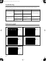
1
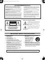
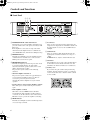
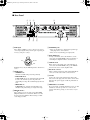
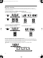
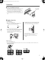
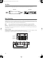
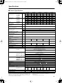
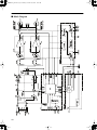
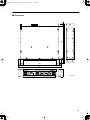
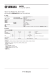
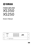
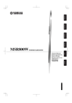
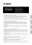
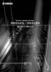
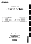
PC9501N_E.book Page 1 Monday, October 25, 2004 10:27 AM
POWER AMPLIFIER
Owner’s Manual
EN
PC9501N_E.book Page 6 Monday, October 25, 2004 10:27 AM
FCC INFORMATION (U.S.A.)
1. IMPORTANT NOTICE: DO NOT MODIFY THIS UNIT!
This product, when installed as indicated in the instructions contained in this manual, meets FCC requirements. Modifications not
expressly approved by Yamaha may void your authority, granted by
the FCC, to use the product.
2. IMPORTANT: When connecting this product to accessories and/
or another product use only high quality shielded cables. Cable/s
supplied with this product MUST be used. Follow all installation
instructions. Failure to follow instructions could void your FCC
authorization to use this product in the USA.
3. NOTE: This product has been tested and found to comply with the
requirements listed in FCC Regulations, Part 15 for Class “B” digital
devices. Compliance with these requirements provides a reasonable level of assurance that your use of this product in a residential
environment will not result in harmful interference with other electronic devices. This equipment generates/uses radio frequencies
and, if not installed and used according to the instructions found in
the users manual, may cause interference harmful to the operation
of other electronic devices. Compliance with FCC regulations does
not guarantee that interference will not occur in all installations. If
this product is found to be the source of interference, which can be
determined by turning the unit “OFF” and “ON”, please try to eliminate the problem by using one of the following measures:
Relocate either this product or the device that is being affected by
the interference.
Utilize power outlets that are on different branch (circuit breaker or
fuse) circuits or install AC line filter/s.
In the case of radio or TV interference, relocate/reorient the
antenna. If the antenna lead-in is 300 ohm ribbon lead, change the
lead-in to co-axial type cable.
If these corrective measures do not produce satisfactory results,
please contact the local retailer authorized to distribute this type of
product. If you can not locate the appropriate retailer, please contact Yamaha Corporation of America, Electronic Service Division,
6600 Orangethorpe Ave, Buena Park, CA90620
The above statements apply ONLY to those products distributed by
Yamaha Corporation of America or its subsidiaries.
* This applies only to products distributed by YAMAHA CORPORATION OF AMERICA.
(class B)
Explanation of Graphical Symbols
The lightning flash with arrowhead symbol within
an equilateral triangle is intended to alert the user to
the presence of uninsulated “dangerous voltage”
within the product’s enclosure that may be of
sufficient magnitude to constitute a risk of electric
shock to persons.
CAUTION
RISK OF ELECTRIC SHOCK
DO NOT OPEN
The exclamation point within an equilateral triangle
is intended to alert the user to the presence of
important operating and maintenance (servicing)
instructions in the literature accompanying the
product.
CAUTION: TO REDUCE THE RISK OF
ELECTRIC SHOCK, DO NOT REMOVE
COVER (OR BACK). NO USER-SERVICEABLE
PARTS INSIDE. REFER SERVICING TO
QUALIFIED SERVICE PERSONNEL.
The above warning is located on the top of the unit.
IMPORTANT SAFETY INSTRUCTIONS
1
2
3
4
5
6
7
8
9
10
Read these instructions.
Keep these instructions.
Heed all warnings.
Follow all instructions.
Do not use this apparatus near water.
Clean only with dry cloth.
Do not block any ventilation openings. Install in
accordance with the manufacturer’s instructions.
Do not install near any heat sources such as radiators, heat
registers, stoves, or other apparatus (including amplifiers)
that produce heat.
Do not defeat the safety purpose of the polarized or
grounding-type plug. A polarized plug has two blades with
one wider than the other. A grounding type plug has two
blades and a third grounding prong. The wide blade or the
third prong are provided for your safety. If the provided plug
does not fit into your outlet, consult an electrician for
replacement of the obsolete outlet.
Protect the power cord from being walked on or pinched
particularly at plugs, convenience receptacles, and the
point where they exit from the apparatus.
11
12
13
14
Only use attachments/accessories specified by the
manufacturer.
Use only with the cart, stand, tripod,
bracket, or table specified by the
manufacturer, or sold with the
apparatus. When a cart is used, use
caution when moving the cart/
apparatus combination to avoid
injury from tip-over.
Unplug this apparatus during
lightning storms or when unused for long periods of time.
Refer all servicing to qualified service personnel. Servicing
is required when the apparatus has been damaged in any
way, such as power-supply cord or plug is damaged, liquid
has been spilled or objects have fallen into the apparatus,
the apparatus has been exposed to rain or moisture, does
not operate normally, or has been dropped.
WARNING
TO REDUCE THE RISK OF FIRE OR ELECTRIC SHOCK, DO NOT EXPOSE THIS APPARATUS TO RAIN OR MOISTURE.
(98-6500)
PC9501N_E.book Page 1 Monday, October 25, 2004 10:27 AM
PRECAUTIONS
PLEASE READ CAREFULLY BEFORE PROCEEDING
* Please keep this manual in a safe place for future reference.
WARNING
Always follow the basic precautions listed below to avoid the possibility of serious injury or even death from electrical
shock, short-circuiting, damages, fire or other hazards. These precautions include, but are not limited to, the following:
Power supply/Power cord
Water warning
• Only use the voltage specified as correct for the device. The required voltage is
printed on the name plate of the device.
• Do not expose the device to rain, use it near water or in damp or wet conditions,
or place containers on it containing liquids which might spill into any openings.
• Use only the included power cord.
• Never insert or remove an electric plug with wet hands.
• Do not place the power cord near heat sources such as heaters or radiators, and
do not excessively bend or otherwise damage the cord, place heavy objects on
it, or place it in a position where anyone could walk on, trip over, or roll anything
over it.
Do not open
• Do not open the device or attempt to disassemble the internal parts or modify
them in any way. The device contains no user-serviceable parts. If it should
appear to be malfunctioning, discontinue use immediately and have it inspected
by qualified Yamaha service personnel.
If you notice any abnormality
• If the power cord or plug becomes frayed or damaged, or if there is a sudden
loss of sound during use of the device, or if any unusual smells or smoke
should appear to be caused by it, immediately turn off the power switch,
disconnect the electric plug from the outlet, and have the device inspected by
qualified Yamaha service personnel.
• If this device should be dropped or damaged, immediately turn off the power
switch, disconnect the electric plug from the outlet, and have the device
inspected by qualified Yamaha service personnel.
CAUTION
Always follow the basic precautions listed below to avoid the possibility of physical injury to you or others, or damage
to the device or other property. These precautions include, but are not limited to, the following:
Power supply/Power cord
• Do not place the device in an unstable position where it might accidentally fall
over.
• Remove the electric plug from the outlet when the device is not to be used for
extended periods of time, or during electrical storms.
• Do not block the vents. This device has ventilation holes at the front and rear to
prevent the internal temperature from becoming too high. In particular, do not
place the device on its side or upside down. Inadequate ventilation can result in
overheating, possibly causing damage to the device(s), or even fire.
• When removing the electric plug from the device or an outlet, always hold the
plug itself and not the cord. Pulling by the cord can damage it.
• Do not use the device in the vicinity of a TV, radio, stereo equipment, mobile
phone, or other electric devices. Doing so may result in noise, both in the device
itself and in the TV or radio next to it.
Location
• Before moving the device, remove all connected cables.
• If several of the devices are mounted in an EIA-compliant rack, carefully read the
section “Rack Mounting” on page 10.
• Do not use the device in a confined, poorly-ventilated location. If this device is
to be used in a small space other than an EIA-standard rack, make sure that
there is adequate space between the device and surrounding walls or other
devices: at least 5cm at the sides, 10cm behind and 10cm above. Inadequate
ventilation can result in overheating, possibly causing damage to the device(s),
or even fire.
• Do not expose the device to excessive dust or vibrations, or extreme cold or heat
(such as in direct sunlight, near a heater, or in a car during the day) to prevent
the possibility of panel disfiguration or damage to the internal components.
(5)-2
1/2
PC9501N_E.book Page 2 Monday, October 25, 2004 10:27 AM
Connections
Handling caution
• Before connecting the device to other devices, turn off the power for all devices.
Before turning the power on or off for all devices, set all volume levels to
minimum.
• When turning on the AC power in your audio system, always turn on the device
LAST, to avoid speaker damage. When turning the power off, the device should
be turned off FIRST for the same reason.
• Use only speaker cables for connecting speakers to the speaker jacks. Use of
other types of cables may result in fire.
• Do not insert your fingers or hands in any gaps or openings on the device
(vents, etc.).
• Be sure to connect to a properly grounded power source. A ground screw is
provided on the rear panel of this device for maximum safety and shock
prevention. If the mains outlet is not grounded, be sure to connect the ground
screw to a confirmed ground point before plugging the device into the mains.
Improper grounding can result in electrical shock.
• Avoid inserting or dropping foreign objects (paper, plastic, metal, etc.) into any
gaps or openings on the device (vents, etc.) If this happens, turn off the power
immediately and unplug the power cord from the AC outlet. Then have the
device inspected by qualified Yamaha service personnel.
• Do not use the device for a long period of time at a high or uncomfortable
volume level, since this can cause permanent hearing loss. If you experience
any hearing loss or ringing in the ears, consult a physician.
• Do not rest your weight on the device or place heavy objects on it, and avoid use
excessive force on the buttons, switches or connectors.
• Do not use this device for any purpose other than driving loudspeakers.
Use only Neutrik NL4FC plugs for connecting Speakon connectors.
Yamaha cannot be held responsible for damage caused by improper use or modifications to the device.
Always turn the power off when the device is not in use.
The performance of components with moving contacts, such as switches, volume controls, and connectors, deteriorates over time. Consult qualifi ed Yamaha service
personnel about replacing defective components.
Illustrations in this manual are for explanatory purposes only, and may not match the actual appearance of the product during operation.
Company names and product names used in this Owner’s Manual are trademarks or registered trademarks of their respective owners.
(5)-2
2/2
PC9501N_E.book Page 5 Monday, October 25, 2004 10:27 AM
Introduction
Thank you for purchasing a Yamaha PC9501N, PC6501N, PC4801N, PC3301N, or PC2001N Series Power
Amplifier.
The PC Series of power amplifiers was developed from Yamaha’s wealth of experience in building PA
equipment and its tradition of careful attention to every detail of circuit design. These power amplifiers feature
high power and superb quality together with superior reliability and stability, guaranteeing the highest
possible audio performance.
Main features include
• Three modes are provided to support a broad range of applications: STEREO mode which can be driven by
two independent sources, PARALLEL mode in which a monaural source drives both channels, and BRIDGE
mode in which the two internal amps function as a single mono amp.
• Balanced XLR connector and Euroblock connector inputs, and Speakon connector and five-way binding
post outputs are provided.
• A high pass filter switch that cuts frequencies below 20 Hz, and detented attenuators and level meters for
channels A and B are provided.
• Metering and indicators include easily visible two-channel level meters, a PROTECTION indicator that
shows the state of various protection systems (power on/off detection, output protection, DC detection), a
TEMP indicator that indicates heat sink overheating, and a REMOTE indicator that indicates the external
remote status.
• Variable-speed low-noise fans ensure high reliability.
• The PC3301N enables parallel connection of multiple high-impedance speakers that support 100 V line
output.
• An optional external amp control unit, such as the ACU-16C, enables you to monitor or control the amplifier
via a network. For the latest information about amp control units, please visit our website:
http://www.yamahaproaudio.com/
This Owner’s Manual applies to the PC9501N, PC6501N, PC4801N, PC3301N, and PC2001N power
amplifier. In order to take full advantage of your power amplifier and enjoy long and trouble-free operation,
please read this Owner’s Manual carefully before using your Power Amplifier.
Contents
Introduction ............................................................ 5
Controls and Functions .........................................
Front Panel..........................................................
Rear Panel ..........................................................
Speaker connections...........................................
6
6
7
8
Connection ............................................................. 9
Using a Euroblock connector .............................. 9
Speaker Connection............................................ 9
Air Flow ................................................................. 10
Rack Mounting ..................................................... 10
Specifications.......................................................
General Specifications ......................................
Block Diagram...................................................
Dimensions .......................................................
11
11
12
13
Troubleshooting ................................................... 14
Performance graph .............................................. 14
5
PC9501N_E.book Page 6 Monday, October 25, 2004 10:27 AM
Controls and Functions
■ Front Panel
234
7
1
5
1 POWER/STAND-BY switch and indicator
This turns the power of the amplifier on/off. When you
press the switch to turn on the power, the indicator will
light green.
If the amplifier is connected to an amp control unit
ACU16-C and the amplifier has been commanded to
enter STAND-BY mode, this indicator will light orange.
2 REMOTE indicator
This indicator will light green if the amplifier is being
controlled from an external device connected to the
DATA port located on the rear panel.
3 PROTECTION indicator
This indicator lights up red when the protection circuit
is operating. During this time, the amp will be
disconnected from the speaker system, and no sound
will be output from the speaker.
The protection system activates in the following
situations:
• When the amplifier is turned on
The protection system activates for approximately ten
seconds when the amplifier is turned on. After ten
seconds, the protection system deactivates
automatically and the amplifier is ready for normal
operation.
• If a DC voltage is detected at the amplifier’s outputs
Turn off the power, and then turn the power back on
again.
• If the amplifier overheats
When this occurs, the TEMP indicator will be lit.
You should turn off the amplifier and allow it time to
cool down. See the Precautions section of this Owner’s
Manual for ways to prevent the amplifier overheating.
4 TEMP indicator
This indicator will light red if the heat sink temperature
exceeds 85 degrees Celsius.
6
6
8
7
5 Level meters
These are nine-segment level meters that indicate the
output level of output jacks A and B. If the distortion of
the output signal exceeds 1%, the red CLIP indicator
will light.
6 Volume knobs
These are detented volume knobs that attenuate the
input signals of channels A and B over a range of –∞
– 0 dB.
In BRIDGE mode, only the channel A knob is used.
7 Air intakes
The amplifier has a forced-air cooling fan that takes in
air from the front and exhausts it from the rear. You
must make sure that these intakes are not obstructed.
8 Security cover
If you want to keep the volume settings from being
modified, attach the included security cover using the
screw holes shown below, so that the volume controls
are inaccessible.
PC9501N_E.book Page 7 Monday, October 25, 2004 10:27 AM
■ Rear Panel
1 2
3
4
20
5
6
8
7
1 XLR inputs
9
4 SPEAKERS jacks
These balanced XLR-3-31 type connectors are used to
connect input signals. They are wired pin 1–ground, pin
2–hot (+), and pin 3–cold (–).
• These are Speakon type output jacks. Speakon type
cable plugs can be connected here.
• These are five-way binding post output jacks.
5 DATA PORT jack
Hot
1
2
Ground
3
An amp control unit, such as the ACU16-C, can be
connected to the DATA PORT jack for monitoring or
controlling the amplifier from the external device.
6 AMP ID switch
Cold
In Bridge mode, only the XLR input of the channel A is
active.
2 MODE switch
• STEREO mode
Channels A and B will operate independently.
• PARALLEL mode
In PARALLEL mode, the channel A input signal will
be sent to the channel A power amp and to the
channel B power amp. The channel B input jack is not
used.
• BRIDGE mode
In BRIDGE mode, channels A and B will operate
simultaneously, functioning as a single mono amp.
3 HPF 20 switches
When an amp control unit, such as the ACU16-C, is
connected to the DATA PORT jack 5, the AMP ID
switch can be used to set the amplifier’s ID.
7 Euroblock connector
This is a balanced input jack. The included Euroblock
connector can be used to make connections here.
8 AC inlet
Connect the socket of the included AC cable to this
inlet. Connect the plug of the AC cable to an AC outlet
that meets the power supply conditions printed below
this inlet.
9 GROUND Screw terminal
If you are having a problem with hum or noise, use this
terminal to connect to ground or to connect to the
chassis of the mixer, preamp, or other device in your
system.
These switches are used to turn on and off the HPF
(High Pass Filter) for each channel. When set to ON,
frequencies below 20 Hz are filtered using a 12 dB/
octave high pass filter.
7
PC9501N_E.book Page 8 Monday, October 25, 2004 10:27 AM
■ Speaker connections
Speakers can be connected to the amplifier as shown below. Note that speaker impedance will vary according to the
connection method and the number of speakers. Please be sure that your speaker’s impedance is not less than the relevant
minimum value indicated below.
Connection configurations for STEREO and PARALLEL modes
When using 5-way binding post output jacks
When using the Speakon connector
or
–
+
Minimum speaker
impedance: 4 Ω
+
–
Minimum speaker
impedance: 4 Ω
Minimum speaker
impedance: 4 Ω
Minimum speaker
impedance: 4 Ω
Connection configurations for BRIDGE mode
When using 5-way binding post output jacks
–
When using the Speakon connector
+
Minimum speaker
impedance: 8 Ω
Minimum speaker
impedance: 8 Ω
When connecting high-impedance speakers in parallel (PC3301N only)
The number of speakers that can be connected varies depending on the rated input of the speakers. The PC3301N can be
connected to speakers with a total rated input of up to 625 W. For example, if you connect five speakers with a rated input of
5 W (25 W), thirty speakers with a rated input of 10 W (300 W) and twenty speakers with a rated input of 15 W (300 W), the
amplifier can be used with a total rated speaker input of 625 W as shown below:
CAUTION Be sure to use speakers that support the PC3301N’s line-out voltage of 100 V.
1
5W
5
5W
1
10W
30
10W
1
15W
20
15W
5 W x 5 speakers (25 W) 10 W x 30 speakers (300 W) 15 W x 20 speakers (300 W)
Total rated input of speakers: 625 W (maximum)
8
PC9501N_E.book Page 9 Monday, October 25, 2004 10:27 AM
Connection
■ Using a Euroblock connector
Use a screwdriver
to fix the wires.
1. If the wire insertion ports are closed, turn the screws on top
of the connector counterclockwise to open the ports.
2. Insert the wires into the appropriate ports, following the
indication of the pole on the input terminal, turn the screws
on top of the connector clockwise to fix the wires.
3. Attach the Euroblock connector to the input terminal on the
unit.
+
–
G
■ Speaker Connection
5-way binding post
1. Turn off the POWER switch.
2. Remove the cover attachment screws and remove the
protective cover from the speaker terminals.
Be sure that the bare wire ends do not jut out from the
terminals and touch the chassis. The following shows
how the cable should look when correctly attached.
Chassis
Bare wire
Screw
3. Remove about 15 mm of insulation from the end of each
speaker cable, and pass the bare wire through the holes
in the appropriate speaker terminals. Tighten the
terminals to securely clamp the wires. Refer to page 8
for speaker polarities.
15mm*
Note to users in the USA:
Please use Class 3 wiring. (PC9501N, PC6501N, PC4801N)
Please use Class 2 wiring. (PC3301N, PC2001N)
4. Reattach the protective cover over the speaker
terminals.
Speaker
cable
* Actual size
Speakon connector
1. Turn off the POWER switch.
2. Insert the Neutrik NL4FC plugs into the Speakon connector on the rear of the amplifier, and turn clockwise to lock.
Neutrik NL4FC plugs
CHANNEL A
STEREO or PARALLEL
CHANNEL B
BRIDGE
Neutrik
Amplifier
Neutrik
Amplifier
Neutrik
Amplifier
1+
1–
2+
2–
A+
A–
B+
B–
1+
1–
2+
2–
+
1+
1–
B+
B–
–
9
PC9501N_E.book Page 10 Monday, October 25, 2004 10:27 AM
Air Flow
This unit uses a forced cooling system in which air comes in through the front opening and goes out the rear.
Side View
Rear View
Front
Air intake
Air exhaust
Rack Mounting
If multiple high-power amp units are mounted in a rack with poor ventilation, the heat from the amps will cause the interior
of the amp to become very hot, causing the performance of the amps to be impaired. In particular, when mounting in a rack
whose back can not be left open, mount according to the following instructions.
Rack:
Fan:
Mounting:
Leave a gap of 10 cm or more between the rear panel of the rack and the rear panel of the amplifier.
Use a fan with 1.5 m3/min or more maximum wind and 5 mmH2O or more maximum static pressure.
Install the fan kit on the top slot or the top panel of the rack and install a blanking panel between two amps.
If the unit is rack mounted and transported frequently, we recommend that the rear of the unit be supported by fitting a pair
of metal brackets, one each side.
Example of mounting
The top figure shows an example of a fan kit (panels and two fans) on the top slot of the rack. The fans are Minebea 3115PS12T-B30 (with 0.9 m3/min maximum wind and 5 mmH2O maximum static pressure).
The bottom figure is a dimensional diagram of a panel on which two 3115PS-12T-B30 are installed.
Fan kit
PC9501N/PC6501N/
PC4801N/PC3301N/
PC2001N
76.2
78
ø4
4-
71.5±0.1
5
248
.
-6
x
88
.5
5
78
4C1
71.5±0.1
PC9501N/PC6501N/
PC4801N/PC3301N/
PC2001N
11
4
463
480
10
Unit: mm
PC9501N_E.book Page 11 Monday, October 25, 2004 10:27 AM
Specifications
■ General Specifications
PC9501N
Output Power
1 kHz, THD+N= 1%
120V(US)/
240V(A)
8 Ω/STEREO
MIN
4 Ω/STEREO
20 Hz–20 kHz
THD+N= 0.1%
PC6501N
PC4801N
PC3301N
230V(EU)
120V(US)/
240V(A)
230V(EU)
1000 W x 2 1050 W x 2
700 W x 2
750 W x 2
550 W x 2
500 W x 2
1600 W x 2 1650 W x 2 1100 W x 2 1150 W x 2
850 W x 2
800 W x 2
120V(US)/
240V(A)
230V(EU)
120V(US)/
240V(A)
PC2001N
230V(EU)
120V(US)/
240V(A)
230V(EU)
350 W x 2
400 W x 2
230 W x 2
250 W x 2
600 W x 2
700 W x 2
400 W x 2
450 W x 2
8 Ω/BRIDGE
3200 W
3300 W
2200 W
2300 W
1700 W
1600 W
1200 W
1400 W
800 W
900 W
8 Ω/STEREO
925 W x 2
950 W x 2
650 W x 2
650 W x 2
475 W x 2
450 W x 2
330 W x 2
350 W x 2
200 W x 2
230 W x 2
1400 W x 2 1500 W x 2
4 Ω/STEREO
8 Ω/BRIDGE
MIN
16 Ω/BRIDGE(100V)
1 kHz
2 Ω/STEREO
20ms nonclip
4 Ω/BRIDGE
Power Bandwidth
MIN
930 W x 2
930 W x 2
725 W x 2
700 W x 2
525 W x 2
550 W x 2
325 W x 2
400 W x 2
2800 W
3000 W
1860 W
1860 W
1450 W
1400 W
1050 W
1100 W
650 W
800 W
–
–
–
–
–
–
625 W
625 W
–
–
800 W x 2
900 W x 2
500 W x 2
600 W x 2
1600 W
1800 W
1000 W
1200 W
2300 W x 2 2300 W x 2 1500 W x 2 1600 W x 2 1200 W x 2 1200 W x 2
4600 W
4600 W
3000 W
3200 W
2400 W
2400 W
MIN
10 Hz–40 kHz (THD+N= 0.5%)
MAX
0.1%
Frequency Response
MAX
0 dB
RL= 8 Ω, Po= 1 W
TYP
0 dB
f=20 Hz–50 kHz
MIN
–1 dB
MAX
0.1%
MIN
70 dB
MAX
–70 dB
Half Power
Total Harmonic Distortion (THD + N)
20 Hz–20 kHz, Half Power
Intermodulation distortion (IMD)
60 Hz:7 kHz, 4:1, Half Power
Channel Separation
Half Power, RL= 8 Ω, 1 kHz, Vol. max.,
input 600 Ω shunt
Residual Noise
Vol. min., 20 Hz–20 kHz (DIN AUDIO)
SN Ratio
20 Hz–20 kHz (DIN AUDIO)
Damping Factor
MIN
106 dB
105 dB
103 dB
MIN
RL=8 Ω, f= 1 kHz
Sensitivity
(Vol. max.) Rated Power into 8 Ω
TYP
101 dB
800
9 dB
8 dB
500
6 dB
4.5 dB
Voltage Gain (Vol. max.)
TYP
32 dB
Maximum Input Voltage
MIN
22 dB
TYP
20 kΩ/Balanced, 10 kΩ/Unbalanced
Input Impedance
Controls
Connectors
Front Panel
POWER switch (ON/OFF)
Two 31-step Volume knobs (one per ch)
Rear Panel
MODE switch (STEREO/BRIDGE/PARALLEL)
HPF switch (ON/OFF) fc=20 Hz 12 dB/octave
DIP switch (6P)
Input
SPEAKON/ch, 5-way binding posts
Network
RJ45 x 2
Power
AC inlet
POWER/STAND-BY
Green/Orange
PROTECTION
Red
TEMP
Red (heatsink temp
REMOTE
10 points LED meter/ch
Load protection
POWER switch ON muting, DC detection
Amp. Protection
Comp. : THD
Cooling
1Ω)
0.5%
Dual Variable-speed fan
Idling
Output power, 4 Ω
55 W
750 W
(US)/1000
W(A)
40 W
1100 W
Dimensions (W x H x D)
Included accessories
90 ˚C), VI limiter (RL
Temp. detection (heatsink temp
Limiter
Weight
85 ˚C)
Green
Level Meters
Power Consumption
3 dB
XLR–3–31 type/ch
Euroblock connector/ch
Output
Indicators
100 dB
700 W
(US)/800
W(A)
800 W
450 W
(US)/600
W(A)
600 W
450 W
(US)/500
W(A)
500 W
350 W
480 x 88 x 456 mm
13 kg
12.5 kg
Power cord, Security cover, Owner’s Manual, 3-pin Euroblock connector x 2
0 dB=0.775 Vrms, Half Power=1/2 Output Power (3 dB below rated power)
Specifications and descriptions in this owner’s manual are for information purposes only.
Yamaha Corp. reserves the right to change or modify products or specifications at any time
without prior notice. Since specifications, equipment or options may not be the same in
every locale, please check with your Yamaha dealer.
European models
Purchaser/User Information specified in EN55103-1 and EN55103-2.
Inrush Current: 31A
Conforms to Environments: E1, E2, E3 and E4
11
PC9501N_E.book Page 12 Monday, October 25, 2004 10:27 AM
■ Block Diagram
12
PC9501N_E.book Page 13 Monday, October 25, 2004 10:27 AM
46
4
380
456
26
■ Dimensions
370
30 25
480
88
25 30
Unit: mm
13
PC9501N_E.book Page 14 Monday, October 25, 2004 10:27 AM
Troubleshooting
The following table lists the main causes of abnormal operation and the corrective measures required as well as the
protective circuit operation in each case.
Indicator
Possible Cause
CLIP indicator lights up
PROTECTION indicator lights
up
Remedy
Protection Circuit
There is a short at the
amplifier’s speaker outputs, the
speaker’s inputs, or in the
wiring.
Locate and remove the short.
The impedance of the connected
speaker is too low.
Use a speaker with a minimum
impedance of 4Ω (8Ω in Bridge
mode).
The heat sink temperature has
exceeded 90°C.
Check the ventilation around the
amplifier and improve the
airflow if necessary.
The thermal protection circuit
activates to protect the power
transistors.
A DC voltage of ±2 V or greater
was detected in the amplifier’s
output circuit.
Consult your dealer or a Yamaha
service center.
The output relay activates to
protect the speaker system.
The PC limiter circuit activates
to protect the power transistors.
Performance graph
PC6501N
Mode:STEREO
Both ch
1000
Power
Consumption[W]
100
10
1
1
10
100
1000
10000
Output
Power[W]
PC4801N
Power consumption[W]
Power
Consumption[W]
100
10
Output
Power[W]
1
10
100
1000
PC2001N
Power consumption[W]
10000
Mode:STEREO
Both ch
Power
Consumption[W]
1000
100
10
1
1
1000
Power
Consumption[W]
100
10
1
10
100
1000
10000
Output
Power[W]
PC3301N
1000
1
Mode:STEREO
Both ch
1
Mode:STEREO
Both ch
10000
14
10000
10
100
1000
Output
Power[W]
10000
Power consumption[W]
Power consumption[W]
10000
Power consumption[W]
PC9501N
Mode:STEREO
Both ch
Power
Consumption[W]
1000
100
10
1
1
10
100
1000
Output
Power[W]
PC9501N_E.book Page 6 Monday, October 25, 2004 10:27 AM
IMPORTANT NOTICE FOR THE UNITED KINGDOM
Connecting the Plug and Cord
WARNING: THIS APPARATUS MUST BE EARTHED
IMPORTANT. The wires in this mains lead are coloured in accordance
with the following code:
GREEN-AND-YELLOW : EARTH
BLUE
: NEUTRAL
BROWN
: LIVE
As the colours of the wires in the mains lead of this apparatus may not
correspond with the coloured markings identifying the terminals in
your plug proceed as follows:
The wire which is coloured GREEN-and-YELLOW must be connected
to the terminal in the plug which is marked by the letter E or by the
safety earth symbol
or colored GREEN or GREEN-and-YELLOW.
The wire which is coloured BLUE must be connected to the terminal
which is marked with the letter N or coloured BLACK.
The wire which is coloured BROWN must be connected to the terminal which is marked with the letter L or coloured RED.
• This applies only to products distributed by Yamaha-Kemble Music (U.K.) Ltd.
(3 wires)
This mark indicates a dangerous electrically live terminal.
When connecting an external wire to this terminal, it is necessary
either to have “a person who have received appropriate
guidance on handling” make the connection or to use leads or a
cord that have been manufactured in such a way that the
connection can be made simply and without problem.
PC9501N_E.book Page 1 Monday, October 25, 2004 10:27 AM
For details of products, please contact your nearest Yamaha
representative or the authorized distributor listed below.
Pour plus de détails sur les produits, veuillez-vous adresser à Yamaha ou
au distributeur le plus proche de vous figurant dans la liste suivante.
NORTH AMERICA
CANADA
Yamaha Canada Music Ltd.
135 Milner Avenue, Scarborough, Ontario,
M1S 3R1, Canada
Tel: 416-298-1311
Die Einzelheiten zu Produkten sind bei Ihrer unten aufgeführten
Niederlassung und bei Yamaha Vertragshändlern in den jeweiligen
Bestimmungsländern erhältlich.
Para detalles sobre productos, contacte su tienda Yamaha más cercana
o el distribuidor autorizado que se lista debajo.
Yamaha Music Central Europe GmbH,
Branch Belgium
Rue de Geneve (Genevastraat) 10, 1140 - Brussels,
Belgium
Tel: 02-726 6032
FRANCE
U.S.A.
Yamaha Corporation of America
6600 Orangethorpe Ave., Buena Park, Calif. 90620,
U.S.A.
Tel: 714-522-9011
CENTRAL & SOUTH AMERICA
MEXICO
Yamaha de México S.A. de C.V.
Calz. Javier Rojo Gómez #1149,
Col. Guadalupe del Moral
C.P. 09300, México, D.F., México
Tel: 55-5804-0600
BRAZIL
Yamaha Musical do Brasil Ltda.
Av. Reboucas 2636-Pinheiros CEP: 05402-400
Sao Paulo-SP. Brasil
Tel: 011-3085-1377
ARGENTINA
Yamaha Music Latin America, S.A.
Sucursal de Argentina
Viamonte 1145 Piso2-B 1053,
Buenos Aires, Argentina
Tel: 1-4371-7021
PANAMA AND OTHER LATIN
AMERICAN COUNTRIES/
CARIBBEAN COUNTRIES
Yamaha Music Latin America, S.A.
Torre Banco General, Piso 7, Urbanización Marbella,
Calle 47 y Aquilino de la Guardia,
Ciudad de Panamá, Panamá
Tel: +507-269-5311
EUROPE
Yamaha Musique France
BP 70-77312 Marne-la-Vallée Cedex 2, France
Tel: 01-64-61-4000
ITALY
Yamaha Musica Italia S.P.A.
Combo Division
Viale Italia 88, 20020 Lainate (Milano), Italy
Tel: 02-935-771
SPAIN/PORTUGAL
Yamaha-Hazen Música, S.A.
Ctra. de la Coruna km. 17, 200, 28230
Las Rozas (Madrid), Spain
Tel: 91-639-8888
SWEDEN
Yamaha Scandinavia AB
J. A. Wettergrens Gata 1
Box 30053
S-400 43 Göteborg, Sweden
Tel: 031 89 34 00
GERMANY
Yamaha Music Central Europe GmbH
Siemensstraße 22-34, 25462 Rellingen, Germany
Tel: 04101-3030
SWITZERLAND/LIECHTENSTEIN
Yamaha Music Central Europe GmbH,
Branch Switzerland
Seefeldstrasse 94, 8008 Zürich, Switzerland
Tel: 01-383 3990
AUSTRIA
Yamaha Music Central Europe GmbH,
Branch Austria
Schleiergasse 20, A-1100 Wien, Austria
Tel: 01-60203900
INDONESIA
PT. Yamaha Music Indonesia (Distributor)
PT. Nusantik
Gedung Yamaha Music Center, Jalan Jend. Gatot
Subroto Kav. 4, Jakarta 12930, Indonesia
Tel: 21-520-2577
KOREA
Yamaha Music Korea Ltd.
Tong-Yang Securities Bldg. 16F 23-8 Yoido-dong,
Youngdungpo-ku, Seoul, Korea
Tel: 02-3770-0660
MALAYSIA
Yamaha Music Malaysia, Sdn., Bhd.
Lot 8, Jalan Perbandaran, 47301 Kelana Jaya,
Petaling Jaya, Selangor, Malaysia
Tel: 3-78030900
TAIWAN
Yamaha KHS Music Co., Ltd.
3F, #6, Sec.2, Nan Jing E. Rd. Taipei.
Taiwan 104, R.O.C.
Tel: 02-2511-8688
NORWAY
Norsk filial av Yamaha Scandinavia AB
Grini Næringspark 1
N-1345 Østerås, Norway
Tel: 67 16 77 70
OTHER EUROPEAN COUNTRIES
Yamaha Music Central Europe GmbH
Siemensstraße 22-34, 25462 Rellingen, Germany
Tel: +49-4101-3030
AFRICA
Yamaha Corporation,
Asia-Pacific Music Marketing Group
Nakazawa-cho 10-1, Hamamatsu, Japan 430-8650
Tel: +81-53-460-2313
MIDDLE EAST
TURKEY/CYPRUS
Yamaha Music Central Europe GmbH
Siemensstraße 22-34, 25462 Rellingen, Germany
Tel: 04101-3030
Yamaha Music Gulf FZE
LB21-128 Jebel Ali Freezone
P.O.Box 17328, Dubai, U.A.E.
Tel: +971-4-881-5868
Yamaha Music & Electronics (China) Co.,Ltd.
25/F., United Plaza, 1468 Nanjing Road (West),
Jingan, Shanghai, China
Tel: 021-6247-2211
Yamaha Music Asia Pte., Ltd.
#03-11 A-Z Building
140 Paya Lebor Road, Singapore 409015
Tel: 747-4374
YS Copenhagen Liaison Office
Generatorvej 6A
DK-2730 Herlev, Denmark
Tel: 44 92 49 00
OTHER COUNTRIES
THE PEOPLE’S REPUBLIC OF CHINA
SINGAPORE
DENMARK
THE UNITED KINGDOM
Yamaha-Kemble Music (U.K.) Ltd.
Sherbourne Drive, Tilbrook, Milton Keynes,
MK7 8BL, England
Tel: 01908-366700
ASIA
BELGIUM/LUXEMBOURG
THAILAND
Siam Music Yamaha Co., Ltd.
891/1 Siam Motors Building, 15-16 floor
Rama 1 road, Wangmai, Pathumwan
Bangkok 10330, Thailand
Tel: 02-215-2626
OTHER ASIAN COUNTRIES
Yamaha Corporation,
Asia-Pacific Music Marketing Group
Nakazawa-cho 10-1, Hamamatsu, Japan 430-8650
Tel: +81-53-460-2317
OCEANIA
AUSTRALIA
Yamaha Music Australia Pty. Ltd.
Level 1, 99 Queensbridge Street, Southbank,
Victoria 3006, Australia
Tel: 3-9693-5111
COUNTRIES AND TRUST
TERRITORIES IN PACIFIC OCEAN
Yamaha Corporation,
Asia-Pacific Music Marketing Group
Nakazawa-cho 10-1, Hamamatsu, Japan 430-8650
Tel: +81-53-460-2313
THE NETHERLANDS
Yamaha Music Central Europe,
Branch Nederland
Clarissenhof 5-b, 4133 AB Vianen, The Netherlands
Tel: 0347-358 040
HEAD OFFICE Yamaha Corporation, Pro Audio & Digital Musical Instrument Division
Nakazawa-cho 10-1, Hamamatsu, Japan 430-8650
Tel: +81-53-460-2441
PA11
Yamaha Pro Audio global web site
http://www.yamahaproaudio.com/
Yamaha Manual Library
http://www2.yamaha.co.jp/manual/english/
This Document is printed on recycled chlorine free (ECF) paper with soy ink.
U.R.G., Pro Audio & Digital Musical Instrument Division, Yamaha Corporation
© 2004 Yamaha Corporation
WD61630 411APAP8.2-01A0
Printed in Japan