1
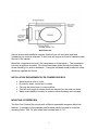
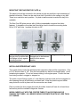
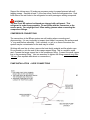
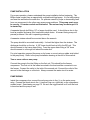
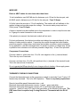
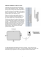
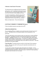
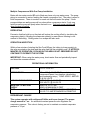
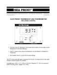
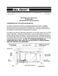
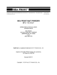
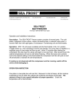
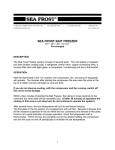
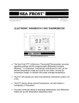
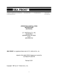
148 OLD CONCORD TURNPIKE BARRINGTON, NH 03825 USA
TEL (603) 868-5720
FAX (603) 868-1040
E-Mail:[email protected]
1-800-435-6708
www.seafrost.com
SEA FROST BDxpx A/W
12 OR 24 VOLT
WITH AEO
AIR AND WATER COOLED SYSTEM
Description
The BDxpx is a pre-charged refrigeration/freezer system with component parts. Reseal
able quick connect fittings are used to make leak tight connections between the plates
and the remote compressor. These connectors may be disconnected without loosing
refrigerant. The refrigerant used in the BDxpx is R-404a. R-404a has special handling
requirements. It is a blend of three refrigerants and is a high-pressure refrigerant with
good low temperature characteristics. The system uses a Danfoss BD 150 compressor.
It is a permanent magnet brushless DC motor, hermetically sealed. The refrigerant is
cooled by both air and water. Direct evaporator cold plates made of stainless steel and
copper coils are cooled by the refrigerant and keep at the desired temperature by a
thermostat cycling the compressor.
CONDENSING UNIT LOCATION AND MOUNTING
The water-cooling option should be considered supplemental cooling. Installation
should proceed with a proper air-cooled installation first. The water-cooling feature
should be used to enhance efficiency on occasions when cold-water temperatures are
encountered or interior cabin air temperatures are extreme.
The design of the Sea Frost BDxpx compressor box allows placement in an enclosed
space such as a cabin locker or sail locker. Intake air should be drawn in from the cabin
area to insure the coolest, driest air supply. Standard 4" duct hose may be used.
Discharge will need to be vented to allow warm air to escape. The fan may be unscrewed and turned over to reverse airflow.
Avoid intake ducting from the exterior of the boat this will cause damp salt air to be
drawn in increasing corrosion. This will also increase below deck moisture.
ALLOW 1.5" CLEARANCE BETWEEN THE CONDENSER (BACK VENT AREA) AND
ANY BULKHEAD TO INSURE PROPER AIRFLOW THROUGH THE CONDENSER.
1
Service access and installation requires that the front, left end (inlet) and back
(condenser) air outlet be exposed. A duct hose will require 4 inches of clearance past
the end of the cabinet.
Mount the compressor box level, (the compressor is at the bottom). The compressor
box may be platform mounted. Two holes have been drilled through the bottom for
screw mounting to a shelf or bulkhead. If using the bulkhead mount bracket kit, follow
directions supplied with the kit.
INSTALLATION REQUIREMENTS FOR COMPRESSOR BOX
•
•
•
•
•
Never block air inlet or outlet.
Provide for driest, coolest air for intake.
Fan may be turned over to reverse airflow.
Total air duct length for intake should not exceed four feet and one bend.
Make sure installation location is vented to allow discharge air to escape.
MOUNTING A FREEZER BIN
The Sea Frost Freezer Bin mounts with a Wellnut expandable neoprene blind hole
fastener. A template or the stainless steel brackets should be used to locate the
mounting holes. Drill 1/4" pilot holes then increase them to 1/2".
2
MOUNTING THE EVAPORATOR PLATE (s)
The plate(s) should be mounted in the cabinet as high as possible to take advantage of
thermal convection. Plates can be used as a shelf, mounted on the ceiling or any wall.
There is no restriction as to position. If a plate is wall mounted a vertical ice tray kit is
available.
The Sea Frost BD plate mounts with a Wellnut expandable neoprene blind hole
fastener. A template or the plate itself should be used to locate the mounting holes.
Drill a 3/16" pilot hole. Increase this hole to 3/8".
1. Place Well-nut insert all
the way into Pre-drilled hole
until flange is firmly against
mounting surface.
2. Pass Machine screw
through part to be fastened
and the white spacer
washer.
3. Tighten until snug.
INSTALLING REFRIGERANT LINES
Two copper lines connect the stainless steel evaporator plate and the compressor. One
is 5/16" and the other is 1/8". Run the lines behind any and all serviceable parts. Avoid
heated engine spaces. Do not coil excess tubing in an engine space. Protect the lines
from being crushed, snagged or stepped on.
The quick connect fittings require a 1 inch diameter clearance hole and are staggered to
allow passing through a bulkhead or insulated wall. Keep the plastic cap and shrink
wrap protective cover in place until the connections are made.
Plan to insulate the lines copper lines with Armorflex closed cell foam for at least three
feet as they exit the insulated refrigerator /freezer.
WORK CAREFULLY WITH THE COPPER TUBES TO AVOID PINCHING OR
KINKING THE TUBES. ALL BENDS SHOULD BE SMOOTH WITH NO LESS THAN
A 2" RADIUS.
3
Support the tubing every 18 inches as necessary using tie wraps fastened with selftapping screws. Insulate at least 3' of the line set as it exits the refrigerator box. Seal
both sides of the exit holes in the refrigerator box with permagum sealing compound.
WARNING:
The Sea Frost BD system is shipped pre-charged with refrigerant. This
refrigerant is under some pressure. Do not fiddle with the connectors or the
service ports. You might get hurt! Wear safety glasses when connecting the
compressor fittings.
COMPRESSOR CONNECTIONS
The connections in the BDxpx system are self-sealing when connecting and
disconnecting. It is very important to inspect (and clean if necessary) the surfaces and
"o" ring seals before assembly. If dirt, moisture, or grit, is on these connectors the
system may be contaminated or the seal may be ruined.
Working with one line at a time, remove the heat shrink material and the plastic caps.
Do not scratch or nick the end of the orange-capped fitting. This is a metal-to-metal
seal. Connect the larger copper line to the compressor fitting. Connect the small copper
line to the remaining fitting. Use two wrenches to tighten the fittings wrench snug then
1/8 turn. (See separate data sheet on connections.)
PUMP INSTALLATION ~ HOSE CONNECTIONS
M
4
PUMP INSTALLATION
For proper operation, please understand the pump installation before beginning. The
BDxpx water-cooled uses a magnetically coupled centrifugal pump. It is not self-priming
and must be well below the water line. Air pockets caused by loops or descending lines
from one component to the other may cause pump problems. This pump must never
be run dry. It is water cooled and lubricated. The wet end may be destroyed if it
is started dry.
A separate through hull fitting 1/2" or larger should be used. It should be as low in the
boat as possible and away from head and cockpit drains. A forward facing scoop will
prevent problems if the unit is operating underway.
A seawater strainer should be mounted above the seacock.
The pump should be mounted horizontally. It should be higher than the strainer. The
discharge should be on the top. A 3/8” hose should feed up hill to the BD unit. This
should connect to the lower water fitting. From the upper water fitting a 3/8” hose
should connect to a through hull above the water line.
For quiet operation suspend the pump on its hoses or mount using a rubber strip bolted
to the pump body. Refer to the pump installation drawing at the end of this manual.
Two or more units on one pump
Connect the pump to the inlet fitting on the first unit. This should be the freezer
compressor. The first unit is the lowest mounted in the boat and the connected to run
the freezer. Connect the outlet to the inlet of the second unit. Connect the outlet of the
second to the discharge or a third etc. Always connect the water circuit in series.
PUMP WIRING
Inside the compressor box connect the red pump wire to the (+) on the water pump
relay. Connect the black wire to the (-) terminal (top row, right side) on the compressor
module board. See drawing on page 12. Be sure the toggle switch is off until the boat
is launched and the pump is wet.
5
WIRE SIZE
Refer to ABYC tables for wire sizes other than these:
12-volt installations use AWG #8 wire for distances up to 10 feet for the wire pair, and
#6 AWG wire for distances up to 25 feet for the wire pair. Fuse 30 Amps.
24 Volts, halve the wire size of 12-volt installation. The module will self calibrate to the
applied voltage and provide proper fan voltage. The remote water pump must be a
24volt pump. Fuse 15 Amps.
A buss or terminal may be installed next to the compressor in order to drop the wire size
to 10 gauge for easier connection to the module.
If the polarity is reversed, the electronic module will not work.
For best performance, the electronic module must always be connected directly to the
battery or battery selector switch. Connecting the module through the boat's breaker
panel may cause a voltage drop; small wires and multiple connectors create resistance.
In any application, use the next largest wire if in doubt, to prevent a voltage drop. A fuse
is preferred over a breaker as it has less potential voltage drop. A fuse is not provided.
Compressor Connections
Connect a black or yellow wire from 12 or 24 volts negative to the (-) terminal board.
This is the top row of terminals.
Connect a red wire from 12 or 24 volts positive to the (+) terminal of the terminal board.
This is the second row of terminals.
Do not operate the BDxpx directly from a charger without a battery. Never apply power
to any of the other terminals.
THERMOSTAT WIRING CONNECTIONS
Connect the thermostat wires at the compressor module to terminals C and T using 1/4"
female crimp terminals. This is for AEO operation. There is no polarity requirement.
Remote (snowflake panel) thermostat wires ~ red.
Electronic thermostat thermometer (version 1) wires ~ green and white
Electronic thermostat thermometer (version 2 & 3) cat 5 data cable with RJ 45
connector. Install a 3-amp ATC fuse in the fuse holder on the Module PCB board. The
PBC board fuse is required only if using Electronic Thermostat with the RJ-45
jack.
6
REMOTE THERMOSTAT INSTALLATION
Install the panel-mounted thermostat within 50
inches of the refrigerator/ freezer. The capillary
sensing tube must enter the cabinet and reach to
the side or bottom of the cold plate or the second
plate in a two-plate hook up. The second plate is
the plate without the expansion valve.
Make sure the thermostat capillary does not
contact any tubing as it enters the cabinet. Pull
all excess capillary into the insulated cabinet.
Slide the bulb clip onto the edge of the plate and
over the sensing bulb as shown in the drawing to
the right. The sensing bulb must be in excellent
thermal contact with the plate. We recommend
that the probe be mounted on the plate in one of
the lower mounting positions as shown in the
drawing below. This is best because these
positions remain colder.
The SEA FROST BD (Snowflake) thermostat is variable. Turning the knob fully
counterclockwise turns the unit "OFF". The fully clockwise setting is the coldest. The
thermostat may be adjusted to obtain any temperature desired in the cabinet.
7
Calibration of the Remote Thermostat
The thermostat may be calibrated should the warmest
setting be too cold. To calibrate the thermostat remove
the mounting screws and tip the panel forward. About
an inch into the case is a black adjustment screw.
To lower box temperature, rotate this screw counter
clockwise. One full revolution will change the box
temperature approximately 6 degrees F. To raise the
temperature in the box rotate the screw clockwise.
Make small adjustments. Record all adjustments.
ELECTRONIC THERMOSTAT THERMOMETER (Option)
Follow the detailed instructions provided with the ETT.
OPERATION DESCRIPTION
Once installed the BDxpx is started by turning the thermostat clockwise from the off
position. The BDxpx will run until the plate reaches the set temperature of the
thermostat.
Turning the thermostat counter clockwise lowers the temperature at which the BDxpx
will switch off. The BDxpx will remain off until the plate temperature rises about 10
degrees F. The BDxpx is either on or off. It will not cool faster with a colder setting.
The SEA FROST BDxpx is a small system. It is efficient in its electrical conversion of
energy to heat movement. By being small, it is quiet, compact, has low electrical
starting requirements and running power draw, and is able to be air-cooled. It will take
some time to cool a warm cabinet.
Pump Operation: The water pump has a switch on the left end of the compressor
cabinet. With the pump switch on the pump will operated automatically when the
compressor starts.
You may want to switch off the pump when leaving the boat unattended. This is
especially important when jellyfish, seaweed and other trash is present in the water and
could block the intake sea strainer. Be sure the pump is switched off when operating
the system when the boat is out of the water.
8
Multiple Compressors With One-Pump Installation
Boats with two water-cooled BD units fitted may have only one water pump. The pump
piping is connected in series, feeding the freezer compressor first. The pump is wired to
both compressors. There is a switch on each unit that will control the pump. If both
pump switches are on the pump will run when either compressor starts. If only one
switch is on the pump will pump when that unit is on. Turn both pump switches off
when the boat is hauled.
DEFROSTING
Excessive frost/ice build up on the plate will reduce the cooling effect by insulating the
evaporator plate(s). Allowing the evaporator plate(s) to warm above freezing is one
method of defrosting. Boiling water or a scraper will also work.
OPERATION INSPECTION
Within a few minutes of starting the Sea Frost BDxpx, the tubing in close proximity to
the valve mounted on the plate and the valve itself will be noticeably cold. IF AFTER 20
MINUTES OF OPERATION, COOLING IN THIS AREA IS NOT OBSERVED DO NOT
CONTINUE TO OPERATE THE SYSTEM.
IMPORTANT: When using the water pump, check water flow and periodically inspect
and clean the seawater strainer.
OPERATIONAL INFORMATION
VOLTAGE
12 D.C. or 24 D.C.
AMP/HR DRAW
4.3 to 17.8 @ 12 VOLTS (Dependant upon
compressor speed, low pressure valve setting,
and condensing temp.) PUMP ADDS 1 AMP/HR
.5 @ 24 VOLTS
10.4 VOLTS @ 12 VOLTS
22.8 VOLTS @ 24 VOLTS
AWG # 8 TO 10 FEET
AWG # 6 MAXIMUM 25 FEET
12 VOLT 30 AMP STANDARD AUTOMOTIVE
24 VOLT 15 AMP STANDARD AUTOMOTIVE
LOW VOLTAGE CUT OFF
WIRE SIZE TO BATTERY
SUPPLY
FUSE:
REFRIGERANT CHARGE
This system operates with refrigerant R-404a and is pre charged. The proper
charge amount is 7 oz. An automatic/constant pressure valve regulates the
evaporator pressure. This valve is factory pre-set to maintain a constant evaporator
pressure of 15 psi.
9
Do not remove the plastic moisture cap on the expansion valve or turn the knob
beneath it.
WARNING! Do not use refrigerant with any additives, including but not limited to:
oil, dye, and leak stop.
The BDxpx is intended to operate only with the cover in place. This insures airflow
through the air condenser.
Charge amount will not affect the evaporator pressure (low side pressure). If
adjustment is needed be sure to reinstall the plastic moisture cap immediately.
High pressure operating pressures for both air and air/water cooling are charted.
Allow 10% error.
BDxpx OPERATING PRESSURE
404A REFRIGERANT
400
350
Pressure PSI
300
250
BDxpx Air
BDxpx A/W
200
150
100
50
0
40 45 50 55 60 65 70 75 80 85 90 95
BDxpx Air
10 10 11 11 12
0 5 0 5 0
111 120 129 140 150 161 173 187 200 213 229 245 260 279 297 315 336
BDxpx A/W 101 110 120 129 140 151 163 176 190 203 218
Temperature Degrees F
10
WATER COOLED MAINTENANCE
Drain all water from the pump, sea strainer, hoses and water coil in the BD housing
when entering a freezing climate. Switch off the pump to avoid dry pump operation.
TROUBLESHOOTING
A light emitting diode (LED) is connected between terminals (fan +) and D. In case the
electronic unit records an operational error, the diode will flash a number of times. The
number of flashes depends on what kind of operational error was recorded. Each flash
lasts 1/4 second. After the actual number of flashes there will be a delay with no
flashes, the sequence for each error recording is repeated every 4 seconds. Flashes
will only occur in the fault mode with the system on.
See additional trouble shooting information available at www.seafrost.com
OPERATIONAL ERRORS SHOWN BY LED
Number of
flashes
5
4
3
2
1
Error type
Thermal cut-out of electronic unit (If the refrigeration system
has been too heavily loaded, or if the ambient temperature is high,
the electronic unit will run too hot).
Minimum motor speed error (If the refrigeration system is too
heavily loaded, the motor cannot maintain minimum speed 1,850
rpm).
Motor start error
A. (The system might be overcharged.) Has charge been added?
B. Faulty module.
C. This fault may also occur when the compressor is trying to start
a warm system or on initial start up on a new system. Several
attempts and then start up can be normal.
Do not let out refrigerant until first contacting Seafrost!
Fan over-current cut-out (The fan is defective).
Battery protection cut-out (The voltage is outside the cut-out
setting. Low voltage.)
Operation of the fan or fan and pump with no faults and no cooling at the expansion
valve indicates that the compressor has no refrigerant. Amp draw will be lower than
normal running amps but should be above 5 amps. If this condition exists a leak has
developed that will require fixing. Refrigerant will have to be added to restore operation.
Switch off the unit until repairs can be made.
11
WIRING
NOTE: When using the modular thermostat connection (#13) there are no connections
on thermostat terminals (#11).
1. Electronic unit
2. Battery
3. Fuse
4. Main switch (optional)
5. LED for operational errors
6. Fan
7. Pump
8. Fuse 7 amp
9. Pump Switch
10. Relay
11. Thermostat
12. R1- Resister for pre-setting speed
(optional) or Jumper for AEO module
13. 3 amp Fuse & RJ45 jack for optional
Electronic Thermostat.
12
13
14
Our Repair Policy
Your Sea Frost BD system is manufactured to the highest standards and thoroughly
tested. If you experience problems with your system requiring technical service, return
it to us freight prepaid.
When a system is returned to us we will fix manufacturing defects and failures occurring
in normal operation for one year from the date of purchase or from the date of first
usage/commissioning at no charge, and return it to you freight prepaid (surface freight)
anywhere in the continental United States. Installation damage and damage to the
electrical parts will be favorably considered however this damage is not our
responsibility.
Improper wiring, improper voltage, corrosion, and water damage are not considered
manufacturing defects. It is your job to install and maintain your system in a reasonable
manner to prevent possible problems.
Proper installation and reasonable care will give you many years of excellent operation.
Please notify us before returning your system for repair.
SEA FROST
148 OLD CONCORD TURNPIKE
BARRINGTON, NH 03825
(800) 435-6708 (603) 868-5720
15