1
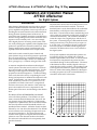
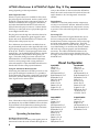
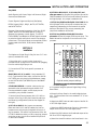
Copyright 1998 by SMART Devices Inc.
5945 Peachtree Corners East
Norcross, GA 30071-1337
Table of Contents
SECTION
SECTION
SECTION
SECTION
SECTION
1
2
3
5
6
AFT660 AFTERBURNER
INTRODUCTION
..........................
INSTALLATION ....................................
OPERATING INSTRUCTIONS
.......
HOOK-UP DIAGRAMS
.................
SCHEMATICS ....................................
2
3
4
5
10
AFT660PnP AFTERBURNER W/ DIGITAL PLUG 'N PLAY
SECTION 7
INTRODUCTION
.......................... 14
SECTION 8
INSTALLATION .................................... 15
SECTION 9
OPERATING INSTRUCTIONS
....... 17
SECTION 10
SCHEMATICS ................................... 18
SMART products are designed to deliver unsurpassed quality in workmanship and performance. The
following information gives detailed instructions on the installation and operation of the SMART AFT660
processor. We strongly encourage new owners of the AFT660 to thoroughly read this entire manual before placing their new SMART product into service. This will ensure that the AFT660 will be operated
properly to give the superior performance that it was designed to deliver.
For service or installation assistance, please call our
Technical Support Department between the hours of
8 a.m-5 p.m. E.S.T., Mon.-Fri.
1-800-45-SMART
LIMITED WARRANTY: SMART products and accessories are warranted against malfunction or failure due to defects in workmanship or materials for a period of one year from the date of shipment. If a problem occurs during the
warranty period, the unit will be repaired, or replaced at our option, without charge for materials or labor. If air freight
is requested by the dealer, the difference between air and surface charges will be billed to the dealer. This limited
warranty does not cover products that have been abused, altered, modified, or operated in other than specified conditions. Prior factory approval is required on all returns. Returned equipment or defective parts must be shipped
freight prepaid to us by the dealer or customer.
Our limited warranty does not cover damages resulting from accident, misuse or abuse, lack of responsible care, or
failures not attributable to manufacturing defects, except as provided herein. SMART Devices, Inc. makes no warranties, express or implied, including warranties of merchantability or fitness for a particular purpose.
RETURN POLICY: Factory authorization MUST be obtained before returning any product. A 15% restocking charge
will be issued on unused equipment (in original box) that is returned for credit. Credit is issued to the dealers account. The credit may be used against future purchases and no cash transactions are offered. All returns must be
shipped freight prepaid by the dealer. Equipment returned without a factory RA (Return Authorization) will be refused.
AFT660 Afterburner & AFT660PnP Digital Plug 'N Play
Installation and Operation Manual
AFT660 Afterburner
For Digital Systems
Introduction
Many theatres added digital sound in order to present
the best available format, but found that their present
power amplifiers and speakers were not up to the job of
handling the increased sound levels without distortion
during the most dynamic portions of the movie. Increased dynamic capability means the sound difference
between average dialog levels and the maximum action
sequence can be extremely wide. You cannot simply
add a digital player to an existing sound system without closely studying the capability of the amplifiers and
speakers to reproduce the increased sound levels. Most
existing cinema stereo systems were designed to adequately handle the maximum levels of optical stereo.
With louder sounds created by more channels and
more dynamic range, more sound pressure is produced.
This can cause annoying “sound bleed through” to adjacent auditoriums through common air conditioning
ducts, passageways, a common ceiling and thin walls.
A common complaint from audiences about digital
sound systems is that the sound is too loud. Our hearing is most sensitive to mid-range frequencies. Louder
mid-range sounds appear to be sharp or piercing in
proportion to the bass frequencies. A skilled recording
artist can fix this in the mix by re-equalizing the track
during loud sequences to minimize the subjective harsh
sound. Unfortunately, you cannot control the content
of the soundtrack you receive. An operator who is responsible for 12 booths cannot run to a single booth
and turn it down every few minutes. Often, what happens is the sound level is set to compensate for the
loudest parts of the movie and the dialog is then hard to
hear.
The Model AFT660 AFTERBURNER from SMART
solves all of these problems. The AFT660 is an automatic 6-channel threshold limiter that “burns off” the
top dynamic range of the soundtrack. Unlike simple
compressors or peak limiters, this circuit does not affect
the sound dynamics until the threshold (which is adjustable) has been reached. All louder sounds are then
reduced by a 2:1 ratio above the threshold. The AFT660
is extra sensitive to the mid-range frequencies that our
ears are most sensitive to. The stage and surround
channels track together to keep the channels balanced
whenever one of the channels reaches its threshold.
The subwoofer’s threshold level is set separately from
the other channels.
2
The chart below shows how the sound pressure is controlled when the threshold is reached. The actual
threshold point is set by the installer in the auditorium.
Some theatres would require a lower threshold level
than others. The end result is that a normal dialog level
can be achieved consistently and the loud passages are
controlled automatically. The AFT660 is installed between the output of any digital player and the rest of
the system. Convenient plug in cables make the installation quick and easy. The product only occupies 1 3/
4” of rack space. An emergency bypass switch on the
front of the product will hard wire the digital player
around the AFT660 so that it won’t cause a failure to
the digital system.
If the system amplifiers and auditorium speakers are
not quite big enough, the AFT660 will control the
amount of power that is fed to them. A reduced sound
level means less complaints from patrons and less
sound bleed through to other auditoriums. The action
of the limiters has been carefully shaped so that you
cannot hear the product working. The resulting sound
would appear to be similar to a good optical SR print.
However, all the other sterling attributes of the digital
recording are preserved, such as extended fidelity, no
soundtrack noise and low distortion.
INSTALLATION AND OPERATION
A large button on the front of the product allows the operator to select the mode of operation. If the digital
soundtrack you receive is well recorded and well balanced, then do nothing. The signals will pass through
the AFT660 without being altered. However, if you receive a screamer, the operator can push the ENABLE
button and the automatic level control kicks in. No special training of the staff is required.
Installation
Inputs and Outputs
The output of the digital decorder should feed directly
into the input of the AFT660 for the unit to operate
properly. However, if desired, the AFT660 can be installed after the processor so that the AFT660 can monitor the levels of both optical and digital prints using the
Afterburner Breakout board (Part #0660A390). See the
Afterburner Breakout board section of the Setting the
Threshold Levels instructions.
See section 5 for configuration diagrams for various
types of systems.
If the AFT660 is installed into an existing digital sound
system, it will not effect any calibration settings that
were made previously. Only the threshold levels of the
AFT660 need to be adjusted.
The AFT660 has two inputs, both of which are connected together in parallel. One input is a female DB25
connector, and the other is a header pin connector.
Both will accept the outputs of any six channel digital
decoder. Only one input will be used and the choice
will depend on the other equipment used (see hookup
diagrams). Smart offers adapter cables to mate any
digital decoder to the AFT660. See the illustrations at
the end of the manual for specific hookup instructions.
The AFT660 has two outputs, both of which are connected together in parallel. One output is a male DB25
connector, and the other is a header pin connector.
Only one output will be used. The output from the
AFT660 will mate with the rest of the sound system. On
SMART processors, this will be the digital inputs on the
processor. See the illustrations at the end of the manual
for specific hookup instructions.
Setting The Threshold Levels
There are two threshold levels on the AFT660 that need
to be set after hooking the unit into the sound system.
One is the threshold level for the five main channels
(Left, Center, Right, Left Surround & Right Surround).
The other is the threshold level for the Subwoofer chan-
nel. The threshold level trimpots are located at the rear
of the unit. Two single-turn pots allow the user to set
the threshold level. Turning the pot clockwise increases the threshold level. In other words, a louder
sound passage is required to reach the threshold level.
Turning the pot counterclockwise has the reverse effect.
Once a sound passage exceeds the threshold level, the
AFT660 compresses the audio above the threshold level
at a 2:1 ratio. This means that for every 2 dB increase in
sound pressure level above the threshold, the AFT660
allows only a 1 dB increase. The instructions below
will outline a procedure for setting the threshold level
at what we believe is an optimum setting. However, the
end user is free to lower or raise the threshold level from
this setting to accommodate their particular situation.
DTS: The DTS digital decoder is supplied with a test
disc titled “DTS 6-track Setup Disc.” This disc is a convenient item for setting the AFT660 threshold levels.
The test disc has 50 tracks with different test signals for
the various channels. One test is “Pink Noise @ Reference Level (85 dB SPL).” The Left, Center and Right
channels have different tracks for this test:
Track #37 — Left Pink Noise @ Reference Level
(85 dB SPL)
Track #39 — Center Pink Noise @ Reference Level
(85 dB SPL)
Track #41 — Right Pink Noise @ Reference Level
(85 dB SPL)
Put the test disc in the DTS and adjust the rotary dials
for track #37. This is the Left channel pink noise test.
Make sure that the engage light on the front of the
AFT660 is on, indicating that the AFT660 is “active.” If
not, then press the Engage button to activate the
AFT660 (the light on the Engage button will illuminate).
With the Pink Noise playing, adjust the MAIN threshold control until the red LED just above the pot illuminates. Turn the rotary dials on the DTS for both Center
and Right Pink Noise (see above). Make certain that the
LED above the threshold pot illuminates while these
channels are playing Pink Noise. Make any minor adjustment to the MAIN threshold pot so that all three
tests illuminate the red LED
Adjusting Subwoofer threshold level: Set the rotary dials on the DTS to track #42. This is Sub-Bass Pink
Noise @ Reference Level (85 dB SPL). With the Pink
Noise playing, adjust the SUB threshold control until
the red LED just above the pot illuminates.
These adjustments set the AFT660 to activate its 2:1
compression when the sound pressure level in the auditorium reaches 85 dB. As stated before, the end user
may wish to set the threshold level to a higher or lower
3
AFT660 Afterburner & AFT660PnP Digital Plug 'N Play
setting depending on their requirements.
Other Digital Decoders:
If there is a pink noise source available for the system,
play it through the Left channel. Set the system so that
85 dB SPL is measured in the auditorium while the Afterburner is DISENGAGED. Engage the Afterburner,
and adjust the MAIN threshold level so that the red
LED just about the pot just comeson. Confirm that the
LED stays on when pink noise is played through Center and Right channels also.
Play the pink noise through the subwoofer channel at
85 dB SPL in the auditorium, again engage the Afterburner and set the SUB threshold level so that the red
LED just above the pot just stays on.
If no calibration sound material is available, then setting the threshold levels for other digital decoders will
require playing a digital print and setting the threshold
levels by ear. Wait for a sound passage that has some
strong dialog. Set the MAIN threshold level so that the
red LED just above the pot blinks during these passages. Verify that during loud action scenes the red
LED illuminates. For the SUB threshold adjustment,
wait for a sound passage with a strong amount of
subwoofer material. Adjust the SUB threshold level so
that the red LED above the pot just illuminates.
Using the Afterburner Breakout board:
When using the Afterburner AFTER a processor to compress optical and digital soundtracks, it is possible to
set the thresholds using either a digital OR optical Pink
Noise track, and then following the instructions in the
Other Digital Decoders section above.
Note: When either of the red LED’s above the threshold
pots illuminate, the red PROCESSING LED on the front
of the AFT660 will also illuminate, indicating that the
AFT660 is compressing the top end of the sound material.
Operating Instructions
Red Bypass/Power Switch
This switch located on the front panel applies power to
the unit and routes the audio channels through the cir-
4
cuitry in the AFT660. In the event that the AFT660 has
failed, this switch can be turned off which will force the
audio channels to be “hard bypassed” around the
AFT660.
Engage Button
This button on the front panel turns the compression
circuitry on and off in the AFT660. When the red LED
on the button is illuminated, the compression circuitry
is activated. This is the normal power-up state for the
AFT660.
Processing LED
When this LED on the front panel illuminates, the audio level coming into the AFT660 has surpassed the
threshold level, and the compression action on the high
end of the audio material is taking place. This LED
should only illuminate on hard or loud passages. If it is
never illuminating or is on all the time, then the threshold levels may not be set properly (see Installation Instructions). This LED will illuminate whenever the
Subwoofer or one of the five main channels (Left, Center, Right, Left Surround or Right Surround) exceeds the
threshold level.
Pinout Configuration
Input DB25:
Left: Pin 1
Center: Pin 3
Right: Pin 5
Left Surround: Pin 6
Right Surround: Pin 7
Subwoofer: Pin 8
GND: Pin 14-25
Mono: Pin 9
Music: Pin 10
Stereo A: Pin 11
Digital: Pin 12
SR/Optical: Pin 13
Input Header:
Left: Pin 2
Center: Pin 14
Right: Pin 8
Left Surround: Pin 4
Right Surround: Pin 3
Subwoofer: Pin 10
GND: Pin 1
Mono: Pin 19
Music: Pin 13
Stereo A: Pin 20
Digital: Pin 18
SR/Optical: Pin 17
-15 VDC: Pin 11
+15 VDC: Pin 12
Output DB25:
Left: Pin 1
Center: Pin 3
Right: Pin 5
Left Surround: Pin 6
Right Surround: Pin 7
Subwoofer: Pin 8
GND: Pin 14-25
Mono: Pin 9
Music: Pin 10
Stereo A: Pin 11
Digital: Pin 12
SR/Optical: Pin 13
Output Header:
Left: Pin 2
Center: Pin 14
Right: Pin 8
Left Surround: Pin 4
Right Surround: Pin 3
Subwoofer: Pin 10
INSTALLATION AND OPERATION
5
AFT660 Afterburner & AFT660PnP Digital Plug 'N Play
6
INSTALLATION AND OPERATION
7
AFT660 Afterburner & AFT660PnP Digital Plug 'N Play
8
INSTALLATION AND OPERATION
9
AFT660 Afterburner & AFT660PnP Digital Plug 'N Play
Installation and Service Manual
AFT660PnP Digital Plug 'N Play
For Digital Systems
SECTION 7
Introduction
Specific Digital Player Features
DTS-6
The Afterburner Digital Plug N’ Play is a digital player
interface port compatible with DTS-6, DTS-6D, Dolby
DA-20, and Sony SDDS digital players. The AFTPnP
has 4 sets of ports located on the front side that each
interface with a specific brand of player to allow for
quick connect and disconnect of a mobile digital
system. Additionally, the interface is integrated with
the AFT660 Afterburner to control excessively loud
sound that has been a problem with digital soundtracks
(Please see the Afterburner AFT660 manual for further
details).
Audio Signals: Left, Center, Right, Left Surround, Right
Surround, and Subwoofer.
Control Signals: Digital and Optical (can be applied to
SR or A when used with MOD6, or SR/A when used
with MOD2).
EXTRA Signals: MONOSURR, PROJ1, PROJ2, and GO.
DTS-6D
Both 6 channel audio and format control signals are
routed through the system and out through a 25 pin DType subminiature connector that is pin to pin compatible with SMART MOD2 and MOD6 processors. An
additional D-type connector is provided for extra signals
such as mute, left extra and right extra (for 8 channel
systems), and mono surround. Jumpers are provided for
hard selecting of SR or A-type optical tracks.
Audio Signals: Left, Center, Right, Left Surround, Right
Surround, and Subwoofer.
The Afterburner Breakout board cannot be used with the
Afterburner Plug 'N Play.
Jumpers are provided on the rear of the AFTPnP for
utilizing the FORCE SR and FORCE A features of the
DTS-6D.
For DTS-6D and DA-20 roll around rack assemblies,
SMART offers optional Plug N' Play Rover Panels for
easy front mounted connect and disconnect.
Dolby DA-20
DA-20: Use SMART Part # PNPROVERDA
DTS-6D: Use SMART Part # PNPROVERDT
Control Signals: SR, A, Digital, Music, and Mono.
EXTRA Signals: MONOSURR, PROJ1MOTORA/B,
PROJ1DOUSERA/B, PROJ2MOTORA/B,
PROJ2DOUSERA/B, LEFT EXTRA, and RIGHT EXTRA.
Audio Signals: Left, Center, Right, Left Surround, Right
Surround, and Subwoofer.
Control Signals: Digital and SR.
EXTRA Signals: None.
The subwoofer signal on the DA-20 is amplified 10dB
before being processed by the Afterburner.
SMART DTS-6D Rover Panel
10
INSTALLATION AND OPERATION
Sony SDDS
Audio Signals: Left, Center, Right, Left Surround, Right
Surround, and Subwoofer.
b) DTS-6D to MODIIB, IIC, IV, V, Dolby CP65, and
other processors: Put jumpers on the top two pins of the
FORCE headers (H5 & H6) so that SR mode is forced on
the Digital player. No jumper is needed on H4.
Control Signals: Digital and Optical (See Below).
EXTRA Signals: PROJ1, PROJ2, MUTE, LEFT EXTRA,
and RIGHT EXTRA.
Because of the unusual topography of the Sony SDDS
system, the AFTPnP uses some special circuitry to
generate the necessary control signals. The SDDS’
DATA PRESENT and MANUAL BYPASS signals are used
to pulse the Digital and Optical control lines at appropriate times. The Optical signal can be applied to SR or
A when used with MOD6, or SR/A when used with
MOD2.
c) DTS-6, Sony SDDS and Dolby DA-20 to MOD VI: Set
the H4 jumper to SR or A (top two or bottom two pins,
respectively) depending on the format of the optical
backup of the specific film you are presenting. No
jumpers are needed on H5 and H6.
d) DTS-6, Sony SDDS and Dolby DA-20 to other
processors: Set the H4 jumper to SR (top two pins). The
default format for the specific film must be set in the
processor.
a
SECTION 3
Installation
The Afterburner Digital Plug ‘N Play fits into a 3.5” rack
space (2 standard rack units).
1. Mount the unit in a rack location close to the
processor and at a height that is convenient for plugging
from the mobile digital player cart.
H4
SR
A
H5
SR
A
H6
SR
A
2. Connect the AFTPnP to the specific processor as
follows:
SMART MOD IIC, IV, V, and VI: Using a standard 25
Pin D-Type female to male cable, connect the AUDIO
OUT DB25 port on the back of the Afterburner chassis
to the DIGITAL INPUT/INTERFACE port of the SMART
processor.
OTHER PROCESSORS: A special cable can be constructed for other processors using the AUDIO OUT
Pinouts provided on page 4, and the input pinouts
provided in your processor's manual.
3. Set the Optical Format Jumpers (H4, H5, & H6) on
the back of the Plug 'N Play main board according to
the following configurations (also see the diagram to
the right):
a) DTS-6D to MOD VI: No jumpers are necessary.
Make sure that H4, H5 and H6 header pins have no
jumpers across any two pins (hang them off one pin if
any are present). H5 and H6 can be used to "force" the
DTS-6D to default to either A or SR by applying jumpers
across the top two pins for SR or bottom two pins for A
on each set of headers.
b
c
SR
c
A
d
Optical mode jumper settings
The settings a, b, c SR, c A, and d are explained in
the above paragraphs.
4. For systems using the optional Digital Plug 'N Play
Rover Panel:
a) Mount the Rover Panel in the mobile digital player
rack. (The Rover Panel fits into a standard 1.75" (1 rack
unit) space.
b) Attach one DB25 cable to Audio output of the DA-20
or DTS-6D digital player.
c) Attach one DB25 cable to the Control or Automation
output of the DA-20 or DTS-6D digital player.
d) Attach the DB9 cable to the Soundhead output of the
DA-20 or DTS-6D digital player.
e) Attach the three DB cables to the Rover Panel in the
11
AFT660 Afterburner & AFT660PnP Digital Plug 'N Play
appropriate holes (labeled SIGNAL, CONTROL, and
SOUNDHEAD on the front) from the backside. Secure
with provided nuts.
5. Connect the digital player to the Digital Plug 'N
Play:
Note: NEVER PLUG TWO DIGITAL SYSTEMS IN AT
THE SAME TIME.
Pin 13: GO (DTS-6)
Pin 19: MONOSURR (DTS-6, DTS-6D)
Pin 20: LEFT EXTRA (DTS-6D, SDDS)
Pin 21: RIGHT EXTRA (DTS-6D, SDDS)
Pin 25: COM (ALL)
See the manual for the related digital player for an
explanation of these signals.
7. Connect digital player to digital soundhead.
DTS-6: Use the cable provided by Dolby (DB50 to 2 20
pin and 1 10 pin header connectors. Connect from the
J1 50 pin connector on the back of the DTS-6 to the
DTS-6 SIGNAL and CONTROL ports on the front of the
Plug 'N Play. The JM21 20 pin connector is the SIGNAL, and the BS22 10 pin connector is the CONTROL.
Important Note: When connected to the Plug 'N Play,
the SIGNAL cable (JM-21) exits the connector upwards,
and the CONTROL cable (BS-22) exits downward. (see
photo on opposite page)
DTS-6D: Use two DB25 cables. Connect from the
ANALOG OUT and AUTOMATION ports on the back of
the DTS-6D (or the SIGNAL and CONTROL ports on the
Rover Panel) to the SIGNAL and CONTROL ports on the
front of the Plug 'N Play, respectively.
DA-20: Use two DB25 cables. Connect from the back
of the digital player (or the front of the Rover Panel) to
the SIGNAL and CONTROL ports on the front of the
Plug 'N Play.
SDDS: Use 1 DB37 and 1 DB25 cable. Connect from
the back of the SDDS to the SDDS SIGNAL and CONTROL ports on the front of the Plug 'N Play.
6. If desired, connect the EXTRA CONTROLS. The
EXTRA CONTROLS connector is a DB25 plug which
carries the extra signals described in the Specific
Digital Player Features section. A special cable may
be created for the purpose of feeding through these
extra signals into the rack unit as desired. The EXTRA
CONTROLS pinouts are as follows:
Pin 1: PROJ1MOTORA (DTS-6D)
Pin 2: PROJ1DOUSERA (DTS-6D)
Pin 3: PROJ2MOTORA (DTS-6D)
Pin 4: PROJ2DOUSERA (DTS-6D)
Pin 5: PROJ1MOTORB (DTS-6D)
Pin 6: PROJ1DOUSERB (DTS-6D)
Pin 7: PROJ2MOTORB (DTS-6D)
Pin 8: PROJ2DOUSERB (DTS-6D)
Pin 10: MUTE (SDDS)
Pin 11: PROJ1 (DTS-6, SDDS)
Pin 12: PROJ2 (DTS-6, SDDS)
12
8. Plug Afterburner power cord into rack power strip.
9. Plug digital player's power cord into rack power
strip.
10. Follow the instructions in the Afterburner 660
section of this manual for calibrating the Afterburner
system (SECTION 2: INSTALLATION).
INSTALLATION AND OPERATION
SECTION 9
Operating Instructions
Red Bypass/Power Switch
This switch located on the front panel applies power to
the unit and routes the audio channels through the circuitry in the AFT660. In the event that the AFT660 has
failed, this switch can be turned off which will force the
audio channels to be “hard bypassed” around the
AFT660. The Power Switch must be on for the Plug 'N
Play interface to operate. To use the Plug 'N Play without the Afterburner effect, leave the power on and disengage the Afterburner using the Engage button.
Engage Button
This button on the front panel turns the compression circuitry on and off in the AFT660. When the red LED on
the button is illuminated, the compression circuitry is
activated. This is the normal power-up state for the
AFT660. The Engage button has no effect on the Plug
'N Play circuitry.
If the digital player is not reverting to the correct optical mode during times of digital data failure, or is not
reverting at all, refer to step 3 of the Plug 'N Play Installation instructions for proper jumper settings.
Proper orientation for DTS-6 cables.
Processing LED
When this LED on the front panel illuminates, the audio
level coming into the AFT660 has surpassed the threshold level, and the compression action on the high end
of the audio material is taking place. This LED should
only illuminate on hard or loud passages. If it is never
illuminating or is on all the time, then the threshold levels may not be set properly (see Installation Instructions). This LED will illuminate whenever the
Subwoofer or one of the five main channels (Left, Center, Right, Left Surround or Right Surround) exceeds the
threshold level.
Digital Interfaces
Make sure that the Digital Plug 'N Play has been properly configured for use with the specific digital player
being used (see the Installation Instructions). Plug the
Signal and Control cables into the appropriate ports on
the front of the Plug 'N Play and on the mobile digital
player rack. NEVER PLUG TWO DIGITAL PLAYERS IN
AT THE SAME PLUG 'N PLAY AT THE SAME TIME!
EQUIPMENT FAILURE MAY RESULT!
Things to watch for:
The DA-20's connectors are identical. Make sure that
the correct cable is plugged into the correct port.
The DTS-6's connectors plug in so that the top
connector's cable goes up (SIGNAL), and the bottom
connector's cable goes down (CONTROL). See the
photo to the right.
13