1
rXMaN°
MODEL NUMBER 917.250261
• Assembly
° Operation
° Customer Responsibilities
° Service and Adjustments
= Repair Parts
OWNER'S
MANUAL
SAFETY
Safe Operation
Practices
RULES
for Ride-On
Mowers
&
IMPORTANT: THIS CUTTING MACHINE IS CAPABLE OF AMPUTATING HANDS AND FEET AND THROWING OBJECTS
FAILURE TO OBSERVE THE FOLLOWING SAFETY INSTRUCTIONS COULD RESULT IN SERIOUS INJURY OR DEATH
I,
GENERAL
OPERATION
III. CHILDREN
Read, understand, and follow all instructions in the manual
and on the machine before starting
Only allow responsible adults, who are familiar with the
instructLons, to operate the machine
Clear the area of objects such as rocks, toys, wire, etc,
which could be picked up and thrown by the blade
Be sure the area is clear of other people before mowing Stop
machine if anyone enters the area
Never carry passengers
Do not mow in reverse unless absolutely necessary Always
look down and behind before and while backing
Be aware of the mower discharge direction and do not point
it at anyone Do not operate the mower without either the
entire grass catcher or the guard in place
Slow down before turnir!g
Never leave a rurrntng machirje un_ttende.d Always turn off
blades, set park.ing brake, s!op engLne,, and remove keys
before dismountin_
Turn off blades when n6t mo;,,,4ng
Stop engine before removing grass catcher or unclogging
chute
-
•
•
-
•
•
•
•
Tragic accidents can occur if the operator is not alert to the
presence of children Children a_eoften attracted to the machine
and the mowing activity. Never assume that children will remain
where you last saw them
•
•
Before and when backing, look behind and down for small
children
Mow only in daylight or good artificial lighL
Do not operate the machine while under the influence of
alcoho_ or drugs_
Watch for traffic when operating near or crossing roadways
Use extra care when loading or unloading the machine into
a trailer or truck.
•
II.
•
Never carry children
They may fall off and be seriousEy
injured or interfere with safe machine operation
Never allow children to operate the machine
Use extra care when approaching blind corners, shrubs,
trees, or other objects that may obscure vision
IV.
SERVICE
•
Use ektra care m handling g&s611nband other-fuels 1:hey are
flammable and vapors are explosive
Use only an approved container
Never remove gas cap or add fuel w=th the engine
running Allow engine to cool before refueling I3o not
smoke
Never refuel the machine indoors
Never store the machine or fuel container inside where
there is an open flame, such as a water heater
Never run a machine inside a closed area
•
•
SLOPE OPERATION
Slopes are a major factor related to loss-of-control and tipover
accidents, which can result in severe injury or death All slopes
require extra caution If you cannot back up the slope or if you feel
uneasy on it, do not mow it
•
DO:
•
Mow up and down slopes, not across
Remove obstacles such as rocks, tree limbs, etc
•
•
•
•
•
•
Watch for holes, ruts, or bumps.
Uneven terrain could
overturn the machine Tall grass can hide obstacles
Use slow speed Choose a low gear so that you will not have
to stop or shift while on the slope
Follow the manufacturer's
recommendations
for wheel
weights or counterweights to improve stability
Use extra care with grass catchers or other attachments
These can change the stability of the machine..
Keep all mqvement on the slopes slowand gradual Do not
make sudden changes in speed or direction'
"
- ,_vo:_ stb,_ting c;r stap"p3llg-on ;a slop'e:, It tires lose trb.cti6h, " '.-
• ".._lane--
boN6"r:
•
•
•
•
•
.'..-
.......
- ." '
.
-- =- -.- ......
'
-
Keep children out of the mowing area and under the watchful
care of another responsible adult
Be alert and turn machine off if children enter the area
•
•
•
Keep nuts and bolts, especially blade attachment bolts, tight
and keep equipment in good corrdition
Never tamper with safety devices
Check their proper
operation regularly
Keep machine free of grass, [eaves, or other debris build-up
Clean oil or fueI spillage
Allow machine to cool before
storing
Stop and inspect the equipment if you stdke an object
Repair, if necessary, before restarting
Never make adjustments or repairs with the engine running
Grass catcher components are subject to wear, damage, and
deterioration, which could expose moving parts or allow
objects to be thrown. Frequently check components and
replace with manufacturer's recommended parts, when necessary
Mower blades are sharp and can cut Wrap the blade(s) or
wear gloves, and use extra caution when servicing them
Check brake operation frequentfy
Adjust and service as
required
...
: .... .
Do not turn on slopes unless necessary, and then, turnslgwl_,:
and gradually downhill, if possible
Do not mow.near drop-errs, ditches, or embankments
The
mower could suddenly turn over if a wheel is over the edge
of a cliff or ditch, or if an edge caves in
Do not mow on wet grass. Reduced traction could cause
sliding
Do not tryto stabilize the machine by putting your foot on the
ground
Do riot use grass catcher on steep slopes
-':
CAUTION:
Always disconnect spark
plug wire and place wire where it cannot
contact spark plug in order to prevent
accidental
starting when setting up,
transporting,
adjusting
or making
repairs.
CONGRATULATIONS
on your purchase of a Sears
Tractor It has been designed, engineered and manufactured to give you the best possible dependability and
performance
PRODUCT
Should you experience any problem you cannot easily
remedy, please contact your nearest Sears Authorized
Service Center/Department
We have competent, welltrained technicians and the proper tools to service or repair
this unit
Please read and retain this manual The instructions wili
enable you to assemble and maintain your unit properly
Always observe the "SAFETY RULES"
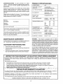
MODEL
NUMBER
SPECIFICATIONS
HORSEPOWER:
20 0
GASOLINE CAPACITY
AND TYPE"
3 5 GALLONS
UNLEADED REGULAR
OIL TYPE (API-SF/SG):
SAE 30 (above 32°F)
SAE 5W-30 (below 32°F)
OIL CAPACITY:
W/FILTER:
40
W/O FILTER: 3 5
SPARK PLUG:
(GAP: 025")
CHAMPION RV17YC
VALVE CLEARANCE:
INTAKE:
003" - 006"
EXHALIST: 013"- 016"
GROUND SPEED (MPH):
917.250261
SERIAL
NUMBER
DATEOF PURCHASE
THE MODEL AND SERIAL NUMBERS WILL BE FOUND
ON A PLATE UNDER THE SEAT
YOU SHOULD RECORD BOTH .SERIAL NUMBER AND
DATE OF PURCHASE AND KEEP IN A SAFE PLACE
FOR FUTURE REFERENCE
MAINTENANCE
AGREEMENT
RESPONSIBILITIES
•
Read and observe the safety rules
-
Follow a regular schedule in maintaining, caring for and
using your unit
•
Follow the instructions under "Customer Responsibihties" and "Storage" sections of this owner's manual
LO
08
14
24
09
HI
18
34
56
22
TRANSAXLE OIL
CAPACITY AND TYPE:
4 QUARTS
SAE 30 API-SF/SG
TIRE PRESSURE.
FRONT: 14 PSI
REAR:
10 PSI
CI'-IARGINGSYSTEM:
5 AMPS BA-!-FERY
5 AMPS HEADLIGHTS
BLADE BOL[ TORQUE:
30-35 FT LBS
WARNING:
This tractor is equipped with an interne!
combustion engine and should not be used on or near any
unimproved forest-covered, brush-covered or grass-covered land unless the engine's exhaust system is equipped
with a spark arrester meeting applicable local or state laws
(if any) If a spark arrester is used, it should be maintained
in effective working order by the operator
A Sears Maintenance Agreement is available on this product Contact your nearest Sears store for details.
CUSTOMER
1st
2nd
3rd
Reverse
In the state of California the above is required by law
(Section 4442 of the California Public Resources Code)
Other states may have similar laws. Federal laws apply on
federal lands A spark arrester for the muffler is available
through your nearest Sears Authorized Service Center/
Department (See REPAIR PARTS section of this manual)
ii
LIMITED TWOYEAR
WARRANTY
ON ELECTRIC
START RIDING EQUIPMENT
For two (2) years from the date of purchase, if this ridingequipment is maintained, lubdcated and tuned up according to the
instructions in the owner's manual, Sears will repair or replace, free of charge, any parts found to be defective in material or
workmanship
This Warranty does not cover:.
',
•
• ".
"'
Expendable itemswhich become worn during qormal use, such as blades, spark plugs, air cleaners and belts.
Tire replacement .oJ"repair caused by punctures from outside objects, Suc.has nails, thorns_stumps, or glass
Repairs neCessary because of operB_torabuse, r_egligence_impro_per_4orageor aceident or the failure to maintain the
ecj.uipm_n{_ccordl_g to the'instructions cbntained in.the owner's manual
"
:
l_[din'ge_Li,'l:_ent_sedfor.c_l_e_lai'_r..r.entatpl:Irp_seS',--_ ._'. ,; :.- i .: . .,:. ,,:
.,;.• _.
.: • 1...
" ,'-
......-
IT
'
'
-:
"
' " "::;:;;--,"; : "
For ninety (90) days from date of purchase, if any battery inciudedv_i.th_h4sridin(} equipment proves defective in matet_alor
workmanship and our testing determlnes the battery will not hoid a charge, Sears will reptace the battery at no charge
WARRANTY SERVICE
CENTERfDEPARTMENT
IS AVAILABLE BY RETURNING
iN THE UNITED STATES
THE RIDING EQUIPMENT
TO THE NEAREST
SEARS SERVICE
This Warranty gives you specific legal rights, and you may aJsohave other rightswhich may vary from state to state
SEARS, ROEBUCK AND CO, 1:)/817WA, HOFFMAN ESTATES, ILLINOIS 60179
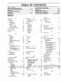
TABLE OF CON!TENTS
SAFETY RULES .......................................................
2
PRODUCT SPECIFICATIONS ....................................... 3
CUSTOMER RESPONSIBILITIES
..................... 3, 15-18
WARRANTY ...................................................................
3
TRACTOR ACCESSORIES ............................................ 5
ASSEMBLY ...............................................................
7-10
OPERATION ..........................................................
11-14
MAINTENANCE SCHEDULE ..................................
15
SERVICE AND ADJUSTMENTS .........................
19-25
STORAGE ...................................................................
25
TROUBLESHOOTING ...........................................
28-29
REPAIR PARTS - TRACTOR ...............................
31-47
REPAIR PARTS - ENGINE ..................................... 48-57
PARTS ORDERING/SERVICE ............... BACK COVER
INDEX
E
A
Accessories
5
Adjustments:
Blake
Carburelor
Clutch Pulfey
Gauge Wheels
Mower
Front-To-Back
Side-To-Side...
Throttle Control Cable
21
25
2t
13
20
19
23
18
Air Filter, Engine
Air Screen, Engine
Assembly
!8
7-10
Operation
Electrical.
Interlocks and Relays
Schematic
Wiring Diagram
Engine:
A_r Filter
Air Screen
Cooling Fins
Oil Change
Oil Level
Oil Type
.
Preparation
Repair Parts
S.tartlng
. .
; . .
Stor'a•ge
:
23
30
32
18
18
18
.. 17
13,17
17
.. 13
48-57
14
26
Operating
t t- t 4
Mower
t 3
Options:
Accessories
Spark Attester
.5
3,40
P
Pinking Brake
Parts Bag
Parts, Replacement!Repair
Product Specifications
12
6
48-57
3
,R
Flepat_ Parts
3 t-47
B
F
Battery.
Charging
Cleaning
Installation.
Levels
Preparation .........
Starting with Weak Battery
Storage ......
Terminals
Beit:
Motion Drive
Removal/Replacement
Mower Drive
Removal/Replacement
Mower Blade Drive
RemovallReplacement
Blade:
Sharpening ,
Replacement
Brake Adjustment
•8
16
• 10
8,17
..8
23
26
16
A_r Filter
Fuel
Oil
Storage
Type
Fuse .
L
16
16
21
Leveling r,4owerDeck
Lubrication:
Chart
.
,_ gJ
. •
. "7, .......
24
19
15
M
25
Clutch Pulley
......
21
Controls, Tractor
...
11
Customel Responsibilities
15-18
Engine:
Air Filter
. : .
11_
_.r. Scree
'
"
.,.
18
•-C6ol(n_) F.[ns, " .:: _..... _.. ;;. ,', 18
.
23
Headlights
Hood Removal/tnslalfation
21
Carburetor Adjustment
-!.
26
12
23
H
C
•
18
18
17
Fuel.
22
20
S
Filter
." "'_::
""."
".° "
. .- ......
Tire Care
Transaxle
Culling
HeighL
17
16
15
. .. 15
8,16,23
16
Mower
12
2
8
Service and Adjustments
Carburetor
Clutch Pulley
..
Fuse ...
Hood Removal/Instaiiation
Motion Drive Belt
Remova]lReplacemenl
Mower Dive Bell
Remova!/Replacement
Mower Blade Drive
Removal/Replacement
Mower Adlustment
Front-to-Back
Side-to-Side
Mower Removal
19-25
25
21
23
24
20
20
. .. 19
Tire Care
Slope Guide Sheet
Spark Plug(s)
..
Specifications
Stadmg the Engine ....
Steering Wheel .........
8,16,23
59
18
3
13-14
7,22
22
20
21
Maintenance Schedule ....
15
Mower:
Adjustment, Front-to-Back
.20
Adjustment, Side-to-Side
19
Stepping the Tlactor
12
Blade Sharpening .......
16
Storage
26
Blade Replacement
"
. 16
12
Cutting Height
,
;
n's'lallatdn
- ..,.,
.
: ..-' 19
_ -°
.
, . .qperat,i6n_..,., ..;',,_,.,::,_:" . ,_:.....,': 1,9,-. "T.hfottle do_trbl _3at_le.A_uS_trienI..o _25,
•
-." "1 " .-'.-'.
:"_': "_' -"_"
"
.'- --.
:.-.. ,_o,.g!"F_er:-,;.. ,,.;.:,: .... _ ........... 1_ .:-. "Mg,.W[}.gTipS".-...
,.;., .; ..... .:.;....,'.::., 14_LLLLLLLL.Iparkl--'I_.g(_)
....
:: ....
lid
Muffet
... ::,
.....
18
Tractor:
Spark Attester'
:3,40
Battery
Blade .
Lubrication
(Dhad
Maintenance
Schedule
Safety Rules
Seat
" " --
_-.:,..,,b,,'_-.=;-.,_......
O
Oil:
4
:." - "_.
i =_ :.
28:,29 "
" 1"6
W
Warranty
Cold Weather Conditions
Engine
Storage
;,-..:.-.:--=---
-'Trouble"Shobting Cha;'.t'. : ", ':
Tra_sax[e
:
:
.
13,17
t7
26
Winng Diagram
Winng Schematic
3
32
30
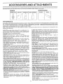
ACCESSORIES
ATTACHMENTS
These accessories and attachments were available through most Sears retail outlets and service centers when the tractor was purchased
Most Sears stores can order these _tems for you when you provide the model number of your tractor
ENGINE
MAINTENANCE
SPARK PLUG
,2
GAS CAN
ENGINE OIL
BLADES
FUEL STABILIZE
BELTS
J;
PERFORMANCE
Sears offers a wide variety of attachments that tit your tractor
you This list was current at the ttme o! puhticat_on; however,
may be made in these attachments, or some may no longer
accessories
and attachments
that are available for your
Most of these attachments do not require addilional hitches
attaching and detaching
Many of these are listed below with brief explanations of how they can help
it may change in fulure years - more attachments may be added, changes
be availabre or fit your model Contact your nearest Sears store for the
tractor.
or conversion kits (those that do are indicated) and are designed for easy
SLEEVE CULTIVATOR is 43 inches wLde Prepares ground !or
seeding, helps weed control Steel frame holds 5 adjuslable
sweeps Adlusls vedically, horizontally..(Requires
sleeve hitch )
"Optional accessory: .steel furrow opener for wider op.enings fo.r
potatoes, cotn, _(nd other d_epseeded crops
SL'EEVE HITCH for use with master lift system
Single pin
couples/uncouples
SNOWTHROWER has 42-inch swath Drum-type auger handles
powdery and web'heavy snow
Mounts easily with simple pin
arrangement
Discharge chute adjusts from tractor seat 6-inch
diameter spout discharges snow 10 to 50 feet Lilt controlled at
tractor seat. (Use with chains and wheel weights and/or rear
drawbar weight )
SPRAYERS use 12-volt DC electric motor that connects to the
tractor battery or other 12-volt source
Includes booms for
automatic spraying and hand held wand for spot spraying Wand
has adjustable spray pattern
For applying herbicides, insecticides, fungicides and liquid fertilizers
SPREADER/SEEDERS
make seeding, fertilizing, and weed kill,nO easy. Broadcast spreaders are also useful for granular deicers and sand
AERATOR promotes deep reel growth for a healthy lawn Tapered 2 5-inch steel spikes mounted on 10-inch diameter d_scs
punctuCe, holes in soil at close intervals to let moisture soak in
Steel weight tray lor increased, pen'etration
BUMPER protects front end of tractor from damage
CARTS make hauling easy
Variety of sizes available, plus
accessories such as side panel kits, tool caddy, cad cover,
protective mat and dolly
CORING AERATOR takes small plugs out of soil to allow moisture and nutrients to reach grass roots
36-inch swath
24
hardened steel coring tips 150 lb capacity weight tray
DISC HARROW has 2 gangs of 4 steel blades that angle from 10
to 20 degrees, 40 inches wide
Can riook 2 units in tandem
(Requires sleeve hitch )
DOZER BLADE removes snow; grades dirt, sand and gravel. 48
inches wide, 17 inches high, clears 44-inch path when angled
Master lilt control lever for operator ease Spring trip for snow
removal on uneven pavement; built-in float for blade to follow
ground contour Reversible, replaceable scraper bar (Use with
hre chains and wheel weights and/or rear drawbar weight )
EASY OIL DRAIN VALVE makes oil changes easier, faster
FRONT NOSE ROLLER canters in front of mower deck to reduce
chances of "scalping" on uneven terrain
GANG HITCH lets you tow 2 or 3 pull-behind altachments at
once, such as sweepers, dethatchers, aerators (not for use with
rollers, carts or other heavy attachments)
MULCH RAKF_JDETHATCHER loosens soil and tlips thatch and
matted leaves to lawn sudace for easy pickup Twenty spring fine
teeth Useful to prepare bare areas for seeding. Avatlable for front
or rear mounting.
HIGH PERFORMANCE
REEL-ACTION
SPRING TINE DETHATCHER covers 36-inch wide path and
tosses thatch into large hopper Mounts behind tractor
PLOW lurns soil 6 inches deep, cuts 10-inch lurrow Crank
adjustment conlrols depth, 3-position yoke sets width Fleav.y
steel lanBside for straight fuirowlng
(Requires s'leeve hitch )_ "
• ,-,_,,ii_ ;..,;.--,_
....
__-. ;-:
.o _-:.....
mcnes .wtoe are op.eraieo lrom
d'rivei-;s seat" Ri_versibl.e "re .elblade can be angled at 30 Begrees
for grading Rev.erses for push_ng snow backwards
(Requires
sleeve hitch )
ROLLER for smoother l_wn sudace.
36-inch wide, 18-inch
diameter water-t_ght drum holds up to 3901bs of weight Rounded
edges prevent harm to tuff Adlustable scraper automatically
cleans drum
nr-..._T'..,,,,_l"l/-,kU_l"l
,;._,.-.
IclLALIt:
tS 'q.2:
SWEEPERS let you collect grass clippings and leaves
TILLER has 8 hp engine to prepare seed beds, cultivate, and
compost garden residue. Chain-drive transmission. Six 11-inch
diameter one piece heat-treated steel tines Tills 30-inch path
(Requires sleeve hitch.) Or use 5 hp tow-behind TILLER with 36inch swath to prepare seed beds, cultivate and compost garden
residue. Tiller has its own built-in lift and depth control system and
does NOT require a sleeve h_tch Fits any lawn, yard or garden
tractor Simply hook up to the tractor drawbar and go[ Optional
accessories for 5 hp tiller convert unit for dethatching, aerating,
hilling, without tools
TIRE CHAINS are heavy duty; closely spaced extra-large cross
links give smooth ride, outstanding traction
" TRACTOR CAB has heavy duty vinyl fabric over tubqlar steef
frame, ABS plastic.top; Clear plastic windshield.off_r_ 360 degfe_:
, prote&lor _n-summer,
-
r_,-z_n_r
thh=nH'"
......
r4--k/_l_[a{'_
.Opt_al
t_il=ee"
ac!_es_ories
" _,_r_4ehi_l',4
"
"
_'i_t
" "
_1_2'_'
'v_o_ea_mS;eircau_;nUl:g_io"r'moun;_'_';;;;
"
nclt._de. -t_nt
'h¢_l_
"
"
: "
;
wiper,
;_o_; rated
VACS Ibr powerful collection of heavy grass clippings and leaves:
Optional wand attachment
to pick tJp debris in hard-to-reach
places VAC/CHIPPER includes a chipper-shredder
WEIGHT BRACKET for drawbar for snow removal applicaf_ons
Can be mounted on trent of tractor for ptowing apphcations Uses
(1) 55 Ib weight
WHEEL WEIGHTS for rear wheels prowde needed traction for
snow removal or dozing heavy materials
5
;
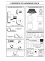
CONTENTS
OF HARDWARE
PACK
,,,,,,,,,, i, u [,
ii,
Parts Bag contents
shown full size
Parts packed
ill,lllli,
separately
in carton
0
Seat
(1) Shoulder
Bolt
Battery acid
5t16-18
\
u_
\
I
(1) Knob
Battery
Steering Wheel
(1) Washer
r
"i7/32 x 1-3116 x 12 Gauge
Double Loop
3) Retainer Springs
(_
J
Parts Bag
Owner's Manual
i
Parts bag contents
(2) Gauge Wheelsi!j//
(4) Retainer Springs
Single Loop
--._J
(2) Shoulder Bolts
_(2)
,r
(2) Hex Bolts 1/4-20 x 3/4
i
ii
not shown
full size
©
_
(2) Washers Lock Nits
3/8 x 7/8 x 14 Gauge
Front Link Assemblies
,_----
(2) Battery Carriage Bolts 1/4-20 x 7-1/2
Steering
Sleeve
(2) Hex Nuts 114-20
Te#minal Guard
St._erin_lW_.eel Insert.
(-;_)Washe_.s "_/32 x 5/8 x 16 Ga.
•
"=
i _
t
i
r
;
,11
,
:
"
. ,: .":
.. ,...
; .:; .... .._,._ - +.: ...._..:_ .,['-.__,.._ -..,_-,..
i
I
---
(2) Wing Nuts 114-20
.
Q
15 ° Slope Sheet
i
Battery Caps
and Instructions
:
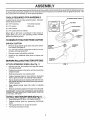
ASSEMBLY
iiiiii
J,
i
iiiiiiii
iiiiiiiiiiii
, i i I,IIIIIIl,lI,JUJIJl,ll,lll,I
Your new tractor has been assembled at the factory with the exception of those parts left unassembted for shipping purposes,.
To ensure safe and proper operation of your tractor all parts and hardware you assemble must be tightened securely Use
the correct tools as necessary to insure proper tightness.
TOOLS
REQUIRED
FOR ASSEMBLY
STEERING
WHEEL INSERT
A socket wrench set wilt make assembly easier. Standard
wrench sizes are listed.
i
(2) 7/16" wrenches
Tire pressure gauge
(I)
Utility knife
1/2" wrench
__
_
HEX BOLT
(1) 9/16" wrench
(t)
3/4" socket with drive ratchet
When right or left hand is mentioned in this manual, it
means when you are in the operating position (seated
behind the steering wheel),
TO REMOVE TRACTOR FROM CARTON
UNPACK
•
CARTON,
' STEERING
,R(_move ali acces.sible Io0se parts and parts car;tons
from .carton (See #age 6),,"
"
Cut, fron:l top io bottor_, al6ng lines on _II four corners
of carton, and lay panels flat.
•
Remove mower and packing materials
•
Check for any additional loose parts or cartons and
remove,,
/
STEERINGY
SLEEVE /
BEFORE ROLLING TRACTOR OFF SKID
ATTACH
STEERING
WHEEL
Remove hex bolt, lock washer and large flat washer
from steering shaft
-
Position front wheels of the tractor so they are pointing
straight forward,
•
Slide steering sleeve over steering shaft.
•
Position steering wheel so cross bars are horizontal
(left to right) and slide onto steering wheel adapter,;
•
Secure steering wheel to steering shaft with hex bolt,
lock washer and large flat washer previously removed.
Tighten securely.
•
Snap steering
wheel.
wheel insert into center of steering
•
Remove protective plastic from tractor hood and grill•
IMPORTANT: CHECI< FOR AND REMOVE ANY STAPLES
IN SKID THAT MAY PUNCT.URE TIRES WHERETRACTOR
1S.TO ROLL OFF. SKID.
-"
•
°
l
STEERING
I/'
Releas_ p_.r_ing brake :by delsres_ing c[u_tchi15rake
pedal
Place gearshift lever _nneutral (N) position
Rotl tractor backwards off skid.
7
f
,I - - t_
/
/
FIG. 1
(See Fig. 1)
•
- _I
ASSEMBLY
HOW TO SET UP YOUR TRACTOR
PREPARE
BATTERY
,NN,mm,ll
INSTALL
Adjust seat before tightening adjustment knob_
(See Fig. 2)
II
CAUTION:
Wear eye and face shield.
Wash hands or clothing immediately if
acc identally in contact with battery acid.
Do not smoke. Fumes from charged
battery acid are explosive.
Read the instructions included with the
battery vent caps° Always wear gloves,
clothing and goggles to protect your
hands, skin and eyes•
,i,1,1,,ill
i
mira
SEAT (See Fig. 3)
ii
°
Remove cardboard packing on seat pan..
°
Place seat on seat pan and assemble shoulder boll
o
Assemble adjustment knob and flat washer loosely.
Do not tighten.
"
Tighten shoulder bolt securely.
',
Lower' seat into operating position and sit on seat°
•
Slide seat until a comfortable position is reached which
allows you to press clutch/brake pedal all the way
down.
°
Get off seat without moving its adjusted position
•
Raise seat and tighten adjustment knob securely.
Your tractor' has a battery charging system which is sufficient for' no{real use. However, periodic charging of the
battery with an automotive charger' will extend its life.
•
'-
See instructions packed with vent caps. in parts bag,
Fill battery with acid. Fill each celt until it reaches the
Bottom o.f the vent Wells. Do not overfill,
-
Allow battery to stand a,nd settle for; at least thirty
minutes After standing, check the battery cell acid
level If below the vent wells, add more acid until the
correct Ievel is reached.
SEAT
While battery is standing (after adding acid) and later, while
battery is being charged, continue with assembly of unit.
IMPORTANT:
TO MAXIMIZE THE LIFE OF YOUR
BATTERY, IT IS NECESSARY THAT THE BATTERY BE
CHARGED BEFORE USE. FA1LURE TO CHARGE
BATTERY CAN RESULT IN A SHORTENED BATTERY
LIFE
•
Charge battery at a rate of 6 amperes for 1 hour.• Use
a 12 volt battery charger. Observe all safety precautions required for battery charging.
•
Check the acid level after the battery is charged. If the
acid has fallen below the correct level, add distilled or
iron free water_.
•
Install the vent caps to cover the vent wells. Wash the
top of the battery with water to remove any acid, then
wipe dry.
•
Check battery case for leakage to make sure that no
damage has occurred in handling.
•
Dispose of excess battery acid. Neutralize acid for
disposal by adding it to two gallons of water in a five
gallon plastic container, Stir with a wooden or plastic
paddle while adding baking soda until the addition of
rno.re soda causes no more foaming.
•
ADJUSTMENT
KNOB
FIG. 3
CHECK
The tires on your tractor were overinflated at the factory for
shipping purposes,, Correct tire pressure is important for
best cutting performance.
•
• •
_
r__/CELL
FIG. 2
BRAKE
SYSTEM
After you learn how to operate your tractor, check to see
that the brake is properly adjusted. See "TO ADJUST
BRAKE" in the Service and Adjustments section o! this
manual.
BATTERY
_
Reduce tire pressure to PSI shown in "PRODUCT
SPECIFICATIONS" on page 3 of this manual,,
CHECK
Fb.llow in'structior_s 6r_how to _'sfall ba'.ttery. : : ..:
-]_
TIRE PRESSURE
ACID
8
i,ii
ill,,llll
i
iiiii ,
__
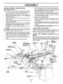
ASSEMBLY
iii
i i
INSTALL
(See
Figs.
MOWER
4 and
Ill
AND DRIVE BELT
•
7')
Be sure tractor is on level surface_ Engage parking brake.
•
Cut and remove tie down securing anti-sway bar.
Swing anti-sway bar to left side of mower deck
•
Relieve idler tension from belt. Push idler forward and
place a block (standard wood 2 x 4 or equivalent)
behind idler pulley,,
•
Slide mower undertractorwith discharge guard to right
side of tractor,,
.
Swing L.H. gauge wheel bar forward by removing rear
retainer spring and pin.
•
Install one front link in top hole of the LH. front mower
bracket and LH• front suspension bracket, Retain with
two single loop retainer springs as shown.
•
Slide right side of mower deck forward, toward R.H,
front tire,,
IMPORTANT: CHECK BELT FOR PROPER ROUTING IN
ALL MOWER PULLEY GROOVES. INSTALL BELTINTO
ELECTRIC CLUTCH PULLEY GROOVE
°
•
•
o
•
•
DECK LEVELNESS
Forbest cutting results, mower housing should be properfy
leveled,
See 'q'O LEVEl' MOWER HOUSING" in the
Service and Adju.stments section' of this manual.
R_,Hr:
DOUBLE LOOP
RETAINER SPRING
IIIIII
arms on inward pointing deck
pins° If necessary, rock and raise front of mower to
align deck pins with the holes in suspension arms,,
Retain with double loop retainer springs,,
Connect anti-sway bar to chassis bracket under left
footrest and retain with double loop retainer spring.,
Turn height adjustment knob clockwise to remove
slack from mower suspension_
Raise deck to highest position°
Swing LH,, gauge wheel bar back towards rear of
mower and secure with pin and retainer spring removed earlier,,
Assemble gauge wheels as shown using long shoulder
bolts, 3/8 washers and 3/8-16 center Iocknutso Tighten
secure3y,
Adjust gauge wheels before operating moweras shown
in the Operation section of this manual,
CHECK
-" " Install second'fi'ont link in the top hole of.the
f_ont
mower" bracket'and
RN.'frOnt suspenson bi'ackeL
Retain With two single loop retainer springs as shown,
•
Carefully remove block from behind idler pulley,
•
Turn height adjustment knob counterclockwise until it
stops,
•
Lower mower linkage with attachment lift tever,
CHASSIS
BRACKET
Place the suspension
CHECK
FoR
PROPER
POSITION
OF ALL
See the figures that are shown for replacing motion, mower
drive, and mower blade drive belts in the Sewice and
Adjustments section of this manualo Verifythat the betts are
routed correctly,
FRONT
SUSPENSION
SUSPENSION
ARMS
DOUI_LE LOOP
RETAINER SPRING
(Inward Pointing
Deck Pins)
F_RONT
LINKS
BRACKET
ELECTRIC
CLUTCH
WHEEL
BAR
L.H. GAUGE
FRONT
SUSPENSION
BRACKET
/
SHOULDER
BOLT
SINGLE
LOOP RETAINER
SPRINGS
FRONT MOWER
BRACKET
CENTER
t.OCKNUT
ANTI-SWAY
BAR
GAUGE
WHEEL
BLOCK"
(Wood 2 x 4 or equiv,)
DISCHARGE
GUARD
FIG. 4
9
ASSEMBLY
INSTALL
BATTERY
, ,
A
,
(See Figs. 5 and 6)
,,,
,
CAUTION: Do not short battery termi-nals. Before installing battery, remove
metal bracelets, wristwatch bands°
rings, etc.
WING NUTS
Positive terminal must be connected
first to prevent sparking from accidental grounding.
Lift hood to raised position.
•
Be sure battery drain tube has not come loose and is
securely attached to drain in battery tray..
•
Lower battery into battery tray with terminals to front of
tractor
•
First connect RED battery cable to positive (+) battery
terminal with hex bolt, flat washer, lock washer and hex
nut as shown: Tighten securely..
•
Connect BLACK gr.ounding cable to negative (-) battery
,terminal with remaining hex bolt, fiat washer, lobk.
washer and. hex nut. Tighten securely',
i
"
•
Slide the two batter_ b61ts through the terminal guard
and start the wing nuts onto the threads_
•
Position terminal guard over battery as shown, tower
battery bolts into key holes and slide square shafts of
battery bolts into slots of key holes.
•
Inspection for secure connections
ware).
Inspection for' corrosion..
•
Testing battery.
•
Jumping (if required).
•
Pedodic charging,.
.
-"_
s
• o.," °°
:"
•"-.
-;,.
:
!
t.
DOORSACCESS
-BAT_ERYTRAY
FIG. 6
•.
PLEASE REVIEW THE FOLLOWING
(to tighten hard-
/
*TI_(NEGATIVE)
CHECKLIST:
V" All assembly instructions have been completed..
,/
•/
No remaining loose parts in carton..
Batteryis properly prepared and charged.
1 hour at 6 amps).
,/
Seat is adjusted comfortably and tightened securely
(Minimum
V" All tires are properly inflated. (For shipping purposes,
the tires were overinflated at the factory)°
,/
Be sure mower deck is properly leveled side4o-side/
flont-to-rear for' best cutting results. (Tires must be
properly inflated for' leveling)
,/
Check mowerand drive belts. Be sure they are routed
properly around pulleys and inside all belt keepers..
,/
Checkwiring. See that all connections are still secure
and wires are prepedy clamped..
FLAT WASHER
/
2 "f-_"
VCHECFJ.lST.
BEFORE YoU 'OPERATE A_D ENJOY" YOUF_ N#W
TRA C_OR_ WE WISH TO ASSURE THAT YOU RECEIVE
THE BEST PER FORMA NCE A ND SA TISFA CTtON FROM
THIS QUALITY PRODUCT
WHILE LEARNING .HOW TO USE YOUR TRACTOR,
PA Y EXTRA ATTENTION TO THE FOLLOWING IMPORTANT ITEMS:
(POSITIVE)
RED CABLE
V'
,/
•,,
TERMINAL
,_UARD
*
KEYHOLE
Tighten wing nuts by hand making sure battery bolts
remain in slots of the key hotes in the battery support.
B'e sureterminaf access doers are closed.
•
"
BATTERYBOLT_.
Use terminal access doors for:
•
"" .......
"""
CAPS
•
•
....... :""
Engine oil is at proper level.
Fuel lank is filled with fresh, clean, regular unleaded
gasoline ....
_
....
, . : _'. Become familia.f v_ith:_{..9:bhtiols. ,.their _ca.tip_ end :,:.
• "-',7'-Be _ure brak_ s_stem _s_n'.safeoperatlng c.ond_tlPn. ,
LOCK WASHER
FIG. 5
10
OPERATIC
i
i
i.m
i
i ..H,,,,,,,i
I,,H I
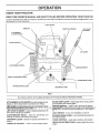
KNOW YOUR TRACTOR
READ THIS OWNER'S
MANUAL
AND SAFETY
RULES BEFORE
OPERATING
YOUR TRACTOR
Compare the illustrations with your tractor to familiarize you rself with the locations of various controls and adjustments, Save
his manual for future reference,
LIGHT S_ITCH
AMMETER
ATTACHMENT
CLUTCH
THROTTLE
X
X
CONTROL
LIFT LEVER
_ - -
SWITCH
_.
CHOKE CONTROL__
-, _
iI
,.
y
,
CLUTCH/BRAKE
LIFT LEVER
,
PEDAL
IGNITION SWITCH
HEIGHT ADJUSTMENT
KNOB
RANGE SHIFT LEVER
PARKING
BRAKE LEVER
GEARSHIFT
LEVER
FIG. 7
Our tractors conform to the safety standards of the American National Standards Institute.,
A'ItTACHMENTCLUTCH
SWITCH-Usedto.engagemower
blades or other attachments
RANGE SHIFT LEVER _ Allows high (H) or Iqw (L) speed
mounted to ybur tract.o_,_ ,
f9[. all_forvva[d ahcl rev,erse gear,s. "'
'
: '.
LIFT L._VER¢LUNGE, R -; 0sed_6_'eiea,_ ;_t:t&cSmentlift
lever wheh changing its p.Qsitibn,,
CLUTCHtBRAKE
PEDAL - Used for declutching and
braking the ti'actor ahd starting the engine,
('_:' ""
,:
" ""
" '
':" , i
"' : ":"-" " _':"
LIGHT SWITCH - Turns the h'eadlights on ahd off,
GEARSHIFT
tractor.
CHOKE CONTROL - Used when starting a cold engine
THROTTLE
,
pARKING BRAKE LEVER - Locks ctL_tcb/brake pedal into
the brake position,
LEVER - Selects the speed and direction of
HEIGHT ADJ USTM ENT KNOB - Used to adjust the mower
height,
CONTROL - Used to control engine speed,
't '1
OPERATION
The operation of any tractor can result in foreign objects thrown into the eyes, which can result
in severe eye damage. Always wear safety glasses or eye shields while operating your tractor
or performing any adjustments or repairs. We recommend a wide vision safety mask for over
the spectacles or standard safety glasses.
HOW TO USE YOUR TRACTOR
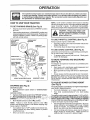
TO SET PARKING
-
BRAKE
(See
NOTE: Under certain conditions when tractor is standing
idte with the engine running, hot engine exhaust gases may
cause "browning" of grass. To eliminate this possibility,
always stop engine when stopping tractor on grass areas.
Fig, 8)
Depress clutch/brake pedal into full "BRAKE" position
and hold,
CAUTION:
Always stop tractor completely, as described above, before leaving the operator's position; to empty
grass catcher, etc.
Place parking brake lever in "ENGAGED" position and
release pressure from clutch/brake pedal. Pedal should
remain in "BRAKE" position.. Make sure parking biake
wilt hold vehicle secure.
ATTACHMENT
CLUTCH
SWITCH
"ENGAGED"
POSITION
TO USE THROTTLE
"DISENGAGED"
POSITION
_L
THROTTLE
h--*C)NTROL,LEVIER
TO MOVE FORWARD
(See Fig, 8) :
POSIT|ON
\
HEIGHT ADJUSTMENT
KNOB
GEARSHIFt
RANGE
SHIFT
LEVER
AND BACKWARD
•
Slowly release clutch/brake pedal to start movement.
IMPORTANT: BRING TRACTOR TO A COMPLETE STOP
BEFORE SHIFTING OR CHANGING GEARS. FAILURE
TO DO SO WILL SHORTEN THE USEFUL LIFE OF YOUR
TRANSAXLE.
LEVER
FIG. 8
STOPPING
iSee Fig. 8)
The direction and speed of movement is controlled by the
gearshift lever'.
o
Start tractor with clutch/brake pedal depressed and
gearshift lever in neutral (N) position.
•
Move gearshift and range shift levers to desired position
"DISENGAGED"
POSITION
POSIT
CONTROL
Use choke control whenever you are starting a cold engine..
Do not use to start a warm engine.
•
To engage choke control, pull knob out. Slowly push
knob in to disengage.
PARKING
BRAKE
"ENGAGED"
CLUTCH/BRAKE
PEDAL "BRAKE"
POSITION
(See Fig. 8)
Full throttle otf.ers the'bffst m0weF Rerfo[mance.
TO USE CHOKE
/
CONTROL
Always operate engine at full throttle
•
Operating engine at less than full throttle reduces the
bakery qharging rate
TO ADJUST MOWER
(See Fig. 8)
(See Fig. 8)
CUTTING
HEIGHT
The cutting height is controlled by turning the height adjustment knob in desired direction.
•
Turn knob clockwise (f_l) to raise cutting height.
•
Turn knob counterclockwise (1_,) to lower cutting
GROUND DRIVE.
.
.
.
height ....
"
. .
. .. ::
IL
".0
D.ep[ressdtutc_brake .l_edal:ir_tofull' I_BRAKE f,_p6si_iqn, .
1"he_tt nh he nht rann_ ts_inDtr_x rna(el,_ 1,1/4 .I to 4.-':}.].4
;,-,Mgv_g_.q_._ ifI.=.!.e,_.er:t
_ ne'_t_al:([g)posltl.e_:. ;t;:
;_,-.1_,:..
:-:4".:The._ei'ghts:;are_.e_s.u[_ (ro_'_.e:gi'¢u_ tQt_rbbI_p..,
•EI_tN_.
V: ..'_',:;,:"..;:4;. ..?y ;: ; . _:,_:,;...'-'[:
"'oy.:,: .: :.:.:",..,,: r' _" _._€.i_h'_f,he:'_!3g._._.0q_
rU_llhg: .'Tl_s.e rhetgh,_;are_p_¢0"_l.;- ....
,_.: Mo_;e:'th[Sttle:'86ritiSi io's 6w i._;)position"
""
'
" mate and m_y. _i_ de#ending upon soi!cbnditlons.', Height :
• • Failure
' " "to move
" throttle
" "
'
I to SlOW
, , .1.,_.)..
or
:.
NOTE
contro
. grass ana [ypes Q_grass uemg mowea,.'
•
The average lawn should be cut to approxirn ely 2-1/2
position and allowing engine to idle 6efore stopping rna.y
inches during the cool season and to over 3 inches
cause engine to "backfire"..
during hot months. For healthier and better looking
o Turn ignition key to "OFF" position and remove key.
lawns, mow often and after moderate growth..
Always remove key when leaving tractor to prevent
For best cutting performance, grass over 6 inches in
unauthorized use.
height should be mowed twice. Make the first cut
•
Never use choke to stop engine..
relatively high; the second to desired height.
MOWER BLADES •
Move attachment clutch switch to "DISENGAGED"
position.
12
I=,,I,' H=' =
,IIHH==,=H =' =
OPERATION
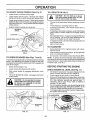
TO ADJUST
GAUGE
WHEELS
(See Fig, 9)
•
•
Adjust mower to desired cutting height
Lower mower with lift control. Remove rear retainer
spring and clevis pin which secure each gauge wheel
•
Lower gauge wheels to ground.. Raise gauge wheels
slightly to align holes in bracket and gauge wheel bar
and insert clevis pins. Gauge wheels should be slightly
off the ground
=
TO OPERATE
H=
hills
with slopes
greater
15down
° and
CAUTION:
Do not
drive than
up or
do not drive across any slope.
Replace retainer springs into clevis pins..
Choose the slowest speed before starting up or down
hills.
•
Avoid stopping or changing speed on hills.
If slowing is necessary, move throttle control lever to
siower position.
If stopping is absorutely necessary, push clutch/brake
pedal quickly to brake position and engage parking
brake
•
"_.
•
GAUGE WHEEL B_
•
GAUGE
WHEEL'
I
-
RETAINER
SPRING
ON HILLS
Move gearshift lever to 1st gear and range shift lever to
low (L) position.. Be sure you have altowed room for
tractor to roll slightly as you restart movement.
To restartmovement, slowly release parking brake and
otutch/brake pedal
Make a!i turns s!owly.
TO TRANSPORT
•
BRACKET
MOWER
lift to highest position with attacl_-
•
When pushing or towing your tractor, be sure gearshift
lever is in neutral (N) position,
•
Do not push or tow tractor at more than five (5) MPH.
NOTE: To protect hood from damage when transporting
yourtractoron a truck or atrailer, be sure hood is closed and
secured to tractor. Usean appropriate means of tying hood
to tractor (rope, cord, etco)o
FIG, 9
TO OPERATE
Raise attachment
ment lift control
(See Figs. 7 and 8)
Your tractor is equipped with an operator presence sensing
switch. Any attempt by the operator to leave the seat witfl
the engine running and the attachment clutch engaged will
shut off the engine.
BEFORE
•
•
Select desired height of cut°
Lower mower with attachment lift control
•
Start mower blades by engaging attachment
control
•
TO STOP MOWER BLADES - disengage attachment
dutch control,.
CHECK
dutch
•
•
•
CAUTION: Do not operate the mower
without either the entire grass catcher,
on mowers so equipped, or the discharge guard in place.
•
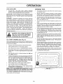
STARTING
ENGINE
THE ENGINE
OIL LEVEL (See Fig. 11)
The engine in your tractor has been shipped, from the
factory, already filled with summer weight oil
Check engine oil with tractor on Ievel ground_
Remove oil fill cap/dipstick and wipe clean, reinsert the
dipstick and push it all the way down into the tube, wait
for a few seconds, remove and read. oil level. If
necessary, add oil until "FULL" mark on dipstick is
reached° Do not overfill
For cold weather operation you should change oil for
easier starting (See "OIL VISCOSITY CHART" in the
Customer Responsibilities section of this manual).
.To change engine oil, see the Customer Responsibili•ties section in this manual,
• DISCHARGE
GUARD
FIG. 10
FIG, 11
13
ill,
,,,
ii,
=
OPERATION
ADD
GASOLINE
MOWING
-
Filt fuel tank. Use fresh, clean, regular unleaded
gasoline (Use of leaded gasoline wi!l increase carbon
and lead oxide deposits and reduce valve life)
IMPORTANT: WHEN OPERATING IN TEMPERATURES
BELOW 32°F{0°C), USE FRESH, CLEAN WINTER GRADE
GASOLINE TO HELP INSURE GOOD COLD WEATHER
STARTING
WARNING:
Experience indicates that alcohol blended
fuels (called gasohol or using ethanol or' methanol) carl
attract moisture which leads to separation and formation of
acids during storage.. Acidic gas can damage the fuel
system of an engine while in storage To avoid engine
problems, the fuel system should be emptied before storage of 30 days or longer. Drain the gas tank, start the
engine and let it run until the fuel lines and carburetor are
empty. Use fresh fuel next season See Storage Instructions for additional information.
Never use engine or
carburetor cleaner products in the fuel tank or permanent
damage may occur
......
,,,,N,,N I =
•
Tire chains cannot be used when the mower housing
is attached to unit
•
Mower should be properly leveled for best mewing
performance. See "TO LEVEL MOWER HOUSING" in
the Service and Adjustments section of this manual
•
Use the runner on the right hand side of mower as a
guide.. The blade cuts approximately an inch outside
the runner (See Fig. 10).
The left hand side of mower should be used for trimrning_
•
qAuTI'dN_
l=ill to bottom of gas tank"
filler' neck: Do'not Overfill: Wipe Off a.ny
spilled oil or fuel. Do not store, spill or
use gasoline near an open flame. '
°
Drive so that clippings are discharged onto the area
that has been cut. Have the cut area to the right of the
machine. This will result in a more even distribution of
clippings and more uniform cutting.
•
When mowing large areas, start by turning to the right
so tha,t clippings wilt discharge away from shrubs,
fences,, driveways, etc. After one or two rounds, mow
in t'he opposite di.rection making lef! hand turns until
" finished (See Fig...12).
: .....
.:. - if g.ra.sSis extremely tall, °i'[s.h_Suldrbemowed twiCeto
r.educe load and possible fire hazard from dried clit3pings.. Make first cut relatively high; the second to the
desired heigh!.
Do not mow grass when it is wet, Wet grass wilt plug
mower and leave undesirable clumps.. Allow grass to
dry before mowing.
.
.................
•
TO START
ENGINE
(See Fig. 8)
When starting engine for the first time or if engine has run
out of fuel, it will take extra cranking time to move fuel from
the rank'to the engine
•
Depress clutch/brake pedal and set parking brake.
•
Place gearshift lever' in neutral (N) position..
•
Move Attachment clutch to "DISENGAGED"
•
Pull choke control out to choke (I\!) position for' cold
engine start. For warm engine start do not use choke
control
°
Move throttle control to midway between fast ('_) and
siow (._=,) positions
•
lnsert key into ignition and turn keyclockwiseto"STAR'F'
position and release key as soon as engine starts. Do
not run starter continuously for more than fifteen
seconds per minute° If engine does not start after
several attempts, move throttle control to fast (,_,)
position, wait a few minutes and try again.
position..
•
When engine starts, slowly push choke control in_
•
.
Move throttle control to fast ("¢e_)Position°
Allow e;qgin.e to _ar'm up for a few m n;utes befbre
ehg&ging.d[iv6.b.r_att_ehme_his.:. "'. . :_ .'".".
".
•
Always operate engine at fu[I throttle when mowing to
"&ssurebetter rndv_irig' performance And proper discharge of materia!° Regulate ground speed by selecting a low enough gear to give the mower cutting
performance as well as the quality of cut desired
•
When operating attachments, setect a ground speed
that will suit the terrain and give best performance of
the attachment being used..
f
t_mpe_tures. (hers_..32 F)€._e _cArburet:or-fuel m_x'ture.
may heed i:obe ad/ubte_l for best origin615effor_'anc- e.. Cee _
:"TO AD_LJST.CARBURETOR" in the Se_:vice and Adjustme6ts sectiod of this manual
14
TIPS
CUSTOMER
ii
llllm,l,,
RESPONSIBULITmES
i ii, ,,
,,i i
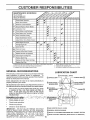
MAINTENANCE
SCHEDULE
.,_ ._/_
F,LL,N
OATES
AS YOU COMPLETE
REGULAR SERVICE
Check
'_'_
a
Sharpen/ReplaceMower Blades
A
LubricationChart
m Check Battery
Level/Recharge
0
Clean Battery
and Terminals
a
CheckTransaxle Coo]lng
.....
Motion Drive Belt(s) Tension
_
O'_
DATES
Chan_e
Engine
"
i/'
,
.
v'
v'
Check Engine Oil Level_
J
Oil
Glean Air Filter
'Replace
""
Tension
Biade Belt(s)
Adjust
I
_"
!/
Adjust
Inspect
_
.................
I/
Check for LooseFasteners
clean
'_
Brake Operation
T
G
_"
i,i,
_.__
J_4_.,_SERVICE
Check Tire Pressure
N
__/__o_
,,Nii,m
*"
:' ,
Air Screen
' '
Muffler/Spark
Attester
Oil Filter (If equipped)
n
e C,eEng,oe
° Coo'i"g::, 'i,iS
RePlace
Spark Plug
ReplaceAft Filter PaperCartridge
Replace
v'
Fuet Filter
1 - Change more ellen when operaling under a heavy lead or in high ambient temperatures
2 - Service more often when operating in di_y or dusty conditions
3 - If equipped with ell filter, change oil every 50 hours
GENERAL
RECOMMENDATIONS
LUBRICATION
The warranty on this tractor does not cover items that have
been subjected to operator abuse or negligence.
To
receive full value from the warranty, operator must maintain
tractor as instructed in this manual.,
(_TIE
(_
Some adjustments will need to be made periodically to
properly maintain your tractor°
properair-fueJ
mi.xtureand
.::addl_st
o'dger_:
"
, helpyou_engine'run
"; .,,
_ .
'1".
:CheE:k
erlb[ne
o!l ievei;
:
•
Check brake operation:,
•
•
Check tire pressure.,
Check for loose fasteners.
::
,
'
'
_'
:
NDLE ZERK (_)
®
BEARING ZERK
li""
(_) STEERING
SECTORGEAR
TEETH
bette_
" .t
:
ROD BALL JOINTS
_._'t::"
BEARINGZERK
Once a year you should replace the spark plug, clean
or replace air filter, and check blades and belts for
wear...A ne'w spark plug and clean air filter assure
CHART
SPINDLE ZERK --
(_) FRONTWHEEL
All adjustments in the Service and Adjustments section of
this manual should be checked at least once each season.
•
4 - Replace blades more ellen when mowing in sandy soil
5 - If equipped with adjustable system
6 - NOI required it equipped with maintenance-free battery
,.,
..
ENGINE (_)
:
" _: '.1 TB_NSAXLE""F:LUID
"
'
IMPORTANT:
DO NOT OIL OR GREASE THE PIVOT
POINTS WHICH HAVE SPECIAL NYLON BEARINGS.
VISCOUS LUBRICANTS WILL ATTRACT DUST AND DIRT
THAT WILL SHORTEN THE LIFE OF THE SELFLUBRICATING BEARINGS. IF YOU FEEL THEY MUST
BE LUBRICATED,
USE ONLY A DRY, POWDERED
GRAPHITE TYPE LUBRICANT SPARINGLY
'15
(_SAE
30 MOTOR OIL AP! _ SF/SG
(_ GENERAL PURPOSE
GREASE
(3) REFER TO CUSTOMER
(_)SPRAY
SILICONE
RESPONSIBILITIES
LUBRICANT
"ENGINE"
SECTION
(MOVE BOOTS TO LUBRICATE)
i
i
i
IIL'J'JI'LUUJII=
CUSTOMER
U,JLUUULUUe'ILU
RESPONSIBILNTIES
UJlL_
TRACTOR
-
Always observe safety rules when performing any maintenance,
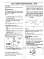
The blade can be sharpened with a file or on a grinding
wheel Do not attempt to sharpen while on the mower,
o
To check blade balance, you will need a 5/8" diameter
steel bolt, pin, or a cone balancer. (When using a cone
balancer, follow the instructions supplied with ba!ancer)_
•
Slide blade on to an unthreaded portion of the steel bolt
or pin and hold the bott or pin parallel with the ground.
If blade is balanced, it should remain in a horizontal
position_ if either end of the blade moves downward,
sharpen the heavy end until the blade is balanced,
BRAKE
OPERATION
tf tractor requires more than six (6) feet stopping distance
at high speed in highest gear, then brake must be adjusted
(See "TO ADJUST BRAKE" in the Service and Adjustments section of this manual)
TIRES
•
Maintain proper air pressure in all tires (See "PRODUCT SPECIFICATIONS" on page 3 of this manua!).
•
Keep tires free of gasoline, oil, or insect control chemicals which can harm rubber_
•
Avoid stumps, stones, deep ruts, sharp objects and
other hazards that may cause tire damage
BLADE
NOTE: Do not use a nail for balancing blade. "['helobes of
the center hole may appear to be centered, but are not,
CENTER
CARE
HOLE
5/8" BOLT
QR PIN "
BLADE
./J
For best result.s mow.e_ blades n'tust b e k__.lEt,sharp,,Repl_¢e b,ent or damaged blades
BLADE
REMOVAL
(See
Fig. 13)
•
Raise mower to highest position to allow access to
blades
•
Remove hex bolt, Iockwasher and flat washer securing
blade°
•
Install new or resharpened bade with trailing edge up
towards deck as shown,
•
Reassemble hex bolt, lock washer and flat washer in
exact order as shown,
FIGo 14
V-BELTS
Check V-belts for deterioration and wear after 100 hours
and replace if necessary. The belts are not adjustable.
Replace belts if they begin to slip from wear,
TRANSAXLE
•
Tighten bolt securely (30-35 Ft Lbs torque)
iMPORTANT: BLADE BOLT iS GRADE 8 HEATTREATED
Keep transaxle free from build-up of dirt and chaff which
can restrict cooling,
NOTE: We do not recommend sharpening blade- but if you
do, be sure the blade is balanced
CHECK TRANSAXLE
(See Fig. 15)
MANDREL
ASSEMBLY
BLADE
COOLING
•
Block up rear axle securely or use a tractor jack°
•
Remove left rear wheel by removing hub bolts_
•
Remove filler plug from transaxle. Oil level must be
even with plug threads. If necessary, fill with SAE 30
motor oil, API-SF or SG. Replace filler plugo
Reassemble wheel to hub_
TRAILING
EDGEUP
•
•
For approximate capacity see "PRODUCT
CATIONS" on page 3 of this manual
,
TO SHARPEN
BLADE
OIL LEVEL
O
(See Fig. 14)
Care should be taken to keep the blade balanced
An
unbalanced blade wilt cause excessive vibration and eventual damage to mower and engine,
FIG, 15
16
SPECIFI-
i ill,i
i,_
M
i
(See Fig. 16)
_,_l
I
IIIll
,
I
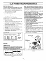
NOTE: Although multi-viscosity oils (5W30, 10W30 etc)
improve starting in cold weather, these multi-viscosity oils
will result in increased oil consumption when used above
32°F. Check your engine oil level more frequently to avoid
possible engine damage from running low on oil
Your tractor has a battery charging system which is sufficient for normal use_ However, pedodic charging of the
battery with an automotive Charger will extend its life,
•
IIIII
RESPONSiBiLiTiES
CUSTONIE
BATTERY
HH_I ,I
Acid solution level in each battery celt should be even
with bottoms of vent wells. Add only distilled oriron free
water if necessary° Do not overfill
•
Keep battery and terminals clean
•
Keep battery bolts tight
•
Keep vent caps tight and small vent holes in caps open.
Change the oil after the first two hours of operation and
every 50 hours thereafter or at least once a year ff the
tractor is not used for 50 hours in one year.
Check the crankcase oil level before starting the engine
and after each eight (8) hours of operation° Tighten oil fill
cap/dipstick securely each time you check the oil level
•
Recharge at 6 amperes for I hour,
TO CLEAN BATTERY AND TERMINALS -
TO CHANGE ENGINE OtL (See Figs. 17 & 18)
Determine temperature range expected before oit change
All oil must meet APt service classification SF or SG
Corrosion and dirt on the battery and terminals can cause
the battery to "leak" power
•
Remove terminal guard
•
.Disconnect BLACK batter/cable
first thenRED
tery cable, and remove b.attery from tractor.
bat-
o
Be sure tractor is on level surface,
•
•
Oil will drain more freely when warm
Catch oil in a suitable container.
•
Remoye oil flit cap/dipstick. Be careful not to atlow dirt
to enter the eqgine when dbanging oiL
•
Remove drain Ibl_Jg
•
Rinse the battery with plain water and dry.
•
°
Clean terminals and battery cable ends with wire brush
until bdght,
After oil has drained completely, replace bil drain plug
and tighten securely,
.
Refill engine with oil through oil fill dipstick tube. Pour
,,
Coat terminals with grease or petroleum jelly.
"
Re_ns._lybsatt_,o_n(S_ ,:"NSTAaL_ BATT ERY" 'n t he
manual,
•
Use gauge on oil fill cap/dipstick for checking level. Be
sureKeepdipstickoil
at "FULL
"is in lineal1
thegn
_Ytifc_r
CUT AWAY VIEW
WELL
OIL DRAIN PLUG
BATTERY
CELL ACID
LEVEL
OIL FILL
CAP/DIPSTICK
FIG. 16
ENGINE
LUBRICATION
FIG, 18
.20 •
TEMPERATURE
0,
30 _
32 •
40 =
F_ANGE ANTICIPATED
60 _
BEFORE
80 °
t00 °
NEXT OIL CHANGE
FIGo 17
17
accurate
reading
CUSTOME
CLEAN
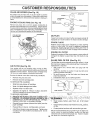
AIR SCREEN
ESPON
BILITIES
(See Fig. 19)
Air screen must be kept free of dirt and chaff to prevent
engine damage from overheating, Clean with a wire blush
or compressed air to remove dirt and stubborn dried gum
fibers
ENGINE
COOLING
FINS
(See
Fig. 19)
Remove any dust, dirt or oil from engine cooling fins to
prevent engine damage from overheating, Engine btower
housing must be removed. Remove side paneJs and hood
(See "TO REMOVE HOOD AND GRILL ASS EMBLY" in the
Service and Adjustments section of this manual).
FIG. 20
AIR SCREEN
COOLING FINS
(BOTH SIDES)
MUFFLER
Inspect and reptace corroded muffler and spark arrester (if
equipped) as it could create a fire hazard and/or damage
SPARK
PLUGS
Replace'spark plugs" at the _3eginning of e&ch mowing
season o_ after every "100 hours, of Op_r&tioCl, _h*ieheve]
come_, first., S'park plL_gtype and gap S&_tingar_ shown in
"PRODUCT SPECIFI(_ATIONS" on page'3 of tfiis manual_ =
ENGINE
OIL
FILTER
Replace the engine oil filter every season or every other oil
change if the tractor is used more than 100 hours in one
year',
IN-LINE
AIR FILTER
(See Fig. 20)
Your engine will not run properly using a dirty air' filter,
Clean the foampre-cteaner element after every 25 t_ours of
operation or every season, Service paper cartridge every
100 hours or every season, whichever occurs first
•
•
Service air cleaner more often under dusty conditions.
-
FUEL FILTER
(See Fig. 21)
The fuel filter should be rel_taced once each season If fuel
filter' becomes clogged, obstructing fuel flow to carburetor,
reptace .ment is required
With engine cool, remove filter and plug fuel line
sections
Remove wing nut and covert
=
Place new fuel filter in position in fuel line with arrow
pointing towards carburetor,
Be sure there are no Iuel line leaks and clamps are
properly positioned,
Immediately wipe up any spilled gasoline,
•
Remove seal and cartridge plate.
TO SERVICE PRE-CLEANER
•
Slide foam pre-cleaner off cartridge
•
Wash it in liquid detergent and water,.
•
Squeeze it dry in a clean cloth
-
Saturate it in engine oil Wrap it in clean, absorbent
Cloth ,.andsqueeze to remove excess oil
TO S ERVI.C.I_CA RTBtDGE
....
.
•
,
'
:.
.,
°
•
.
•
,
FIG. 21
"
.
. i.... .
.
.
,_- "l_',_lr_
:_:D_adt_._a,stT_._b_,',&t_e'r-'daffl_l.g_,'of: Lf,se-,;:,-':,iI_,,_.:.,_;_-N]'t_t_. t,,.:f, : _; :°¢:%%:,:., _., ::.:,:¢...,.:,r. ":,.:', ......
;" pre,ssunz.ed:.alr,.as, fhts'w_l-t'damag6,the
"c&rtrdge_ :,::
" : . : . ,- - ;,,. , '
: .
, : :
,':' • - . " . ,'
Replace a.dirty,' 1Sent,or darnaged ca_ri4ge
"
..
'..'
Cle_in engin.e, battery_ seat," fihish, etc of" all fbLeign : '•
Reinstall the pre-cteaner (cleaned _nd o ed)over the
paper cartridge,,
.
matter,
Keep finished surface s and wheeis free of all _asoiine,
oil, etc.
•
Protect painted surfaces with automotive type wax_
Reassemble air cleaner, cartridge plate, and seal
Install the air cleaner cover and wing nut Tighten wing
nut 1/2 turn to 1 full turn after nut contacts cover Do not
overtighten
18
We do not recommend using a garden hose to clean your
tractor unless the electrical system, muffler, air filter and
carburetor are covered to keep water out. Water in engine
can result in a shortened engine life.
SERVRCE AND ADJUSTMENTS
ii
,u,i
H, UHH,,,,,,,,,
CAUTION:
•
°o
In,
I ,U
n UU,
n,q
i1,
m,,,
n UI,,,,,,,,
In,HI
q,,,
TRACTOR
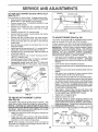
TO LEVEL MOWER
MOWER
n m U,U,H,U,,
(See Fig. 22)
Place attachment ctutch in "DISENGAGED" position
Turn height adjustment knob to lowest setting.
Lower mower to its lowest position
Remove retainer spring holding anti-swaybar to chassis bracket and d sengage ant -swaybar from bracket
:•
Remove retainer springs from suspension arms at
• deckhand d sengage arm€ _'roh_deqk.
°
Raise att'abhmeot lift to' i_s highest p,ositiOr_ " ',
Remove two retainer springs from e&ch front link and
remove links.
•
Slide mower forward and remove belt from electric
clutch pulley
•
Slide mower out from under right side of tractor.
IMPORTANT: IF AN ATTACHMENT OTHER THAN THE
MOWER DECK _STO BE MOUNTED ON THE TRACTOR,
REMOVE THE FRONT LINKS
HOUSING
Raise mower to its highest position.
Measure height from bottom of deck curl to ground
levei at front corners i)f mo_ver.'. Distance "A" on both
- sides ()[ _ower shbuld be the sameo:
i.
_' tf adjustment is ne_essary,make
adjustnqent on one
side of mower dnly.
•
To raise one side of mower, tighten lift link adjustment
nut on that side.
•
°
To lower one side of mower, loosen lift link adjustment
nut on that side.
NOTE: Each full turn of adjustment nut will change mower
height about 3(16".
Recheck measurements after adjusting.
MOWER
Follow procedure described in "INSTALL MOWER AND
DRIVE BELT" in the Assembly section of this manual.
FRONT
SUSPENSION
BRACKET
ADJUSTMENT
SUSPENSION
ARMS
NUTS
LIFT
LINKS
FIG. 23
BRACKET
ELECTRIC
CLUTCH
PULLEY
CHASSIS
FRONT
SUSPENSION
BRACKET_
4
RETAINER
SPRING
BRACKET
/
ANTI-SWAY
BAR
II,lr
Adjust the mower while tractor is parked on level ground or
driveway
Make sure tires are properly inflated (See
"PRODUCT SPECIFICATIONS" on page 3 of this manual),
If tires are over or underinfiated, you wii! not property adjust
your mower_,
SIDE-TO-SIDE ADJUSTMENT (See Fig& 22 and 23)
•
°
•
•
TO INSTALL
' .....................................
Place gearshift lever in neutral (N) position.
Depress
clutch/brake
pedal
fully and set parking
brake.
Place attachment
clutch
in "DISENGAGED"
position.
Turn ignition key "OFF" and remove key.
Make sure the blades and all moving parts have completely stopped.
Disconnect spark plug wire from spark plug and place wire where it cannot come in contact
with plug.
•
o
-
TO REMOVE
'U
BEFORE PERFORMING ANY SERVICE OR ADJUSTMENTS:
RETAINER
SPRINGS
\
FIG_ 22
19
j
iiii
lU
i
JlllUl,U
i
ii
SERVICE AN
ii nl
,1111,111111
u
TO REPLACE
FRONT-TO-BACK ADJUSTMENT (See Figs. 24 and 25) IMPORTANT: DECK MUST BE LEVELSIDE-TO-SIDE
tF
THE FOLLOWING FRONT-TO-BACK ADJUSTMENT IS
NECESSARY, BE SURE TO ADJUST BOTH FRONT LINKS
EQUALLY SO MOWER WILL STAY LEVEL SIDE-TO-SIDE
TO obtain the best cutting results, the mower housing
should be adjusted so the front is approximately 1/8" to 1/2"
lower' than the rear when the mower is in its highest
position
Check adjustment on right side of tractor
Measule distance "F" directly in front of and behind the mandrel at
bottom edge of mower' housing as shown,
•
Before making any necessary adjustments, check that
both front links are equal in length
•
If links are not equal in length, adjust one link to same
length as other link,
To lower fl'ont of mower housing, loosen nut"G" on both
front [inks an equal number of turns,
°
When distance "F" is 1/8" to t/2" lower at front than
rear, tighten nut"H" against trunnion on both front links,
•
To raise float of mower housing loosen nut' H_'from
ttunnior_ on both fr.oht link&..Tighten nut"'G_' 0h. both,
front finks an. equal'number of turns. :
.
When distance "F" js 178" to 1/2" 16wer'at'fz:on:t than
rear, tighten nut "H" against trunnion on both front
links.
NOTE: Each full turn of hut "G" will (}hange dim. "F; by
approximately 3/8",
o Recheck side-to-side adjustment
'
,:i
.
,UlllUl
ADJUSTMENTS
Jl
-. •
ilU ii
,,m
Ul
i i i
MOWER DRIVE
BELT
MOWER DRIVE BELT REMOVAL (See Fig. 26) •
•
Park tractor on a level surface.. Engage parking brake.
Remove four screws from LH mandrel cover and
remove covet.
•
Roll belt over the top of L H mandrel pulley.
,,
Remove belt from electric clutch pulley
o
Remove belt from idler pulleys.
.
Remove any dirt or grass clippings which may have
accumulated around mandrels and entire upper deck
surface.
•
Check primary idler arm and two idlers to see that they
rotate freely
•
Be sure spring is securely hooked to primary idler arm
and bolt in mower housing
MOWER DRIVE BELT INSTALLATION
(See Fig 26)-
•
Install bel.t in both idlers. Makesure
keepers afthe idlers as shown,_"
belt is in both belt
: . :
.; "
.
install new belt onto elec![icrclu}ch
"
R01l bblt.into upper groove of L,H,_mandrel puliey,
•
Carefully check belt routing rh,_king sure belt is in the
grooves correctly and inside belt keepers.
Reassemble LH mandrel cover.
•
MANDREL
SPRING
L,N.
MANDREL
CO';'ER"
;utle}/ '
ELECTRIC
CLUTCH
PULLEY
SCREWS
IDLER
PULLEYS
PRIMARY
I
FIG, 24
BOTHFRONTLtNKSSHOULO
BEEQUALINLENGTH
BOLT IN
MOWER
HOUSING
MANDREL
MOWER
DRIVE
BELT
\
BELT
KEEPERS
: t= G
FRONTLtNKS
FIG. 25
2O
\
!
SERVICE
TO REPLACE
(See Fig. 27)
MOWER
BLADE
AI
DRIVE
ADJUSTMENTS
BELT
CLUTCH PLATE
Park the tractor on level surface Engage parking brake
•
Remove mower drive belt (See'TO REPLACE MOWER
DRIVE BELT" in this section of this manual)..
•
Remove mower (See "TO REMOVE MOWER" in this
section of this manual)_
•
Remove four screws from RH. mandref cover and
remove cover. Unhook spring from bolt on mower
housing.
•
Carefully roll belt off RH.. mandrel pulley
•
Remove belt from center mandrel pulley, idier pulley,
and LH. mandrel pulley.
•
Remove any dirt or grass which may have accumulated around mandrels and entire upper deck surface
•
Check secondary idler alm and idler to see that they
rotate freely
•
Be sure spring is hooke d in secondary idler arm and
sway-bar bracket.
.
Install new belt io Ipwe[ groove of L H_. mandrel pulley,
idler;.pultey, and _center mandrel pelley asshow01
'Roll belt over t_;FI_.mandre! PUlle_j."Make su re be!t _sih"
all grooves properly.
•
Reconnect spring to bolt in mower housing and reinstall R,.H. mandrel cover
•
Reinstall mower to tractor (See"TO INSTALL MOWER"
in the Assembly section of this manual)..
•
Reassemble mower drive belt (See ''TO REPLACE
MOWER DRIVE BELT" in this section of this manual).
L,H.
MOWER BLADE
DRIVE BELT
NYLON LOGKNUT (3)
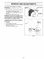
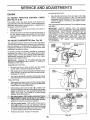
TO ADJUST
BRAKE
(See Fig. 29)
Your tractor is equipped with an adjustable brake system
which is mounted on the left side of the transaxle°
If tractor requires more than six (6) feet stopping distance
at high speed in highest gear, tt_en brake must be adjusted.
IMPO.RTANT: DO.NO'i _ O.VER TIGHTEN BRAKE.. W.HEN
DEPRESSING CLUTCH BRAKE. PEDAL,,THE MOTION
DRIVE.BELi" MUST STOP MOVrNG (DECLU.TCH FROM .
ENGINE'PULLE.Y)
BE.FORE BRAKE
EN_AGES..."
' IMPROPER ADJU'S'f:MENTW.I-LL CAUSE HARD SHI FTING
AND EXCESSIVE WEAR TO BRAKE LINING.
•
Park and turn off the tractor on a level surface. Place
gear shift lever in neutral IN) position
Disengage
parking brake and be sure tractor does not roll in either
direction°
CENTER
MANDREL
•
Lower mower deck (if installed on tractor)..
•
Snap out access hote cover o n left side of tractor above
footrest.
Loosen jam nut at clevis which will allow brake rod to be
rotated.
=
•
With pliers, from underside of frame, unscrew brake
rod trom clevis four (.4) to six (6) full turns.r
Start tractor with gear shift lever in neutral IN) pbsitien.
Slowly depress clutch/brake pedal to the point where
the motion drive belt stops moving. Hold clutch/brake
pedal in this position and engage parking brake° If belt
begins to move after engaging parking brake, reset
parking brake by depressing clutch/brake pedal slightly
to next notch on parking brake_
Stop engine. Screw brake rod back into clevis until
clevis pin is against rear edge of slot in brake arm. Do
not over tighten (see IMPORTANT" above).
Tighten jam nut against clevis..
Replace access hole cover.
°
•
SECONDARY
IDLER ARM
SPRING
\
•
SWAY-BAR
BRACKET
FIG. 27
•
•
CLUTCH
•
• : _"
/
.
The eleet_ric clutch shou+td provide yea.rs of service. The
qt.ut'ch.'h_as
.a b.uiit-m _rake that:sto'ps th.e' putiey .within 5
'.:trY_
2"c.aus'g,'therdewer;t_._._o-It_:eqga£1e_,,o_;,_0_ot_ep
:
'
'
Road test tractor for proper stopping distance and
declutching as stated abo_e. Readjust if necessary. If
proper adjustment canho.t b'e a.tta.iried, further'mainte"i'nan'.¢e ts:neoessaryo Gqntadt _our nearest auttiorized.
_,:_':..-_:. _.,- ,--:, _.._,:..
._,--*--.:_,,;:.
"a•_:'re_p,[ed 7"A_J_4_tbr;,_nts
st_'ouf.'d,
be'm.a_e 5_ y,our'nearest _:' ! i ' :. _:'"
"' "." '_: : °_""
_.uthorized serviEe center/department.
"
" "
_
. ._. ......
\_...
.
,Make sure attachment clutch and ignition switches are
CLEVIS _,,.,..,_u.
.__.
in"O position
"
•
;"-.
-." =:;':". : - ',.
*'.; :." " .'_":i.":."
.
":.:'_
P,.
Adjust the three nylon tocknuts until space between
clutch plate and rotor measures 012" at all three slot
locations cut in the inside of brake plate°
NOTE: After installing a new electric clutch, run tractor at
full throttle and engage and disengage electric clutch 10
cycles to wear in clutch plate
PLATE
FIG. 28
MANDREL
COVER
TO ADJUST ATTACHMENT
(SeeFi,',
28 \
BRAKE
_-, / I
_'_'_J I
BR_KE
ARM
21
/
CLEVIS
\
\
IL
I_
,-,>^
\\
BRAKE
"_
ROD
--
_¢-_,_
\O_.
"_-_%
FIG. 29
'_//_'_>_"
I _[1 _
)))
tOt_
--
(((
(O@_
SERVICE
,,,Ul,,
TO REPLACE
(See
MOTION
AND ADJUSTMENTS
,,,,,H,,,,HH,,
DRIVE
U
BELT
•
Engage parking brake (creates slack in belt).
•
Remove mower drive belt from electric clutch pulley
only (See "TO REPLACE MOWER DRIVE BELT" in
this section of this manual),.
•
Roll motion drive belt off transaxle pulley.
•
Roll belt off clutching idler pulleys, then off engine
pulley and front V-idler pulley.
.
Place V part of belt into grooves on engine pulley and
front V-idtet, making sure to route belt inside ..ofbelt
keepe.._s..
•
ut belt coming.from V-i_iler aboye midspar_ belt keeRei:;
,
FRONT
Place belt around transaxle pulley, beginning at top.
V part of belt should engage transaxle pulley.
°
Place long lower section of belt through loop in midspan
belt keeper.
,
Check to be +sure be!t is on proper side _)f all belt
keepers
WHEEL
,,
,
J
ALIGNMENT
WHEEL TOE-IN
ADJUSTMENT
Front wheel toe-in is required for'proper'steering operation+
Toe-in was set at the factory and adjustment should not be
necessary. If parts in the front axle or steering mechanism
have been replaced or damaged, check toe-in and adjust
if necessary.
TO CHECK TOEqN (See Fig.. 3t) •
Position front wheels straight ahead
Measure distance between wheels at front and rear of
tires (dimepsions "A" and "B")..
,
Front dimension "A" sh.ould be 1/8" to 1/4" less than
rear dirhension "B".
"
,
TO ADJL)ST TOE4N (See. Figs° 31 and 32) ,:
:•' L:ooser_.jam nui'+sat adju_,trfierit slee_'es bn tie fed..
"
-
STEERING
,,,,H,HmH
If steering wheel crossbars are not horizontal (left to right)
when wheels are positioned straight forward, remove steering wheel and reassemble per'instructions in the Assembly
section of this manual.
•
Pull belt out of al! belt keepers.
BELT INSTALLATION -
then" onto clutching idler pu.lleys :as shown
Make sure V part of belt engages V-idler.
',"""11
TO ADJUST
Fig. 30)
Park the tractor on level surface Engage parking brake+
For ease of service there is a belt installation guide decal on
bottom of left footrest It is not necessary to remove mower+
BELT REMOVAL -
°
,H, "H ,"'H'
,
Adjust tie rod until dimensior_"A" is t/8" to 1/4" less than
dimension "B".
-
Tighten jam nuts secutety+
•
Reinstall mower drive .belt onto electric clutch pulley.
IMPORTANT: +CHtECKBRAKE AbJUSTMENT.
FRONT
OF TFIACTOR
VIEWED FROM L.H. SIDE OF TRACTOR
CLUTC:HING
IDLER
CLUTCHING
FLAT IDLER
FIG+ 31
BELT
tKEEPER
ADJUSTMENT
SLEEVES
BELT
KEEPER
AS VIEWED. FFiOM BOTTOM
P_LLEY'
_..
FRONT WHEEt.
FIG. 30
CAMBER
The front wheel camber is not adjustable on your tractor+ If
damage has occurred to affect the front wheel camber,
contact your nearest authorized service center/departmenL
22
nil ii,,
,, inl
,,,11,1
uu
n
SERVUCE AND ADJUSTMENTS
TO REMOVE
WHEEL
FOR
REPAIRS
FRONT WHEEL (See Fig° 33)
•
Block up axle securely
•
Remove axle cover, retaining ring and washersto allow
wheel removal
•
Repair tire and reassemble.
°
Replace washers and snap retaining ring securely in
axle groove.
•
Replace axle cover.,
WASHERS
O
LH.
PANEL
BOLT
RETAINING
RING _
AXLE
COVER
\
\
]
FIG. 33
,
i"
i
FIG_ 34
REAR WHEEL •
Block rear axle securely_
•
Remove five (5) hub bolts to allow wheel removal.
•
Repair tire and reassemble.
bolts securely.
TO START ENGINE
(See Fig. 34)
TO REPLACE
Replace and tighten hub
WITH A WEAK BATTERY
Raise hood°
-
Pull bulb holder out of the hole in the backside of the
gd]L
Replace bulb in holder and push bulb holder securely
back into the hole in the backside of the grill.
.
RELAYS
Check wiring, See electrical wiring diagram in Repair
Parts section of this manual°
TO REPLACE
FUSE
Replace with 30 amp automotive4ype phJg-in fuse
fuse holder is located behind the dash.
TO ATTACH .JUMPER CABLES • . G6nnect ea:cli'end oi the REI3 cable,to the P.OSITIV_
T1VE (-) tertfl_i_alof fu]lycharge_l battery., '
" '"
Connect the other end of the BLACK cable to a panet
bolt on the left side of the tractor, away from fuel tank
and battery,
TO REMOVE CABLES, REVERSE ORDER -
°
AND
Loose or damaged wiring may cause your tractor to run
poorly, stop running, or prevent it from starting
°
°
Close hood
INTERLOCKS
tf your battery is too weak to start the engine, it should be
recharged.
If "jumper cables" are used for emergency
starting, follow this procedure:
IMPORTANT: YOUR TRACTOR 1SEQUIPPED WITH A 12
VOLT NEGATIVE GROUNDED SYSTEM. THE OTHER
VEHICLE MUST ALSO BE A 12 VOLT NEGATIVE
GROUNDED SYSTEM. DO NOT USE YOUR TRACTOR
BATTERY TO START OTHER VEHICLES
.
BULB
-
°
CAUTION: Lead-acid batteries generate explosive gases. Keep sparks, flame
and smoking materials away from batteries.
Always wear eye protection
when around batteries.
HEADLIGHT
BLACK cabte first from chassis and fuNy charged
battery,
RED cable last from both batteries,
23
The
SERVICE
TO ADJUST ATTACHMENT
(See Fig. 35)
AI D ADJUSTMENTS
LIFT SPRING
ADJUSTMENT
o
White holding spring bushing with wrench, loosen jam
nut
°
Turn adjustment
bolt clockwise
to extend
reduce lift effort for heavier attachments°
•
Turn adjustment
tachments.
°
Retighten
bolt counterctockwise
jam nut against
spring
spring
SPRING
and
for lighter
at-
bushing
°J
FIG, 35
TO REMOVE HOOD AND GRII..L ASSEMBLY
(See Fig. 36)
°
ATTACHMENT
LIFT SPRING
JAM NUT
IMPORTANT:
DO NOT ADJUST FOR MAXIMUM SPRING
TENSION WHEN USING LIGHT ATTACHMENTS
SUCH
AS A MOWER.. ADJUST LIFT LEVER SPRING TO AID IN
LIFTING ATTACHMENT.
DO NOT OVERPOWER
SPRING.
WHEN REMOVING
ATTACHMENT,
ALWAYS
ADJUST
SPRING TENSION TO ITS LOWEST POSITION..
-, " Raise hood_
BUSHING
HEADLIGHT
WIRE
CONNECTbR
"
unsn',_[_'l_ea_Jligh_tw,i_r_Ce.nne_tbr_
=
Stand infront of tractor_ Grasp hood at sides, tilt lowaid
engine and lift off of tractor.
=
To replace, reverse above piocedure
FIG. 36
24
i
IIH H
SEFiVNCE AND ADJUSTMENTS
HI,
ACCELERATION
ENGINE
•
TO ADJUST THROTTLE
(See Fig. 37 & 38)
CONTROL
CABLE
The throttle control has been preset at the factory and
adjustment should not be necessary.. Check adjustment as
described below before loosening cable. If adjustment is
necessary, proceed as follows:
•
With engine not running, move throttle control lever to
fast ('_) position_
•
Check that speed control lever is against stop screw. If
it is not loosen casing clamp screw and pull throttle
cable until lever is against screw T ghten clamp screw
securely.
TO ADJUST
CARBURETOR
(See
Move throttle control lever from slow (,_) to fast (,€_)
position_ If engine hesitates or dies, turn idle mixture
screw out (counterclockwise) 1/8 turn. Repeat test and
continue to adjust, if necessary, until engine accelerates smoothly.
High speed stop is factory adjusted. Do not adjust-damage
may result.
IMPORTANT:
NEVER TAMPER WiTH THE ENGINE
GOVERNOR, WHICH IS FACTORY SET FOR PROPER
ENGINE SPEED.. OVERSPEEDING THE ENGINE ABOVE
THE FACTORY
HIGH SPEED SETTING CAN BE
DANGEROUS. IF YOU THINK THE ENGINE-GOVERNED
HIGH SPEED NEEDS ADJUSTING, CONTACT YOUR
NEAREST
AUTHORIZED
SERVICE
CENTER/
DEPARTMENT, WHICH HAS PROPER EQUIPMENT AND
EXPERIENCE
TO
MAKE
ANY
NECESSARY
ADJUSTMENTSo
Fig. 39)
The carburetor has been present at the factory and adjustrdent should not'benecessary. Howevel_, minor adjustment
m_y .be' required 'to ¢ompe_nsate fQr "diff_rer_cesin fuel,
tem_perature;.altitude .or lo'ad_ I.fthe' carburetor d(_es need'
adjustment, proceed _,s follows:
STOP 'S(_REW
THROTTLE
CONTROL
CABLE
SETTING -
, FIG. 37
•
Be sure you have a dean air fi_ter, and the throttle
• control cable is adjusted properly (see above).
•
With engine off turn idle fuel adjusting neeclle in (clockwise) closing it finger tight and then turn out (counterclockwise) 1 - 1/4 turns.
•
Turn main fuel adjusting needle in (clockwise) closing
finger tight and then turn out (counterclockwise) 1 turn_
STOP
SPEED
,CONTROL
LEVER
FINAL SETTING
-
SPEED CONTROL
[
In geni_ral, turning the adjusting needles in (clockwise)
decreases the supply of fue! to the engine giving a leaner
fuel/air mixture, Turning the adjusting needles out (counterclockwise) increases the supply of fuel to the engine
giving a richer fue!/air mixture°
IMPORTANT:
DAMAGE TO THE NEEDLES AND THE
SEATS IN CARBURETOR MAY"RESULT 1F'SCREW iS
TURNED IN TOO TIGHT
PRELIMINARY
TEST -
Start engine and allow to warm for five minutes, Make
final adjustments with engine running and shift!motion
control lever in neutral (N) position.
With throttle control
main fuel adjusting
beg!ns to die then
engine runs rough.
be!v_een those tw_
lever in fast ( ,_ ) position, turn
needle in (clockwise) until engine
turn out (counterclockwise) until
Turn needle to a .point. midway
pos!tibns. _
.
...
FIG. 38
adj_stlhg
screw in or bqt until _0rrect idle i_..attained.
°
•
Idle f.uel needte setting - With throttle control lever in
slow (,_) position, turn idle fuel adjusting needle in
(clockwise) until eng ne begins to die and then turn out
(counterclockwise) until engine runs rough..Turn needle
to a point midway between those two positions.
MAIN FUEL
ADJUSTING
NEEDLE
Recheck idle speed. Readjust if necessary
FIGo 39
25
*
STORAGE
,,,
,
Immediately prepare your tractor for storage at the end of
the season or if the tractor will not be used for 30 days or
more.
m,,,,,,,
,,,,,,
,,,r
,,,
,,,,m,,,
,t
-
Clean entire tractoi: (See "CLEAN ING" in the Customer
Responsibil!ties section of this manual ).
!nspect a.nd repZa&e belt,_, if necessary (see belt _e_
I_laee'rfient i6_tructlbns it';the Se'_iee and Adjustments
section of'this: ma.ndal):
Lubricate as shown in "theCustomer Responsibilities
section of this manual.
Be sure that all nuts, bolts and screws are securely
fastened, tnspect moving parts fordamage, breakage
and wear,. Replace if necessary_
-
Touch up all rusted or chipped paint surfaces; sand
lightly before painting,.
•
,,,,,,,
•
Drain the fuel tank.
°
Start the engine and let it run until the fuel lines and
carburetor are empty.
o
Never use engine or carburetor cleaner products in the
fuel tank or permanent damage'may occur'..
o,
Usef J"esh.fiJefne×t_season,_
; .
. ,
NOTE: ..Foei stabilizer is _n a6._eptable alte._ri&tive .id
rhi_imizing tt_e formation of fuel gLim deposits'}Jdri_gstorage, Ada stabilizer to gasolinein fuel tank' or storage
€ontaineL Always follow the mix ratio found on stabilizer
container. Run engine at least 10 minutes after adding
stabilizer to allow the stabilizer to reach the carburetor. Do
not drain the gas tank and carburetor if using fuel stabilizer'..
ENGINE
OIL
Drain oil (with engine warm) and replace with clean engine
oil,. (See "ENGINE" in the Customer' Responsibilities
section of this manual).
BATTERY
°
,,,,,,
IMPORTANT:
1T IS IMPORTANT TO PREVENT GUM
DEPOSITS FROM FORMING IN ESSENTIAL FUEL
SYSTEM PARTS SUCH AS CARBURETOR, FUEL FILTER,
FUEL HOSE, OR TANK DURING STORAGE.
ALSO,
EXPERIENCE INDICATES THAT ALCOHOL BLENDED
FUELS (CALLED GASOHOL OR USING ETHANOL OR
METHANOL) CAN ATTRACT MOISTURE WHICH LEADS
TO SEPARATION AND FORMATION OF ACIDS DURING
STORAGE.
ACIDIC GAS CAN DAMAGE THE FUEL
SYSTEM OF AN ENGINE WHILE IN STORAGE.
,,n
•
°
o.
m,i
FUEL SYSTEM
Remove mower from tractor for' winter storage.. When
mower is to be stored for a period of time, clean it thoroughly, remove all dirt, grease, leaves, etc.. Store in a
clean, dry afea1_
•_,.
,,,,,,,,,,,,
,,, ,,,
TRACTOR
°
,,
ENGINE
gasoline in the tank inside a building
where
fumesNever
may store
reach the
an tractor
open flame
CAUTION:
with
or' spark.
Allow the engine to cool
before storing in any enclosure.
nl
....,.,,,,,,,,,
Fully charge the battery for storage
After a periqcJ of time in. storage, battery ma_' require
"re&harging,
CYLINDERS
To help prevent corrosion and power leakage during
long periods of storage, battery cables should be
disconnected and battery cleaned thoroughly (see'TO
CLEAN BATTERY AND TERMINALS" in the Customer Responsibilities section of this manual).
After cleaning, leave cables disconnected and place
cables where they cannot come in contact with battery
terminals.
_°
Remove Spark Plug(s).,
°
Pour one ounce of oil through spark plug hole(s) into
cylinder(s).
•
Turn ignition key to"START" position for a few seconds
to distribute oil
•
Replace with new spark plug(s).
OTHER
•
Be sure battery drain tube is securely attached.
-
Do not store gasoline from One season to another.
°
If battery is removed from tractor' for' storage, do not
store battery directly on concrete or damp surfaced.
°
Replace your gasoline can if your can starts to rust.
Rust and/or dirt in your gasoline will cause problems.
o.
If possib!e, stere your tractor' indoors and cover it to
g _ie p,rptectlon from dust and dirt:
•-.
Cover,y..our'_tractor.w,_tba._uttabl_p_t_oT.i.v:ecovel'.that_, . ..,
• " ": wit! cause _,_ourtr_Sto:r'tb,t@t. ""' ,:: "
. :
'IMPOF_TANT: NEVER COVER TRACTOR VVH)LE'i_NGINE
AND EXHAUST AREAS ARE STIL'L WARM
26
SERVICE
OTES
27
TROUBLESHOOTING
PROBLEM
Will
CAUSE
not start
to start
i
•
CORRECTION
1
Out of fueI
2
3
4
5
6
7
Engine not 'CHOKED
Engine flooded
Bad spark plug
Dirty air feller
D_rty fuel filler
Water Jn fuel
8
9
10
Hard
1
Fdl fuel tank
properly
2
3
4
5
6
7
See "TO START ENGINE' in Operation section
Wad several r'n_nutes before attempling to start
Replace spark plug
Cleanheplace a_r filter
Replace fuel filler
Dr.-'dn fuel tank and carburetor reNI tank with fresh
Loose or damaged wrong
Carburelor out of adlustment
Engtrre valves out of adjustment
8
9
I0
1
2
3
4
5
6-
Dtr[y air filter
Bad spark plug
Weak or dead batlery
Oirty fuel Nter
.
Stale Or dirty fuel
Loose dr dam#god wm_.g
7
Carburetor our of adjustment
.Engi_e'_alves otJt'qf a_jugtmgnt
i
Engine
Engine
stai't
wdl
not turn
over
clicks but will not
Loss of power
-"
5
6
7
8
9
•
""
gasotine and replace fuel Nter
Check all wiring
Contact an aulhonzed service center/department
Contact an authonzed service center/department
Cteanfreplace atr filter
Replace spark plug
Recharge or replace battery
Replace fuel filler
Dram fbel tank and refill w_lh fresh gasoline
Check all widng
"" "
C'ontacl an aulhor[_".e_tservi&e c.enter/depa.rtme_.
Contact an autRbnzed service richter/department
"
,;
"r
Corroded batlery lerm_nals
Loose or damaged w, rtng
Faulty ignition switch
Faulty solenoid or stader
Faulty operator presence sw_teh(es)
1
2
3
4
5
6
7
8
9
Depress clutchlbrake pedal
D_sengage attachment clutch
Recl_arge or replace battery
Replace fuse
Clean battery lerminafs
Check all wiring
Check/replace ignition sw_lch
Check!replace solenoid or starter
Contact an authorized service center/department
1
2
3
4
Weak or dead battery.
Corroded battery terminals
Loose" or damaged wlnng
Fad@ solenoid or starter
1
2:
3
,I
Recharge or replace battery
Clear'rbattery terminals
Check all wiring
Check/replace soleno_d or starter
1
2
3
4
5
6
7
8
9
Cutttng loo much grass!loo fast
Throttle tn "CHOKE' pos_ben
Budd-up of grass, leaves and trash unuer mower
Dirty air filter
Low oil level/dirty ell
Faulty spark plug
Dirty fuel filter
Stale or dirty fuel
Water to fuel
1
2
3
4
5
6
7
8
9
10
11
Set _n "H_gher Cut" position/reduce
speed
Adlust throttle control
Clean underside of mower hou-_mg
Clean/replace all Nter
Check oil teve!/change o_1
Ctean and regap or change spark plug
Replace fuel filter
Drain fuel tank and refill with fresh gasoline
Drain fuel tank and carburetor, refill tank with fresh
gasoline and replace fuel filter
Connect and tighten spark plug wire
Clean eng_ne,a_r screen/fins
12
Cteaet-reptace mufflcr
Spark plug wire loose
Dirty engineair
screen/fins.
D,_y/clOgdged.rrtulfler
'
-
-
_
12
L
!
2
3
4
5
6
7..
8
•
Clutch/brake pedal not depressed
Attachm4nt clutch is engaged
Weak or dead battery
B_own fuse
1.
tS_
-
vibration
"
i
:i
2
3
4
10
Excessive
POINTS
_r_ff_
:"
i
1
2
3
,.,'alves odt .oT.adlustmen_
.
o
.
"
.
"l
"'
,
Worn befit or loose blade
Bent blade mandrel
Loose!damaged pad(s)
HH
I
YS. "i3on't_ctan
..
.
.
1
2
3
28
a_ti4oriz_:se_ic'ec_'ritei.J"de##,R'_,nt"
..
:
"..::
Replace blade • T_gh'_enblade bolt
Replace blade mandrel
T_ghten loose part(s) Replace damaged parts
:'"
•
TROUBLESHOOTING
PROBLEM
CORRECTION
CAUSE
Engine eont}nues to run
when operator [eaves seat
with attachment clutch
1
POINTS
Fauttyoperator-safety presence control system
1
Check wking, switches and connections
If nol
corrected, contact an authorized service censer/
department
engaged
Poor
CUt
- unevee
Mower blades
rotate
will not
1
2
Worn. bent or loose blade
Mower deck not tevel
1
2
Replace blade Tighten blade bo[t
Lever mower deck
3
4
Buildup of grass, leaves, and trash under mower
Bent blade mandrel
5
Clogged mower deck vent holes from buildup of
grass, leaves, and trash around mandrels
3
4
5
Clean underside of mower housing
Replace blade mandre_
Clean around mandreIs to open vent holes
1
Obstructio_l in clutch mechanism
2
3
4
Worn/damaged mower drive belt
Frozen idler pulley
Frozen blade mandrel
1
2
3
4
Remove
Replace
Replace
Replace
obstruction
mower drive belt
idler pultey
blade mandrel
•
P our gi;as,s' discharge
_
I_-leadlight(s) not Working
(if so equ_ped)
Battery will not charge
Engine "backfires"
when turning engine
"OFF"
2
,:
E0gi,ne sp.eed top,sJd'_:
Travel speed t_o"fast "
:
'
3
4
Wet grass
Mower deck riot level
5.
6
7
8
Low/uneven tire air pressure
Worn, bent or loose blade
Buildup of grass, leaves and trash under mower
Mower drive belt worn
9
t0
11
Blades improperly installed
Improper blades used
Clogged mower deck vent holes from buildup of
grass, leaves, and trash around mandrels
I"
2
3
:4
5
6
7
8,
9
10
11r
1
Pt&ce throttle control in "FAS]_" pdsition
:
Shift t5 slower speed.
Allow grass to dry before mowing
Level mower deck..
Check tires Ior prol)er air pressure
Replace/sharpen btade Tighten blade bolt
Clean underside of mower housing
Replace mowerdrive
belt,
Reinsta_f blades sharp edge down
Replace with blades listed in this manual
Clean around mandrels to open vent holes
Turn swiLch "ON"
1.
_2
3
Switch is "OFF
Bulb, s) burned out
Faulty light s_itch'_
2:
4
5
Loose or Ltamaged wfdng
Blown fuse
4
5
R_,pia_e'bulb(s)
Chec_[eplac6
tigl_tswitch
,Check wiring and cohne_tions
Replace fuse
t
2
Bad battery ceil(s)
Poor cable conneclions
1
2
Replace battery.
Check/clean all connections
3
4.
Faul_ regulator (if so equipped)
Faulty alternator
3
4
Replace regulator
Replace alternator
Engine throt_Iecontrol not set at "SLOW"
position for 30 seconds before stopping engine
29
Move throttle control to "SLOW" position and allow
to idle for 30 seconds before stopping engine
t
-
30