1
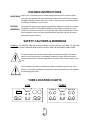
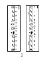
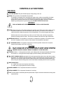
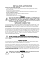
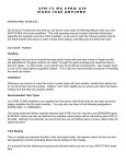
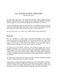
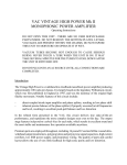
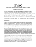
MODEL 2150 & CLASSIC
POWER A MPLIFIERS
USER’S M ANUAL
PACKING INSTRUCTIONS
UNPACKING Inspect your 2150/Classic amp for hidden damage that may have occurred in transit.
Your amp was inspected and sound-tested before shipment from the factory. All claims
for shipping damage must be made by the receiver. Save your box and packing material
for evidence of damage if it has occurred.
The original box and packing materials are specifically designed to protect your amp durPACKING
MATERIALS ing shipment. SAVE ALL PACKING MATERIALS. In the unlikely event that your amp
needs to be returned to the factory, the original box and packing materials will be necessary for shipment. These are carrier-approved packing materials, and they will ensure
safe transit back to the factory.
SAFETY CAUTIONS & WARNINGS
WARNING: TO PREVENT FIRE OR SHOCK HAZARD, DO NOT EXPOSE THIS UNIT TO RAIN OR
MOISTURE. DO NOT OPERATE NEAR WATER. ALWAYS USE THE PROVIDED POWER CORD.
The lightning flash with arrowhead symbol within an equilateral triangle is intended to
alert the user to the presence of uninsulated “dangerous voltage” within the product’s
enclosure that may be of sufficient magnitude to constitute a risk of electric shock to persons.
The exclamation point within an equilateral triangle is intended to alert the user to the
presence of important operating and maintenance (servicing) instructions in the literature
accompanying the product.
TUBE LOCATION CHARTS
2150
CLASSIC
6CA7/EL34
6CA7/EL34
12AT7
KT88/6550A
12AX7A
12AT7
KT88/6550A
6CA7/EL34
1
12AX7A
6CA7/EL34
2150/CL ASSIC
OWNER’S MANUAL
ongratulations. You have purchased unquestionably the finest musical instrument
power amplifier available.
C
Your new VHT power amplifier incorporates a unique combination of state-of-the-art
electronics and time-honored audio design. Meticulous craftsmanship coupled with only
the highest-quality components assures decades of trouble-free performance.
Before power-up, please take a few moments to familiarize yourself with this manual
and discover the impressive features and flexibility of the 2150 and Classic power
amplifiers. You will also find out how you can achieve maximum performance from your
VHT with a minimum of basic maintenance and operational information.
As always, please observe normal safety precautions when operating this equipment
and pay particular attention to the caution and warning designations in this manual and
on the amplifier chassis. These simple precautions are intended to ensure the extended
useful life of the equipment and, more important, of the operator.
Serial Number:
_____________________________
Date of Purchase: _____________________________
Dealer Name:
_____________________________
Dealer Address:
_____________________________
1200 Lawrence Drive
Suite 465
Newbury Park, California 91320
(805) 376-9899
2
SPECIFICATIONS
2150
Power Output:
Input Impedance:
Input Sensitivity:
Output Impedance:
Power Requirements:
Dimensions:
Front-Panel Features:
Rear-Panel Features:
105 watts RMS per channel
100 watts per channel, both driven simultaneously
Four KT88/6550A output tubes, two per channel
Two 12AT7 driver tubes, one per channel
Two 12AX7 preamp tubes, one per channel
100k ohm
Switchable -10dBV to 0dBV
Selectable to 4, 8, and 16 ohms
117 Volts AC, 60 Hz, 6 amps max, 700 watts max
Height, 7" (4 rack spaces), Width, 19", Depth, 12",
Weight, 53 lbs
Power switch, mains fuse, DC fuse for each channel, presence control for each
channel, depth (variable damping) control for each channel, standby switch for
each channel, fan speed switch
AC input, impedance selector for each channel, parallel output jacks for each
channel, voicing switch for each channel, input jacks, input sensitivity switch
CLASSIC
Power Output:
Input Impedance:
Input Sensitivity:
Output Impedance:
Power Requirements:
Dimensions:
Front-Panel Features:
Rear-Panel Features:
120 watts RMS per channel
105 watts per channel, both driven simultaneously
Eight 6CA7/EL34 output tubes, four per channel
Two 12AT7 driver tubes, one per channel
Two 12AX7 preamp tubes, one per channel
100k ohm
Switchable -10dBV to 0dBV
Selectable to 4, 8, and 16 ohms
117 Volts AC, 60 Hz, 6 amps max, 700 watts max
Height, 7" (4 rack spaces), Width, 19", Depth, 12",
Weight, 56 lbs
Power switch, mains fuse, DC fuse for each channel, volume control for each
channel, presence control for each channel, depth (variable damping) control for
each channel, standby switch for each channel, fan speed switch, combination
standby/half-power switch for each channel
AC input, impedance selector for each channel, parallel output jacks for each
channel, voicing switch for each channel, mode switch for each channel, input
jacks, input sensitivity switch
Because we strive to build the highest quality products, we reserve the right to change specifications of our
products without prior notice.
3
CONTENTS
PACKING & UNPACKING INSTRUCTIONS
Safety cautions and warnings
Tube location charts
INTRODUCTION
SPECIFICATIONS FOR 2150 & CLASSIC
FRONT-PANEL CONTROLS & FUNCTIONS
Standby switch
Volume control
Presence control
Depth control
Fan speed switch
A fuse and B fuse
Mains (AC power) switch
Mains (AC power) fuse
Fuse replacement information
Definition of damping
REAR-PANEL CONTROLS & FUNCTIONS
Voltage rating indicator
Mains (AC power) receptacle for power cord
Mode switch for pentode/triode operation
Impedance selector switch
Speaker outputs
Voicing switch
Inputs (A/Mono input and B input operation)
Input sensitivity switch
Model number plate
Serial number plate
Fan location and operation
INSTALLATION & OPERATION
SPEAKER CONNECTION
Setting proper impedance
VENTILATION
MAINTENANCE & SERVICE
General precautions
Tube replacement
TROUBLESHOOTING GUIDE
CONNECTING TO A GUITAR AMPLIFIER
Design for building a simple load box/output pad
CONNECTING THE 2150/CLASSIC
Slaving heads equipped with line-level output
Slaving heads not equipped with line-level output
Preamp configurations
WARRANTY INFORMATION
4
1
2
3
5
7
9
9
9
10
11
11
12
13
14
15
CONTROLS & FUNCTIONS
FRONT PANEL
1 STANDBY: Disconnects power to individual channels when idling.
2150:
I = on
0 = standby
CLASSIC:
I = half power
0 = standby
II = full power
After turning the power on, wait a few minutes before turning the standby on. In this way, you can warm up the
amplifier before applying full voltage to the tubes. This helps the tubes and other components to last longer. Tube
life will also be extended if, during breaks, the standby switch is used to turn the amplifier off instead of the power
switch. This keeps the tubes at a stable temperature and maintains the amplifier in a constant state of readiness.
2 VOLUME: Normal setting for best signal-to-noise ratio is between 12 o’clock and 2 o’clock.
3 PRESENCE: High-frequency boost/cut. The higher the frequency, the more active this control appears to be.
4 DEPTH: Variable damping control. The lower the frequency, the more active this control appears to be.
A WORD ABOUT DAMPING. Damping is a function of audio amplifier design that controls or inhibits speaker-cone
excursion at low frequencies. Turning the Depth control clockwise decreases the amp’s damping factor and thereby
increases the apparent low-frequency response of the amp/speaker system. This effect is more pronounced at higher volume settings. Different speaker systems also cause this function to behave differently. Experiment!
5 FAN SPEED: Adjusts cooling rate. Set to “Hi” for most playing situations. The “S” symbol on the switch is the
position indicator.
6
9 A FUSE, B FUSE: These are 1-amp “normal-blo” fuses. They are the individual DC power supply and
output protection fuses for channel A and channel B. *NOTE: The 2150 uses flameproof fuses.
CAUTION
TO REDUCE RISK OF FIRE, REPLACE ONLY WITH THE SAME TYPE FUSE. DISCONNECT
POWER BEFORE CHANGING THE FUSE.
7 MAINS: This is the primary AC power switch for both channels and the fan; “I” = on, “0” = off.
8 MAINS FUSE: This is a 10-amp “slo-blo” type fuse. It is the primary AC protection fuse for both channels
and the fan.
5
1
VOLUME
2
PRESENCE
3
DEPTH
4
2150
STANDBY
2
PRESENCE
3
DEPTH
4
CHANNEL A
1
VOLUME
CLASSIC
STANDBY
CHANNEL A
5
HI
5
HI
FAN
B FUSE
1A
FAN
B FUSE
1A
LO
6
6
LO
7
MAINS
7
MAINS
8
8
MAINS FUSE
10 A S.B.
A FUSE
1A
9
9
MAINS FUSE
10 A S.B.
A FUSE
1A
2
PRESENCE
3
DEPTH
4
STANDBY
1
2
PRESENCE
3
DEPTH
4
STANDBY
1
CHANNEL B
VOLUME
*
VOLUME
CHANNEL B
6
*
CONTROLS & FUNCTIONS
REAR PANEL
1 VOLTAGE RATING: This plate indicates proper voltage rating of the unit.
2 MAINS: AC input socket. See Installation & Operation.
This amplifier is equipped with a grounding-type supply cord to reduce the possibility of leakage
current. Be sure to connect it to a grounded receptacle. Operation from an ungrounded (twopronged) AC receptacle requires a 3-to-2-contact grounding-type adapter. Be sure to connect the
adapter’s grounding lead to a good earth ground. DO NOT ALTER THE AC PLUG.
WARNING
FOR CONTINUED SAFE OPERATION, USE ONLY THE AC CORD PROVIDED.
3 MODE (Classic series only): This switch changes the operation of the EL34 output tubes, which use five
components inside each tube. With this switch in the up position, the tubes run in the Pentode
mode, and all five components operate for full 100-watt power. The sound is brighter and crisper.
With the switch in the down position, the tubes run in the Triode mode, and three components
operate for 50-watt maximum power. The sound is smoother with a little less edge. Experiment!
4 IMPEDANCE SELECT: The impedance of a speaker or combination of speakers must equal the value
set on the “Impedance Select” switch for each channel. See Installation & Operation.
5
6
SPEAKER OUTPUT: The speaker output jacks are wired in parallel. Channel will not operate
unless the jack labeled “Use First” is used first!
CAUTION
DO NOT OPERATE UNIT UNLESS THE SPEAKER (OR OTHER CORRECT IMPEDANCE
LOAD) IS CONNECTED TO THE SPEAKER OUTPUT JACK(S). FAILURE TO USE THE
PROPER SPEAKER LOAD MAY RESULT IN DAMAGE TO THE AMPLIFIER.
7 VOICING: Position “1” voicing produces smooth, open midrange with soft highs and slightly rolled off low
end. Position “2” voicing produces sharper highs, punchier midrange, and beefier low end.
8
10 INPUT A/ MONO AND B: Input signal is fed to the input sensitivity switch, then to the volume control.
Signal fed to the “A/MONO” input automatically “normals” (connects directly) to the B input when the B
input jack is not connected. (Both channels’ outputs must still be connected to separate speaker systems.) If only one channel is being used, set the unused channel’s standby switch to the off (“0”) position.
9 INPUT SENSITIVITY:
Hi = -10dB This is the most frequently used setting.
Lo = 0dB Use for high signal levels such as “slaving.”
11 MODEL NUMBER: This is important information for reference.
12 SERIAL NUMBER: This is important information for servicing.
13 FAN: The fan’s speed is controlled by the front-panel switch. Keep the area around the fan and cooling vents
clear at all times.
7
SPEAKER
VOICING
1
2
7
B
8
INPUT
HI
LO
SENSITIVITY
9
A / MONO
10
VOICING
1
2
7
13
SPEAKER
USE FIRST
5
OUTPUT
6
IMPEDANCE
8
4
SELECT
16
6
OUTPUT
USE FIRST
5
MODE
PENTODE
TRIODE
3
MODEL
SERIAL
11 12
8
IMPEDANCE
8
SELECT
4
4
MODE
PENTODE
TRIODE
3
16
2
VAC
50 / 60 Hz
700 WATTS
1
4
INSTALLATION & OPERATION
BEFORE APPLYING POWER, MAKE SURE:
1. Unit is connected to the correct voltage source with a proper 3-wire grounded outlet. Use only
the AC cord provided.
2. Cooling vents are free from obstruction.
3. Speakers are plugged into the correct output jacks using minimum 18-gauge speaker cable.
DO NOT USE SHIELDED CABLE.
4. Impedance selector is at correct setting. See Speaker Connection.
5. Fan speed switch is set at “Hi.”
6. Standby switches are set to off (“0”) position.
CAUTION
DUE TO THE HIGH POWER OUTPUT OF THIS EQUIPMENT, IT IS IMPORTANT TO BE
AWARE THAT ELECTRICAL SAFETY AS WELL AS SONIC QUALITY CAN BE SEVERELY COMPROMISED BY THE USE OF SUBSTANDARD OR UNDERRATED AC POWER
SOURCES. DO NOT USE UNGROUNDED OUTLETS, MULTIPLE OUTLETS AND/OR
EXTENSION CORDS SMALLER THAN 18 GAUGE.
SPEAKER CONNECTION
It is extremely important to select the proper impedance setting for the speaker system(s) used. This setting is determined separately for each channel; that is, one 16-ohm speaker in channel A = selector setting “16”; one 8-ohm or two 16-ohm cabinets = selector setting “8”; one 4-ohm or two 8-ohm cabinets =
selector setting “4.”
Some manufacturers represent impedance mismatching as an optional tone-modifying technique. Due to
the extremely high power output and dynamic range of the 2150, we strongly advise against this practice.
The one exception to this rule applies to the operation of the Classic series in the low-power setting. In
this case, with the Standby switch set at half-power (“I”), the “Impedance Select” settings are divided by
two for a correct match; i.e., setting “16” = 8 ohms; “8” = 4 ohms, etc. Observing this correction will
ensure proper speaker/amplifier interaction.
CAUTION
FAILURE TO OBSERVE PROPER IMPEDANCE SETTING MAY SIGNIFICANTLY SHORTEN TUBE LIFE AND/OR CAUSE SEVERE DAMAGE TO THE AMPLIFIER. DAMAGE
RESULTING FROM IMPROPER SPEAKER INTERFACE IS NOT COVERED UNDER WARRANTY.
VENTILATION
The cooling system in the 2150/Classic is designed to draw heat out of the enclosure and provide the
maximum amount of cooling for the power dissipated in an enclosed space.
Occasionally, when recording or performing in a quiet environment, fan noise may be a problem. Under
these circumstances, the “Lo” fan speed may be used. To set the fan to “Lo,” gently insert the proper-size
screwdriver into the switch slot and rotate the switch to the left (counterclockwise) until a click is heard.
Turning the switch in the wrong direction or attempting to force the switch past its detent point may cause
permanent damage to the switch. Return the fan switch’s setting to the “Hi” speed position once normal
or high-volume operation has resumed.
CAUTION
OPERATION OF THE AMPLIFIER AT HIGH VOLUME SETTINGS WITH THE FAN SET AT
“LO” MAY RESULT IN SEVERELY SHORTENED TUBE LIFE.
9
MAINTENANCE & SERVICE
Proper maintenance and routine servicing will assure continued top-notch performance from your VHT
Amplification system.
Generally, we prefer that routine service and tube replacement are performed by your VHT dealer or service outlet.
WARNING: HOT TUBES! HAZARDOUS VOLTAGES!
1. Always remove the power cord before attempting tube or fuse replacement.
2. Wait at least 5 minutes before attempting tube or fuse replacement, to allow time for tubes to cool and
hazardous voltages to drain off.
3. When replacing tubes, remove only the rear cover.
4. Tubes: The 2150 tube complement consists of four VHT Special Design KT88/6550As, two 12AX7s,
and two 12AT7s. The Classic tube complement consists of eight VHT Special Design 6CA7/EL34s, two
12AX7s, and two 12AT7s. VHT Special Design electronic tubes provide optimum performance in this
amplifier. For best results, only replace with VHT original equipment tubes.
CAUTION
THE FAN CORD MUST BE DISCONNECTED BEFORE THE COVER CAN BE COMPLETELY REMOVED. THIS IS ACCOMPLISHED BY SIMPLY REMOVING THE FAN PLUG AT
THE TOP OF THE FAN. CARE MUST BE TAKEN TO PREVENT STRAIN ON THE FAN
CORD WHEN REPLACING THE COVER.
5. Gently rotate tubes out of their sockets so as to avoid stress on the contacts and possible tube breakage.
6. Note tube pin orientation so as to facilitate correct replacement of the tube in its socket. NEVER
FORCE A TUBE INTO ITS SOCKET.
7. When replacing fuses, gently push the fuse post in and turn slightly to the left with the proper-size
screwdriver. Then gradually release pressure to avoid stripping or fuse holder breakage.
WARNING!
TO REDUCE RISK OF FIRE, REPLACE ONLY WITH THE SAME TYPE OF FUSE.
IMPORTANT: REFER ALL OTHER SERVICE AND MAINTENANCE OPERATIONS TO QUALIFIED
SERVICE PERSONNEL. THERE ARE NO USER-SERVICEABLE PARTS INSIDE. TO AVOID RISK OF
SHOCK, DO NOT REMOVE THE BOTTOM OR TOP COVERS.
10
TROUBLESHOOTING GUIDE
WON’T TURN ON
1. Make sure AC cord is securely connected at both ends.
2. Verify the power source with something you know works.
3. Check the mains fuse, and replace if necessary (if it blows again, refer to qualified service personnel).
NO SOUND
(One or both channels):
1. Check volume controls.
2. Make sure that the input sensitivity switch is in the proper position.
3. Check the standby switch.
4. Check input cables.
5. Make sure that the mode switch is fully engaged in either pentode or triode mode.
6. Check speaker cables to see if they are disconnected or shorted.
7. Make sure that the impedance selector is fully engaged in its detent.
8. Check for blown speakers.
9. If a channel’s fuse is blown, replace with a 1A fast-blo (if it blows again, refer to qualified service personnel).
RUNNING HOT
1. Set the fan speed to “Hi.”
2. Make sure that the unit has adequate ventilation.
3. Make sure that the fan cord is securely connected.
4. The tubes may be under-biased (refer to qualified service personnel).
DISTORTION
1. Check the speakers.
2. Check the cables. See Installation & Operation
3. Check the impedance setting.
4. Check the signal level at other devices in the signal path.
5. The tubes may be over-biased (refer to qualified service personnel).
CONNECTING TO A GUITAR AMPLIFIER
ver wonder what that treasured old tweed Deluxe would sound like as a 200-watt powerhouse?
Here’s a simple load box/output pad configuration that will allow you to drag all your favorite antiques
out of the closet and really go for a spin. Just connect the speaker output from your source amplifier to
the input of this load box, and then connect the variable line output of the load box to the A/Mono input of
your 2150 or Classic.
E
Input
(J1)
R2
S1*
R3
VR1
Variable
Line
Output
(J2)
R1**
PARTS LIST
J1, J2
S1
R1
R2
R3
VR1
*
S1 must be closed when no speaker
is connected to amplifier.
** R1’s value will be determined by the
source amplifier’s impedance rating.
Mono 1/4" phone jack
SPST (single-pole/single-throw) heavy-duty toggle switch
4, 8, or 16 ohm, 100-watt resistor (Dale NH 100 or equivalent)
2,200 ohm, 1/2-watt resistor
470 ohm, 1/2-watt resistor
10k ohm audio-taper potentiometer
11
CONNECTING THE 2150/CLASSIC
SLAVING HEADS EQUIPPED WITH LINE-LEVEL OUTPUT
Speaker
Output
Line
Output
Head
Speaker
Output
Speaker
Speaker
Output
A/Mono
Input
Speaker or
Dummy Load
Speaker
Speaker
Speaker
Speaker
Output
2150 or Classic
Power amp
Line
Output
Speaker
Head
Effects switcher,
Mixer, etc.
Right
Output
Speaker
Speaker or
Dummy Load
Left
Output
Speaker
Output
Speaker
Output
B
Input
2150 or Classic
Power amp
A
Input
Speaker
Speaker
Speaker
Speaker
12
CONNECTING THE 2150/CLASSIC
SLAVING HEADS NOT EQUIPPED WITH LINE-LEVEL OUTPUT
Speaker
Outputs
Head
Output
Pad*
Effects devices,
Switcher, etc.
Speaker
Speaker
Left output
Right output
2150 or Classic
Power amp
B
Input
A
Input
Speaker
Speaker
Speaker
Speaker
* See Connecting To A
Guitar Amplifier, page 11.
Speaker
Outputs
Speaker
Output
Head
Head
2150 or Classic
Power amp
Speaker
Output
Speaker
Speaker
Simulator
Speaker
Output
Effects
A/Mono
Input
Speaker
Speaker
Output
Speaker
Speaker
Output
Speaker
B
A
Input Input
Speaker
Speaker
Note: In this configuration, the input level switch
on the power amplifier is a sufficient pad when connecting directly to a speaker output. The input sensitivity switch must be set to “Lo.” Do not insert signal-processing devices between the head and power
amp in this setup.
Speaker
Speaker
13
Speaker
Speaker
2150 or Classic
Power amp
CONNECTING THE 2150/CLASSIC
PREAMP CONFIGURATIONS
Mono preamp connected
directly to power amp
Stereo preamp connected
directly to power amp
Preamp
Preamp
Preamp
Output
Speaker
Output
Preamp
Outputs
Speaker
Output
Speaker
Output
2150 or Classic
Power amp
A/Mono
Input
Speaker
2150 or Classic
Power amp
B
A
Input Input
Speaker
Speaker
Speaker
Output
Speaker
Speaker
Mono preamp’s output
sent in series through
effects to power amp
Preamp
Speaker
Speaker
Speaker
Stereo preamp with
effects in parallel
Preamp
Stereo
Delay/chorus
Line
Outputs
Effects
Loop
R
Reverb
Compressor
R
R
Mixer
L
Switcher
R
L
Aux. sends
1 2
Channels
Reverb
R
R
Compressor
Stereo
Delay/chorus
L
L
3 4 5 6
Channels
L
Outputs
Speaker
Output
Speaker
Output
2150 or Classic
Power amp
R
Speaker
Output
B
A
Input Input
Speaker
Speaker
L
Speaker
Output
2150 or Classic
Power amp
A
B
Input Input
Speaker
Speaker
Speaker
Speaker
14
Speaker
Speaker
L
WARRANTY
Subject to the Obligations and Exclusions found below, this VHT product is warranted against manufacturing defects in materials and workmanship for the period of one (1) year from the date of purchase, with
the exception of the tubes and fuses, which carry a 90-day warranty.
The warranty period commences on the date of purchase by the original user. Performance under this
warranty must be obtained at one of the following: a VHT Authorized Service Station, by returning the
unit to the VHT factory with prior authorization, or (in countries outside of the United States) by a representative VHT distributor. A list of VHT Authorized Service Stations can be obtained from VHT, 1200
Lawrence Drive, Suite 465, Newbury Park, CA 91320, USA, Attn: Warranty Service. Telephone (805)
376-9899; Fax (805) 376-9999.
OBLIGATIONS
1. This warranty will be honored only on the presentation of the original proof of purchase.
2. Transportation of the product to and from an authorized VHT service outlet is the responsibility of the
user. Units sent directly to the VHT factory for warranty repairs must be authorized by VHT and shipped
prepaid.
EXCLUSIONS
1. This warranty shall not cover adjustment of customer-operated controls as explained in the appropriate
model’s instruction manual, or products that have been altered or have missing or defaced serial numbers.
2. This warranty shall not apply to the appearance of accessory items including, but not limited to, cabinets, cabinet parts, or knobs.
3. This warranty does not apply to uncrating, setup, installation, or the removal and reinstallation of products for repair.
4. This warranty shall not apply to repairs or replacements necessitated by any cause beyond the control
of VHT including, but not limited to, any malfunction, defects, or failure caused by or resulting from unauthorized service or parts, damaged or broken tubes, incorrect line voltage, improper maintenance, modification or repair by the user, abuse, misuse, neglect, accident, fire, flood, or other Acts of God.
5. Responsibility for the repair of any VHT product sold outside of U.S. boundaries is borne by the VHT
representative in that particular country or territory. Also, the warranty term and conditions may be different from those stated above. Please contact the VHT distributor or dealer in your country for more information.
The foregoing is in lieu of all other expressed warranties, and VHT does not authorize any party to
assume for it any other obligation or liability. In no event shall VHT be liable for special or consequential
damages arising from the use of this product, or for any delay in the performance of this warranty due to
causes beyond our control. Some states do not allow limitations on how long an implied warranty lasts
and/or do not allow the exclusion or limitation of consequential damages, so the above limitations on
implied warranty and consequential damages may not apply to you. This warranty gives you specific
legal rights. You may have other rights that vary from state to state.
15
1200 Lawrence Drive
Suite 465
Newbury Park, California 91320
(805) 376-9899