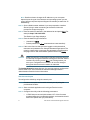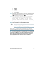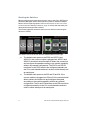
1
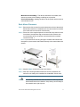
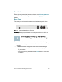
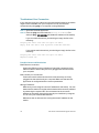
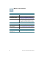
Quick Start Guide
500 Series Stackable Managed Switches
Welcome
Thank you for choosing the Cisco 500 Series Stackable Managed Switch,
a Cisco network communications device. This device is designed to be
operational right out of the box as a standard layer 2 and 3 switch. In the
factory default configuration, it will forward packets between connecting
devices after power up.
Before you begin installing the switch, make sure you have all of the
package contents available, access to the Cisco 500 Series Stackable
Managed Switch Administration Guide, and a PC with a web browser for
using web-based system management tools.
Package Contents
• Cisco 500 Series Switch
• Rackmount Kit
• Power Cord
• This Quick Start Guide
• Product CD
• Serial Cable
• Rubber Feet
This guide will familiarize you with the layout of the switch and describe
how to deploy the device in your network. For additional information, see
www.cisco.com/smb.
1
Mounting the Cisco Stackable Managed
Switch
There are two ways to physically install the switch:
• Set the switch on a flat surface.
• Mount the switch in a standard rack (1 rack unit).
Do not deploy the device in a location where any of the following
conditions exist:
High Ambient Temperature—The ambient temperature must not
exceed 104 degrees Fahrenheit (40 degrees Centigrade).
Reduced Air Flow—Both side panels must be unobstructed to prevent
overheating.
2
500 Series Stackable Managed Switches
Mechanical Overloading—The device should be level, stable, and
secure to prevent it from sliding or shifting out of position.
Circuit Overloading—Adding the device to the power outlet must not
overload that circuit.
Rack-Mount Placement
STEP 1 Remove the four screws from each side near the front of the switch.
Retain the screws for re-installation. (Do not remove the four screws
from each side near the back of the switch.)
STEP 2 Place one of the supplied spacers on the side of the switch so the
four holes of the spacers align to the screw holes. Place a rack
mount bracket next to the spacer and reinstall the four screws
removed in step 1.
NOTE If your screws are not long enough to reattach the bracket with
the spacer in place, attach the bracket directly to the case without the
spacer.
STEP 3 Repeat Step 2 for the other side of the switch.
STEP 4 After the mounting hardware has been securely attached, the
switch is now ready to be installed into a standard 19-inch rack.
CAUTION
For stability, load the rack from the bottom to the top, with the
heaviest devices on the bottom. A top-heavy rack is likely to
be unstable and might tip over.
500 Series Stackable Managed Switches
3
2
Connecting Network Devices
To connect the switch to the network:
STEP 1 Connect an Ethernet cable to an Ethernet port of a computer, printer,
network storage, or other network device.
STEP 2 Connect the other end of the network Ethernet cable to one of the
numbered switch Ethernet ports.
The Ethernet port light turns green when the connection is active.
Refer to External Features of the Cisco 500 Series Stackable
Managed Switch, page 12 for details about the different ports
and LEDs on each switch.
STEP 3 Repeat Step 1 and Step 2 for each device you want to connect to
the switch.
NOTE Cisco strongly recommends using Cat5 or better cable for Gigabit
connectivity. When you connect your network devices, do not exceed
the maximum cabling distance of 100 meters (328 feet). It can take up to
one minute for attached devices or the LAN to be operational after it is
connected. This is normal behavior.
NOTE 500 Series switches have both standard Ethernet and stack ports.
Standard ethernet ports can not be used for stacking. Refer to Stacking
the Switches, page 8 for additional details.
Power over Ethernet (PoE) Considerations
If your switch is one of the PoE models, as a PSE (Power Sourcing
Equipment) device, the switch supports 802.3at which can deliver up to 30
Watts per PoE port to a PD (Powered Device).
4
500 Series Stackable Managed Switches
Configuring the 500 Series Stackable
Managed Switch
3
Before You Begin
Verify the managing computer requirements in the product release notes.
The switch can be accessed and managed by two different methods; over
your IP network using the web-based interface, or by the Command Line
Interface (CLI) through the console port. Using the console port requires
advanced user skills.
Accessing and Managing Your Switch
Use the Web-Based Interface
To access the switch by using the web-based interface, you must know
the IP address the switch is using. The switch uses the factory default IP
address of 192.168.1.254 by default.
When the switch is using the factory default IP address, the System LED
flashes continuously. When the switch is using a DHCP server-assigned IP
address or an administrator has configured a static IP address, the System
LED is on solid (DHCP is enabled by default).
NOTE If you are managing the switch through a network connection and
the switch IP address is changed, either by a DHCP server or manually,
your access to the switch will be lost. You must enter the new IP address
the switch is using into your browser to use the web-based interface. If
you are managing the switch through a console port connection, the link
is retained.
To configure the switch through an IP network:
STEP 1 Power on the computer and the switch.
STEP 2 Set the IP configuration on your computer.
a.
If the switch is using the factory default IP address of
192.168.1.254, you must chose an IP address for the computer
in the range of 192.168.1.1-192.168.1.253 that is not already in
use.
b. If the IP addresses is assigned by a DHCP server, make sure
the DHCP server is running and can be reached from the
switch and the computer. It might be necessary to disconnect
and reconnect the devices for them to discover their new IP
addresses from the DHCP server.
500 Series Stackable Managed Switches
5
NOTE Details on how to change the IP address on your computer
depend upon the type of architecture and operating system you are
using. Use the computer Help and Support functionality to search for “IP
Addressing.”
STEP 3 Open a Web browser window. If you are prompted to install an
Active-X plug-in when connecting to the device, follow the
prompts to accept the plug-in.
STEP 4 Enter the switch IP address in the address bar and press Enter. For
example, http://192.168.1.254.
The Switch Login Page displays.
STEP 5 Enter the default login information:
•
Username is cisco
•
Default password is cisco (passwords are case sensitive)
STEP 6 If this is the first time that you have logged on with the default
username and password, the Change Password Page opens. The
rules for constructing a new login and password are displayed on
the page. Enter a new administrator password and click Apply.
CAUTION
Make sure that any configuration changes made are saved to
the Startup configuration before exiting from the web-based
interface by clicking on the Save icon. Exiting before you
save your configuration will result in all current changes
being lost the next time the switch is rebooted.
The Getting Started window displays. You are now ready to configure the
switch. Refer to the Cisco 500 Series Stackable Managed Switch
Administration Guide for further information.
Use the console port
To configure the switch by using the console port:
STEP 1 Connect a computer to the switch console port by using the
provided serial cable.
STEP 2 Start a terminal application such as HyperTerminal on the
computer.
STEP 3 Configure the utility with the following parameters:
•
6
115200 bits per second (with release 1.2.7 of the firmware,
autobaud detection is enabled by default, so the switch should
detect the speed after you press Enter).
500 Series Stackable Managed Switches
•
8 data bits
•
no parity
•
1 stop bit
•
no flow control
STEP 4 Enter a user name and password. User names and passwords are
both case sensitive and alpha-numeric. The default username is
cisco, and the default password is cisco.
STEP 5 If this is the first time that you have logged on with the default
username and password, the following message appears:
Please change your password from the default
settings. Please change the password for better
protection of your network. Do you want to change
the password (Y/N) [Y]?
STEP 6 Select Y, and enter a new administrator password.
CAUTION
Make sure that any configuration changes are saved before
exiting by issuing the command:
copy running-config startup-config
You are ready to configure the switch. Refer to the Cisco 500 Series
Stackable Managed Switch Administration Guide for further information.
NOTE If you are not using DHCP on your network, set the IP address type
on the switch to Static and change the static IP address and subnet
mask to match your network topology. Failure to do so may result in
multiple switches using the same factory default IP address of
192.168.1.254.
500 Series Stackable Managed Switches
7
Stacking the Switches
Before configuring the switches as a stack, refer to the Cisco 500 Series
Stackable Managed Switch Administration Guide for additional details.
Refer to the front panel graphics in External Features of the Cisco 500
Series Stackable Managed Switch, page 12 to help with the stack port
descriptions and supported modules.
The following graphic shows the stack ports to assist in connecting the
devices in a stack:
The 500X model is on the left, and the Sx500 model is on the right.
8
TIP
The default stack ports on the 500X are XG3/S1 and
XG4/S2. If the correct module is plugged into XG3/S1 and
XG4/S2, the switch should be able to detect the connection
and configure the speed according to the module capability
without any manual configuration. The 5G/S1 and 5G/S2
interfaces on the 500X need to be configured manually via
the CLI or web-based interface in order to utilize these ports
as stack ports.
TIP
The default stack ports on the 500 are S3 and S4. If the
correct module is plugged into S3 and S4, the switch should
able to detect the connection and configure the speed
according to the module capability without any manual
configuration. The S1 and S2 interfaces on the 500 need to be
configured manually via the CLI or web-based interface in
order to utilize these ports as stack ports.
500 Series Stackable Managed Switches
WARNING The stack ports must be either configured with the same port
speed or have the same speed capability on the module/cable
plug in. If the port speed is configured as auto, then the module
plugged into these two ports will need to have the same speed
capability, otherwise the switch will not be able to form as a
stack with multiple units.
By default, the switch is in stack mode with a stack Unit ID automatically
assigned. A stack can have up to eight 500 series switches in it.
Switches in the same stack are connected together through their stack
ports. Depending on the type of stack ports and the desired speed, you
may need regular Cat5 or better Ethernet cables and/or Cisco approved
modules or cables for the 500 Series switches.
The default stack ports on a switch function as regular Ethernet ports only
by configuring them to do so, or if the switch is configured to operate in
standalone mode. You cannot mix the stack speeds between the switches
or ports.
If you manually assign a Unit ID to one unit, you should manually assign Unit
IDs to all units. Using both system-assigned and manually-assigned IDs in
your network can impact system performance.
Changing the stack mode of a switch requires a reboot of the switch.
Stack Unit Modes
Devices can operate in one of the following Stack Unit modes:
• Standalone—A device in Standalone Stack Unit mode is not
connected to any other device and does not have a stack port.
• Native Stacking—A device in Native Stacking mode can be connected
to other devices of the same type through its stack ports to form a
stack. All units in a native stack must be of the same type (either all
Sx500s or all SG500Xs).
• Basic Hybrid—A device in Basic Hybrid mode can be connected to
other devices of the 500 series to form a stack. The only limitation (and
the reason that this mode is called Basic Hybrid as opposed to
Advanced Hybrid) is that there is no support for VRRP or RIP. The GUI
displays the pages of Sx500, even if the stack master is SG500X, since
the feature set is that of the Sx500.
In this mode, any type of device can take the master/backup roles.
Only the 5G stacking ports can be used as stack ports.
500 Series Stackable Managed Switches
9
• Advanced Hybrid—A device in Advanced Hybrid mode can be
connected to other devices of the 500 series to form a stack. In this
mode, VRRP and/or RIP are supported. In this mode, auto numbering of
units is not supported, because only the SG500X devices can function
as master/backup.
The master and backup master units must be SG500X devices. Sx500
devices can only be slaves, therefore up to 6 Sx500 units can be stacked
together with two SG500X devices.
Stack Configuration Options
The following describes some typical stack configurations:
Possible Stack Configuration
Stack Ports Speed
Stack consists of all SG500Xs in
Native Stacking mode.
1G/10G or 1G/5G
Stack consists of all Sx500s in Native
Stacking mode.
1G/5G (default) or 1G Copper/
SFP (Combo)
Stack consists of mixed device types
in Basic Hybrid mode.
1G/5G
• Master: Either type of device
• Backup: Either type of device
• Slaves: Either type of device
1G/5G
Stack consists of mixed device types
in Advanced Hybrid mode.
• Master: SG500X
• Backup: SG500X
• Slaves: Either type of device
Example Stacking Scenarios
NOTE Speeds listed below that use xx-auto mean auto-detection of the
SFP speed.
For the SG500X-24, SG500X-24P, SG500X-48, or SG500X-48P devices,
the following information applies:
Stacking Option One (default option):
• Ports XG3/S1 and XG4/S2 are configured as stack ports
–
10
Speed—1G, 10G, 1G/10G-auto
500 Series Stackable Managed Switches
–
5G is not available
• Ports XG1 and XG2 are available as standard network ports
–
Speed—1G or 10G
Stacking Option Two:
• Ports XG3/S1 and XG4/S2 are not available
• Port S1, S2 and 5G are configured as stack ports
–
Speed—1G, 5G, 1G/5G-auto
• Ports XG1 and XG2 are available as standard network ports
–
Speed—1G or 10G
Non-Stacking standalone option:
• Ports XG3/S1 and XG4/S2 available as standard network ports
–
Speed—1G or 10G
• Port S1, S2 and 5G are not available
• Ports XG1 and XG2 are available as standard network ports
–
Speed—1G or 10G
For the SF500-24, SF500-24P, SF500-48, SF500-48P, SG500-28, SG50028P, SG500-52, or SG500-52P devices, the following information applies:
Stacking Option One (default option):
• Ports S3 and S4 are configured as stack ports
–
Speed—1G, 5G, 1G/5G-auto
• Ports S1 and S2 are available as standard network ports
–
Speed—1G or 100M
• Port S1/SFP, S2/SFP are available as standard network ports
–
Speed—1G or 100M
NOTE These two connection options (S1 and S2 or S1/SFP and S2/SFP)
cannot run at the same time, they are configured as one or the other. Any
connections using the SFP ports take precedence over the other
combination ports.
500 Series Stackable Managed Switches
11
Stacking Option Two:
• Ports S1/SFP and S2/SFP are configured as stack ports
–
Speed—1G
• Ports S3 and S4 are available as standard network ports
–
Speed—1G
Non-Stacking standalone option:
• Port S1/SFP, S2/SFP are available as standard network ports
–
Speed—1G or 100M
• Ports S3 and S4 are configured as standard networking ports
–
4
Speed—1G
External Features of the Cisco 500
Series Stackable Managed Switch
This section describes the exterior of the switches including ports, LEDs,
and connectors.
Front Panel
The ports and LEDs are located on the front panel of the switch.
500X Left Side
500 Left Side
12
500 Series Stackable Managed Switches
500X Right Side
500 Right Side
RJ-45 Ethernet Ports—Use these ports to connect network devices, such
as computers, printers, and access points, to the switch. Standard Ethernet
ports can not be used to stack the switches.
SFP (if present)—The small form-factor pluggable (SFP) are connection
points for modules, so the switch can link to other switches. These ports
are also commonly referred to as miniGigaBit Interface Converter
(miniGBIC) ports. The term SFP will be used in this guide.
• SFP ports are compatible with Cisco modules MGBSX1, MGBLH1,
MGBLX1, MGBBX1, MFELX1, MFEFX1, and MFEBX1, as well as other
brands of modules.
• Cisco SFP+ optical modules that are supported in the 500X switches
are: SFP-10G-SR, SFP-10G-LRM, and SFP-10G-LR.
• The 500 and 500X switches support the following SFP+ Copper Cable
modules for stacking: SFP-H10GB-CU1M, SFP-H10GB-CU3M, and
SFP-H10GB-CU5M.
• SFP interface is a combination port, shared with one other RJ-45
interface. When the SFP is active, the adjacent RJ-45 port is disabled.
• The LEDs of the shared RJ-45 port light to respond to the SFP interface
traffic.
500 Series Stackable Managed Switches
13
Front Panel LEDs
Master—(Green) Lights steady when this switch is a stack master.
Fan—(Green) Lights steady when the cooling fan is operational, blinks
green if there is a failure.
System LED—(Green) Lights steady when the switch is powered on, and
flashes when booting, performing self tests, or acquiring an IP address. If
the LED flashes Amber, the switch has detected a hardware failure.
Stack ID—(Green) Lights steady when this switch is stacked and the
corresponding number indicates its Stack ID. When a switch has a Stack ID
greater than 4, a combination of the LEDs will light up to add up to the
Stack ID. For example, Stack ID #5 is LED#1 and LED#4, Stack ID #8 will
show LED#1, LED#3 and LED#4.
NOTE The above LEDs are found on each model of the switch. The
following LEDs are only present on switch models that have those
capabilities:
LINK/ACT LED—(Green) Located on the left of each port. The light is
steady when a link between the corresponding port and another device is
detected. Flashes when the port is passing traffic.
PoE (if present)—(Amber) Located on the right of a PoE port. Lights steady
to indicate that power is being supplied to a device attached to the
corresponding port.
100M LED (if present)—(Green) Located on the right of the port. Lights
steady when another device is connected to the port, is powered on, and a
100 Mbps link is established between the devices. When the LED is off, the
connection speed is under 100 Mbps or nothing is cabled to the port.
Gigabit LED (if present)—(Green) Located on the right of a GE port. Lights
steady when another device is connected to the port, is powered on, and a
1000 Mbps link is established between the devices. When the LED is off,
the connection speed is under 1000 Mbps or nothing is cabled to the port.
SFP (if present)—(Green) Located on the right of a GE port. Lights steady
when a connection is made through the shared port. Flashes when the port
is passing traffic.
14
500 Series Stackable Managed Switches
Reset Button
The switch can be reset by inserting a pin or paper clip into the reset
button opening on the front panel of the switch. See Returning the Device
to the Factory Default Settings and Troubleshooting, page 15 for
details.
Back Panel
The power port and console port are located on the back panel of the
switch.
Power—Connects the switch to AC power.
Console—Connects a serial cable to a computer serial port so that it can
be configured by using a terminal emulation program.
5
Returning the Device to the Factory
Default Settings and Troubleshooting
To use the Reset button to reboot or reset the switch, do the following:
• To reboot the switch, press and hold the Reset button for less than 10
seconds.
• To restore the switch configuration to the factory default settings:
1. Disconnect the switch from the network or disable all DHCP servers
on your network.
2. With the power on, press and hold the Reset button for more than
10 seconds.
500 Series Stackable Managed Switches
15
Troubleshoot Your Connection
If you cannot access your switch from the web-based interface, the switch
might not be reachable from your computer. You can test network
connections by using ping on a computer running Windows:
STEP 1 Open the Terminal application.
STEP 2 Enter the ping command and the switch IP address. For
example ping 192.168.1.254 (the default IP address of the switch).
If you can reach the switch, you should get a reply similar to the
following:
Pinging 192.168.1.254 with 32 bytes of data:
Reply from 192.168.1.254: bytes=32 time<1ms TTL=128
If you cannot reach the switch, you should get a reply similar to the
following:
Pinging 192.168.1.254 with 32 bytes of data:
Request timed out.
Possible Causes and Resolutions
Bad Ethernet connection:
Check the LEDs for proper indications. Check the connectors of the
Ethernet cable to ensure they are firmly plugged into the switch and
your computer.
Bad console port connection:
Check the console cable connectors to make sure they are firmly
plugged into the switch and your computer. Make sure the terminal
application is configured with the correct parameters.
Wrong IP address:
Make sure you are using the correct IP address for the switch. You can
determine the status of how the switch obtained the current IP address
by observing the system LED. You can determine the current IP
address of the switch through the console port interface by using the
CLI, or from your network administrator.
Make sure that no other device is using the same IP address as the
switch.
16
500 Series Stackable Managed Switches
No IP route:
If the switch and your computer are in different IP subnets, you need
one or more routers to route the packets between the two subnets.
Unusually long access time:
Most connections will be available in a few seconds. Due to the
standard spanning tree loop detection logic, adding new connections
might take 30 to 60 seconds for the affected interfaces and/or LAN to
become operational.
500 Series Stackable Managed Switches
17
6
Where to Go From Here
Support
Cisco Support Community
www.cisco.com/go/smallbizsupport
Cisco Support and Resources
www.cisco.com/go/smallbizhelp
Phone Support Contacts
www.cisco.com/en/US/support/tsd_cisco_
small_business_support_center_contacts.html
Cisco Firmware Downloads
www.cisco.com/go/smallbizfirmware
Select a link to download firmware for Cisco
Small Business Products. No login is required.
Product Documentation
Cisco Switches
www.cisco.com/go/500switches
Regulatory, Compliance, and
Safety Information
www.cisco.com/en/US/docs/switches/lan/
csb_switching_general/rcsi/Switch_RCSI.pdf
Warranty Information
www.cisco.com/go/warranty
Other Cisco Resources
Cisco Partner Central (Partner
Login Required)
18
www.cisco.com/web/partners/sell/smb
500 Series Stackable Managed Switches
500 Series Stackable Managed Switches
19
Americas Headquarters
Cisco Systems, Inc.
170 West Tasman Drive
San Jose, CA 95134-1706
USA
http://www.cisco.com
Small Business Support US: 1-866-606-1866
Small Business Support Global Contact Numbers
Cisco and the Cisco logo are trademarks or registered trademarks of Cisco and/or its affiliates
in the U.S. and other countries. To view a list of Cisco trademarks, go to this URL:
www.cisco.com/go/trademarks. Third-party trademarks mentioned are the property of their
respective owners. The use of the word partner does not imply a partnership relationship
between Cisco and any other company. (1110R)
© 2012-2013 Cisco Systems, Inc. All rights reserved.
78-20279-01B0