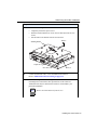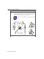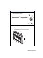
1
™
ENJOY THE FREEDOM OF WIRELESS NETWORKING
Access Point 2000 Installation Guide
ENTERASYS.COM
P/N 9034063-04
ELECTRICAL HAZARD: Only qualified personnel should perform installation
procedures.
NOTICE
Enterasys Networks and its licensors reserve the right to make changes in specifications and other information contained
in this document without prior notice. The reader should in all cases consult Enterasys Networks to determine whether
any such changes have been made.
The hardware, firmware, or software described in this manual is subject to change without notice.
IN NO EVENT SHALL ENTERASYS NETWORKS AND ITS LICENSORS BE LIABLE FOR ANY INCIDENTAL, INDIRECT,
SPECIAL, OR CONSEQUENTIAL DAMAGES WHATSOEVER (INCLUDING BUT NOT LIMITED TO LOST PROFITS)
ARISING OUT OF OR RELATED TO THIS MANUAL OR THE INFORMATION CONTAINED IN IT, EVEN IF ENTERASYS
NETWORKS AND ITS LICENSORS HAVE BEEN ADVISED OF, KNOWN, OR SHOULD HAVE KNOWN, THE POSSIBILITY
OF SUCH DAMAGES.
© February 2001 by Enterasys NetworksTM, Inc.
All Rights Reserved. Printed in the United States of America.
Enterasys Networks
35 Industrial Way
Rochester, NH 03867
Enterasys Networks, Inc. is a subsidiary of Cabletron Systems, Inc.
Order Number: 9034063-04
Enterasys, Enterasys Networks, NetRider, RoamAbout and the RoamAbout logo are trademarks or registered
trademarks of Cabletron Systems, Inc.
Apple, the Apple logo, Macintosh, and PowerBook are trademarks or registered trademarks of Apple Computer, Inc.
Microsoft, Windows, Windows 95, Windows 98, Windows NT, and Windows 2000 are either trademarks or registered
trademarks of Microsoft Corporation.
PC Card is a trademark of PCMCIA.
All other trademarks and registered trademarks are the property of their respective holders.
Web Site: http://www.enterasys.com/wireless
FCC Notice
Note: This equipment has been tested and found to comply with the limits for a Class B digital device,
pursuant to part 15 of the FCC Rules. These limits are designed to provide reasonable protection against
harmful interference in a residential installation. This equipment generates, uses and can radiate radio
frequency energy and, if not installed and used in accordance with the instructions, may cause harmful
interference to radio communications. However, there is no guarantee that interference will not occur in a
particular installation. If this equipment does cause harmful interference to radio or television reception,
which can be determined by turning the equipment off and on, the user is encouraged to try to correct the
interference by one or more of the following measures:
•
•
•
•
Reorient or relocate the receiving antenna.
Increase the separation between the equipment and receiver.
Connect the equipment into an outlet on a circuit different from that to which the receiver is connected.
Consult the dealer or an experienced radio/TV technician for help.
CAUTION: Changes or modifications made to this device which are not expressly
approved by the party responsible for compliance could void the user’s authority to
operate the equipment.
Industry Canada (Canada) - Class B Computing Device:
This Class B digital apparatus complies with Canadian ICES-003.
Cet appareil numérique de la classe B est conforme à la norme NMB-003 du Canada.
Europe - EC Declaration of Conformity
This device complies with Low Voltage Directive 73/23/EEC and EMC Directive 89/336/EEC.
VCCI Notice
This is a Class B product based on the standard of the Voluntary Control Council for Interference from
Information Technology Equipment (VCCI). If this is used near a radio or television receiver in a domestic
environment, it may cause radio interference. Install and use the equipment according to the instruction
manual.
Contents
Preface
Purpose of the Manual . . . . . . . . . . . . . . . . . . . . . . . . . . . . . . . . . . . . . . . . . . . . . . . . . . . . . . . . v
Intended Audience . . . . . . . . . . . . . . . . . . . . . . . . . . . . . . . . . . . . . . . . . . . . . . . . . . . . . . . . . . . v
Organization of this Document . . . . . . . . . . . . . . . . . . . . . . . . . . . . . . . . . . . . . . . . . . . . . . . . . v
Document Conventions . . . . . . . . . . . . . . . . . . . . . . . . . . . . . . . . . . . . . . . . . . . . . . . . . . . . . . vi
Associated Documents . . . . . . . . . . . . . . . . . . . . . . . . . . . . . . . . . . . . . . . . . . . . . . . . . . . . . . . vii
Getting Help . . . . . . . . . . . . . . . . . . . . . . . . . . . . . . . . . . . . . . . . . . . . . . . . . . . . . . . . . . . . . . viii
1 Preparing for Installation
In This Chapter. . . . . . . . . . . . . . . . . . . . . . . . . . . . . . . . . . . . . . . . . . . . . . . . . . . . . . . . . . . .
Reviewing the Site Requirements . . . . . . . . . . . . . . . . . . . . . . . . . . . . . . . . . . . . . . . . . . . . .
Hardware Requirements . . . . . . . . . . . . . . . . . . . . . . . . . . . . . . . . . . . . . . . . . . . . . . . . .
Electrical and Environmental Requirements . . . . . . . . . . . . . . . . . . . . . . . . . . . . . . . . .
Unpacking and Inspecting . . . . . . . . . . . . . . . . . . . . . . . . . . . . . . . . . . . . . . . . . . . . . . . . . . .
Basic Components . . . . . . . . . . . . . . . . . . . . . . . . . . . . . . . . . . . . . . . . . . . . . . . . . . . . .
Options . . . . . . . . . . . . . . . . . . . . . . . . . . . . . . . . . . . . . . . . . . . . . . . . . . . . . . . . . . . . . . . . . .
Other Considerations . . . . . . . . . . . . . . . . . . . . . . . . . . . . . . . . . . . . . . . . . . . . . . . . . . . . . . .
1-1
1-2
1-2
1-2
1-4
1-4
1-6
1-7
2 Cabling and Wiring
In This Chapter. . . . . . . . . . . . . . . . . . . . . . . . . . . . . . . . . . . . . . . . . . . . . . . . . . . . . . . . . . . .
Selecting a Power Configuration . . . . . . . . . . . . . . . . . . . . . . . . . . . . . . . . . . . . . . . . . . . . . .
Local Power Configuration. . . . . . . . . . . . . . . . . . . . . . . . . . . . . . . . . . . . . . . . . . . . . . .
Remote Power Configuration . . . . . . . . . . . . . . . . . . . . . . . . . . . . . . . . . . . . . . . . . . . . .
Redundant Power Configuration . . . . . . . . . . . . . . . . . . . . . . . . . . . . . . . . . . . . . . . . . .
Remote Power Adapter Installation . . . . . . . . . . . . . . . . . . . . . . . . . . . . . . . . . . . . . . . . . . . .
Remote Power Adapter Installation Procedure. . . . . . . . . . . . . . . . . . . . . . . . . . . . . . . .
2-1
2-2
2-2
2-2
2-2
2-3
2-4
iii
Table of Contents
Rack Mount Kit Installation. . . . . . . . . . . . . . . . . . . . . . . . . . . . . . . . . . . . . . . . . . . . . . . . . . 2-5
Overview. . . . . . . . . . . . . . . . . . . . . . . . . . . . . . . . . . . . . . . . . . . . . . . . . . . . . . . . . . . . . 2-5
Rack Mount Kit Installation Procedure . . . . . . . . . . . . . . . . . . . . . . . . . . . . . . . . . . . . . 2-6
Power Module Installation . . . . . . . . . . . . . . . . . . . . . . . . . . . . . . . . . . . . . . . . . . . . . . . . . . . 2-7
Installing the 120/240 Power Module. . . . . . . . . . . . . . . . . . . . . . . . . . . . . . . . . . . . . . . 2-7
Installing the 120 VAC Power Module . . . . . . . . . . . . . . . . . . . . . . . . . . . . . . . . . . . . . 2-8
Selecting the Correct Ethernet Wiring Configuration . . . . . . . . . . . . . . . . . . . . . . . . . . . . . . 2-8
Straight-Through Configuration . . . . . . . . . . . . . . . . . . . . . . . . . . . . . . . . . . . . . . . . . . . 2-9
Crossover Configuration. . . . . . . . . . . . . . . . . . . . . . . . . . . . . . . . . . . . . . . . . . . . . . . . . 2-9
CAT 5 Cabling Standards . . . . . . . . . . . . . . . . . . . . . . . . . . . . . . . . . . . . . . . . . . . . . . . . . . . 2 -9
MOD-TAP Connector. . . . . . . . . . . . . . . . . . . . . . . . . . . . . . . . . . . . . . . . . . . . . . . . . . 2-10
Cabling Standard EIA 568A . . . . . . . . . . . . . . . . . . . . . . . . . . . . . . . . . . . . . . . . . . . . . 2-11
Cabling Standard EIA 568B . . . . . . . . . . . . . . . . . . . . . . . . . . . . . . . . . . . . . . . . . . . . . 2-12
Cabling Standard EIA 356A . . . . . . . . . . . . . . . . . . . . . . . . . . . . . . . . . . . . . . . . . . . . . 2-13
Cabling Standard USOC . . . . . . . . . . . . . . . . . . . . . . . . . . . . . . . . . . . . . . . . . . . . . . . . 2-14
MOD-TAP Connector Wiring . . . . . . . . . . . . . . . . . . . . . . . . . . . . . . . . . . . . . . . . . . . . . . . 2-15
Power and Connector Specifications . . . . . . . . . . . . . . . . . . . . . . . . . . . . . . . . . . . . . . . . . . 2-17
3 Installing the Access Point
In This Chapter. . . . . . . . . . . . . . . . . . . . . . . . . . . . . . . . . . . . . . . . . . . . . . . . . . . . . . . . . . . . 3-1
Wall/Ceiling Outlet Box Installation . . . . . . . . . . . . . . . . . . . . . . . . . . . . . . . . . . . . . . . . . . . 3-2
Surface Wallmount Installation . . . . . . . . . . . . . . . . . . . . . . . . . . . . . . . . . . . . . . . . . . . . . . 3-10
Desktop Installation . . . . . . . . . . . . . . . . . . . . . . . . . . . . . . . . . . . . . . . . . . . . . . . . . . . . . . . 3-18
Connecting a Device to the Console Port . . . . . . . . . . . . . . . . . . . . . . . . . . . . . . . . . . . . . . 3-25
Verifying the Operation of the Access Point . . . . . . . . . . . . . . . . . . . . . . . . . . . . . . . . . . . . 3-27
Configuring the Access Point . . . . . . . . . . . . . . . . . . . . . . . . . . . . . . . . . . . . . . . . . . . . . . . 3-30
Using the RoamAbout Access Point Manager . . . . . . . . . . . . . . . . . . . . . . . . . . . . . . . 3-30
Using the RoamAbout Access Console Port . . . . . . . . . . . . . . . . . . . . . . . . . . . . . . . . 3-31
iv
Preface
Purpose of the Manual
This manual describes how to install and set up the RoamAbout Access Point 2000. It also
includes problem solving, and connector pin assignment information.
Intended Audience
This manual is intended for use by personnel who will install and set up the RoamAbout
Access Point 2000.
ELECTRICAL HAZARD: Only qualified personnel should perform
installation procedures.
Organization of this Document
This document is organized as follows:
Section
Description
Chapter 1
Contains pre-installation information you should know
before you install the RoamAbout Access Point 2000. This
includes the site requirements and specifications.
Chapter 2
Presents detailed step-by-step procedures to select,
configure, and install the correct power, cabling, and wiring
for your RoamAbout Access Point 2000.
Chapter 3
Contains detailed step-by-step procedures to install the
RoamAbout Access Point 2000.
v
Preface
Document Conventions
The following icons are used in this document:
Icon
Meaning
ELECTRICAL HAZARD: Warns against an action that could result
in personal injury or death.
WARNING
WARNING: Warns against an action that could result in personal
injury or death.
CAUTION: Contains information essential to avoid damage to the
equipment.
NOTE
vi
NOTE: Calls the reader’s attention to any item of information that
may be of special importance.
Preface
Associated Documents
The following table lists the RoamAbout products and information location. The
documentation, drivers, and utilities can also be downloaded from the RoamAbout
Wireless web site.
Check the RoamAbout Wireless web site regularly for product upgrades.
http://www.enterasys.com/wireless
Component
Information Location
RoamAbout Access Point
RoamAbout Access Point 2000 Hardware
Installation Quick Start
RoamAbout Access Point Manager
RoamAbout 802.11 Wireless Networking Guide
RoamAbout 802.11 PC Card Drivers
RoamAbout PC Card Drivers and Utilities
Client CD-ROM Kit
RoamAbout 802.11 PC Card Drivers and
Utilities Setup and Installation Guide
RoamAbout Client Utility
RoamAbout PC Card Drivers and Utilities
Client CD-ROM Kit
RoamAbout Work Station Update
RoamAbout PC Card Drivers and Utilities
Client CD-ROM Kit
RoamAbout ISA Adapter Card
RoamAbout ISA Adapter Installation
RoamAbout PCI Adapter Card
RoamAbout PCI Adapter Installation
RoamAbout Outdoor Solution
RoamAbout Outdoor Antenna Site Preparation
and Installation Guide
vii
Preface
Getting Help
For additional support related to this device or document, contact Enterasys Networks using one of
the following methods:
World Wide Web: http://www.enterasys.com/wireless
Phone:
North America: (603) 332-9400
Europe: 353 61 701 910
Asia: +800 8827-2878
Internet mail:
[email protected]
To send comments or suggestions concerning this document, contact the Enterasys
Networks Technical Writing Department via the following e-mail
address: [email protected]
Make sure you include the document Part Number in the e-mail message.
Before calling Enterasys Networks, please have the following information ready:
•
Your Enterasys Networks service contract number
•
A description of the problem
•
A description of any action(s) already taken to resolve the problem
•
The serial and revision numbers of all involved Enterasys Networks products in the network
•
A description of your network environment (for example, layout and cable type)
•
Network load and frame size at the time of trouble (if known)
•
The device history (for example, have you returned the device before, is this a recurring
problem)
•
Any previous Return Material Authorization (RMA) numbers
viii
Chapter 1
Preparing for Installation
This chapter describes basic considerations for successfully installing the RoamAbout
Access Point 2000 hardware. Before installing the Access Point (AP), you must complete
the following tasks:
•
Review the site requirements.
•
Select the location to install the AP.
•
Unpack the AP and check the contents of the shipment.
In This Chapter
Information in this chapter is presented as follows:
Topic
Page
Reviewing the Site Requirements
1-2
Unpacking and Inspecting
1-4
Basic Components
1-4
Options
1-6
Other Considerations
1-7
If installing the Access Point in a building-to-building configuration, refer to the
RoamAbout Outdoor Antenna Site Preparation and Installation Guide for the proper
antenna cabling and grounding procedures.
After you install the Access Point, refer to the RoamAbout 802.11 Wireless Networking
Guide to configure the Access Point parameters.
Preparing for Installation 1-1
Reviewing the Site Requirements
Reviewing the Site Requirements
Please review the site requirements before you install the Access Point.
Hardware Requirements
Table 1-1: AP Physical Specifications (with plastic cover)
Parameter
Access Point
Width
17.9 cm (7.06 in)
Height
16.8 cm (6.64 in)
Depth
4.1 cm (1.63 in)
Weight
.86 kg (1.9 lb)
Electrical and Environmental Requirements
Ensure that the environmental and electrical requirements are within the ranges described
in Table 1-2 through Table 1-4.
Table 1-2: Environmental Specifications
Parameter
Description
Operating Environment
Temperature1
5°C to 50°C (41°F to 122°F)
Relative humidity
15% to 90% (non-condensing)
Altitude above sea level
2.4 km (8000 ft.)
Air flow
Convection cooled
Nonoperating Environment
Temperature
-40°C to 66°C (-40°F to 151°F)
Relative humidity
15 to 90% (non-condensing)
Altitude
Up to 4.9 km (16,000 ft)
1For
sites above 4900 m (16,000 ft.), decrease the operating temperature specification by 1.8°C for
each 1000 m or 3.2°F for each 3200 ft.
1-2 Preparing for Installation
Reviewing the Site Requirements
Table 1-3: AP Power Supply Specifications (US)
Parameter
Value
Input voltage
120 VAC
Input Current at 120 V
220 mA
Frequency
60 Hz
Output voltage
24 VAC
Output current (maximum)
500 mA
Table 1-4: AP Power Supply Specifications (World)
Parameter
Value
Input voltage
100 VAC to 240 VAC
Input Current at 120 V
400 mA
Frequency
47 Hz to 63 Hz
Output voltage
24 VDC
Output current (maximum)
625 mA
Preparing for Installation 1-3
Unpacking and Inspecting
Unpacking and Inspecting
Physically inspect all cartons for shipping damage. Report any damage to your shipping
carrier. Also verify that you have received the correct basic components and options as
listed on the following pages. Report any discrepancies to your Enterasys Sales
Representative.
Basic Components
The basic components required for installation include an Access Point and a PC Card.
4A
2
3
1
4B
5
7
6
8
Access Point
Verify that the following components shipped with your Access Point:
#
Description
Part Number
1
Access Point
CSIWS-A
2
Wall/Ceiling Mounting Bracket
9901132
3
Plastic Cover
8020216
NOTE
1-4 Preparing for Installation
A security box, sold
separately, is available.
Contact your Enterasys
Representative for more
information.
Unpacking and Inspecting
#
Description
Part Number
4A
Power Module (120/240 VAC)*
CSIWS-PS1
4B
Power Module (120 VAC)*
5652041
(Model No. : FE4830 240A050)
5
Cable, RJ45 Male to RJ45 Male, 7 inch
9360119-7"
6
RJ45 to Punch-Down Conn. (Mod
Tap)
6370006
7
Remote Power Adapter
8917544
8
Four Rubber Feet
5020005
* Only use UL Listed Class 2 power supplies with this product.
PC Card
Verify that you have received the correct PC Card for your particular system configuration:
Part Number
Description
FCC
ETSI
France
Japan
11 Mbit/s PC Card
(40-Bit encryption)
CSIBD-AA
CSIBD-AB
CSILD-AB*
CSIBD-AF
CSILD-AF*
CSIBD-AJ
CSILD-AJ*
11 Mbit/s PC Card
(128-Bit encryption)
CSIBD-AA-128
CSIBD-AB-128
CSILD-AB-128*
CSIBD-AF-128
CSILD-AF-128*
CSIBD-AJ-128
CSILD-AJ-128*
* This part number is for the Hi-Gain matched RoamAbout PC Card, which is required in the specified countries when
connecting the PC Card to the RoamAbout 14 dBi directional antenna.
Preparing for Installation 1-5
Options
Options
The following options are available for the Access Point:
1
.
3
2
4
#
Description
Part Number
1
Redundant Power Supply
(with four International Power Adapters)
CSIWS-PS1
2
Rack Mount Kit
CSIWS-RM
3
Range Extender Antenna
CSIBB-IA
4
Security Box
CSIWS-WM
1-6 Preparing for Installation
Other Considerations
Other Considerations
Enterasys Networks recommends that you test the coverage area before you permanently
install the Access Point. The coverage area is where wireless clients can be physically
located and still connect to the Access Point. Coverage area is determined by a number of
factors, including the speed of the RoamAbout PC Card, physical obstructions, and noise
levels.
If possible, temporarily connect the Access Point and use the RoamAbout utilities
described in the RoamAbout 802.11 Wireless Networking Guide to determine the actual
coverage area. Using these tools can help you determine the best place to mount the Access
Point.
If you are using an outdoor antenna with the Access Point, consider the following factors:
•
Type of antenna.
•
Outdoor antenna installation.
•
Grounding system. The Access Point and the outdoor antenna must use the same
grounding system. Refer to the RoamAbout Outdoor Antenna Site Preparation and
Installation Guide for the detailed procedures to install outdoor antennas.
Preparing for Installation 1-7
Chapter 2
Cabling and Wiring
This chapter presents detailed step-by-step procedures to select, configure, and install the
correct power, cabling, and wiring for your RoamAbout Access Point 2000.
In This Chapter
Information in this chapter is presented as follows:
Topic
Page
Selecting a Power Configuration
2-2
Remote Power Adapter Installation
2-3
Rack Mount Kit Installation
2-5
Power Module Installation
2-7
Selecting the Correct Ethernet Wiring Configuration
2-8
CAT 5 Cabling Standards
2-9
MOD-TAP Connector Wiring
2-15
Power and Connector Specifications
2-17
CAUTION: The Enterasys 5652041 North American AC Power
Supply (for the CSIWS-AA Access Point) has an internal 1-ampere
non-replaceable fuse. If the fuse blows due to remote power cable
miswiring, the power supply must be replaced.
The Enterasys 5652042 International DC Power Supply (ships with
the CSIWS-AB Access Point) and the CSIWS-PS1 Redundant DC
Power Supply (for either the CSIWS-AA or CSIWS-AB) have overload
protection. If an overload occurs because of miswiring or some other
fault, the power supply voltage folds back to protect the power supply,
the site wiring, and the Access Point from damage.
Cabling and Wiring 2-1
Selecting a Power Configuration
Selecting a Power Configuration
The power configurations available for the Access Point include local power, remote
power, and redundant power.
Local Power Configuration
In the local power configuration, the Access Point receives operating power directly from
one local source (such as a power module connected to a nearby wall outlet). The output
plug of the power module is connected directly into the Access Point chassis-mounted
power connector.
Remote Power Configuration
In the remote power configuration, the Access Point receives operating power over the
Ethernet cable from one remote source (such as a power module installed in the wiring
closet or other remote location). This option requires installing the remote power adapter
in the same location as the power module. The output of the power module is connected to
the remote power adapter. The Ethernet interface cable also plugs into the remote power
adapter. Another Ethernet cable is connected between the adapter and the Access Point to
provide input/output signals and power.
The Enterasys 5652041 North American AC Power Supply (for the
CSIWS-AA Access Point) has an internal 1-ampere non-replaceable
fuse. If the fuse blows due to remote power cable miswiring, the power
supply must be replaced.
If you are using the remote power adapter with the Enterasys North
American AC Power Supply, label the cable at the opposite end from
the power adapter (Access Point, MOD-TAP connector, or wall jack)
to ensure that this cable is not connected to another device. The
procedures in Chapter 3 offer sample text.
Enterasys offers an optional rack mount kit that allows installation of up to three remote
power adapters into one standard rack-mount panel.
Redundant Power Configuration
The Access Point can be connected to an independent source of local power and to an
independent source of remote power. If one of these power sources goes down, the Access
Point continues uninterrupted operation with power received from the other (redundant)
power source.
2-2 Cabling and Wiring
Remote Power Adapter Installation
Remote Power Adapter Installation
The remote power adapter provides operating power to the Access Point using the Ethernet
cable. The adapter receives input power (via the PWR jack) from either the power module
supplied with the Access Point or directly from the site facility. If using the power module,
install the adapter within six feet of an AC power outlet. The network interface cable plugs
into the NETWORK jack, and the Access Point cable plugs into the ACCESS POINT jack.
ACCESS
J2
POINT
NETWORK
J1
1
2
3
4
5
6
7
8
To Customer
Network
1
2
3
4
5
6
7
8
2
Remote
Power
Adapter
Network
PWR
J3
Pin
1
PWR
Access
Point
8
1
8-pin MJ connector
Pin
Network Connector
Access Point
Connector
1
XMIT Data Positive
XMIT Data Positive
2
XMIT Data Negative
XMIT Data Negative
3
RCV Data Positive
RCV Data Positive
4
No Connection
Remote Power 1
5
No Connection
Remote Power 2
6
RCV Data Negative
RCV Data Negative
7
No Connection
Remote Power 1
8
No Connection
Remote Power 2
Power
Connector
1
Remote Power 1
2
Remote Power 2
Cabling and Wiring 2-3
Remote Power Adapter Installation
Remote Power Adapter Installation Procedure
Use the following procedure to install the remote power adapter.
Step
Action
1
If available, use a cable tester to check the cable wiring to the Access Point.
Check continuity and pairing.
2
3
Select a mounting location:
•
Close to the Ethernet wiring panel or Ethernet port.
•
Within six feet of an AC power outlet (if remote power is used).
Secure the remote power
adapter.
Mounting
Hole (2)
If necessary, use the two wall
anchors provided in your
installation kit.
4
5
Insert the Ethernet cable
connector into the NETWORK
jack.
Network
PWR
Access
Point
Insert the Access Point cable
connector into the ACCESS
POINT jack.
Before you connect to the remote power adapter, verify that the wired
network connector is inserted into the NETWORK jack, and the
Access Point is connector is inserted into the ACCESS POINT jack.
6
Proceed to Chapter 3, Installing the Access Point.
2-4 Cabling and Wiring
Rack Mount Kit Installation
Rack Mount Kit Installation
Overview
The rack mount kit allows you to install up to three remote power adapters into one standard
rack-mount panel to provide for the operation of up to three Access Points.
The information presented in the Remote Power Adapter Installation on page 2-3
applies to each of the three remote power adapters in the rack mount kit.
The rack mount panel installation procedure is on the next page.
Cabling and Wiring 2-5
Rack Mount Kit Installation
Rack Mount Kit Installation Procedure
Use the following procedure to install the rack mount kit.
Step
Action
1
If available, use a cable tester to check the cable wiring to each Access
Point.
Check continuity and pairing.
2
3
Select a mounting location:
•
Close to the Ethernet wiring panel.
•
Within six feet of an AC power outlet (if remote power is used).
Install up to three remote power adapters within the rack mount panel.
Use the screws provided in the rack mount kit to secure each remote power
adapter to the rack mount panel.
4
Secure the rack mount panel to the rack using the screws provided in the kit.
5
Insert an Ethernet cable connector into the NETWORK jack of one of the
remote power adapters.
6
Insert an Access Point cable connector into the ACCESS POINT jack of the
same remote power adapter.
Before you connect to the remote power adapter, verify that the wired
network connector is inserted into the NETWORK jack, and the
Access Point is connector is inserted into the ACCESS POINT jack.
7
Repeat Steps 5 and 6 for each Access Point.
8
Proceed to Chapter 3, Installing the Access Point.
2-6 Cabling and Wiring
Power Module Installation
Power Module Installation
Installing the 120/240 Power Module
Perform the following steps to install the 120/240 Power Module:
Step
Action
1
Verify that you have the correct power module and adapters.
2
Insert the appropriate adapter into the power module.
Do not connect the power
module to the primary source
until instructed to do so.
.
Cabling and Wiring 2-7
Selecting the Correct Ethernet Wiring Configuration
Installing the 120 VAC Power Module
Do not connect the power module to the primary power source until
instructed to do so.
The only installation required for the 120 VAC Power Module is to plug it into an
appropriate wall outlet or extension cord.
Selecting the Correct Ethernet Wiring Configuration
If you have an existing 10BaseT Ethernet cable in place, you can connect the cable directly
to the Access Point. You can also connect the Ethernet cable to the remote power adapter,
then connect the remote power adapter to the Access Point.
If you plan to connect the Ethernet cable to the Access Point using a MOD-TAP connector,
refer to the following sections for information on the CAT 5 cabling standards and wiring
the MOD-TAP connector.
To ensure correct system operation, make sure you select the appropriate straight-through
or crossover Ethernet wiring configuration for your installation.
2-8 Cabling and Wiring
CAT 5 Cabling Standards
Straight-Through Configuration
Use a straight-through wiring configuration if connecting:
•
An Ethernet switching device to an Access Point.
•
An Access Point to a remote power adapter.
Crossover Configuration
Use a crossover wiring configuration if connecting:
•
An Access Point to an Access Point.
•
An Access Point to an Ethernet card in a PC.
CAT 5 Cabling Standards
There are four common CAT 5 Cabling Standards. Three of these, EIA 568A, EIA 568B,
and EIA 356A are recommended for RoamAbout Access Point 2000 installations. The
fourth standard, USOC, has advantages when dealing with telephone wiring but is strongly
not recommended for use in data applications.
•
If new wiring is installed for the Access Point, it is extremely important to know which
standard was used to install the existing wiring.
•
It is also important that new wiring complies with and is tested to CAT 5 Cabling
Standards. Miswiring of data pairs can result in a faulty Ethernet connection.
Miswiring of power pairs could blow a fuse in the North American power supply.
Crossing data and power wiring pairs could also result in a blown fuse.
•
In the event of data or power miswiring when using RoamAbout power supplies, the
North American power supply can blow a fuse and the International Power supply
folds back. In either case, the Access Point is not damaged but the North American
Power Supply may have to be replaced.
•
If you are not using a RoamAbout power supply, miswiring of data or power may
damage the Access Point. Again, use care when installing the wiring for the Remote
Power feature.
NOTE
All CAT 5 information presented here also applies to CAT 3.
Cabling and Wiring 2-9
CAT 5 Cabling Standards
MOD-TAP Connector
Enterasys provides a MOD-TAP connector for terminating building wiring at the Access
Point.
Before installing each individual color-coded wire into the MOD-TAP connector,
determine the cable standard to be used (see pages 2-11, 2-12, and 2-13). Based on the
standard chosen, orient the connector in the "A" configuration or the "B" configuration
position as shown below:
"A" Configuration
2-10 Cabling and Wiring
"B" Configuration
CAT 5 Cabling Standards
Cabling Standard EIA 568A
2
1
3
Gr
W
hit
e/
Gr
ee een
n
W /Wh
hit
ite
e
Bl / O r a ( G r
ue
e
/W nge en)
hit
W
e
hi t
e/ B ( B l u
e)
Or
l
an ue
ge
W
hit /Wh
ite
e/
B r B r ow ( O r
ow
an
ge
n/ W n
)
hi t
e(
Br
ow
n)
This is the latest sequence option as published in TIA Commercial Building Cabling
Specification 568A. If using the Enterasys supplied MOD-TAP connector, use the "A"
wiring configuration for the EIA 568A wiring scheme.
4
5
6
7
8
EIA 568A
Cable Pairings/Pin Assignments
Brown/White (Brown*)
White/Brown
Orange/White (Orange*)
Blue/White (Blue*)
MOD-TAP Connector
"A" Wiring Configuration
White/Green
Green/White (Green*)
White/Orange
White/Blue
* (color) = Solid Color
Cabling and Wiring 2-11
CAT 5 Cabling Standards
Cabling Standard EIA 568B
W
hit
e
/
Or Ora
ng
an
e
g
W e/W
hit
hit
e
Bl /Gre e (O
ue
ra
/W en
ng
e)
hit
W
e(
hit
B
e
lue
Gr /Blu
)
e
ee
n/W
W
h
hit
e/B ite (
G
r
Br
ow own reen
)
n/W
hit
e(
Br
ow
n)
This standard is the most widely specified sequence worldwide for new data installations.
It is also a subset specified by the IEEE 802.3 10BASE-T Ethernet over twisted pair
standard. If using the Enterasys supplied MOD-TAP connector, use the "B" wiring
configuration for the EIA 568B wiring scheme.
1
2
3
4
5
6
7
8
EIA 568B
Cable Pairings/Pin Assignments
White/Orange
Orange/White (Orange*)
White/Green
White/Blue
MOD-TAP Connector
"B" Wiring Configuration
Brown/White (Brown*)
White/Brown
Green/White (Green*)
Blue/White (Blue*)
* (color) = Solid Color
2-12 Cabling and Wiring
CAT 5 Cabling Standards
Cabling Standard EIA 356A
W
hit
e
/
Or Ora
ng
an
e
g
W e/W
hit
hit
e
Bl /Gre e (O
ue
ra
/W en
ng
e)
hit
W
e
hit
e/B (Blu
e)
Gr
l
ee ue
n/W
W
h
hit
e/B ite (
G
r
Br
ow own reen
)
n/W
hit
e(
Br
ow
This standard is a 3-pair subset of EIA 568B, leaving out the Brown/White - White/Brown
pair. If using the Enterasys supplied MOD-TAP connector, use the "B" wiring diagram for
the EIA 356A wiring scheme.
Cable Pairings
1
2
3
4
5
6
7
8
EIA 356A
Cable Pairings/Pin Assignments
White/Orange
Orange/White (Orange*)
White/Green
White/Blue
MOD-TAP Connector
"B" Wiring Configuration
Green/White (Green*)
Blue/White (Blue*)
* (color) = Solid Color
Cabling and Wiring 2-13
CAT 5 Cabling Standards
Cabling Standard USOC
Br
ow
n/
W
hit
W
e(
hit
Br
e/G
ow
re
n)
W
e
n
hit
e/O
ra
Bl
ng
ue
e
/W
hit
W
e
hi
(B
lue
Or te/B
an lue
)
Gr ge
ee /W
W n/W hite
hit
h (
e/B ite Ora
ro (Gr nge
wn ee )
n)
This standard is shown for reference only and is strongly not recommended for use in data
applications.
1
2-14 Cabling and Wiring
2
3
4
5
6
7
8
MOD-TAP Connector Wiring
MOD-TAP Connector Wiring
1
2
Determine the appropriate CAT 5 Cabling standard for your installation:
•
Refer to “CAT 5 Cabling Standards” on page 2-9.
•
Select the cabling standard appropriate for your site.
Remove the rubber protector
from the MOD-TAP
connector.
Rubber Protector
3
Remove the plastic cover from the MOD-TAP connector. The plastic cover
is also used as a MOD-TAP wire insertion tool.
4
Locate the 10BaseT Ethernet network cable in the wall box.
5
Insert each Ethernet cable wire into the correct MOD-TAP connector slot
according to the appropriate CAT 5 Cabling Standard for your site.
Cabling and Wiring 2-15
MOD-TAP Connector Wiring
6
7
Secure each Ethernet cable wire in its correct MOD-TAP connector slot:
•
Do not remove insulation from any wire.
•
With each wire firmly in place in its correct slot, reinstall the
MOD-TAP wire insertion tool/cover.
•
Secure all wires by pushing down firmly on the MOD-TAP wire
insertion tool/cover.
Install the remote power feature or the rack mount kit, if used.
Refer to Remote Power Adapter Installation on page 2-3 or the Rack
Mount Kit Installation on page 2-5.
8
Use a CAT 5-compatible cable tester to verify continuity, correct pinouts,
and correct pairings.
9
Proceed to Chapter 3, Installing the Access Point.
2-16 Cabling and Wiring
Power and Connector Specifications
Power and Connector Specifications
Access Point power and connector specifications are listed in the table below. These
specifications are provided for customers who want to provide their own site operating
power for the Access Point.
If the remote power feature is used, Enterasys strongly recommends that you test the cable
from the remote power adapter to the Access Point for continuity and correct pinout
(straight-through cable) before power is applied. Enterasys assumes no responsibility if the
specifications set forth below are not followed.
Specification
Rating
Power
Consumption
5 Watts with 9 to 60 Volts DC
7 Watts with 10 Volts AC to 30 Volts AC
Voltage Input
9 to 60 Volts DC
555 mA @ 9 Volts DC to 83 mA @ 60 Volts DC
Polarity Independent
or
10 Volts AC to 30 Volts AC
500 mA @ 10 Volts AC to 167 mA @ 30 Volts AC
Regulation
Regulated or non-regulated UL Listed Class 2 power supplies may be
used.
Non-regulated power supply outputs should not exceed the stated
maximum voltages and should not fall below the stated minimum
voltages.
Redundant Power
Application
Redundant power may be applied to the Access Point.
Both power connections (front panel and Ethernet) are electrically
isolated.
Redundant power sources do not need to be matched for voltage or
polarity.
AC and DC sources may be used at the same time.
Power Connector
Coaxial Type Power Plug that mates with Switchcraft RAPC712 Jack
(Switchcraft 760 or equivalent).
Dimensions:
Inside Diameter: 2.5 mm (0.100 inches)
Outside Diameter: 5.5 mm (0.218 inches)
Barrel Length: 9.5 mm (0.375 inches)
Cabling and Wiring 2-17
Chapter 3
Installing the Access Point
This chapter provides the procedures to install the Access Point 2000 and its options.
Make sure the site primary power for the Access Point conforms to the specifications
detailed in Chapter 2 - Cabling and Wiring.
If using a BootP/TFTP server and the Access Point Manager to configure the Access Points
with IP addresses, you should configure the server BEFORE applying power to each
Access Point. Upon power-up, each Access Point automatically sends a BootP request.
If you plan to use the Access Point Manager program, write down the MAC address listed
on the front of the Access Point. For a LAN-to-LAN configuration, also write down the
MAC address on the back of the PC Card, which is the wireless MAC address.
In This Chapter
Information in this chapter is presented as follows:
Topic
Page
Wall/Ceiling Outlet Box Installation
3-2
Surface Wallmount Installation
3-10
Desktop Installation
3-18
Connecting a Device to the Console Port
3-25
Verifying the Operation of the Access Point
3-27
Configuring the Access Point
3-30
Installing the Access Point 3-1
Wall/Ceiling Outlet Box Installation
Wall/Ceiling Outlet Box Installation
Follow the step-by-step procedure below to install the Access Point to an outlet box.
Step
Action
1
Make sure the site primary power for the Access Point conforms to the
specifications detailed in Chapter 2 - Cabling and Wiring.
2
Select a wall or ceiling outlet:
•
If using remote power, with internal 10BaseT Ethernet network cabling
installed.
•
If not using remote power, within five feet of an AC electrical outlet:
a) If using redundant power (connecting both local power and remote
power).
or
b) If using the local power option and not using the remote power
option.
3-2 Installing the Access Point
Wall/Ceiling Outlet Box Installation
Step
Action
3
Remove the mounting bracket from the Access Point:
•
Completely loosen the captive screw.
•
Slide the bracket until the two screw slots are directly below the two
screws.
•
Lift and remove the bracket from the Access Point.
Remove
Mounting Bracket
fig1
Captive Screw
Screw Slot (2)
4
Screw (2)
Connect the Ethernet cable, or wire the MOD-TAP connector:
Refer to MOD-TAP Connector Wiring on page 2-15.
5
Before installing the metal mounting bracket, make certain that the
mounting holes on the bracket line up with those on the outlet box.
Additional holes may be drilled in the bracket to accommodate your
particular installation.
NOTE
Remove all drilled material from the area.
Installing the Access Point 3-3
Wall/Ceiling Outlet Box Installation
Step
Action
6
If using a MOD-TAP connector, install the wired MOD-TAP connector:
•
Insert the connector through the rear of the metal mounting bracket tab.
•
Push the connector until it securely locks into the tab.
NOTE
Make sure the slot on the MOD-TAP connector is facing down.
Insert
Slot
Lock
7
Secure the mounting bracket to the wall outlet box.
3-4 Installing the Access Point
Wall/Ceiling Outlet Box Installation
Step
Action
8
If using a MOD-TAP connector, connect one end of the 7-inch RJ45 Male
cable to the MOD-TAP connector.
9
Secure the Access Point to the mounting bracket:
•
Insert the two Access Point shoulder screws into the two mounting
bracket screw slots.
•
Slide the Access Point down.
•
Tighten the captive screw to secure the Access Point.
Captive Screw
S1
S2
MA
AD C
D
SN
Install
ww
w.c
a
ble
tro
n.c
om
/w
TU
ire
V
les
s
2
1
fig6a
Installing the Access Point 3-5
Wall/Ceiling Outlet Box Installation
Step
Action
10
Install the PC Card:
•
Position the card as shown below.
•
Carefully insert the card.
•
Press down firmly to seat the card.
PC Card
SS11
SS22
MMAA
AADDCC
DD
SSNN
wwww
ww.c.c
aabble
letrtr
oonn.c
.coo
mm/w
/w
irireele
less
ss
TTUU
VV
22
3-6 Installing the Access Point
11
Wall/Ceiling Outlet Box Installation
Step
Action
11
If you install the optional range extender
antenna or outdoor antenna:
•
Remove the dust cover.
•
Insert the antenna plug into the PC Card
connector.
•
Gently press down on the plug to secure
the antenna connection.
Installing the Access Point 3-7
Wall/Ceiling Outlet Box Installation
Step
Action
12
Install the remote power adapter or the rack mount kit, if used.
Refer to Remote Power Adapter Installation on page 2-3 or Rack
Mount Kit Installation on page 2-5.
If you are using remote power, connect the output of the remote power
module to the PWR jack on the remote power adapter.
Remote
Power
Adapter
Network
13
PWR
Access
Point
Install the power module/redundant power module, if used.
Refer to Power Module Installation on page 2-7.
Connect the output of the power module/
redundant power module to the Access Point.
S1
S2
14
Connect the power module into an AC outlet.
15
Verify power on by observing that some of the Access Point LEDs are
flashing or lit.
3-8 Installing the Access Point
Wall/Ceiling Outlet Box Installation
Step
Action
16
Secure the cover:
•
Position the cover over the Access Point.
•
Make sure the cover clears the antenna plug.
•
Push the cover down until all four snaps are secured.
S1
S2
MAC
AD
D
SN
Snaps (4)
Wir
ele
ss
LA
Ns
ww
w.ca
blet
ron.
co
m/w
TU
V
ire
less
2
1
Installing the Access Point 3-9
Surface Wallmount Installation
Surface Wallmount Installation
Follow the step-by-step procedure below to install the Access Point on the surface of a wall,
cubical wall, vertical support structure, or ceiling.
Step
Action
1
Make sure the site primary power for the Access Point conforms to the
specifications detailed in Chapter 2 - Cabling and Wiring.
2
Select the optimum mounting location:
•
With easy access for inspection and service.
•
If using remote power, close to the 10BaseT Ethernet network cable
connector.
•
If not using remote power, within five feet of an AC electrical outlet:
a) If using redundant power (connecting both local power and remote
power).
or
b) If using the local power option and not using the remote power
option.
3-10 Installing the Access Point
Surface Wallmount Installation
Step
Action
3
Remove the mounting bracket from the Access Point:
•
Completely loosen the captive screw.
•
Slide the bracket until the two screw slots are directly below the two
mounting screws.
•
Lift and remove the bracket from the Access Point.
Remove
Mounting Bracket
fig1
Captive Screw
Screw (2)
Screw Slot (2)
4
Flatten the metal mounting bracket tab against the bracket, or remove the
tab by bending it back and forth.
Tab
fig1a
Installing the Access Point 3-11
Surface Wallmount Installation
Step
Action
5
Secure the mounting bracket to the wall:
•
Locate at least two mounting holes/slots on the mounting bracket that
line up with a wall stud.
•
Use two screws to secure the mounting bracket to the wall stud.
•
Use plastic anchors and screws, or self-anchoring screws to secure the
mounting bracket to the wallboard.
NOTE
Additional holes may be drilled in the bracket to accommodate
your particular installation. Remove all drilled material from
the area.
Mounting
Holes/Slots
3-12 Installing the Access Point
Surface Wallmount Installation
Step
Action
6
Secure the Access Point to the mounting bracket:
•
Insert the two Access Point shoulder screws into the two mounting
bracket screw slots.
•
Slide the Access Point down.
•
Tighten the captive screw to secure the Access Point.
Captive Screw
S1
S2
MA
AD C
D
SN
Install
ww
w.c
a
ble
tro
n.c
om
/w
TU
ire
V
les
s
2
1
fig6a
Installing the Access Point 3-13
Surface Wallmount Installation
Step
Action
7
Install the PC Card:
•
Position the card as shown below.
•
Carefully insert the card.
•
Press down firmly to seat the card.
PC Card
S1
S2
MA
AD C
D
SN
ww
w.c
a
ble
tro
n.c
om
/w
TU
ire
V
les
s
2
3-14 Installing the Access Point
1
Surface Wallmount Installation
Step
Action
8
If you install the optional range extender
antenna or outdoor antenna:
9
•
Remove the dust cover.
•
Insert the antenna plug into the PC Card
connector.
•
Gently press down on the plug to secure
the antenna connection.
Install the remote power adapter or the rack mount kit, if used.
Refer to Remote Power Adapter Installation on page 2-3 or the Rack
Mount Kit Installation on page 2-5.
Connect the output of the remote power module to the PWR jack on the
remote power adapter.
Remote
Power
Adapter
Network
PWR
Access
Point
Installing the Access Point 3-15
Surface Wallmount Installation
Step
Action
10
Connect the 10BaseT
Ethernet network cable.
If you are using the remote
power feature, label the end
of the cable to the Access
Point with: CAUTION:
Ethernet cable contains
power. Do not use for other
devices.
If you are not using remote
power, install the power
module/redundant power
module, if used; refer to
Power Module Installation
on page 2-7.
S1
Power
Connector
S2
Ethernet
Cable
Connector
11
Connect the power module into an AC outlet.
12
Verify power on by observing that some of the Access Point LEDs are
flashing or lit.
3-16 Installing the Access Point
Surface Wallmount Installation
Step
Action
13
Secure the cover:
•
Position the cover over the Access Point.
•
Make sure the cover clears the antenna plug.
•
Push the cover down until all four snaps are secured.
S1
S2
MAC
AD
D
SN
Snaps (4)
Wir
ele
ss
LA
Ns
ww
w.ca
blet
ron.
co
m/w
TU
V
ire
less
2
1
Installing the Access Point 3-17
Desktop Installation
Desktop Installation
To install the Access Point on a desktop, do the following:
Step
Action
1
Make sure the site primary power for the Access Point conforms to the
specifications detailed in Chapter 2 - Cabling and Wiring.
2
Select a desktop location:
•
If using remote power, close to the 10BaseT Ethernet network cable
connector.
•
If not using remote power, within five feet of an AC electrical outlet:
a) If using redundant power (connecting both local power and remote
power).
or
b) If using the local power option and not using the remote power
option.
3-18 Installing the Access Point
Desktop Installation
Step
Action
3
Remove the mounting bracket from the Access Point:
•
Completely loosen the captive screw.
•
Slide the bracket until the two screw slots are directly below the two
shoulder mounting screws.
•
Lift and remove the bracket from the Access Point.
Remove
Mounting Bracket
fig1
Captive Screw
Screw Slot (2)
4
Shoulder
Screw (2)
Remove the captive screw bracket by removing two screws.
Screw (2)
Bracket
fig2
5
Re-install the two screws.
Installing the Access Point 3-19
Desktop Installation
Step
Action
6
Install the four rubber feet on the bottom of the Access Point.
NOTE
Exact placement of each rubber foot is not crucial. For
maximum stability, install each rubber foot as close to a corner
of the Access Point as possible.
fig11
3-20 Installing the Access Point
Desktop Installation
Step
Action
7
Install the PC Card:
•
Position the card as shown below.
•
Carefully insert the card.
•
Press down firmly to seat the card.
PC Card
S1
S2
MA
AD C
D
SN
ww
w.c
a
ble
tro
n.c
om
/w
TU
ire
V
les
s
2
1
Installing the Access Point 3-21
Desktop Installation
Step
Action
8
If you install the optional range extender
antenna or outdoor antenna:
9
•
Remove the dust cover.
•
Insert the antenna plug into the PC Card
connector.
•
Gently press down on the plug to secure
the antenna connection.
Install the remote power adapter or the rack mount kit, if used.
Refer to Remote Power Adapter Installation on page 2-3 or the Rack
Mount Kit Installation on page 2-5.
Connect the output of the remote power module to the PWR jack on the
remote power adapter.
Remote
Power
Adapter
Network
3-22 Installing the Access Point
PWR
Access
Point
Desktop Installation
Step
Action
10
Connect the 10BaseT
Ethernet network cable.
If you are using the remote
power feature, label the end
of the cable to the Access
Point with: CAUTION:
Ethernet cable contains
power. Do not use for other
devices.
If you are not using remote
power, install the power
module/redundant power
module, if used; refer to
Power Module Installation
on page 2-7
S1
Power
Connector
S2
Ethernet
Cable
Connector
11
Connect the power module into an AC outlet.
12
Verify power on by observing that some of the Access Point LEDs are
flashing or lit.
Installing the Access Point 3-23
Desktop Installation
Step
Action
13
Secure the cover:
•
Position the cover over the Access Point.
•
Make sure the cover clears the antenna plug.
•
Push the cover down until all four snaps are secured.
S1
S2
MAC
AD
D
SN
Snaps (4)
Wir
ele
ss
LA
Ns
ww
w.ca
blet
ron.
co
m/w
TU
V
ire
less
2
3-24 Installing the Access Point
1
Connecting a Device to the Console Port
Connecting a Device to the Console Port
You can manage the Access Point using its console port or using the RoamAbout Access
Point Manager program. You do not need to use the console port if you use the Access Point
Manager. These management tools are described in the RoamAbout 802.11 Wireless
Networking Guide.
You can connect a terminal or personal computer running terminal emulation software to
the console port. Signals from the console port conform to the EIA-232D signaling standard
at 9600 baud only. The port appears as a data terminal equipment (DTE) device. To connect
a device to the Access Point console port, do the following:
1) Choose a device (terminal or personal computer) to connect to the Access
Point.
2) Connect a null modem cable or equivalent to the device and the Access Point:
Pin
1
2
3
4
5
6
7
8
9
Assignment
Data Carrier Detect (DCD)
Receive Data (RXD)
Transmit Data (TXD)
Data Terminal Ready (DTR)
Ground
Data Set Ready (DSR)
Request to Send (RTS)
Clear to Send (CTS)
No connect
1
6
5
9
LKG-8996-931-01
3) If using a terminal, configure the transmit and receive baud rates to 9600 baud
only.
4) If using a personal computer, configure a terminal emulation application to
use 9600 baud transmit and receive rates. The following is an example of
configuring the Microsoft Windows Hyperterminal application:
a) Open the Hyperterminal application, which is usually located in
Programs→Accessories→Hyperterminal.
b) Create a new connection. Depending on the system configuration,
Hyperterminal could automatically prompt you for a new connection
name. Choose a name that identifies the connection type, such as Access
Point Console Port.
c) Ignore or cancel any prompts for modem or phone information.
Installing the Access Point 3-25
Connecting a Device to the Console Port
d) In a Connect Using or similar field, select the port that is connected to
the Access Point, such as COM1.
e) In the Port Settings window, enter:
— Bits per second: 9600
— Data bits: 8
— Parity: None
— Stop Bits: 1
— Flow Control: Hardware
To connect to the console port at a later date, open Hyperterminal and
select File→Open to open the Access Point Console Port connection.
5) Press <Enter> a few times until the RoamAbout Access Point Installation
Menu is displayed. The installation menu allows you to display and modify
various Access Point and wireless networking parameters.
3-26 Installing the Access Point
Verifying the Operation of the Access Point
Verifying the Operation of the Access Point
The Access Point runs a series of self-tests on power-up and reports status using its LEDs
(Figure 3-1). The diagnostics take several seconds to complete after power-up. Table 3-1
describes the LEDs. If the Access Point LEDs indicate an error, verify that you have
correctly installed the Access Point. Table 3-2 describes the patterns, the most likely
causes, and possible corrective actions. If the Access Point still fails, refer to the
RoamAbout 802.11 Wireless Networking Guide.
The Reload/Reset button shown in Figure 3-1 is used to download a new firmware image
to the Access Point, and to reset the Access Point to the factory defaults. The toggle switch
is reserved for future use. You need to write down the MAC address (in the MAC ADD
box) for use when configuring the Access Point.
Once the Access Point is installed and powered on, refer to the RoamAbout 802.11 Wireless
Networking Guide to set the Access Point parameters.
Figure 3-1: RoamAbout Access Point 2000 (Without Cover)
Reload/Reset
Button
Toggle
Switch
S1
S2
MA
AD C
D
SN
MAC
Address
ww
w.c
a
ble
tro
n.c
om
/w
TU
ire
V
les
s
2
1
Status
LEDs
Installing the Access Point 3-27
Verifying the Operation of the Access Point
Table 3-1: Access Point LED Summary Table
Name
Description
Power/System
OK
Lights when the Access Point has power and has passed the self-test.
If the Access Point fails the test, the LED blinks at a steady rate.
Bridge State
Lights when the Access Point is forwarding packets.
1
Access Point
Saturated
2
Wireless LAN
Activity
Lights when the Access Point is saturated. Saturation occurs when the
Access Point cannot forward packets from the Ethernet to the wireless
side due to the lower throughput of the wireless network. The degree
of LED brightness indicates the level of saturation. The LED dims
(and eventually extinguishes) as the network congestion is processed.
Lights when packets are:
•
Received on the wireless port and forwarded to the
Ethernet port.
•
Received on the Ethernet port and forwarded to the
wireless port.
•
Addressed to or generated by the Access Point using the
wireless port.
Packets received and filtered are not shown. The average brightness
of the LED indicates the level of activity on the wireless port. If the
LED blinks in unison with the Power/System OK and the Bridge
State LEDs, the wireless port has a fault that prevents the Access
Point from establishing a connection to the network.
Wired LAN
Activity
Lights when data is received on the Ethernet port. Data transmitted by
the Access Point is not shown. Data traffic forwarded to the Ethernet
port from the wireless port is not shown.
3-28 Installing the Access Point
Verifying the Operation of the Access Point
Table 3-2: Access Point LED Patterns
Wired
LAN
Wireless
LAN
Access
Point
Saturated
2
Bridge
State
Power/
System
OK
Meaning of LED
Pattern
1
No power. Check the
power connections.
Diagnostics failed. The
Access Point
automatically resets after
one minute. If the pattern
continues to display,
contact technical support.
Normal operating mode.
Access Point is waiting
for the spanning tree. No
action is required.
Access Point is
occasionally saturated. No
action is required.
Cannot communicate with
the wireless network.
Verify that the PC Card is
properly inserted.
Cannot communicate with
the wired network. Verify
that the Ethernet cable is
properly connected.
Cannot communicate with
the wireless or wired
network.
= On
= Off
= Constant blinking
= Random blinking
Installing the Access Point 3-29
Configuring the Access Point
Configuring the Access Point
If you are creating a new wireless network, refer to the RoamAbout 802.11 Wireless
Networking Guide for the complete configuration procedures. If you are adding this Access
Point to an existing wireless infrastructure network, the following sections provides the
basic procedure to configure the Access Point. Refer to the RoamAbout 802.11 Wireless
Networking Guide for details.
Using the RoamAbout Access Point Manager
If you manage Access Points with the RoamAbout Access Point Manager, do the
following:
1) At the computer with AP Manager installed, start the AP Manager by clicking
the Start button on the Windows desktop and selecting
Programs→RoamAbout→RoamAbout Access Point Manager.
2) Select File→Open from the menu bar to open the appropriate group of
Access Points, or to add to an existing managed list.
3) Click on the Setup/Add New Access Point button to setup/add an Access
Point.
4) When prompted, click Yes to provide an IP address.
5) Enter the Access Point’s wired MAC address (printed on the front of the
Access Point under the plastic cover).
6) Assign the Access Point a valid IP address for your network.
7) Enter the Access Point SNMP read/write community name, which is by
default public.
8) If necessary, change the default gateway and subnet mask. Click OK when
completed.
NetRider Loader starts. In approximately two minutes, you should see a
BootP Request and Reply in the NetRider Loader window. Click OK and
then click Close.
9) In the Identification dialog box, enter the text to describe the Access Point.
Click the Help button for details. Click OK when completed.
10) In the Wireless Parameters dialog box, enter the name of the wireless
network.
11) Enter a channel. If there are other Access Points whose coverage areas
overlap, enter a channel that is at least five channels apart from the Access
Points.
3-30 Installing the Access Point
Configuring the Access Point
12) Enter a station name. The station name is displayed when clients run the
RoamAbout Client Utility. Each Access Point should have a unique station
name.
13) To implement your changes, select Reset from the main window, then select
Reset with Current Settings. Allow approximately one minute for the Access
Point to reset and complete its self-test.
Using the RoamAbout Access Console Port
If managing the Access Point with the console port, do the following:
1) Press the <Return> key at the terminal that is connected to the console port
until the RoamAbout Access Point Installation Menu appears. If using a
computer, start the terminal emulation program and connect to the console
port.
2) To allow the AP Manager or other management tools using SNMP to
remotely manage the Access Point, perform the following:
a) Choose Set IP Address from the Installation Menu.
b) Enter the IP address, subnet mask, and default gateway.
3) Choose Module-Specific Options from the Installation Menu, then choose
Set Wireless Configuration.
4) Enter the name of the wireless network.
5) Enter a channel. If there are other Access Points whose coverage areas
overlap, enter a channel that is at least five channels apart from the adjacent
Access Points, or the same channel (some countries that do not have five
channels, for example, France).
6) Enter a station name. This name is displayed when clients run the RoamAbout
Client Utility. Each Access Point should have a unique station name.
7) To implement your changes, reset the Access Point by selecting Reset with
Current Settings from the Installation Menu. Allow approximately one
minute for the Access Point to reset and complete its self-test.
Installing the Access Point 3-31