1
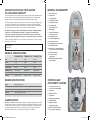
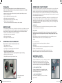
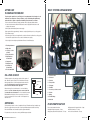
ROUTINE MAINTENANCE
To ensure long service life and to maintain the tender in a safe and reliable condition
please follow these routine maintenance instructions. Williams cannot accept any
responsibility for damage or injury resulting from incorrect maintenance or improper
adjustment carried out by the owner.
OWNERS
HANDBOOK
1. Re-pack shaft seal approximately every 10 hours of operation with Quicksilver marine 2-4-C
grease, or equivalent high temperature, high speed bearing grease. As a guide use two pumps of
the grease gun supplied with the tender. Take care not to over-pressure seals and wipe away
excess grease.
2. Check engine oil level.
3. Check coolant level.
4. Flush open loop cooling system.
5. Apply a good quality marine grease containing Teflon (e.g. Quicksilver 101) to all control cables
both under the helm and at the pump.
6. Check bilges for water ingress, oil or fuel contamination.
7. Lightly grease the extending running light pole using white grease or similar.
8. Check condition of the 2 pump anodes.
9. Loss of tube pressure over 24 hours is not unusual. Temperature and atmospheric pressure will
affect tube pressures. Check pressures regularly.
WINTER STORAGE
Refer to the Williams service manual for winterisation procedures.
SUPPLYING DEALER STAMP:
LIMITED WARRANTY
This boat is intended for pleasure use only. It is covered by a limited warranty which applies for defects and flaws, which may occur,
despite normal use and regular maintenance, for a period of 2 years for hull and 3 years for tubes from the date of registration.
Full warranty terms are contained within the Williams service manual.
Williams Performance Tenders Ltd.
Vogue Business Park, Berinsfield, Oxfordshire, OX10 7LN, United Kingdom
T: +44(0) 1865 341134 F: +44(0) 1865 341234 W: www.williamsmarine.com
9910_WILLIAMS MANUAL REPRINT.indd 1-2
27/11/06 17:10:10
CONGRATULATIONS ON YOUR CHOICE
OF A WILLIAMS TURBOJET
GENERAL ARRANGEMENT
1.
Water tight storage
This owner’s handbook has been compiled to help you operate your Turbojet with safety and pleasure.
It contains details of the boat and equipment fitted, together with information on its operation and
maintenance. Please read it carefully, and familiarize yourself with the boat before using it.
2.
Mooring cleat
3.
Front lifting points
4.
Fuel filler (under seat)
The Williams Turbojet uses water jet propulsion. If this is your first boat, or you are changing to a type
of boat you are not familiar with, for your own safety, please ensure that you obtain handling and
operating experience before assuming command of the boat. Your dealer, national sailing federation
or yacht club will be pleased to advise you of sea schools, or competent instructors.
5.
Throttle/shift control
6.
Rear lifting points
7.
Ski tow (below seat)
8.
Running light
9.
Key switch and battery
isolator (below seat)
The Turbojet is a high performance boat. Williams recommends a minimum standard
of RYA level 2 or ICC (International certificate of competency) is attained by the
operator prior to taking control of this boat. This manual assumes the operator has
acquired this standard of qualification and possesses knowledge of basic seamanship.
Please keep this handbook in a secure place and hand it to the new owner
when you sell the boat.
1
2
3
16
3
16
15
10. Port navigation light
11. Starboard navigation light
12. Storage (below seat)
12
4
13. 12v auxiliary power/charge socket
14. CE certification plate
Hull Identification
Number (HIN):
10
15. Drain plugs (one in forward footwell
and one in each of the rear footwells)
GENERAL SPECIFICATIONS
16. Tube inflation valves
TURBOJET 385
TURBOJET 325
TURBOJET 285
LOA
3.85m
3.30m
2.85m
Beam
1.74m
1.68m
1.64m
Dry weight
340kg
296kg
286kg
Overall height
910mm
910mm
910mm
Maximum speed
48mph-52mph
48mph-52mph
48mph-52mph
Fuel capacity
60 Litres
41 Litres
41 Litres
Seating
5 Adults + 1 Child
4 Adults + 1 Child
3 Adults + 1 Child
17. Over pressure valve
(where fitted)
16
6
6
9
14
17
13
7
18
Weber MPE 750cc turbo
Maximum power
104hp/76kW at 7300rpm
1.
Tachometer and hour meter
Fuel
Premium unleaded gasoline 92-98 RON
2.
Low oil pressure warning light
Oil grade
0W40 to 15W50 fully synthetic
3.
Fuel gauge
Oil capacity
3.5 litres maximum
4.
Bilge pump switch
5.
Speedometer
6.
Exhaust temperature light
7.
Navigation lights
8.
Bilge blower switch
9.
ECU malfunction light
Category C – “inshore”: Craft designed for voyages in coastal waters, large bays, estuaries, lakes
and rivers, where conditions up to and including wind force 6 and significant wave heights up to and
including 2m may be experienced. This boat complies with ISO 6185-3. The HIN is located above
jet nozzle below transom step. Record it in the service handbook. The CE plate is located in the
starboard footwell. The CE plate is the certification to European Directive 94/25/CE.
16
8
Engine
CLASSIFICATION
5
18. Hull Identification Number (HIN)
(under platform)
CONTROLS AND
INSTRUMENT CLUSTER
ENGINE SPECIFICATIONS
9910_WILLIAMS MANUAL REPRINT.indd 3-4
11
3
1
5
2
6
8
9
11
7
4
10
10. Engine safety lanyard switch
11. Fuses (engine compartment)
27/11/06 17:10:19
FUELLING
OPERATING YOUR TENDER
As part of its pre-delivery inspection your new Turbojet has been run and
drained of fuel. When refuelling use only premium unleaded gasoline 92-98 RON.
This boat uses a water-jet propulsion system and has unique characteristics in steering. The throttle
produces thrust from the jet pump, the directional control is provided by opening the throttle and
turning the wheel in the direction of your turn. High thrust will turn the boat sharply; low thrust will
produce less turning force. There is no rudder, so while underway there is no steering without thrust.
l Ensure ignition is in OFF position.
l Remove seat cushion to expose filler cap. A key is provided to assist in filler cap removal.
After running tender at high speeds it is important to allow engine to idle for a minimum of one minute
before switching off to allow turbo to cool.
l Re-fuel in a ventilated area.
l Do not overfill the tank; be careful not to spill fuel.
l Tighten fuel cap securely after re-fuelling.
l Open engine hatch and inspect bilges after re-fuelling.
l The filler cap has an integral breather.
Do NOT hose around the fuel filler area as water may enter the fuel tank.
If weed or debris gets caught in the jet unit during use, cavitation can occur, causing a decrease in
forward thrust. If this condition is allowed to continue the engine may overheat resulting in serious
damage. If there is any sign of debris, weeds etc. blocking the jet, remove the boat from the water.
Switch off battery isolator and remove all debris from around the jet unit. In case of difficulty consult
your Williams approved dealer.
MOORING
BEFORE USE
To ensure maximum performance from your Turbojet the tubes should be evenly inflated to a pressure
of 2.9psi (0.2bar). Failure to observe this will compromise the sea-keeping ability and water tight
integrity of the boat. Inflation valves are fitted with quarter-turn locks to enable rapid deflation.
l Set valves to shut and inflate tubes evenly to 2.9psi (0.2bar).
l Check bilge for fuel or water contamination.
l Tighten footwell drain plugs.
l Check engine cover latches are secure.
STARTING YOUR TURBOJET
Ensure boat is in a depth of at least 0.5m/2ft of water.
Do not leave the Turbojet moored for extended periods as this may result in an accumulation
of marine growth and a loss of performance.
BEACHING
DO NOT operate in less than 0.5m/2ft of water as debris may enter the jet unit. DO NOT
drive turbojet onto beach. Stop engine before beaching as damage to pump/engine cooling
may occur.
After beaching move boat into deeper water and tilt from side to side several times to remove
sand from intake area – failure to do so could cause damage to jet unit.
TRIM
Do not overload the boat.
At all speeds be aware of trim and keep weight evenly distributed.
1. Turn on battery isolator.
GENERAL
2. Run bilge blower for one minute.
Operate the boat with due care and at a speed appropriate to the sea conditions.
Be aware of local laws and restrictions.
Always carry out a visual check of the boat and its components prior to use.
3. Secure any loose ropes that could get sucked into jet unit.
4. Ensure shift lever is in central position.
5. Connect safety lanyard to switch.
ALWAYS attach yourself to the safety lanyard when engine is running.
6. Turn ignition key until engine starts.
7. Engine RPM will automatically be limited until warm.
Adhere to the maintenance/service schedule as detailed in the service manual.
WARNING LIGHTS
1. EXHAUST TEMPERATURE
This lamp will illuminate if the open loop coolant supply is restricted.
After restarting a hot engine it is normal for the lamp to stay
on for up to 30 seconds. If the lamp stays on for longer than 30
seconds or comes on when engine is above idle, STOP the engine
and check for restriction in coolant system (debris in pump/pipes).
2
2. ECU MALFUNCTION
1
This lamp will illuminate if there is a fault with the engine
management system. If this occurs STOP the engine and
refer to Williams approved dealer.
3
1
2
3. LOW OIL PRESSURE
1. Battery isolator switch
2. Key switch
9910_WILLIAMS MANUAL REPRINT.indd 5-6
If this illuminates, STOP the engine and refer to Williams
approved dealer.
27/11/06 17:10:22
BOAT SYSTEM ARRANGEMENT
AFTER USE:
FLUSHING PROCEDURE
1
To prolong the engine life of your Turbojet it is very important to flush engine of salt
water after use and prior to storage. Failure to carry out flushing will significantly
reduce the life of engine components. DO NOT operate throttle out of water.
2
3
1. Remove the boat from the water everyday and wash entire boat/jet pump with fresh water.
2. Connect a fresh water hose fitted with the female connector supplied with the tender to the
coupling on the transom.
3. Start engine and immediately turn on water supply.
4. Run engine at idle for approximately 1 minute to completely flush the open loop cooling system.
4
5. Turn off water supply.
6. Allow the engine to run for no longer than 10 seconds for all water to exit from the cooling system,
then turn off the engine. Remove hose connector from transom coupling.
10
7. Check bilge of boat and dry any residual water. Remove footwell drain plugs.
5
1. Flushing attachment
2. Bilge outlet
9
4
3. Open loop coolant
overflow
1
6
2
4. Fuel spill overflow
8
3
7
5. Right hand rear
footwell drain
6. Pump anode
7. Ride plate anode
8. Left hand rear
footwell drain
5
9
8
9. Front footwell drain
7
6
11
OIL LEVEL CHECK
The Weber engine is a ‘dry sump’ type engine, with a separate oil
tank. When the engine is started oil is evacuated from the sump.
After the engine has run, oil will slowly return from the tank to the
sump. The engine must be run for at least 20 seconds
before a level is indicated on the dip-stick.
When checking oil level out of the water, i.e. on a level bathing
platform or trailer the boat must be run for no more than 20
seconds without coolant water. The oil level should be between
MIN and MAX on the dipstick. Do not screw in cap to check level.
Use the correct grade of oil. Do not overfill – oil will expand to top
mark when hot.
1. Fuel level sender
2. Fuel return
OVERFILLED
3. Fuel feed
MAX
5. Fuel pump
0.5 LITRES
7. Closed loop coolant reservoir
8. Oil tank
MIN
The important post run-in 1st service is required at 25 hours. Thereafter servicing is required every
50 hours or yearly whichever comes first. Consult your Williams approved dealer for servicing.
Refer to the Williams service manual for periodic engine maintenance.
9910_WILLIAMS MANUAL REPRINT.indd 7-8
11
6. Fuel filter
SERVICING
For parts and accessories please contact your Williams approved dealer.
4. Fuel pre-filter
9. Battery
10. Throttle linkage
11. Shaft seal
FUSE IDENTIFICATION
Fuses located under helm station.
l Bilge pump switch: green/red wire – 5 amp
l Navigation lights: orange wire – 5 amp
l Blower: brown wire – 7.5 amp
l Bilge pump float switch: red/blue wire – 7.5 amp
l 12v socket: red/white wire – 25 amp
27/11/06 17:10:26