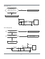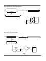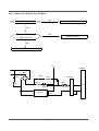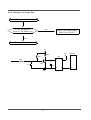
1
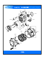
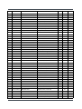
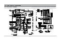
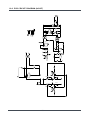
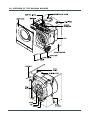
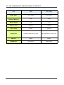
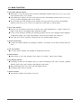
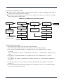
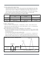
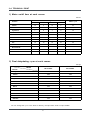
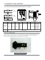
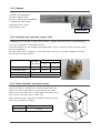
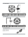
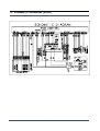
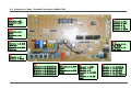
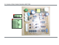
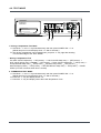
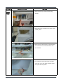
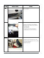
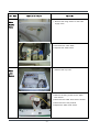
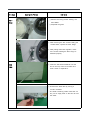
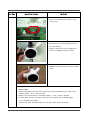
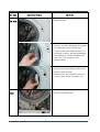
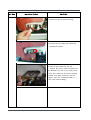
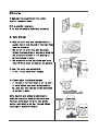
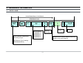
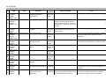
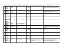
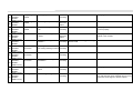
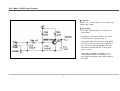
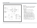
WF-F125NC/YLW
WF-F105NV/YLW
BASIC MODEL
WF-F125AC/YLP
SERVICE
F125NC
Manual
THE FEATURE OF PRODUCT
1. Silver Wash Ag+
2. Mixed Load
3. Calm Wash
4. Child Lock
5. Quick Wash
Refer to the service manual in the itself (http://itself.sec.samsung.co.kr/) for the more information.
F0125
R0019
C0002
C0075
C0115
C0075
C0043
A0128
C0008
R0124
U0012
C0044
C0058
D0003
R0036
D0081
A0328
D0061
D0112
D0046
D0075
44
U0355
I0043
U0010
U0095
U0307
R0158
U0015
U0033
U0355
U0355
U0328
U0038
U0029
R0030
R0001
U0035
D0048
U0030
U0018
45
U0016
U0013
P0001
W0002
W0018
W0004
A0115
W0001
R0135
Y0040
R0159
R0158
R0148
R0158
R0021
R0159
A0025
I0043
P0030
C0117
I0041
I0022
F0027
A0114
U0133
U0133
B0070
A0006
J0013
46
I0003
7-2. PARTS LIST
NO.
CODE NO.
A0004
DC63-00609A
A0006
DC63-00608A
A0025
DC97-02106A
A0034
DC60-40146A
A0043
DESCRIPTION
COVER-FILTER
SPECIFICATION
QTY SA/SNA REMARK
F125AV-B145AV,ABS
1
SA
COVER-FRONT(L)
F125AV-B145AV,ABS
1
SA
ASSY-FIXER TUB
S1005J,SLIM-PJT
5
SA
BOLT-SPANER
OD36,T2.5,L52,FE,FZY,P
1
SA
DC61-10688A
CAP-FIXER
SWF-P12,PP(TB53),WHT,
5
SA
A0043
DC61-10688A
CAP-FIXER
SWF-P12,PP(TB53),WHT,
1
SA
A0067
DC69-00646A
CUSHION-CORNER
Q1636GW/XEU,PS-FOAM
2
SA
A0114
DC64-00434A
SHUTTER
F1215J/F-PJT,PP,WHT
1
SA
A0115
DC61-60180A
SLEEVE-PLUG
NYLON#6,SEW-720DR,NTR
4
SA
A0128
DC64-01018A
WINDOW-PANEL
T2-PJT,PC,W25,L54,TRP
1
SNA
A0198
6902-000215
BAG SHEET
NITRON/HDPE,T0.5/T0.012,W1000,
2
SA
A0198
6902-000304
BAG PE
LDPE,T0.05,L230,W180,TRP,8,2,PE M
1
SA
A0198
DC69-30007G
BAG PE
HDPE-FILM,T0.015,L360,W230,NO
1
SA
A0198
DC69-30007K
BAG PE
HDPE,T0.03,W700,L700,4
1
SA
A0198
DC69-30007U
BAG PE
HDPE,T0.03,L450/C20,W330,NO_P
1
SA
A0328
DC64-01011A
PANEL-DRAWER
WF-B125,ABS,WHT
1
SNA
A0362
DC61-40081A
HOLDER-WIRE
DAWH-2NC,NYLON66,NTR
6
SA
B0070
DC97-02079D
ASSY-LEG
SBP2,SD455,SD405,FLANG TYPE/25M
4
SA
C0002
DC97-09899V
ASSY-PANEL CONTROL
WF-F125NC/YLW,CR PLAT
1
SA
C0008
DC64-01012A
WINDOW-ENCODER
WF-B125A,PC,TRP(2
1
SNA
C0043
DC64-01013C
BUTTON-PUSH(F)
WF-J145NC/YLP(T2-PJT,ABS,
1
SA
C0044
DC64-01014A
BUTTON-PUSH(P)
WF-B125,ABS,SNOW-WHT,
1
SNA
C0058
DC64-00653A
DOOR-LOCK S/W
DA,PA6-G,H82,W50,BLK,2
1
SA
C0075
DC64-00942A
KNOB-ENCODER
T-PJT,ABS(HG-0760),
1
SA
C0075
DC64-01015A
BUTTON-ENCODER
WF-B125,ABS,WTH,1200R
1
SA
C0115
MFS-T2F12AB-00
ASSY PCB PARTS(M)
MFS-T2F12AB-
1
SA
C0117
MES-AG2MOD-S0
ASSY PCB PARTS(S)
MES-AG2MOD-S
1
SA
D0003
DC61-00932A
HINGE-DOOR
Q1636GW/XEU,ZNDC,TS
1
SA
D0046
DC97-05111A
ASSY-LEVER DOOR
Q1636GW/XEU,TS-2 PJT
1
SA
D0048
DC61-00933A
BRACKET-HINGE
Q1636GW/XEU,SBHG,T
1
SA
D0061
DC64-00920A
DOOR-GLASS
R831,GLASS,NTR,CKD /C
1
SA
D0072
DC61-00891A
GUIDE-HINGE
HAUZEN(DOM),POM,WHT,HI
2
SA
D0075
DC64-00773D
HANDLE-DOOR
WF-F125AC,ABS,CR-COA
1
SA
D0076
DC64-00564A
HANDLE-PIN
Q1636GW/XEU,STS,TS-
2
SA
D0081
DC61-01144A
HOLDER-GLASS
SEW-3HR109BT,PP(TB53)
1
SA
D0112
DC63-00506C
COVER-DOOR
WF-F125AC,ABS,CR-CO
1
SA
F0027
DC99-00620A
ASSY-PAINT FRAME
WF-F125AV,AG+/T1.0/NEAT
1
SA
F0064
DC97-09198C
ASSY-FRAME FRONT
T-PJT,NEAT-WHT
1
SA
F0065
DC97-05134C
ASSY-FRAME PLATE(U)
WF-B125AV/YLP,T-PJT/
1
SA
F0125
DC61-01397A
FRAME-PLATE(U)
T-PJT,EGI,NTR,T0.8,
1
SNA
I0003
DC62-10289C
HOSE-WATER(C)
RUSSIA,PVC+NYLON,ID10.3,
1
SA
I0022
DC97-00139E
ASSY-HOSE DRAIN(O)
SB-PJT,PP/L1770/CHINA
1
SA
I0030
DC62-10278A
HOSE-HANGER
PP(JS20),NTR
1
SA
I0041
DC67-00107A
HOSE-PRESSURE
S821,PE-BLOW,ID13.2,OD6.2,
1
SNA
47
NO.
CODE NO.
DESCRIPTION
I0043
DC62-10303A
HOSE-AIR
I0043
DC62-10272D
I0043
DC62-10272B
J0013
SPECIFICATION
QTY
SA/SNA
REMARK
EPDM,ID24,L130,BLK,SWF-P1
1
SA
HOSE-AIR
S621,PVC,ID4.5,L520,NTR
1
SNA
HOSE-AIR
F1035SA/F1235SA,PVC,ID4.5,L
1
SNA
DC96-00859A
ASSY-PUMP DRAIN
R1245A/XSC,220V~240V/50H
1
SA
J0019
DC61-10652C
CASE-PUMP
PP(5113MF6),SWT50B1P,GRY
1
SA
J0024
DC62-00187A
SEAL-WASHER
SW80ASPIW/YMI,NBR,BLK,
1
SA
J0025
DC31-00056A
PUMP-DRAIN
220~240V,50Hz,30W/3000RPM
1
SA
P0001
DC97-09919A
ASSY-COVER TOP
T2-PJT/WF-F125NC,WOOD/NEA
1
SA
P0030
DC32-30006P
SENSOR PRESSURE
DN-S14(P1291),TERMINAL-T
1
SNA
P0082
DC97-05973A
ASSY-HOSE PRESSURE
5.2kg/SD455/SD405,PVC
1
SA
R0001
DC97-01463J
ASSY-DRUM
F-PJT/SD-PJT/LIFTER,STS430/FIX
1
SA
R0019
DC97-09221D
ASSY-HOUSING DRAWER
WF-F125AC/YLP,AG+/2W
1
SA
R0019
DC97-02132F
ASSY-HOUSING DRAWER
WF-R125AC,TROIKA-PJT
1
SA
R0021
DC97-06842A
ASSY-GUIDE WATER
F1235SA,AG+ASSY
1
SA
R0025
DC97-09695A
ASSY-PANEL DRAWER
WF-J145NC/YLP/T2-PJT,7
1
SA
R0027
DC97-00731A
ASSY-SENSOR PRESSURE
P1091,S-PRE+BRAKET+
1
SA
R0030
DC91-12078A
ASSY-WIRE DIAPHRAGM
SWF-P12,FRAME-FRONT
1
SA
R0036
DC61-01395A
BODY-DRAWER
WF-R125,PP,NTR,5.2KG
1
SA
R0047
DC67-00114A
CAP-FILTER
SW80ASPIW/YMI,P.P,BLK
1
SA
R0096
DC63-00143A
HOUSING-DRAWER(L)
PP(TB-53),SL-600,WHT
1
SA
R0124
DC61-01417A
STOPPER-DRAWER
TROIKA PJT 5.2kg,PP,T2.5,
1
SNA
R0147
6011-001421
BOLT-FLANGE
M7,L61(29.4),ZPC(YEL),SWRCH1
5
SA
R0148
DC61-40345A
BRACKET-PRESSURE
GI or GA,SWK-P12,T1.0
1
SNA
R0154
DC63-10060B
SPONGE-HARNESS
CHINA,PU-FOAM,T10,W80,L50
1
SA
R0154
DC63-10002M
SPONGE-HARNESS
T5,W60,L100,PU-FOAM,
1
SA
R0158
DC62-10305A
HOSE-DRAWER TUB
EPDM,ID35,L158,BLK
R0158
DC67-00051D
HOSE-DRAWER
S1093~S6093,EPDM,BLK
1
SA
0.42
SA
R0158
DC67-00051G
HOSE-DRAWER
F1045A,EPDM,ID10,OD16,BL
1
SA
R0159
DC61-01279A
R0159
DC61-01280A
SPRING-HANGER
5.2KG(F631/F831),HSWR,CD2.
2
SA
SPRING-HANGER
5.2KG(F631/F831),HSWR,CD2.
2
SA
R0160
DC61-70184A
SPRING-CLIP
XQB46-71,HSWR,
2
SA
U0003
DC60-60044A
WASHER-PLAIN
ID10.5,OD30,T3,STS304
2
SA
U0003
DC60-60044B
WASHER-PLAIN
SBC,ID8.4,OD30,T3
5
SA
U0005
DC60-60040A
WASHER-NYLON
ID10.5,OD32,T2,PBSP-1/2
5
SA
U0010
DC66-10176B
PULLEY
ALDC,D297,P1291,ID12.5
1
SA
U0012
DC61-00856A
BRACKET-HEATER
SB-PJT,STS430
1
SNA
U0013
DC97-00214K
ASSY-TUB BACK
SWF-P8/P6091,LOW-RPM/NO.3
1
SA
U0015
DC31-00002H
MOTOR-DRUM
HXGP2I,S803J,50HZ,LOW-R
1
SA
U0016
DC62-00007A
SEAL-OIL
NBR(SD25),BLK,P6091/NBU
1
SA
U0018
DC47-00006B
HEATER
KAWAI,P-SLIM MODEL,SUS316L,23
1
SA
U0023
DC61-00201A
BRACKET-NUT
SBHG-R,P1291,T3,NO-PAI
1
SA
U0023
DC61-00201A
BRACKET-NUT
SBHG-R,P1291,T3,NO-PAI
1
SA
U0023
DC61-40348B
BRACKET-NUT
SBHG-R,P1291,T3,NO-PAI
2
SA
U0023
DC61-40348B
BRACKET-NUT
SBHG-R,P1291,T3,NO-PAI
2
SA
U0026
DC97-02138E
ASSY-TUB FRONT
SD455/5.2KG(FRONT),DIAPHR
1
SA
48
NO.
CODE NO.
DESCRIPTION
SPECIFICATION
QTY
SA/SNA REMARK
U0029
DC61-20219E
DOOR-DIAPHRAGM
SEW-HW107,EPDM,GR
1
SA
U0030
DC61-00365B
TUB-FRONT
SL-600,FRPP(GR15%)SAMBAK
1
SNA
U0033
DC62-00121A
HOSE-FILTER TUB
S1005J,EPDM,ID65
1
SA
U0035
DC62-20311A
VANE-CHECK
SWF-P12,EPDM,BLK,
1
SNA
U0038
DC91-12077A
ASSY-CLAMP DIAPHGRAM
SWF-P12,TUB
1
SA
U0082
DC62-00116A
FILTER-NET
P1205J,EPDM+STS304,OD25,ID9
1
SA
U0095
6602-001072
BELT-TIMING GEAR
POLYURETHAN,L1270,J5,ME
1
SA
U0133
DC66-00334A
DAMPER-SHOCK
Q1636GW/XEU,L197.5,
2
SA
U0307
DC61-00041A
CUSHION-MOTOR
SWF-6V,BUTYL,ID16/OD
1
SA
U0320
6011-001448
BOLT-HEX
M8,L170(25),ZPC(YEL),SWRCH18A,W
1
SA
U0320
DC60-40141A
BOLT-HEX
SM10C/DAMPER,HEX,M8,L66,ZPC2(
2
SA
U0320
6011-001452
BOLT-HEX
M10,L20,ZPC(YEL),SWCH10AK,ASSY(
1
SA
U0320
6011-001447
BOLT-HEX
M8,L123(25),ZPC(YEL),SWRCH18A,W
1
SA
U0320
DC60-40144A
BOLT-HEX
M10,L41,ZPC2(YEL),SM10C/DAMPER
2
SA
U0328
DC62-40183A
PACKING-TUB
SWF-P12,EPDM,BLK
1
SA
U0353
DC61-60359E
CLAMPER HOSE
F1235AS/F1035AS,ID7.8,Y
1
SA
U0353
DC61-60359E
CLAMPER HOSE
F1235AS/F1035AS,ID7.8,Y
1
SA
U0353
DC61-60497A
CLAMPER HOSE
SWF-P12,HSWR,ID70/OD75.8,
1
SA
U0353
DC61-00118A
CLAMPER HOSE
P1291,LYLON6/6,ID27,OD30,
1
SA
U0353
DC61-00133A
CLAMPER HOSE
P1291,PP(BJ-730),ID24.5,OD2
1
SA
U0354
DC97-06393J
ASSY-SEMI TUB DRUM
WF-F125AC/YLP,SSEC
1
SA
U0355
DC67-00038A
WEIGHT-BALANCER
F-PJT(40CM),CONCREET
1
SA
U0355
DC67-00042C
WEIGHT-BALANCER
F,R MODEL ETC.,Concrete,
1
SA
U0359
DC62-00066A
FILTER-CASE
PP,BLK/SW90V2
1
SA
U0360
DC61-60499B
CLIP-TUB
HSWR,P1291,NO/PAINT,
6
SA
U0360
DC61-60520A
CLIP-TUB
SK5,SWF-P12,PLATE-TYPE,
2
SA
V0016
DC68-20361A
LABEL-PRICE
DOM_ALL,MOJOGI,W70,L20
1
SA
W0001
DC96-00990A
ASSY-WIRE HARNESS
TROIKA-PJT,SUB/WIRE (R
1
SA
W0002
DC96-00146A
asSY POWER CORD
UCP2,250V/16A,
1
SA
W0004
DC96-00947A
ASSY-M.WIRE HARNESS
WF-F85A,TROIKA-PJT/A
1
SA
W0032
DC62-00024F
VALVE-WATER
B1215J,NYLON66/250TRMN,N
1
SA
Y0040
DC29-00006A
FILTER-EMI
DFC-2712R,P/PV/SLIM,250V,12A,
1
SA
Z0006
DC97-02412A
ASSY-BOLT
SWF-P12,MOTOR, M8*L62
1
SA
Z0006
DC97-02412H
ASSY-BOLT
Q1657
1
SA
Z0006
DC97-06159B
ASSY-BOLT
SCD-PJT
1
SA
DC63-00651A
COVER-HEATER
Q1657TGW/XEU,GI,T0.4,
1
SA
DC68-20436A
LABEL-PACKING
ART-PAPER,W110,L230,STANDA
1
SA
DC72-00038A
SPONGE-FRAME
TROIKA-PJT,PU-FOAM,T13,W1
1
SA
49
10. PCB CIRCUIT DIAGRAM
This Document can not be used without Samsung's authorization.
VAREF
6
5
7533
CE5
1uF
4.7K
ISP_TEST
8
R49
150
KID65003AP
G
R58
620
620OHM 1W X 4
9
22
23
DGND
2
3
4
24
51
26
16
45
26
16
POWER_RELAY
45
DIGIT-LED
26
CW/CCW
12
11
10
5
6
7
27
28
29
27
25
37
27
HIGH SPEED
30
46
46
G
VCC
9
C28
10nF
MT1
G
2
3
4
5
6
34
35
F
48
49
G
50
22
FTR-F3AA012E
R5
R4
R3
R7
R6
R2
R1
4.7K
4.7K
4.7K
4.7K
4.7K
LED9
LED15
LED21
GND VCC
LED4
LED10
LED16
LED22
LED5
LED11
LED17
LED23
CSQ-4744G
4
330 R9
3
2
9
KID65003AP
1
9
10
11
12
LED25
LED26
LED30
LED29
LED27
LED31
LED39
LED37
LED35
LED33
LED34
LED36
LED38
LED41
LED43
LED45
LED47
LED46
LED44
LED42
LED6
LED12
LED18
LED24
LED28
LED32
LED48
DGND
1N4148
+5V
270KOHM 1/2W X 2
1N4007
D30
D29
R42
33K
CE8
10uF
C19
100nF
9
BLUE_LED
BLUE_LED
330 R71
BLUE_LED
BLUE_LED
IC2
38
39
40
41
42
1
18
2
17
3
16
4
15
5
14
6
13
7
12
8
43
9
+12V
11
VCC
GND
10
DGND
KID65783AP
EEPROM2
2
XIN
3
XOUT
DIAL-2
17
17
DIAL-B
10
10
1
2
3
10K
R30
D26
5
D28
6
7
8
R47
4.7K
CE9
10uF
R64
27K
1K R51
R66
4.7K
DGND
TACHO
R68 1K
2
1
MMBT3904
B
A
CN10
C29
100nF
DGND
DGND
52
C32
100nF
DGND
D16
D15
D6
D8
D13
D4
AG_KIT CURCIRT
DGND
+5V
R69
4.7K
24LC04B
SDA
VSS
SCL
A2
WP
A1
VCC
A0
4
3
2
1
R67
4.7K
R65 1K
10
TR2
JOG1
R62 1K
17
JES1424GS
DGND
5
CN7
5
DGND
IC5
+5V
1K R35
4
R21 4.7K
R24 100
DGND
10K
R29
52
4
55
+5V
DGND
16MHZ
+5V
C21
100nF
3
21_1
PWM_AG
AG-IL
EEPROM1
RESO1
53
DGND
2
AG-IH 20_1
6
R20 4.7K
R23 100
F3
flat_wire_2x10p
52
1
AG SIG-B 15_1
AG SIG-A
15 AG SIG-B
53
CN8
55
D10
34
35
1N4148 X 8
55
R60
4.7K
AG SIG-A 14_1
C17
14
15
20
21
OPTION
4.7nF
56
14
DIGIT-LED
DIGIT-LED
D2
35
KEY_SCAN 54
57
57
56
D3
34
D32
BUZZER
33
D31
DGND
DOOR-LOCK
R59
4.7K
31
32
33 BIMETAL(LOCK)
1N4148 X 8
DOOR-UNLOCK
29
30
C5
+5V
Door_Com
32
SW8
+5V
31
SW7
15
16
30
SW6
25
13
14
15_1
16_1
29
PRE
D_PUMP
D9
C7
1nF
MAIN(COLD)
D5
BUZZER
D7
AG-IL
47
53
52
DGND
G
D_CHK
GND VCC
330 R55
36
37
DGND
C10
100nF
10
C16
CE6
10uF
11
7
4.7nF
33K
R34
R36
47K
21
BUZZER1 WILL
F
LED40
12
6
62
63
100nF
D25
330 R43
DGND
THERMISTOR
48 W/L SENSOR
R72 1K
1N4148
1N4007
RELAY4
SMWB250-05WHT
R32
270K
22
47
R75
220
D27
1N4148
R31
270K
R73 2.2K
CE10
47uF
D24
270KOHM 1/2W X 2
63
13
8
59
60
61
HOT
48
21
RELAY3
OMIH_SH_112L
+5V
PWM_AG
TACHO
14_1
20_1
21_1
TR3
+12V
2
8
62
14
4
4.7nF
7
CN4
61
C9
D22
6
60
SW5
1
5
5
6
59
SW4
RTE24012
4
58
15
3
5
SW3
C1
300OHM 2W
3
100nF
R74
4.7K
1N4148
100 R17
43
39
40
41
42
43
58
4.7nF
CM3
100OHM 2W
+12V
R48 300
KSA928A-Y
NV2-08730
42
DIGIT-LED
DGND
DGND
180 R15
100nF
COIL1
BD1
2 B
41
16
2
+5V
100nF
1 A
CN1
40
38
1
DGND
180OHM 2W
TRIAC1
SM10LZ47
39
45
46
C15
100nF
+12V
+12V
CM1
IC6
KID65003AP
44
SCAN-LED KEY
24 W_HEATER
44
28
DGND
1N4148
D34
VAR1
SCAN-LED KEY
DIGIT-LED
38
50 DOOR-SIG IN
F1
flat_wire_2x10p
RELAY6
GRN
16
13
6
24
44
28
DGND
36
36
50
10K
47 R28
14D561K
SMW420-06
15
1
64
12
11
RELAY7
DGND
37
13
D12
THER
25 PWM_AG
DGND
15
14
13
1N4148
D35
R50 1K
THER
31
32
33
FTR-F3AA012E
2
16_1
F2
flat_wire_2x10p
8
1
10
7
KID65003AP
+5V
R46
47K
14
2
5
330 R13
D14
CN9
R61
620
MT2
SM2LZ47 TRIAC5
GND
16
10nF
7
8
R40
3
51
SW2
C30
5
6
EX_INT
GND
8
1
IC9
R57
620
C26
10nF
MT1
SM2LZ47 TRIAC4
R70
150
SMW420A-08
SMWB250-04VWHT
G
DGND
IC7
MT2
2
3
4
270K
LED3
6
8
DGND
C14
10nF
15
14
13
10nF
1
R39
13
8
SW1
R63
150
C27
R56
620
C24
10nF
MT1
SM2LZ47 TRIAC3
270K
LED20
23
C6
R54
150
MT2
2
3
4
4
C18
10nF
zero cross
49 DOOR-SIG IN
16
VCC
9
C20
10nF
MT1
10nF
1
LED14
RESET
DIGIT-LED SCAN-LED KEY
OJ2
JUMP
CC1
680nF
C25
CN6
23
Motor Controll
MR1000 51
TACHO
9
9
49
SM2LZ47 TRIAC2
C23
100nF
LED8
330 R14
1N4148
D33
MT2
CE7
10uF
12
330 R12
FTR-F3AA012E
RELAY5
10nF
R45
10K
LED2
7
DGND
C22
4
LED19
7
D1
1N4148
3
LED13
DGND
RY?
OMIF-S-112LM
1
11
5
CN5
OUT
GND
C12
100nF
6
330 R8
1
100nF
IN
2
10K
R37
IC8
R41
47K
CN2
ISP_RX
4
3
TR1
MMBT3904
D11
1N4148
11
4
R44
1K
+12V
RY?
OMIF-S-112LM
+5V
ISP_TX
LED7
330 R10
R33
R52 1K
EX_INT
C4
10nF
10
330 R11
12
C13
PC2
LTV814
DGND
7
DGND
VSS
10K
R38
R53
4.7K
58
59
60
VDD
1
+5V
DSP1
LED1
330OHM 1/2W X 10
IC1
61
62
63
THERMISTOR
ZD1
57
4.7K
4.7K
20
AVDD
18
5
R16 100K
20
C11
CE4
470uF
C8
R27
100nF
CE3
100K
S4
100nF
UF4007
2200u
19
DGND
100
R22 100K
1
AG-IH
OUT
GND
MTZJ11B
WHT
YDW236-01BLK
IN
R26
100
8
7
5
PC1
LTV817B
R25
C2
100nF
KA7805A
IC4
DGND
DR
BYP S3
1
D18
D20
1N4007 X 4
+12V
S1
VAR3
S2
270M
CE2
470uF
D23 UF4007
EN
PTC?
3
CN3 14D911D 14D182
100nF
CM2
D21
IC3
TNY266P
20D561
VAR4
JUMP
3
VAR2
CE1
10uF
+5V
+5V
CHIP X 7
MICOM1
TMP86FS49FG
+12V
C3
2.2NF
4
L1
1
2
LVT1
T-PJT
R19
100K
2
90019WS-03WHT
D_CHK
D17
D19
10-1. PCB CIRCUIT DIAGRAM
(JOG DIAL CURCIRT)
10-2. PCB CIRCUIT DIAGRAM (AG-KIT)
CN1
90019WS-03WHT
C6
10nF
D5
R23
100K
D2
C8
2.2NF
6
7
8
LVT1
EE1616-H
3
1
R28
47
5
2
4
PC5
LTV817B
1
2
UF4007
D3
D1
UF4007
18V
R37
120OHM
CGND
CGND
CGND
CE10
47uF
CE13
470uF
R33
100
R36
220
IC4
KA7818
CGND
4
2
1
CGND
3
PC6
LTV817B
R17
10K
ZD3
1N4751
18V
CE11
1uF
4.7K
R30
CGND
+12V
CE8
10uF
4.7K
R31
CGND
1K
R7
DGND
18V
CE9
10uF
Signal_A
R3
4.7K
1K
R1
R24
20K
DGND
1
2
18V
3
4
LTV817B
PC1
IC2
LM393
CGND
R9
4.7K
4.7K
R11
R16
4.7K
4.7K
R13
+12V
TR1
TR5
Ag_B
CGND
4.7K
R14
R12
4.7K
4.7K
R15
R10
4.7K
R27
27
+12V
CGND
C7
100nF
TR6
Ag_A
TR4
KSA928A-Y
KSA928A-Y
KSA928A-Y
KSA928A-Y
D4
CE4
10uF
100
R20
4
3
ZD2
1N4751
IC1
KA2904
CGND
7
D7
C1
100nF
1
Signal_B
1
2
CGND
LTV817B
4
2
1
PC3
3
DGND
1K
R6
Signal_B
53
+IB
5
GND
TNY266P
CN2
SMWB250-09WHT
5
4
3
2
Signal_A
PC4
LTV817B
4
3
8
8
D6
IC3
DGND
7
IH
+IB
5
GND
6
8
9
DGND
R38
1K
OB
7
VCC
6
-IB
4
+IA
3
-IA
2
OA
1
OB
6
-IB
4
+IA
3
-IA
2
VCC
OA
1
UF4007
DR
EN
7
2
5
S2
4
S4
S1
3
8
BYP S3
1
1N4007
1N4007
1N4007
1N4007
L1
JUMP
PTC1
270M
2. THE FEATURE OF PRODUCT
2-1. SPECIFICATIONS
FRONT LOADING TYPE
WASH TYPE
NET
W 598mm X D 404mm X H 844mm
GROSS
W 668mm X D 530mm X H 890mm
DIMENSION
50 kPa ~ 800 kPa
WATER PRESSURE
NET
65 kg
GROSS
68 kg
WEIGHT
4.5 kg (DRY LAUNDRY)
WASH and SPIN CAPACITY
POWER CONSUMPTION
220 V
180 W
240 V
180 W
220 V
2000 W
240 V
2400 W
MODEL
WF-F125NC
WF-F105NV
220~240V
500W
500 W
WASHING
WASHING and
HEATING
SPIN
PUMPING
34 W
43ℓ(STANDARD COURSE)
WATER CONSUMPTION
SPIN REVOLUTION
PACKAGE Wt
MODEL
WF-F125NC
WF-F105NV
1200
1000
rpm
PAPER
2.5kg
PLASTIC
1.0kg
Worktop
Detergent
drawer
Control panel
Detergent
drawer
Drain Hose
Door
Door
Plug
Base cover
Debris filter
Adjustable feet
tube
Filter-cover
Emergency drain
Filter-cover
5
2-2. OVERVIEW OF THE WASHING MACHINE
6
2-3. THE COMPARATIVE SPECIFICATIONS OF PRODUCT
Item
4.5kg
Old (6.0kg)
Model Name
WF-F125NC
WF-F125AC
Capacity (Washing)
4.5kg
4.5kg
Drum Capacity
43ℓ
43ℓ
Washing Motor
HXGM4I
HXGM4I
Heater (220V)
2000W
2000W
Supply/Drain
All temperatures /Drain pump
All temperatures /Drain pump
Balancer
Weight
Weight
SIZE(W*D*H)
598*404*844
598*404*844
7
2-3. THE COMPARATIVE SPECIFICATIONS OF PRODUCT
4.5kg
WF-F125NC
Model Name
WF-F105NV
Function
Water-level Control
O
O
Add Laundry
X
X
Exterior Replacement Part
Specifications
Name
Cover Door
Chrome-Plating
Imperial-Silver
Handle Door
Chrome-Plating
Imperial-Silver
Design
8
3. PRODUCT SPECIFICATIONS
3-1. OVERVIEW OF THE CONTROL PANEL
1
6
11
4
5
7 2 3
8
9
1. Deterg ent disp enser
2. Disp lay panel
Displays the remaining wash cycle time and error messages.
3. Silver Nano selection button
Silver Nano water is supplied in washing as well as the last rinse, featuring sterilization
and antibacterial coating.
4. Rinse selection button
Press the rinse button to add rinse cycles. Maximum number of rinse cycles is five.
5. Spin selection button
Press the button repeatedly to cycle through the available spin speed options.
WF-F125NC
WF-F105NV
,
,
, 400, 800, 1000, 1200 rpm
, 400, 600,
800, 1000 rpm
: no spin,
: rinse hold
No spin
The laundry remains in the drum without being spun after the final drain
Rinse Hold
The laundry remains soaking in the final rinse water.
Before the laundry can be unloaded, either “Drain” or the “Spin” program must be run.
6. Temperature selection button
Press the button repeatedly to cycle through the available water temperature options
(cold water( ), 30 C, 40 C , 60 C and 95 C).
7. Delay Start selection button
Press the button repeatedly to cycle through the available delayed start options
(from 3 hour to 24 hours in one hour increments).
Displayed hours means the time of finished washing-cycle.
8. Fuzzy Control dial
Turn the dial to select one of the 14 available wash programs.
Cotton, Coloureds, Synthetics, Delicates, Wool, Hand wash, Quick,
Rinse+Spin, Spin, Drain, Baby Program(Stains, Delicates, Coloreds, Cotton)
9. Start/Pause selection button
Press to pause and restart programs.
10.
(On/Off) selection button
Press once to turn the washing machine on, press again to turn the washing machine off.
If the washing machine power is left on for longer than 10 minutes without any buttons
being touched, the power automatically turns off.
11. Wash selection button
Press the button to select wash. Wash is available only with Baby Cotton, Heavy Soil,
Mixed Load, Calm Wash, Cotton, Coloureds, Synthetics, Delicates.
9
10
3-2. PROGRAMME CHART
10
11
3-3. MAIN FUNCTION
1) Auto power S/W off function
● After power on, the auto power S/W off function automatically switches power off for you if you do not
press selection button for 10 minutes
● After selecting the function, the auto power S/W off function automatically switches power off for you if
you do not press start/pause button for 10 minutes
● until 5 minutes past, After finishing the last function, the auto power S/W off function automatically
switches power off for you if you do not re-select the course button or manual button
2) Door open function
● Door just can be opened at water level 24.80 KHz over, water temperature 55℃ below, motor off, if
power is off door is not opened (only auto-door model)
● If door is open during the operating, all operating is halted, and door error message will be displayed
(2-digit panel displays "dE" 4-digit panel displays "door") and error melody will coming out
● Door open error can be cleared by closing the door. the operating keeps going on
3) Rinse hold function
● If rinse hold function selected, the operating is finished , the machine do not drain the water after last
rinse
4) No spin function
● If no spin function selected, the operating is finished after last rinse
5) Drain function
● Drain function is over, after pumping out the water for 2 minutes , without motor rotating
6) Pre-washing function
● Pre-washing function can be selected ,when you choice the following mode; cotton, coloreds, synthetics,
delicates, baby cotton, baby coloreds, baby delicates, baby stains
● Water level/reverse time is the same with the selected course
● Pre-washing takes about 16 minutes
7) Rinse+ function
● This function practises rinse process once more
12
8) Power-out compensation function
● If power is out on selected process, the process before power out is stored to EEPROM, once power is
back the process before power out continues.
● When power is back, washing process starts from the process at the point of the power out, rinse/drain
process starts from the initial process.
POWER-OUT COMPENSATION FUNCTION PROCESS
START
WASHING
RINSE/DRAIN
RINSE/DRAIN
START
PROCESS
POWER OUT
SAVE DATA
POWER BACK
POWER BACK
MICOM RESTORE
MICOM RESTORE
READ DATA
(PROCESS+TIME)
POWER OUT
to EEPROM
SAVE DATA
to EEPROM
FINISH
RESTART
PROCESS
9) Water heater Error function
① This function starts working, when the heater works abnormally.
(this function begins sensing the heater 2 minutes later, after the heater operating)
② The value of the initial thermistor(A1) is compared with that of the thermistor(A2) in 2 minutes
(Y=A2-A1)
- For 10 minute late, the variance of temperature(Y) is less than 2℃, "HE2"message is displayed on the
panel.
③ The value of the initial thermistor(A1) is compared with that of the thermistor(A2) in 11 minutes
(Y=A2-A1)
- For 1 minute the variance of temperature(Y) increases more than 40℃, "HE1"message is displayed on
the panel.
④ At this time heater, Error "HE2 (heater do not work), HE(overheated)" is displayed and all working
process off
⑤ The heater operating continues during heating hours, if washing hour is left over, the residual washing
process keeps going without heating.
13
10) Fuzzy washing function (weight-sensing)
☞ After finishing initial water supply,
when the fall of the water level needs supplementary water supply,
Sensing function perceives the weight with the supplementary water supply numbers and starts to work.
Under the course of Cotton, or Coloureds, if the supplementary water supply numbers become over
2 times the function is going at default condition ( high water level ), if 1 time that is going at middle
level, if 0 below low water level, heating hours and rinse hours depend on the above data.
ECO PRE mode is selected, the process going on at default condition.
Washing hours
Rinse water level
Cotton
Coloureds
High
Default
Default
Default
Middle
Default-20 min
Default-10min
23.80KHZ
Low
Default-30 min
Default-15min
24.10KHZ
※After sensing weight, above hours is decreased from above default hours
11) Bubble - detecting function
At the each condition of washing&dehydrating , rinse&dehydrating , hydrating, bubble -detecting function
works, this function works 5times normally, if the function detects bubbles at 6 times , the bubble-detecting
function stops and go on to the next process.
● The bubble-detecting function during washing & dehydrating to rinse & dehydrating
after 2 times instant dehydrating and before main dehydrating, if the water level is under 24.50KHZ, Bubble
→ Detecting function thinks there are bubbles and add the bubbles-removing rinse, needing hours are above
hours and 8 Min 40 sec.
→ The bubble-detecting function during single hydrating process
after 2 times instant dehydrating and before main dehydrating , if the water level is
24.50KHZ below or
during main dehydrating, water level data is 24.50KHZ below Bubble-detecting function thinks there are
bubbles and add the bubbles-removing rinse 1 times, needing hours are above hours and 5 min 50 sec.
Bubble-detecting function operating process
500rpm
220rpm
18 sec
laundry scattering
draining &reverse
50 sec
unbalance
detecting range
bubble detection
(default water level 24.50KHZ below)
14
12) Unbalance detecting & laundry balance positioning system
① Just before the hydrating process and just after reversal rotation for balancing laundry position, this
function is carried out
② The initial 6 sec is the period of reversal rotation for balancing laundry position , Drum rotates 50rpm
for initial 6 sec
③ Next 12 sec, the rotation increases the speed from 50 rpm to 95 rpm slowly
④ During the next 8 sec, drum rotates at the speed of 95 rpm, the sensor decides the degree of laundry
unbalance with TACHO data which is attached to motor
⑤ If the degree of unbalanced laundry is over 6 times to default value, laundry balancing system carryies
out feed back process 3 times
Unba lanc e detectin g & laund ry balanc e pos itio nin g system
490rpm
500rpm
220rpm
210rpm
20 sec
laundry scattering
unbalance
detecting range
95rpm
13) R.P.M control
The rotating motor enables the magnetics( i.e generator) to generate magnetic flux in proportion to r.p.m,
magnetic flux induced by coil sensor in the opposite side produces the wave like the figure below to dΦ/dt
and via rectangular wave generating circuit, the waves reaches MICOM and micom controls r.p.m with the
pulse, count and cycle inputted by program.
<COIL electrical wave at both ends>
V (VOLT)
Vp
T (HOUR)
15
3-4. TECHNICAL POINT
1) Motor on/off time at each course
unit:sec
Washing
Course
Motor r.p.m
Cw
Off
Ccw
Off
Cotton
13
4
13
4
52
Coloureds
12
8
12
8
50
Synthetics
7
8
7
8
40
Delicates
5
10
5
10
40
Wool
2
48
2
48
50
Handwash
2
58
2
58
50
Quick
12
8
12
8
50
Pre
10
10
10
10
50
B-Cotton
8
12
8
12
45
B-Coloureds
10
10
10
10
45
B-Delicates
5
10
5
10
40
B-Stain
10
10
10
10
45
2) Final dehydrating r.p.m at each course
unit:rpm
Model
WF-F125NC
WF-F105NV
Baby Cotton
1200
1000
Cotton
1200
1000
Coloureds
1200
1000
Synthetics
800
800
Delicates
800
600
Wools
400
400
Quick
1200
1000
Handwash
400
400
B-Cotton
1200
1000
B-Coloureds
1200
1000
B-Delicates
800
600
B-Stains
1200
1000
Course
※ You can change the r.p.m to the above a table by use spin button under no spin situation.
16
3) The water supply control at each process cycle
Model
WF-F125NC, WF-F105NV
Process cycle
Pre Washing
Cold water 5L/min
Washing
Cold water 10L/min + (Hot water 10L/min)
Rinse
Cold water 10L/min
Final rinse
Cold water 10L/min + Cold water 5L/min
4) The water level data at each course
unit:Khz
Water level
Default water level
Supplementary water
Supplementary water
(kHz)
START (kHz)
End (kHz)
Washing
24.25
24.90
23.60
Rinse
23.60
25.00
24.60
Washing
24.25
24.90
23.60
Rinse
23.60
25.00
24.60
Washing
24.40
25.00
24.75
Rinse
23.60
25.00
24.60
Washing
23.80
24.55
24.30
Rinse
23.65
24.55
24.30
Wools /
Washing
23.45
24.35
24.00
Handwash
Rinse
23.15
24.35
24.00
Washing
24.40
25.00
24.70
Rinse
23.80
25.00
24.70
B-Cotton
Washing
24.25
24.90
23.60
B-Coloureds
Rinse
23.50
25.00
24.60
Washing
24.25
24.90
24.60
Rinse
23.50
25.00
24.60
Washing
24.25
24.90
24.60
Rinse
23.50
25.00
24.60
Course
Cotton
Coloureds
Synthetics
Delicates
Quick
B-Delicates
B-Stains
17
5) The other water level data
unit:Khz
The water data unter each conditon
WF-F125NC, WF-F105NV
1st water supply (only preparation)
25.50
1st water supply level to washing tub
Overflow error
21.50
The water supplied reach 2/3 of door
24.50
Bubble -detecting water level
Bubble detecting rinse water level
23.00
The water level which can detect bubbles
Water level which can open door
24.80 over
It is possible to open the door
Water level which can drive heater
25.50
Safety water level of wash heater
Water level which can reset the drain
25.50
The water level can be detected after 1st draining
Bubble
detectingatwashing/rinse/dehydrating
※ If water level is 15KHZ below or 30 KHZ above , Sensor-pressur is out of order so needs changing.
18
3-5. DESIGNATION OF MAIN COMPONENTS
3-5-1. Normal / Reverse Revolution of Motor and R. P. M. Control
1 2 3 4 5 6 7 8 9 10
8
Rotor
9
5
Stator coil
10
8
Rotor
9
ROTOR
PROTECTOR
(150 C)
MIDDLE-SPEED
STATOR
-
+
CCW
5
Stator coil
HIGH-SPEED
CW
TACHO
+
STATOR
10
5
H
WASHING MOTOR
<Figure1>
(± 7%)
Resistance
value
<Figure2>
STATOR(5.1) STATOR(5.1) ROTOR(8.9)
2.07Ω
0.90Ω
Rated
value
2.35Ω
TACHO(3.4) PROTECTOR(6.7) "H"(mm)
34.3Ω
0
45
Code-No.
220~240V/50Hz
3-5-2. Door safety Device
When Door is closed, door stay closed. if "set" is operated, power supplied to ,wires have bimetal keep
the door closed, and electronical power flows between and make it operate.
DC64-00653A (ROLD)
19
Remark
WF-F125NC,
WF-F105NV,
WF-F1254,
WF-F1054S,
WF-F1054,
DC31-00002H
WF-F854S,WF-F854,
WF-S1054,
WF-S854S,
WF-S854
3-5-3. Heater
1) Capacity : AC 230V/2000W
2) Location : Bottom of TUB
3) Function : Raise the water temperature
supplied at the wash process.
4) Resistance value : 23~29Ω
5) Thermal Fuse : 128°C
Thermistor
3-5-4. Detergent tub and water supply value
A Detergent tub is composed of housing and 3 drawers . supplied water flows into the 3 drawer-detergent
tub by way of classifier at each washing process.
three open drainage way with detergent and supplied water by way of connector located under the housing
flows into washing tub.
the water supply valve is composed of a hot water valve(1 way) and a cold water valve(2way) and water
flow per Min in the valve is below.
Hot water
Cold water valve (2 way)
valve(1 way)
V1
V2
water flow(L/min)
10 ℓ
10 ℓ
5 ℓ
resistance value
4.4㏀
4.2 ㏀
4.2 ㏀
power consumption
AC 220v ~ 240V 50/60㎐
usable water pressure
0.5 ~ 8 ㎏/㎤
3-5-5. Shock absorber and buffer spring
This wash machine is equipped with 2 Shock absorbers with same
capacity and with 2 buffer springs. 2 Shock absorber are placed
under the tub and outside case , 2 buffer springs are placed on the
right and left of the upper side of outside case.
Shock absorber function: during wash, dehydration absorb the shock.
buffer spring: buffering the vibration
device
capacity of Shock absorber
Shock absorber
8±2 kg
20
3-5-6. Assy-tub Back
INNER-BEARING
OUT-BEARING
A
B
C
OIL-SEAL
(unit : mm)
TYPE
INNER-BEARING(A)
I
OUT-BEARING(B)
ø 30
OIL-SEAL(C)
ø 25
Assy-Tub Back
REMARK
DC97-00214K
WF-F125NC, WF-F105NV,
WF-F1254,WF-F1054S,WF-F1054,
WF-F854S,WF-F854
ø 34.1
3-5-7. Assy- Drum
A
B
C
(unit : mm)
TYPE
(A)
(B)
(C)
CODE-NO.
REMARK
I
ø 30
ø 25
ø 35
DC97-01463J
WF-F125NC, WF-F105NV,WF-F1254,WF-F1054S,
WF-F1054,WF-F854S,WF-F854
3-5-8. Assy-pump Drain
1) Capacity : AC 230V 34W
2) Location : Front bottom(R)
3) Resistance : 160Ω ~ 190Ω
21
9. SCHEMATIC-DIAGRAM (ROLD)
51
6. TROUBLE DIAGNOSIS
6-1. TROUBLE DIAGNOSIS
- As the micom wash machine is configured of the complicate structure, there might be the service
call. Below information is prepared for exact trouble diagnosis and suitable repair guide.
Caution for the Repair and Replacement
Please follow below instruction for the trouble diagnosis and parts replacement.
1) As some electronic components are damaged by the charged static electricity from the resin part of
wash machine or the human body, prepare the human body earth or remove the potential difference of
the human body and wash machine by contacting the power supply plug when the work contacting to
PCB is executed.
2) Since AC220~240V is applied to the triac T1 and T2 on P.C.B, the electric shock may occur by touching
and be careful that the strong and weak electricity are mixed.
3) As the P.C.B assembly is designed for no trouble, do not replace the P.C.B assembly by the wrong
diagnosis and follow the procedure of the trouble diagnosis when the micom is not operated normally.
35
No
Item
Cause and treatment
The power is not supplied
- Is the PCB connector connected well?
- Is the voltage normal?
- Is the power supply plug connected well?
- Is the noise filter connected well?
- Is the secondary output of the power supply transformation normal?
- Is the fuse disconnected? (option)
• If above points are not found, the PCB assembly is out of order.
Replace it.
The water is not supplied.
- Is the knob open?
- Did you push START/PAUSE button after selecting the course?
- Is the water supply valve connected well?
- Is the winding of the water supply valve continuous?
- Is the connection and operation of the pressure switch normal?
• If above points are not found, the PCB assembly is out of order.
Replace it.
The wash does not start though
the water supply is stopped.
- Is the connection and operation of the pressure switch normal?
- Is the pressure switch hose damaged so that the air is leaked?
- Is the pressure switch hose bent?
- Check the operation of the water level switch.
• If above points are not found, the PCB assembly is out of order.
Replace it.
4
The drum does not rotate during
washing.
- Is the belt connected well?
- Is the winding of the motor continuous?
(Rotor winding, stator winding, generator)
- Is the motor protector normal?
• If above points are not found, the PCB assembly is out of order.
Replace it.
5
The drum rotates by one direction
during washing. (The drum rotates
to one direction for SPIN.)
- The PCB assembly is out of order. Replace it.
(Inversion relay open trouble)
6
Drainage problem.
- Is the drainage hose bent?
- Is the winding of the drainage pump continuous?
- Is the drain filter clogged by the waste?
• If above points are not found, the PCB assembly is out of order.
Replace it.
7
Dehydration problem.
- The unbalance is detected.
- Put in the laundry uniformly and start again.
Abnormal noise during SPIN.
- Is the pulley nut loosen?
- Is the transport safety device removed?
- Is the product installed on the level and stable place?
(Little noise may be generated during the high-speed SPIN.)
1
2
3
8
9
Leak breaker or current/leak
breaker is down during washing.
<When the leak breaker and current breaker is installed separately>
- When the leak breaker is down, check and make the earth of the outlet.
- When the current is down, the current is leaked.
<Is the breaker down when the leak/current breaker is combined?>
- Check the rated capacity of the current and leak breaker.
The current breaker may be down due to the lack of the current when the
wash machine and other apparatus are used.
In this case, execute the cold water wash to check whether the current capacity is lack.
10
The heating is not executed.
- Is the wash heater terminal unplugged?
- Is the wash heater normal?
- If above points are not found, the PCB assembly is out of order.
Replace it.
36
6-2. PROBLEM CHECKING AND METHOD OF PCB
6-2-1 The Part Of Power Source
NO Power On
YES
The Voltage Of
NO
Betweenⓐand ⓑIs
Check The Trans
As Big As 12V?
YES
The Voltage Of
Check The Diode
NO
Betweenⓒand ⓓ Is
(D11,D12,D16,D17,D18)
As Big As 12V?
And Condenser(CE3)
YES
The Voltage Of
Exchange IC3(7805) And
NO
Betweenⓔand ⓓ Is
Check The
As Big As 5V?
Condenser(CE5)
YES
D11,12,16,17
ⓐ
D18
TRANS
ⓑ
ⓒ
IC3
7805
CE5
2200UF
ⓔ
470UF
CE3
ⓓ
37
30
57
72
75
13
31
73
74
6-2-2. Reset Part
The Value Of
Measurement Result Of
NO
Check The Power Source
Between Micom 25 And
Gnd Is 5V?
YES
Check IC4
IC4
7533
R40 100
25
CE7 1UF
6-2-3. Interrupt Part
Check The Curve
Check D11,12,16,17,18
Output Of ⓐ ?
Check The Micom
Check TR2,R35
Number 67 ?
Check The Part Of
Oscillator
R35 4.7K
TR2
ⓐ
MMBT3904
R28 2.2K
67
C15
C21
R33
C13
38
6-2-4. Checking The Part Of An Oscillator
When The Micom 22,23
NO
Check, The Value Is
Check Resonator
16Mhz?
YES
Exchange Micom And Check R42,R41
R41 68
23
R42
1M
22
RESO1
16MHz
6-2-5. Check The Part Of Buzzer
ⓐ Part Confirm DC12V ?
NO
Check The Part Of Power Source
YES
Exchange BUZZER1,
Check R5,R46
IC2
BUZZER1
R46 10K
65
ⓑ
ⓐ
R5
1K
39
6-2-6. Driving Part Checking
◆ Confirm The Output Of DC5V, When The Every Part Of Micom Number Check,
According To The Some Problem Condition
ex) When The Drain Is Not Operating But Pump Motor Is Operating, Check
The 5Voltage Of Micom
Micom Number, 10 Is
NO
Micom Bad
5Voltage?
YES
The Part Of ⓐ Is
NO
Check The IC 65003
0 Voltage?
YES
Check R11, TRIAC1
MICOM
RELAY6
IC65003
ⓐ
POWER
ⓐ
DOOR
R10
ⓐ
PRE
R7
ⓐ
COLD
ⓐ
PUMP
15
RELAY4
12V
TRIAC2
TRIAC3
TRIAC1
R11
※ Check The Micom 18th In The Above Method When The Cold Water Is Bad
40
52
16
11
10
6-2-7. Confirm The Driving Part Of Motor
YES
Motor Is Not Spinning
Check BD1, TRIAC5
NO
Motor Is Not Turning
YES
Check RELAY1
Right And Left
NO
Check The Tacho Part
12V
MICOM
BD1
CM1
R6
CM5
R20
IC 65003
COIL1
R18
12
TRIAC5
1W 300
6
RELAY1
D1
41
6-2-8. Checking The Tacho Part
Have The Motor Turn In Hand
Is The Rectangular
Check The Surroundings
NO
Curve In The Micom 66?
Circuit And TR1,IC7
YES
Exchange The Motor
5V
5V
R30
R29
IC7
R27
C8
MICOM
2
5
3
4
TR1
C11
42
66
6-3. DETAILED DIAGNOSIS
1. Driving Compartment Test Mode
A. Hold down the ① and the ② buttons simultaneously and then press the Power button ④.
(All of the LEDs light up and the display shows t1 in 3 seconds.)
B. The driving part can be tested when you press the push button dial ③ right after entering
into the TEST MODE.
No
Check
Test Method
Description
Motor Wiring (Red/White①
/Blue/Pink/Violet/White②)
Resistance between Blue-Red, Red-White①
and White①-Blue should be 2.0Ω±10%.
1
Motor
Check if the motor operates or check
the Motor terminals.
2
Water
Valve
Check if it supplies water or check the
Water Valve terminals.
Check resistance of the Water Valve
terminals.
3
Drain Pump
Check if it drains normally or check
the pump terminals.
Check resistance of the Drain Pump
terminals.
4
Door S/W
Check if it works at the Cotton course
or check the Door S/W terminals.
Check resistance of the Door S/W terminals.
5
Heater
Check if it works by changing
temperatures at the Cotton course.
Check resistance of the Heater terminals.
6
Water
Pressure
Sensor
Refer to Page 14.
(Water Level Table at each Course)
Check frequency (Hz) between the Water
Pressure Sensor terminals.
7
Thermistor
Check its resistance.
It varies according to temperatures.
(If it is ∞ or 0, replace it.)
MAIN PCB
1.Press the buttons on the display.
Check if all of the LEDs work.
2.Check if voltage between the white
and the black terminals is 220V~240V.
8
43
1.Replace the SUB PCB.
2.If not, replace the Noise Filter.
9. WIRING DIAGRAM
9-1. PCB ASSY' LAYOUT
2
1
3
4
5
16
6
17
7
18
8
9
11
12
13
14
15
10
Item
Part Number
Description
Item
Part Number
Description
Item
Part Number
Description
1
Display
Displays or indicates operations or
functions
8
CN3
AC1과 GND를 연결함
15
Door System
Parts for Door Lock/Unlock
RELAY3
Motor의 정/역 방향을 제어함
Jog_Dial
Starts/stops an operation to select a
course
9
2
16
CN10
Connects Motor Tacho Sensor
10
CN4
Motor의 동작 Wire를 연결함
17
CN8
Connects the silver nano wire
3
Power_key
Turns the power on/off
4
Key
Selects and processes each function
11
RELAY4
고 RPM진행시 On/Off 제어함
18
CN9
Connects the driving system wire
5
CN1
Detects if the door is open or closed
12
CN6
Heat Sink의 온도Sensor를 연결함
6
RELAY1
In case of Power_On/Off, supplies or
disconnects AC power
13
CN7
수위,온도Sensor를 연결함
7
RELAY2
Disconnects Power from the Heater
14
구동부
냉/온/Pre/Drain 동작용 부품
51
9-2. Connector & Relay Terminals Description (MAIN PCB)
RELAY1
CN8
A)Connects to AC2
B)Connects to AC2-1
COMMON
①Connects
②Connects
③Connects
⑤Connects
⑥Connects
RELAY2
to
to
to
to
to
SIG-A
SIG-B
IH
PWM
GROUND
A)Connects to the
HEATER
B)Connects to the
HEATER
CN1
CN10
A)Connects to the DOOR
LOCK Signal
B)Connects to the DOOR
LOCK Signal
A) Connects to the
TACHO SENSOR
B) Connects to the
TACHO SENSOR
CN3
②Connects to AC1
③Connects to GROUND
CN4
①Connects
③Connects
④Connects
⑤Connects
⑥Connects
to
to
to
to
to
the
the
the
the
the
MOTOR
MOTOR
MOTOR
MOTOR
MOTOR
STATOR
STATOR
STATOR
STATOR
STATOR
CN6
CN7
①Connects to the TEMP
SENSOR
④Connects to the TEMP
SENSOR
①Connects
②Connects
③Connects
④Connects
SENSOR
⑤Connects
SENSOR
52
CN9
to
to
to
to
GORUND
5V
5V
the WATER
to the TEMP
①Connects
②Connects
③Connects
④Connects
⑥Connects
to
to
to
to
to
the
the
the
the
the
DRAIN-MOTOR
COLD VALVE
PRE VALVE
HOT VALVE
ROLD DOOR S/W
9-3. Connector & Relay Terminals Description (AG-KIT PBA)
CN1
①Connects to AC1
③Connects to AC2
CN7
①Connects to GORUND
②Connects to IH
③Connects to PWM
④Connects to SIGNAL-B
⑤Connects to SIGNAL-A
⑧Connects to AG-B
⑨Connects to AG-A
53
4. ALIGNMENT AND ADJUSTMENTS
4-1. GENERAL ERROR FUNCTION
1. An occurrence of an Error will make a sound of error melody for 5sec and continuously show one of the
Error Displays from the following errors. (But, Fault Check Led will flash for 0.5sec.)
2. All of the steering parts will be off at that time until that error was released.
3. Water Supply Error
- If there is no higher change in water frequency than 100Hz for 2 minutes during the initial time of water
supply and if water level doesn't reach the preset level in 10 minutes, this error will occur.
This error will be released using Start/Pause button, which performs the initial condition of operation.
- Display : “4E”
4. Water Drain Error
- If water level frequency is still lower than the reset level frequency (25.20kHz) in 10 minutes after
starting of water drain, this error will occur.
This error will be released using Start/Pause button, which performs the initial condition of operation.
- Display : “5E”
5. Over Flow Error
- If an abnormal water level frequency is sensed (for occurrence of Over Flow :21.00kHz), Auto Power Off
may release this error and continuously progress water drain until the frequency reached 25.00kHz.
- If Over Flow is also sensed even after the following check of water level frequency indicating that error,
it functions to progress water drain.
- Display : “OE”
6. Door Open Error
- This error will be released by closing Door.
- Display : "dE"
7. Unbalance Error
- This error will be released by pressing start/pause S/W.
- DISPLAY : “ UE”
8. Water Heater Error
- This error will be released by turning off Power S/W.
- Display : “HE1"(Over Heat),
- Display : "HE2", indicating no operation of HE.
9. Pressure S/W (Single Part Trouble) Error
※ Frequency signals(kHz) generated by water level S/W
Water Level
Low
High
Abnormal Frequency
30.00 KHz
15.00 KHz
- If the above frequency signals are displayed longer than 5sec, it indicates Pressure S/W Error.
- Drain water for 3 minutes for that Error, and turn OFF water drain pump. Pressure S/W Error
display “ IE" will be shown. .
10. Abnormal Water Temperature ERROR
- Water drain begins if abnormal water temperature is sensed at the initial time of water supply. If the
frequency higher than 25.20KHz is sensed, water will be drained by force.
- Display : "CE"
- This error will be released by turning off Power S/W.
22
11. Natural Drain/Water Leak Error
- If more than 4 times of water supply and safe water level of Heater are sensed for each course, this
error will occur.
- Display : "LE
- This error will be released by turning off Power S/W.
12. Tacho Error
-
If Motor Tacho is abnormal, this error will occur.
If Tacho signals are inputted less than 2 for 2sec after Motor started, this error will occur.
Display : "3E"
This error will be released by turning off Power S/W.
13. Motor TRIAC Short Error
- If Tacho signals are inputted more than 300 every 1sec in the operational interval less than 90RPM,
this error will occur.
Turn off Power S/W at that time.
- Display : "bE"
- This error will be released by turning off Power S/W.
14. Thermistor Abnormal Error
-
If Thermistor circuit is abnormal, this error will occur.
If Thermistor is lower than 0.2V or higher than 4.5V, this error will occur.
Display :"tE"
This error will be released by turning off Power S/W.
23
4-2. TEST MODE
1
2
3
4
1. Driving Compartment Test Mode
A. Hold down “ 1” and “ 2” keys simultaneously and then press POWER S/W “ 4” on.
(Whole lamps turn on and display show “ t1” after 3 Seconds.)
B. The driving compartment can be tested when you press “ 3” key right after entering
into the initial stage of the TEST MODE.
• Driving Compartment Test
Pre-wash VALVE ON(0.3sec) → OFF(0.3sec) → COLD VALVE ON(0.3sec) → [OFF(0.3sec) →
HOT VALVE ON (0.3sec) : OPTION ] → OFF(0.3sec) → Rinse VALVE ON(0.3sec) → OFF(0.3sec) →
Pump MOTOR ON(0.3sec) → OFF(0.3sec) → MOTOR Left (0.5sec) → OFF(0.5 sec) →
MOTOR Right (0.5sec) → OFF(0.3sec) → HEATER RELAY ON(0.3sec) → OFF(0.3sec) → DOOR
OPEN (Function continues when door is closed)
2. THERMISTOR TEST MODE
A. Hold down “ 1” and “ 2” keys simultaneously and then press POWER S/W “ 4” on.
(Whole lamps turn on and display show “ t1” after 3 Seconds.)
B. Press the “ 1” key and display shows “ t2”
C. Press the “ 3” key and display shows the inside temperature of tub.
24
8. BLOCK DIAGRAM
MAIN PBA
DISPLAY
OSCILLA TION
RESET
EEPROM
AC ZERO CROSSING
CIRCUIT
CIRCUIT
CIRCUIT
CIRCUIT
DETECT CIRCUIT
ML
MOTOR
UNIVERSAL
MOTOR
CW/CCW
EEPROM
POWER
DRIVE
CONTROL DRIVE
CONTROL
RELAY
MR
MAIN MOTOR
PRE WASH
DISPLAY
CONTROL DRIVE
WASH
CONTROL DRIVE
ACTUATOR CONTROL
DRIVE
RINSE
ERROR
CONTROL
SPIN
CPU
CONTROL
MAIN MICOM
CONTROL
TRIAC
DRIVE
CONTROL
FREQUENCY
PRE-VAL VE
COLD-VALVE
HOT-VALVE
DOOR CONTROL
DRIVE
AG DIRVE
DRIVE
DRAIN PUMP
RELAY
CHECK DRIVE
AD COVERTER
DOOR-COM
CONTROL
DOOR-LOCK
DOOR-UNLOCK
AG-NANO SYSTEM
AG-NANO PBA(SUB)
AG-KIT
50
WATER LEVEL SENSOR
DOOR-CLOSE SIG
WATER THERMISTOR
DOOR-LOCK SIG
HEAT SINK THERMISTOR
DOOR-UNLOCK SIG
5. ASSEMBLY AND DISASSEMBLY
5-1. TOOLS FOR DISASSEMBLY AND ASSEMBLY
NO.
1
2
3
4
5
TOOL
Box driver
10mm
13mm
19mm
Double-ended
10, 13,19mm
spanner
Vice pliers
Heater (1)
Motor (1), Balance (5), 2 holes of each left and right of the shock absorber
1 Pulley hole
Replaceable for the box driver.
Since the bolt runs idle when the box driver is used, use the box
driver 17mm.
Tool to protect the idle and abrasion of the bolt for the box driver.
Other(Driver, Nipper, Long nose) General tools for the after service.
JIG for the Tub
1 (Disassemble and Assemble)
25
5-2. ASSEMBLY AND DISASSEMBLY
Warning! To avoid risk of electrical shock, personal injury or death, disconnect the power to the
washing machine
Part Name
Descriptive Picture
How To Do
① Remove the two screws holding the Top
ASS'Y-
Cover at the back of the unit.
COVER TOP
② Remove the top-cover through pushing and
pulling.
③ Then, the Water (Pressure) Sensor, Noise Filter
and Water Valve can be replaced.
sensor pressure
water valve
noise filter
26
Part Name
Descriptive Picture
How To Do
① Remove the Top Cover and the Ass'y
FRAME
Drawer.
FRONT
② Remove the two screws on the front of the
control panel.
③ Remove the control panel by disconnecting
the connector that connects PCB to the
wire-harness.
④ Pry open the Cover Filter with an object
such as a coin. Pull down the Door Lever
and open the Ass'y Door.
27
Part Name
Descriptive Picture
How To Do
⑤ Remove the screw on Cover Front.
FRAME
FRONT
⑥ Insert a flat head screwdriver into the gap and
pry down the Cover Front (Left) to separate it.
⑦ Remove the Wire Diaphragm from the Frame
Front and unseat the Diaphragm.
⑧ Remove the 7 screws on the frame front.
28
Part Name
Descriptive Picture
How To Do
BELT
Before removing the belt, should be opened
the Cover Bottom.
ⓛ Remove the belt before the re-assembly.
② Ensure the belt is placed on the center of
①
the motor pulley.
<Belt Assembly>
Hang the belt on the motor pulley(①)
before placing it around the pulley (②)
②
MOTOR
ⓛ Remove the wire housing from the motor.
② Remove the bolts holding the motor by using
the power screwdriver.
③ Remove the motor.
29
Part Name
Descriptive Picture
How To Do
① Remove the fixing screws for the water
Water
supply valve.
Supply
Valve
② Disconnect the valve wires.
③ Separate the water hoses.
① Remove the top cover.
Water
Level
Sensor
② Remove the fixing screws for the water
level sensor.
③ Disconnect the water level sensor harness.
④ Disconnect the hose pressure.
⑤ Replace the water level sensor.
30
Part Name
Descriptive Picture
How To Do
① Remove the fixing screws holding
Door-
the
Door-Glass.
Hinge
② Separate the glass.
③ After removing the two screws holding the
Holder Glass, replace the Door Hinge.
④ After putting them back together, check
if the screws holding the Door Hinge is
fastened properly.
① Insert the flat head screwdriver into the
Drain
slot on the top of the Cover Filter and
Pump
lever it down to separate it.
② Unscrew the drain filter by turning it
counter clockwise.
- The water remaining inside could flow out.
So, put an empty bowl on the floor to hold
the water.
31
Part Name
Descriptive Picture
How To Do
③ Tilt the unit backward and take out the
drain pump.
④ Disconnect the incoming water hose and
the wire harness.
(Caution: Check if the unit is plugged out.
There is possibility of electric shock.)
⑤ Separate the Hose Filter Tub and the Drain
Hose.
※ CHECK POINT
1. Remove the Drain Filter and check if there are foreign substances (coin, buttons, etc)
blocking inside - If so, clear the inside.
2. Check if the wire harness is connected properly - If not, connect it properly.
3. If water leaks, check if the Clamp Hose and the Cap Drain are assembled tightly
- If not, assemble them tightly.
Remove the water remaining inside by turning the Filter counter clockwise.
32
Part Name
Descriptive Picture
How To Do
① Open the Door.
Door S/W
② Remove the Spring Diaphragm and separate
the Diaphragm from the Frame Front.
- Insert the flat head screwdriver and pry up
the spring to remove the Spring Diaphragm.
- The Diaphragm could get damaged when
taking it out. So, unseat it in one
direction slowly.
③ Remove the screws holding the Door S/W.
④ Take out the Door S/W.
⑤ Disconnect the wire connector. (Press the
hook to unlock the tab and plug it out.)
① Remove the Frame-Front.
Heater
33
Part Name
Descriptive Picture
How To Do
② Disconnect the Connector Housing.
③ Remove the nut holding the Heater and
separate the Heater.
④ Take out the Heater from the Tub.
(※ Caution: Be sure to insert the Heater into
the Bracket in the Tub. If not, it may cause
a fire. And, make sure to have the Packing
seating on its place. Fasten the nut with
5Kgf/㎠. If the nut is fastened loosely, it
may cause water leakage.)
34
1-2.Precautions upon Installation
■ How to Remove Shipping Bolts
1. Remove the screws by using
the supplied spanner.
2. Remove the shipping bolts
from the back of the unit.
3. Fill the holes with the
supplied plastic caps.
4. Keep the shipping bolts and
screws for future use.
■ Precautions before
Installation
The unit is quite heavy. So,
Make sure that the unit stands
Keep it away from direct sunlight
make sure to have 2 or more
on a firm and leveled floor.
or high humidity, and install it
in a place with good ventilation.
personnel move it.
Install the unit at a place
Keep the unit away from places
Keep the unit away from heat
with a wall outlet easily
in which it is freezing,
appliances such as a heater.
accessible.
especially in winter.
2
■ Grounding
※ Make sure to ground the unit to prevent
electric leakage or shock.
With a grounded receptacle
▶ It does not need an additional grounding.
■
Water Drainage
▶ Hook the drain hose over the Wash Basin or
Laundry Tub or plug the end of the drain hose
into the Standpipe
- The end of the drain hose must be passed
through the Hose Guide or secured as shown in
the picture to prevent it from popping up
during drainage of water.
- The outlet end of the drain hose must be at
least 60-90 cm above the base of the machine.
▶ Seal the drain pipe connections
- If not, it may cause water leakage.
▶ Prevent water from siphoning away
- If the end of the drain hose is put in water,
it could siphon away water during washing.
So, make sure that the end of the drain hose
is not put in water.
Note: Caution must always be exercised to
avoid collapsing or damaging the drain hose.
For best performance the drain hose should
not be restricted in any way, through elbows,
couplings or excessive lengths.
3
■ How to Level the Unit
1. Select an installation place.
▶Install the unit with 10cm or more
clearance from its surrounding walls.
▶The unit is also available for
alcove or closet installation.
2. Check if the unit is leveled.
▶If the unit wabbles, adjust the leveling
legs.
3. Adjust the leveling legs.
▶ The 4 leveling legs
When the unit is not leveled
should touch the floor
▶Lift up the unit a little bit and adjust the shortest.
▶Turn the leveling bolt counter clockwise as shown in the picture above
(The leveling leg gets longer.)
all together.
※ Caution ※
Lock Nut
Leveling Bolt
Spanner
▶ After adjusting the leveling
Flat Head
Screwdriver
bolt, tighten the lock nut by
turning it clockwise.
4
Tighten the lock nut after
the leveling. If not, it
could generate vibrations &
noises.
1. Precautions
1-1. Safety Precautions
1. Do not allow the customer to repair the product.
☞ It may cause personal injury or product damage when the unit is serviced by unqualified personnel.
2. Disconnect power to the appliance before servicing.
☞ Be aware of the possibilities of an electric shock.
3. Do not use multi-plug.
☞ Power outlet may be overloaded causing the socket to overheat.
4. Check for any damage on power plug or power outlet.
☞ Replace it immediately if it has problem. (It may cause an electric shock or fire)
5. Make sure to earth the product.
☞ May cause electric shock.
6. Do not clean the product with water.
☞ May cause electric shock / fire or shorten product life.
7. The wiring harness should be free from moisture and connected properly during serving.
☞It should be proof against any external force.
8. Remove any dust or dirt in the product, wiring section and connections during servicing.
☞ Protect against possibilities of fire due to tracking etc.
9. Check for any water trace on electrical parts, harness, etc.
☞ Replace the parts and /or wipe dry the water.
10. Check the assembled status of the parts after servicing.
☞ Check if the product is assembled in the same status as before servicing.
11. Be sure not to pull on the power cord but to unplug it by holding the plug.
☞ Beware of possibility of electric shock or fire when the power cord is damaged.
12. Unplug the power plug from the outlet when the washing machine is not used.
☞ Beware of possibility of electric shock or fire while lightening.
13. Do not use or put flammable materials (including gasoline, alcohol, thinner etc) around the
washing machine.
☞ Flammable materials may spark an explosion or fire.
14. Do not put a water containing bowl or wet laundry on the washing machine.
☞ It may cause an electric shock or fire, or shorten the product life when its water penetrates into the
washing machine.
15. Do not install the washing machine in a place where it is exposed to snow or rain etc.
☞ It may cause an electric shock or fire and shorten the product life.
16. Do not press control buttons with pointed objects such as pins, needles, etc.
☞ It may cause an electric shock or other problems.
17. Check the washing machine is leveled horizontally on the floor and is installed properly.
☞ Vibration may shorten the product life.
18. Make sure to use connectors when connecting wires.
☞ If wires are connected without connectors, it may cause a tracking fire.
19. When the washing machine is to be laid down for servicing, put a pad on the floor and lay the
product on its side slowly.
☞ If the wash machine is laid on its front, internal components may be damaged by the tub.
1
11. REFERENCE INFORMATION
11-1. MODEL NAME
Actual Model Name in the Market
BOM Model Code
WF
F
Drum machine classification
according to type:
5
12
NC
INTRO
YR 2005
RPM Notation
800RPM: 8
1000RPM:10
1200RPM:12
1400RPM:14
1
/
Service
Code
YLP
Buyer
Alphanumeric notation based on the color,
grade or any other features
WF(Washer Front Loading)
WD(Washer&Drier)
54
11-2. TERMINOLOGY
1) ASSY-MAIN PCB (Imbalance Sensor)
→ To prevent the laundry from gathering on one side of the tube causing noise and vibration, the
washing machine uses an imbalance detection device that evenly disentangles the laundry before
the hydrating cycle starts.
2) DOOR-LOCK S/W
→ Prevents the door from being opened while a cycle is in progress. For safety purposes, it keeps
the door locked even in pause mode or after the washing cycle unless the water level frequency
is greater than 24.8Khz (anti-overflow level) or the inside-tube temperature is less than 65℃ in
the hydrating cycle, and 55℃ in the washing cycle.
3) SENSOR-PRESSURE (Anti Over-Flow)
→ When the water supplied is more than 2/3 of the tube capacity due to a malfunction of the water
supply valve, this device automatically starts water-draining and displays "OVER-FLOW
ERROR(E3)" on the LED.
4) THERMISTOR
→ Keeps sensoring and controlling the temperature inside the tube to keep it below your settings.
5) ASSY-THERMAL FUSE (Anti Over-Heat)
→ When the washing heater is overheated due to an error in the thermistor or any other
malfunction,
the assy-thermal fuse (built in the heater) is automatically activated to disconnect the power for
your and the product's safety.
6) ASSY-MAIN PCB (Sensitive Laundry Protection)
→ To avoid any damage to sensitive laundry, the tube temperature is detected and "ERROR(E8)" is
displayed on the LED for Wool or Lingerie courses when the temperature is over 50℃.
7) THERMOSTAT (Anti Over-Heat)
→ When the heater (drier) overheats from an error in the thermistor or any other malfunction, the
thermostat (installed on the drying duct) is automatically activated to disconnect the power for
your or product's safety
8) CHILD LOCK
→ Prevents children from playing with the washing machine.
55
9) PRE-WASH
→ The machine does a preliminary wash of about 10 minutes prior to the main wash. This is
particularly effective for cleaning badly stained laundry.
10) WEIGHT SENSOR
→ The tube automatically rotates when no water is supplied to detect the laundry weight so that the
proper wash time can be determined. (Standard, Boiling, Economy Boil and Dirt courses and
Toweling and Drying cycles)
56
11-3. FABRIC CARE CHART
Can be ironed at 100ûC max
Resistant material
Do not iron
Delicate fabric
Can be dry cleaned using any solvent
Item may be washed at 95 C
Item may be washed at 60 C
Dry clean with perchloride, lighter fuel,
pure alcohol or R113 only
Item may be washed at 40 C
Dry clean with aviation fuel,
pure alcohol or R113 only
Item may be washed at 30 C
Do not dry clean
Item may be hand washed
Dry flat
Dry clean only
Can be hung to dry
Can be bleached in cold water
Dry on clothes hanger
Do not bleach
Tumble dry, normal heat
Can be ironed at 200 C max
Tumble dry, reduced heat
Can be ironed at 150 C max
Do not tumble dry
11-4. ELECTRICAL WARNINGS
To reduce the risk of fire, electrical shock, and other injuries, keep these safety precautions in mind:
. Operate the appliance only from the type of power source indicated on the marking label.
If you are not sure of the type of power supplied to your home, consult your appliance dealer or local power
company.
. Use only a grounded or polarized outlet. For your safety, this appliance is equipped with a polarized alternating
current line plug having one blade wider than the other.
This plug will fit into the power outlet only one way. If you are unable to insert the plug fully into the outlet, try
reversing the plug. If the plug still doesn't fit, contact your electrician to replace your outlet.
. Protect the power cord. Power supply cords should be routed so that they are unlikely to be walked on or
pinched by items placed on or against them. Pay particular attention to cords at plugs, convenience receptacles,
and the point where they exit from the unit.
. Do not overload the wall outlet or extension cords. Overloading can result in fire or electric shock.
57
11-5. Q & A
NO.
Type
Part
Situation
Solution
method
AS
rerecomm
ended
Before consulting
cause
DRUM
WASHER
1 (MODEL
NAME :Q1*3*)
appearance part Being opened & closed
bad/Being attached &
detached bad
DRUM
WASHER
2 (MODEL
NAME :Q1*3*)
appearance part Label(sticker) being detached consulting …for the specification or label of product
lead the customer to attach diretly or
send the engineer to do so. For other
advertisement or PR label it may not be
attached.
DRUM
3 WASHER
(MODEL
NAME Q1*3*)
DRUM
appearance part Accessories being not
included
..Check whether the componets are
AS
rerecomm same as those in the manual. If not
contact to SVC.
ended
appearance part Color coming off/rust
AS
rerecomm
ended
It may be occurred when the machine is installed ☞ Being rus
in the humid place which causes the rust or
to the times
discoloring.
replacemen
the location
display part
Display part being not lit up/
not being cleared
AS
rerecomm
ended
It is a symptom occurred when it is installed in
☞ Dry the fr
the humid place or the water is entered its inside. engineer's in
WASHER
4 (MODEL
NAME :Q1*3*)
DRUM
5 WASHER
(MODEL
NAME Q1*3*)
DRUM
In case of a cover not being opened or closed
☞ Door is n
drying the d
safe level. In
▶ Is it the la
it is for adve
is not attach
☞ Sir we re
product whic
best to clea
display part
Character being broken on
display
AS
rerecomm
ended
☞ In this ca
6 WASHER
(MODEL
NAME Q1*3*)
DRUM
display part
Display not being cleared
AS
rerecomm
ended
☞ In this ca
7 WASHER
(MODEL
NAME Q1*3*)
DRUM
display part
Display malfunction
AS
rerecomm
ended
☞ In this ca
8 WASHER
(MODEL
NAME Q1*3*)
DRUM
door related
Door sensor not being
detected
Others
☞ In this ca
9 WASHER
(MODEL
NAME Q1*3*)
DRUM
a noise
10 WASHER
(MODEL
NAME Q1*3*)
DRUM
A noise being occurred
intermittently during washing
General
consulting
a noise
A noise being occurred
intermittently during
dehydrating
Did you remove the washer safety device? It
General
..Make a comment for the customer to
consulting prepare the memorandum since he can may be occurred when the laundry is leaned to
one direction or the machine is not aligned
not be famaliar with the contents
WASHER
11 (MODEL
Please check whether a washer is installed and
used with removing the safety device positioned
at its rear.
☞ You are r
removed an
☞ Please c
direction an
inside such
DRUM
15 WASHER
(MODEL
NAME Q1*3*)
DRUM
16 WASHER
(MODEL
NAME Q1*3*)
DRUM
17 WASHER
(MODEL
NAME Q1*3*)
DRUM
WASHER
18 (MODEL
NAME :Q1*3*)
DRUM
19 WASHER
(MODEL
NAME Q1*3*)
DRUM
20 WASHER
(MODEL
NAME Q1*3*)
DRUM
a noise
Water leakage being occurred 상담
at water supply connection
Lead to reassembe when water supply hose is
departed.
Disconnect
water leakage
related
Water being overflowed from
detergent box(front loading
washing machine)
General
consulting
It may be used with so much detergent or left
alone for a long time without use.
☞ If the det
detergent bo
water leakage
related
Water bein leaked to floor
General
consulting
It is a symtom occurred when the hose of bottom ▶ Check th
not outside is departed or torn off.
water drains
water leakage
related
water being leaked at water
supply connection part
General
consulting
It may be occurred when it is pushed out due to ▶ Disconne
the water pressure or it has bad connection.
because the
difficut insta
can buy i
water leakage
related
Water leakage being occurred General
during water supply
consulting
The leakage during water supply can occur
possibly due to the bad connection of tap and
coupler and water supply hose.
water leakage
related
Natural
drain(continually)/water not
filling tub
General
consulting
It can be appeared at the drum washing machine ▶ For the m
of which the drain hose is located at the bottom. up and fix it
all water sup
smell/smoke
Burning smell
General
consulting
For the initial use of product It may appear during
the operaiton with coupling each other but it
carefully watched by the customers who are
using more than for 3 years.
smell/smoke
Burning/smoke
General
Pull out the plug in case of smoke or fire. It can be shown in case that the interior
consulting
components of the products do not work
normally.
power soruce
related
Power not supplied
AS
rerecomm
ended
power soruce
related
Current leakage breaker being General
dropped
consulting
It may be occurred when the humidity is full
inside the machine.
☞ In this ca
power soruce
related
Autmatic stop during operation AS
rerecomm
ended
It may be occurred when there are too much
laundry.
▶Reduce th
engineer's in
power soruce
related
Being power off frequently
It may be occurred in case of the bad contact of ☞ In this ca
button.
WASHER
21 (MODEL
NAME :Q1*3*)
DRUM
22 WASHER
(MODEL
NAME Q1*3*)
DRUM
WASHER
23 (MODEL
NAME :Q1*3*)
DRUM
24 WASHER
(MODEL
NAME Q1*3*)
DRUM
25 WASHER
(MODEL
NAME Q1*3*)
DRUM
26 WASHER
AS
rerecomm
☞ First re-a
▶ Is that a
after 4~5 da
frequency o
engineer
☞ In this ca
It can be shown in case that the power cord is not ☞ Take out
inserted or electricity is blacked out or the interior the other pro
components of the products do not work
engineer's in
properly.
DRUM
WASHER
29 (MODEL
NAME :Q1*3*)
4E :front loading Water level sensor inferiority
washing machine
error
AS
rerecomm
ended
This may be happened when there is any
☞ Disconnec
foreign material inside the water supply and drain material inse
valve or the interior components of the prodcuts
do not operate normally. ⊙ Water level sensor or
mother rotation.
DRUM
WASHER
30 (MODEL
NAME :Q1*3*)
5E :front loading Water being not drained
washing machine
error
AS
rerecomm
ended
It may be occurred when the drain hose is go
over the threshold or water is not drained.
It may eb occurred when the The filter of pumpdrain moder is fulled with dregs,
DRUM
31 WASHER
(MODEL
NAME Q1*3*)
DRUM
OE :front loading 3E OVER-FLOW
washing machine
error
General
consulting
It may be a case that the supply water level is not ☞ After Drai
detected.
after so doin
UE :front loading 4E UNBALANCE ERR
washing machine
error
General
consulting
It may be happened when the floor of the
installed palce is not flat or the clothes are
entangled.
E5 WATER HEATER ERR
General
consulting
It may happen when the boiling temperatuer rised Use the prop
rapidly. (It is also because too much detergent
is cooled dow
are used.)
And if it does
HE : front loading E6 WATER HEATER ERR
washing machine
error
AS
rerecomm
ended
It may appear when it dose not reach to the set
temperature within a certain time.
1E :front loading E7 Water level sensor ERR
washing machine
error
AS
rerecomm
ended
It may happen when there is a trouble in air hose ☞ In this cas
or water level sensor.
cE : front loading E8 Abnormal water
washing machine temperature ERR
error
AS
rerecomm
ended
Check whether the hose for hot and cold water is ☞ Check wh
connected to the water supply hole.
and if it does
8E : front loading E9 Water leakage ERR
washing machine
error
AS
rerecomm
ended
Check whether there is foreign material inserted
in the drain filter.
☞ In this cas
tE :front loading E9 Water leakage ERR
washing machine
error
AS
rerecomm
ended
Check whether there is foreign material inserted
in the drain filter.
☞ In this cas
11E : front
loading washing
machine error
E9 Water leakage ERR
AS
rerecomm
ended
Check whether there is foreign material inserted
in the drain filter.
☞ In this cas
door : front
loading washing
machine error
Ed:Door being not opened
AS
rerecomm
ended
It may appear when the the door is opened a
certain minutes after the completion of washing
or the electricity is interrupted in running.
▶There is a
handle to op
32 WASHER
(MODEL
NAME Q1*3*)
DRUM
33 WASHER
(MODEL
NAME Q1*3*)
DRUM
34 WASHER
(MODEL
NAME Q1*3*)
DRUM
35 WASHER
(MODEL
NAME Q1*3*)
DRUM
36 WASHER
(MODEL
NAME Q1*3*)
DRUM
37 WASHER
(MODEL
NAME Q1*3*)
DRUM
38 WASHER
(MODEL
NAME Q1*3*)
DRUM
39 WASHER
(MODEL
NAME Q1*3*)
DRUM
WASHER
(MODEL
HE1 : front
loading washing
machine error
Check the in
engineer's in
Clean the filt
Level the ma
after so doin
☞ In this cas
DRUM
WASHER
43 (MODEL
NAME :Q1*3*)
water supply
related
Water being supplied little
General
consulting
It may appear when the tap is not opened
properly or there is a foreign material inside.
▶ Is it chec
inserted? ☞
the hose of
entrance. C
DRUM
44 WASHER
(MODEL
NAME Q1*3*)
DRUM
water supply
related
Detergent being remained
General
consulting
It may appear when the long-term used
detergent is not well soluted or when the water
temperature is low during winter.
☞ Sove the
If it is not so
water supply
related
Water being stopped during
the coming in
General
consulting
It may appear when the water is cut or the water ▶ Is it chec
supply hole is clogged.
the water su
blackout pus
take out t
water supply
related
Clothes being damaged
General
consulting
☞ In this ca
water supply
related
One direction rotation
☞ In this ca
water supply
related
Rotation being not worked
after it sounds with buzz
☞ In this ca
water supply
related
Water being not supplied in
winter
rinsing related
Rinse being not put in tub
General
consulting
It may appear when the rinse agent remains to
clog .
rinsing related
Bubble being remained
General
consulting
It may appear when there is too much or too little ☞ If there is
laundry.
the laundry
water drain
related
Water being not drained
General
consulting
☞ In this ca
dehydrating
related
Dehydrating time being
increased again
General
..Make a comment for the customer to
The vibration and noise occur when the horizon
consulting prepare the memorandum since he can is broken or the laundry are leaned to one
not be famaliar with the contents
direction. So It may appear when the safety
completely.
device is operating to prevent it.
☞ If there is
severely ent
dehydrating
Washer being worked for four Specific
WASHER
45 (MODEL
NAME :Q1*3*)
DRUM
46 WASHER
(MODEL
NAME Q1*3*)
DRUM
47 WASHER
(MODEL
NAME Q1*3*)
DRUM
48 WASHER
(MODEL
NAME Q1*3*)
DRUM
49 WASHER
(MODEL
NAME Q1*3*)
DRUM
WASHER
50 (MODEL
NAME :Q1*3*)
DRUM
51 WASHER
(MODEL
NAME Q1*3*)
DRUM
52 WASHER
(MODEL
NAME Q1*3*)
DRUM
WASHER
53 (MODEL
NAME :Q1*3*)
DRUM
It may appear when the tap and the water supply ☞ Make the
hose are frozen if it is used at the veranda in the
winter.
If the washing machine consumes hours more
▶Did the rin
putting the r
to the reame
the cap and
☞ Check wh
DRUM
57 WASHER
(MODEL
NAME Q1*3*)
DRUM
58 WASHER
(MODEL
NAME Q1*3*)
DRUM
59 WASHER
(MODEL
NAME Q1*3*)
DRUM
60 WASHER
(MODEL
NAME Q1*3*)
DRUM
61 WASHER
(MODEL
NAME Q1*3*)
DRUM
62 WASHER
(MODEL
NAME Q1*3*)
DRUM
63 WASHER
(MODEL
NAME Q1*3*)
DRUM
WASHER
64 (MODEL
NAME :Q1*3*)
DRUM
65 WASHER
(MODEL
NAME Q1*3*)
DRUM
WASHER
66 (MODEL
NAME :Q1*3*)
dehydrating
related
Not being squeezed well
General
consulting
It may appear when there are clothes like vinyl.
dehydrating
related
Water being in at purchasing
AS
rerecomm
ended
dehydrating
related
Dehydration being not worked General
at all
consulting
It may appear when the interior components do
not work properly.
☞ In this cas
others
Action for water being freezen AS
in winter
rerecomm
ended
It may appear when the machine is used at the
outside or the veranda.
☞ pour the w
hose in to th
washing box
others
being clogged/foreign
materials
installation /
connection
Consulting for installation of
General
front loading washing machine consulting
☞ The drum
rear of drum
manual.
installation /
connection
Level check
Specific
consulting
☞ Level it b
installation /
connection
Removal/house moving
reinstallation
Specific
consulting
☞It is possib
house and in
remove it aft
serious dam
washing related
Slow speed of washing
rotation
General
consulting
It may appear when there is too much laundry.
washing related
Clothes being damaged
General
consulting
Check whether there is foreign material inside
☞ Check wh
(coin nail and other sharp material) and so it may dehydrating
appear due to the zipper or button of jeans.
dehydrating.
except the d
▶Check whe
prevent the i
request an e
☞ There ma
products tes
General
….the drainage hose clogged or foreign
consulting material inside
☞ After loos
whether ther
▶ Check wh
an engineer'
ELECTRONICS
This Service Manual is a property of Samsung Electronics Co.,Ltd.
Any unauthorized use of Manual can be punished under applicable
International and/or domestic law.
© Samsung Electronics Co., Ltd. JUNE 2005
Printed in Korea
Code No. : DC68-02512A
12. CIRCUIT DESCRIPTION
12-1. OVERALL SYSTEM
58
12-2. AC Input & Power Circuit
▶ Function
Generates a required DC power of 12V
or 5V in case of supplied or disconnected
AC power.
▶ Description
- When AC 220V is applied to CN3, D17
D20 transforms it to DC 300V.
- DC 300V is generated for the LVT1
secondary source by IC3 and PC1
turning on/off.
- The secondary 12V depends on the
ZD1 value.
- The 12V for the LVT1 secondary
source is transformed to DC 5V
through IC4.
59
12-3. Driving System Circuit
▶ Function
Controls each driving system (VALVE, DOOR
S/W, DRAIN-MOTOR) by turning RELAY or
TRIAC on/off.
▶ Description
- MICOM outputs a high signal of 5V from pin
# 1 - 7 of IC7 and IC9. - Then, pin # 10 to 16 of IC7 and IC9 are
electrically grounded (0V).
- When pin # 10 to 16 are grounded, this
creates an electric potential difference from
the 12V that turns on RELAY 5,6,7 and
TRIAC2,3,4,5.
- The operating parts (VALVE, DRAIN-MOTOR,
DOOR S/W) connected to CN9 turn on if
they are supplied with power.
60
12-4. Motor Circuit
▶ Function
Supplies power to the motor and turns it
CW/CCW (Right / Reverse direction).
▶ Description
- The operation of TRIAC1 is the same as
that of the driving system.
- If the electric potential of R48 is grounded
(0V), TRIAC1 turns on.
- CN1 detects if the door is locked or
unlocked. If unlocked, it does not apply
power to the motor even if TRIAC1 turns on.
- If the door is unlocked and TRIC turns on,
the motor connected to CN4 is supplied with
power and drives CW (right direction).
- Under such conditions, turning RELAY3 on
will drive the motor CCW (reverse) as the
wiring is switched to CCW.
- Turning RELAY4 on will switch the winding
of the motor to one for higher driving.
61
12-5. Sensor Detection Circuit
▶ Function
Detects signals from the sensor and controls
the current system.
▶ Description
- The water level sensor is connected to pin 4
of CN7.
- The frequency of the level sensor changes
according to the water amount in the tub.
- Then, the frequency is input to MICOM pin
48 for detecting the water amount.
- The DHSEH sensor is connected to CN7 pin
5 and CN6 pins 3,4.
- The resistance of the temp. sensor changes
according to the ambient temperature. The
changed resistance is applied to R50 and
R51.
- The voltage applied to R50 and R51 is
decided according the temp. MICOM stores
the value.
- When voltage is applied to MICOM pins 22
and 23, MICOM compares it to the predefined one before detecting the current
temp.
62
12-6. Motor TACHO Input System
▶ Function
Detects the current RPM of the motor and
controls the output.
▶ Description
- The motor TACHO sensor is connected to
CN10 B-pin.
- According to the current RPM of the motor,
a square wave is applied to pin 8.
- The square wave that is input to TR2 BASE
turns the motor on if high (5V), and turns it
off if low (0V). And this operation will be
inverted to TACHO NET for a clear wave
with no noise.
- The signal is applied to MICOM pin 13.
Then MICOM counts the frequency of the
input signal and detects the current RPM of
the motor.
63
12-7. Silver Nano System
▶ Function
Applies the electric current to the silver plate during
the water supply and uses the silver water to
perform the bacteria-free or sterilization processes.
▶ Description
- Selects the silver nano feature to operate
the system.
- Supplies water to the two silver plates AG_B
and AG_A.
Then, SINAL_A and SIGNAL_B output a
high signal of 5V.
- Both SIGNAL_A and SIGNAL_B repeat this
for 15 seconds outputting a high signal of 5V.
SIGNAL_A output turns TR1 and TR6 on to
generate a potential difference between the 12V
and the grounding for causing the current to flow.
SIGNAL_B output turns TR4 and TR5 on to
generate a potential difference between the 12V
and the grounding for causing the current to flow.
- The flowing current is transformed to a voltage by
the resistance of R27.
- Then, the voltage is applied to IC1 pin 2 and used
for detecting and controlling the flowing current.
64