1
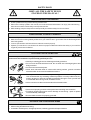
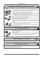
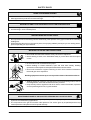
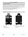
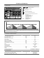
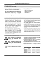
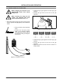
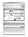
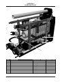
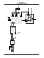
CONTENTS SAFETY RULES ............................................................................................................................................... 2 1. TECHNICAL INFORMATION .........................................................................................................................6 1.1 GENERAL EXPLANATIONS....................................................................................................................6 1.2 COMPONENTS OF MONOSTICK 160i...................................................................................................6 1.3 DATA PLATE ............................................................................................................................................7 1.4 TECHNICAL SPECIFICATIONS...............................................................................................................7 1.5 ACCESSORRIES.....................................................................................................................................7 2. INSTALLATION AND OPERATION................................................................................................................8 2.1 UPON RECEIPT AND CLAIMS................................................................................................................8 2.2 INSTALLING AND WORKING RECOMMENDATIONS ...........................................................................8 2.3 CONNECTIONS FOR MMA WELDING ...................................................................................................8 2.4 CONNECTIONS FOR TIG WELDING .....................................................................................................9 3. MAINTENANCE AND TROUBLESHOOTING..............................................................................................10 3.1 PERIODIC MAINTENANCE.............................................................................................................10 3.2 NONPERIODIC MAINTENANCE.....................................................................................................10 3.3 TROUBLESHOOTING .....................................................................................................................10 APPENDIX: APPENDIX 1: SPARE PARTS......................................................................................................................11 APPENDIX 2: ELECTRICAL DIAGRAM.......................................................................................................12 MONOSTICK 160i 1 SAFETY RULES OBEY ALL THE SAFETY RULES STATED IN THE MANUAL! IDENTIFYING SAFETY INFORMATION These symbols are being used to identify potential risks. When seen a safety symbol in the manual, it must be understood that there is an injury risk and following instructions must be read carefully to avoid potential risks. While welding, keep the third persons and especially the children away from the work area. UNDERSTANDING THE SAFETY WARNINGS Read carefully the manual and the labels and the safety warnings on the machine. Make sure that the warning labels positioned on your machine are in good order. Renew the damaged and the missing labels. Learn to operate the machine and how to make the controls properly. Operate your machine in convenient work areas. Improper modifications affect the safety of your machine negatively and shorten its lifetime. ELECTRICAL SHOCK CAN BE FATAL Installation procedure must comply with national electricity standards and other relevant regulations and ensure that installation is performed by qualified persons. Wear dry insulating gloves free of damage and body protection. Do not touch electrode with bare hand. Do not wear wet or damaged gloves and body protection. Do not touch live electrical parts. Never touch electrode while in contact with working surface, ground or another electrode which is connected to a different machine . Protect yourself from electric shock by insulating yourself from work and ground. Use non-flammable, dry insulating material if possible, or use dry rubber mats, dry wood or plywood, or other dry insulating material big enough to cover your full area of contact with the work or ground, and watch for fire. Never connect more than one electrode to the electrode holder. Turn off the machine, when not in use . Disconnect input plug or swtich off the power before working on the machine. Frequently inspect input power cord for damage or bare wiring - repair or replace cord immediately if damaged. Be sure that the machine is properly grounded. HOT PARTS CAN CAUSE SEVERE BURNS Do not touch hot parts. Allow cooling time before servicing. If needed to hold hot parts, use appropriate tool, insulating gloves and fireproof clothes. 2 MONOSTICK 160i SAFETY RULES BREATHING WELDING FUMES CAN BE HAZARDOUS TO YOUR HEALTH Inhaling fumes and gases over a long period of time, generated during welding is dangerous and forbidden . Irritation of the eyes, nose and throat are symptoms of inadequate ventilation. Take immediate steps to improve ventilation. Do not continue welding if symptoms persist. Install a natural or forced air ventilation system in the work area. Install an adequate ventilation system in the welding and cutting area, if needed install a system that can remove the fume and vapor accumulated in the entire work area, to prevent pollution use adequate filtration in discharge. In the event of welding in small, confined places, or welding lead, beryllium, cadmium, zinc, zinc coated or painted materials; also wear a fresh air supplied respirator in addition to the above mentioned rules . Always have a trained watchperson nearby, while working in small confined places. Avoid working in such confined places if possible. If gas cylinders are grouped in a different area, make sure that it is a well-ventilated area. When not being used, turn off the main cylinder valve and watch out for gas leakage . Shielding gasses such as argon is denser than air and when being used in confined places, it can be inhaled which is dangerous for health. Do not perform welding operations near chlorinated hydrocarbon vapors produced by degreasing or painting. ARC RAYS CAN BURN EYES AND SKIN Use adequate welding helmet with correct shade of filter (4 or 13 considering EN 379) to protect your eyes and face. Protect open parts of your body (arms, neck and ears) from arc rays by adequate protective clothing. To protect others by arc rays and hot metals, surround the working area with flame proof curtains which are higher than eye level and put up warning boards. SPARKS & FLYING METALS CAN INJURE EYES Welding, wire brushing and grinding cause sparks and flying metal. To prevent injuries wear appropriate safety glasses with side shields even under your welding helmet . MOVING PARTS CAN CAUSE INJURY Keep away from moving parts. Keep all doors, panels, and guards closed and secured. Wear shoes with metal protection over the fingers. MONOSTICK 160i 3 SAFETY RULES NOISE CAN DAMAGE HEARING Noise from certain industrial processes or equipments can damage hearing. Wear approved ear protection if noise level is high. WORKING IN SMALL AND CONFINED PLACES CAN BE DANGEROUS While welding and cutting in small, confined places, always have a trained watchperson nearby. Avoid working in such confined places. WELDING WIRE MAY CAUSE INJURY Do not point the torch toward any part of a human body, other persons or any type of metal when unwinding welding wire. While extracting the wire from the spool by hand, it may spring suddenly and injure you or a nearby person, protect especially your eyes and face. WELDING CAN CAUSE FIRE OR EXPLOSION Never weld near flammable material. It may cause fire or explosions. Before starting to weld, move flammables away or protect them with flame-proof covers. Do not weld on and cut closed tubes or pipes. Before welding on closed containers, open and clear them entirely. Welding operations on these parts must be performed with the utmost caution. Never weld containers or pipes containing or which have contained substances that could give rise to explosions. Welding equipments warms up so never position them on flammable surfaces. Welding sparks can cause fire. For that reason, keep extinguishing means, such as fire extinguishers, water and sand which are easy to reach. Keep security valves, regulators and other valves, used on flammable, explosive and compressed gas circuits, in good condition. MAINTENANCE MADE BY UNQUALIFIED PERSONS MAY CAUSE INJURIES Electrical devices should not be repaired by unqualified persons. Improper repairs can cause serious injuries or even death during applications. The components of the gas circuit works under pressure. The service given by unqualified persons may cause explosions and operators can be injured seriously. 4 MONOSTICK 160i SAFETY RULES FALLING UNIT CAN CAUSE INJURY Wrong positioned power source or other equipment may cause serious injury to persons or damage to objects. While repositioning the power source always carry by using the lifting eye. Never pull cable, hose or torch. Always carry the gas cylinders separately. Before carrying the welding and cutting equipment, disassemble all the connections between and separately carry the small ones by handgrips and the big ones by lifting eyes or by using appropriate vehicles like forklifts. Install your machine on flat platforms having maximum 10° slope that it does not fall over. Install it on well ventilated, non-confined places away from the dust, also avoiding the risk of falling caused by cables and hoses. For gas cylinders not to fall over, attach it to the mobile machine or to the wall with a chain. Ensure that operators easily reach the controls and connections on the machine. OVERUSE CAN CAUSE OVERHEATING Allow cooling period; follow rated duty cycle. Reduce current or reduce duty cycle before starting to weld again. Do not block airflow through the unit. Do not filter airflow to unit without the approval of manufacturer. ARC WELDING CAN CAUSE INTERFERENCE Electromagnetic energy arising during welding and cutting operations can interfere with sensitive electronic equipment such as microprocessors, computers, and computer-driven equipment such as robots. Be sure all equipment in the welding area is electromagnetically compatible. To reduce possible interference, keep weld cables as short as possible, close together, and down low, such as on the floor. To avoid possible EMC damages, locate welding operation as far as possible (100 meters) from any sensitive electronic equipment. Be sure this welding machine is installed and grounded according to this manual. If interference still occurs, the user must take extra measures such as moving the welding machine, using shielded cables, using line filters, or shielding the work area . PROTECTION Do not expose the welding machine to rain, protect from water drops and vapour. ENERGY EFFICIENCY Choose appropriate welding method and welding machine for your work. Choose appropriate welding current and welding voltage for the material and its thickness. If you will have a long break after welding, turn off the machine after cooler fan cooled the machine. MONOSTICK 160i 5 TECHNICAL INFORMATION 1. TECHNICAL INFORMATION 1.1 GENERAL EXPLANATIONS Monostick 160i is an inverter type portable, mono-phase DC MMA welding machine designed to weld stick electrodes up to 4 mm. This unit can also be used as a DC TIG* power source for touch-start applications. Even though the machine is mono-phase, due to the inverter technology it provides stable arc and good restriking performance, also the electric consumption is approximately 10% less than the silicon controlled rectifier equipments and 25% less than the magnetically controlled equipments. Monostick 160i proved well that it can work between 160 to 240 V 50/60 Hz line voltages. Therefore this machine is quite immune to mains voltage fluctuations and perfectly welds with generator-sets. Monostick 160i can also be used with long welding cables up to 25 mt. The machine is fan cooled and thermally protected against over heating. (*) For more information about TIG welding, check page 10. 1.2 COMPONENTS OF MONOSTICK 160i 8 3 2 4 5 6 1 7 Figure 1: Components of Monostick 160i 1 2 3 4 6 Power Switch Power LED Thermic / Error LED Current Adjustment Knob 5 6 7 8 Earth Cable and Welding Cable Socket (-) Earth Cable and Welding Cable Socket (+) Line Cable Inlet Handle MONOSTICK 160i TECHNICAL INFORMATION 1.3 DATA PLATE Single Phase Static Frequency Converter Transformer Rectifier Manual Metal Arc Welding Direct Current Descending Characteristics Line Input-1 Phase Alternating Current Appropriate To Operate In Dangerous Work Area X U0 U1 U2 I1 I2 IP23S S1 :Duty Cycle* :Open Circuit Voltage :Line Voltage and Frequency :Rated Welding Voltage :Input Current :Rated Welding Current :Protection Class :Input Power *Duty Cycle Temperature (°C) 1 6 min. 2 4 min. 6 min. 4 min. 6 min. 4 min. Time (min.) Duty cycle defines the percentage of welding time out of a period of 10 minutes at a given current and ambient temperature (standard is 40°C). For example, a welder with 60% duty cycle must be rested (2) for 4 minutes, after 6 minutes of continuous welding (1). 1.4 TECHNICAL SPECIFICATIONS TECHNICAL SPECIFICATIONS Line Voltage (Single Phase) Input Power (%25) Rated Input Current (%25) UNIT VALUE V 230 kVA 7,2 A 31,5 Power Factor 0,97 Open Circuit Voltage VDC 75 Welding Current Range ADC 10 - 160 Rated Welding Current (%25) ADC 150 A 32 - Delayed Fuse Protection Class IP23S Cooling Method Air Dimensions (LxWxH) Weight mm 160x312x405 kg 7,8 Standarts and Approvals CE, EN60974-1, EN60974-10 1.5 ACCESORRIES STANDARD ACCESORRIES PIECE PRODUCT CODE Electrode Holder and Cable (200A) 1 A390000200 Earth Clamp and Cable (16mm² - 3mt) 1 K301100203 MONOSTICK 160i 7 INSTALLATION AND OPERATION 2. INSTALLATION 2.1 UPON RECEIPT AND CLAIMS Be sure that you have received all the items that you have ordered. In case of any item is missing or damaged, contact your supplier immediately. In the event of damaged or missing delivery, draw up a record, take a photo of the damage and report it to the shipping agency and MAGMA MEKATRONIK with the photocopy of shipping bill. Standard pallet contains: ú Power Source ú Electrode Holder Cable ú Earth Clamp Cable ú User Manual E-mail: [email protected] Fax: +90 236 226 27 28 2.2 INSTALLATION AND WORKING RECOMMENDATIONS • DO NOT USE THE MACHINE WITH LONG ELECTRIC CABLES AT CONSTRUCTION SITES! Do not forget that electric cable carries 220V/50 Hz and these cables are not suitable to work in harsh environments, they can easily wear and tear which may lead to electric leakage to the metals where welders may be working on. ELECTRIK SHOCK CAN KILL or cause people to FALL DOWN from dangerously high places like scaffolding (iskele). Instead, ALWAYS use long WELDING CABLES for safety reasons. • For a better performance, keep the machine at least 20 cm away from the surrounding objects. Beware of excessive heat, dust and humidity around the machine. Try not to operate the machine under direct sunlight. Machines should be operated on lower capacities when ambient air temperature exceeds 40ºC. • Avoid welding at outdoors where it is windy and rainy, if this is a must, protect the welding area with curtains, mobile screens or tents. • Use suitable welding fume extraction systems. Use breathing apparatus if there is a risk of inhaling in confined places. • Respect the duty cycles given at the data plate. Exceeding the duty cycles frequently can damage the machine and this would void the warranty. • Do not use stronger fuses than those stated on the data plate. • Ensure that the earth clamp is tightly connected as close as possible to the welding location. Do not let welding current flow through any media other than welding cables; e.g. over the machine itself, gas tubes, chains, ball bearings, etc. 2.3 CONNECTIONS FOR MMA WELDING Before plugging your machine to the electrical line, check if the correct voltage exists. According to the polarity of the electrode to be used, insert welding cables into the appropriate socket (5-6) and tighten them by turning clock-wise. Connect the earth clamp tightly to the workpiece as close as possible to the welding area. While inserting the plug into the socket, pay attention that main switch is positioned to “OFF” “0”. Adjust the desired current and the machine is ready to weld. Below table is given as a reference for current adjustment of mild steel electrodes, please refer to the electrode manufacturer's recommendations. SWITCH ON the machine via power switch (1) and check if power LED (2) lights up and cooler fan works. 8 Diameter Rutile Basic Cellulosic 2.0 40-60 A -- -- 2.5 60-90 A 60-90 A 60-100 A 3.25 100-140 A 100-130 A 70-130 A 4.0 140-180 A 140-180 A 120-170 A MONOSTICK 160i INSTALLATION AND OPERATION 2.4 CONNECTIONS FOR TIG WELDING Before plugging your machine to the electrical line, check if the correct voltage exists. Install the Argon gas regulator onto the Argon gas cylinder. Connect the gas hose of the torch to the gas regulator. While inserting the plug into the socket, pay attention that main switch is positioned to “OFF” “0”. SWITCH ON the machine via power switch (1) and check if power LED (2) lights up and cooler fan works. TIG torch with a valve should be used. Figure 3: Connecting Gas Cylinder Connect the TIG torch power cable to the negative welding socket (5) and the earth cable to the positive welding socket (6) of the machine. Diameter of Electrode (mm) Diameter of Nozzle (mm) Welding Current (ADC) Gas Debit (lt/min) 1.0 6.3 15 - 70 6-8 1.6 9.5 30 - 150 6-8 Install the Argon gas regulator onto the Argon gas cylinder. Connect the gas hose of the torch to the gas regulator. Adjust the desired current and the machine is AR ready to weld. Figure 2: TIG Welding Connections MONOSTICK 160i 9 MAINTENANCE AND TROUBLESHOOTING 3. MAINTENANCE AND TROUBLESHOOTING Strictly follow the instructions contained in safety rules while servicing the machine. Before removing any screw on the machine for maintenance, power supply must be disconnected from the electric lines and enough time should be allowed for capacitor discharging. 3.1 PERIODIC MAINTENANCE ONCE IN EVERY 3 MONTHS Clean the labels on the machine, replace the worn out labels. Repair or replace the worn out welding cables. Clean and tighten the weld terminals. Check isolation of the electrode holder, earth clamp and their cables. ONCE IN EVERY 6 MONTHS Open the covers of the machine and clean with dry air. OR NOTE: The above recommended maintenence periods are indicative, these may vary according to the work shop conditions. 3.2 NONPERIODIC MAINTENANCE Contact tip and nozzle on the torch have to be cleaned regularly and changed if required. Contact tips must be in good condition, longer tips generally give better results. 3.3 TROUBLESHOOTING If the Thermal Protection LED (3) lights up while cooling fan is working and the machine doesn't weld; machine maybe overheated and stopped for auto protection due to overheat. Hot weather or working in high current values for long time may cause this. Let the machine on for a while in order to cool down itself with the cooling fan. After it cools enough, Thermal Protection LED (3) fades away and the machine can weld. When the Power LED (2) is lighting, cooling fan is working but the machine does not weld; turn off the machine for 1 minute then turn it on again and try to weld. If it still doesn't weld, contact to your authorized technical service. 10 MONOSTICK 160i APPENDIX 1 SPARE PARTS LIST 5 1 7 8 4 3 6 2 NO DESIGNATION IN ELECTRICAL DIAGRAM MATERIAL CODE 1 Upper Electronic Card E201B-03 K405000104 2 Middle Electronic Card E201B-02 K405000103 3 Underside Electronic Card E201B-01 K405000102 4 Current Adjustment Potentiometer Current 1K A410801001 5 Fan M1 A250200006 6 Filter Card E201B-FLT K405000101 7 Power LED - Green LED-Green Power A430801001 8 Thermic / Error LED - Red LED-Red TH-Err A430801002 Power Switch MONOSTICK 160i A310100008 11 Earth J4 N N 16A F S1 F E201B-FLT J3 J2 J1 Earth 2 M1 J2 24VDC J8 J7 E201B-01 J1 J5 6 2 P5 P8 E201B-02 Earth 1 2 3 4 1 2 P2 P3 1 P1 2 3 J1 T1 Power Transformer E201B-03 P4 2 1 12 +75°C TH1 - N.O. 1 2 Led-Green Power Current 1K - + Led-Redı TH-Err APPENDIX 2 ELECTRICAL DIAGRAM MONOSTICK 160i Organize Sanayi Bölgesi 5.Kısım 5503. Sokak No:1 MANİSA +90 236 226 27 00 +90 236 226 27 28 OWM 06.21.2011 Made in TÜRKİYE www.magmaweld.com