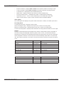
1
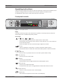
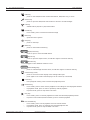
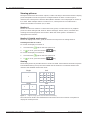
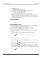
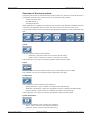
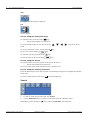
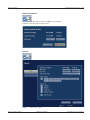
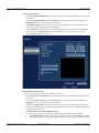
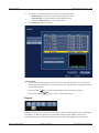
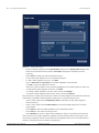
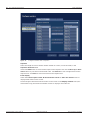
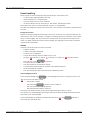
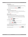
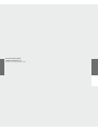
Divar 700 Series
Digital Hybrid Recorder / Digital Network Recorder
en
Operations manual
Divar 700 Series
Operating instructions | en
2
Operating instructions
These instructions explain the purpose of the front panel keys. The functions available can be
limited by setting passwords. Some functions may also require a software license.
An administrator has access to many more functions in the menu.
Front panel controls
Divar 700 Series
Figure 1
Front panel controls
Keys
The keys on the front panel control all functions. Symbols on the keys show the functions.
Inactive keys emit an audible beep when pressed.
Arrow keys:
Up
Down
Left
Right
–
move around through menu items or values when in menu mode
–
in PTZ mode, the arrow keys can be used to control the pan, tilt, or zoom functions
–
moves the visible area of the selected image in digital zoom mode
of the selected camera
Enter key
–
selects a submenu or menu item, or confirms selections made in menus
–
the selected cameo is shown full screen when viewing video in multiscreen mode
–
press to return to previous level or to exit menu system without saving
ESC key
Full screen key
–
press to go to full screen mode
Quad key
–
press to go to quad mode
–
in quad mode, press to toggle between the enabled quad screens
Multiscreen key
–
press to go to multiscreen mode
–
in multiscreen mode, press to toggle between enabled 3x3 and 4x4 screens
Digital zoom key
–
zooms in on the active full screen camera display
Sequence key
–
Bosch Security Systems
view cameras in sequence on full-screen or quad displays
Operations manual
F.01U.140.955 | v3.0 | 2009.11
3
en | Operating instructions
Divar 700 Series
OSD key
–
press to view date/time and camera information, date/time only, or none
Search key
–
press to open the date/time search menu to look for recorded images
PTZ key
–
enables either pan/tilt or pan/zoom modes
Freeze key
–
in live mode, press to freeze the selected image
Menu key
–
opens the menu system
Help key
–
press to view help
Mute key
–
press to mute audio monitoring
Open/Close key
–
press to open or close the DVD drawer
Export key
–
press to open the export menu; an indicator light is located on the key
–
toggles control between monitor A or B
–
press to acknowledge an alarm event; an indicator light is located on the key
Monitor key
Acknowledge key
Camera keys (1-16)
–
press to see a full-screen display of the analog video input
–
press again to see a full-screen display of an IP camera (if connected)
Pause key
–
in the playback mode, press to freeze the playback picture
Reverse key
–
in live mode, press to start reverse playback of recordings for the displayed cameras
–
in playback mode, press to start or speed up reverse playback
–
in pause mode, press to step back one frame
Play key
–
in live mode, press to resume playback from the last selected playback position
–
in pause or fast forward/reverse modes, press to resume playback
Fast forward key
F.01U.140.955 | v3.0 | 2009.11
–
in live mode, press to start playback from one minute earlier
–
in playback mode, press to speed up the forward playback rate
–
in pause mode, press to step forward one frame
Operations manual
Bosch Security Systems
Divar 700 Series
Operating instructions | en
4
Stop key
–
while in playback mode, press to return to live mode
Note:
IP camera numbering starts at 9 on an 8-channel hybrid model and at 17 on a 16-channel
hybrid model. So on a 16-channel hybrid unit with IP cameras, camera key 1 selects analog
camera 1 and, when pressed again, IP camera 17.
Indicators
The indicators on the front panel display light or flash to alert of various operating conditions.
Power - lights when the unit is powered
DVD- lights when a DVD is in the unit
USB - lights when a USB memory device is connected to the unit
Network - lights when a remote user is connected to the unit
Record - lights when the unit is recording video
Playback - lights when the unit is in playback mode
Monitor A - indicates monitor A is being controlled
Monitor B - indicates monitor B is being controlled
Temperature - flashes when internal temperature is outside operational range
Alarm - flashes when an alarm is detected
Motion - flashes when motion is detected in a video signal
Video loss - flashes when video loss is detected for a video input
System failure - flashes when a system failure is detected
Mouse Controls
All functions controlled by the front panel can, alternatively, be accessed using the supplied
USB mouse. All main DVR functions are accessible via the on-screen button panel. To display
the panel (monitor A only), move the mouse pointer to the bottom left of the screen. Press
ESC to remove it from the screen.
Figure 2
On-screen button panel
The buttons and indicators of the on-screen button panel work the same as the keys and
indicators on the front panel.
Bosch Security Systems
Operations manual
F.01U.140.955 | v3.0 | 2009.11
5
en | Operating instructions
Divar 700 Series
Viewing pictures
The hybrid version has two monitor outputs, A and B. The way in which these monitors display
pictures depends on how the system is configured. When an alarm or motion input is
detected, the camera picture with the Alarm/Motion indicator can be displayed on monitor A,
B, or both. When multiple alarms or motion occur, camera pictures are combined in a
multiscreen window on monitor A, B, or both.
Monitor A
Monitor A is the main monitor. It shows full-screen, quad, or multiscreen live or playback
pictures of both analog and IP cameras. Status messages, alarms, motion, and video loss
warnings are also displayed on this monitor. When the menu system is activated it is
displayed on this monitor.
Monitor B (hybrid version only)
Monitor B displays full-screen, quad, or multiscreen live pictures of analog cameras.
Selecting a monitor to control
To control the display on monitor A:
1.
Check that the
2.
If
light on the front panel is lit.
is not lit, press the monitor
key.
To control the display on monitor B:
1.
Check that the
2.
If
light on the front panel is lit.
is not lit, press the monitor
key
Viewing
The drawing shows all possible views for monitor A and B. Some multiscreen views may have
been disabled during set up. The Divar model and the number of connected cameras also
influence the available multiscreen views.
Single
4x4
1
1
2
3
4
5
6
7
8
9
10
11
12
13
14
15
16
Quad
1
3
Figure 3
3x3
2
4
1
2
3
4
5
6
7
8
9
Supports single, quad, 3x3, and 4x4 screen viewing
The multiscreen modes can have different multiscreens that can be shown in sequence to
display all camera pictures.
F.01U.140.955 | v3.0 | 2009.11
Operations manual
Bosch Security Systems
Divar 700 Series
Operating instructions | en
6
Multiscreen
To view different multiscreen displays on monitor A or B:
1.
2.
Press the multiscreen
key.
–
A multiscreen display of camera pictures appears on the active monitor.
–
The camera keys of the selected cameras light (green).
Press the multiscreen
–
key again to go to the next programmed multiscreen view.
Continue to press the multiscreen
key; the unit cycles through all enabled
multiscreen views.
Full-screen
To view a full-screen shot of a camera:
1.
2.
Press a camera key.
–
A full-screen shot of the selected analog camera appears.
–
The camera key of the selected analog camera lights (green).
–
Press the camera key again to display the linked IP camera.
–
The camera key of the selected IP camera lights (orange).
While in multiscreen mode, press enter
to view the active cameo in full-screen.
Note:
IP camera numbering starts at 9 on an 8-channel hybrid model and at 17 on a 16-channel
hybrid model. So on a 16-channel hybrid unit with IP cameras, camera key 1 selects analog
camera 1 and, when pressed again, IP camera 17.
Sequence
To view a sequence of live camera pictures of several cameras:
1.
Press the sequence
–
2.
Press the sequence
–
key.
A sequence of camera pictures appears, each for a pre-programmed dwell time.
key to stop sequencing.
Zooming, pressing the multiscreen key, or selecting a single camera also stops
sequencing.
Cameo assignment
Assigning cameras to cameos in a multiscreen view:
1.
2.
Use the arrow keys to select a cameo.
Press and hold a camera key to display and assign that camera’s picture in the active
cameo.
3.
Alternatively, right click a cameo with the mouse and choose a video input from the
context menu.
The cameo assignment that was made is used in playback mode as well as in live mode.
Freeze image
Freezing a camera shot on monitor A:
1.
2.
Press the freeze
key to freeze the picture in the active cameo.
Press the freeze
key again to return to live viewing.
Alternatively, right click and select Freeze or Unfreeze from the context menu using the
mouse.
When viewing a camera picture in full-screen mode, then this picture is frozen. The zoom
function can be used on a frozen picture. When changing viewing mode, any frozen pictures
are released.
Bosch Security Systems
Operations manual
F.01U.140.955 | v3.0 | 2009.11
7
en | Operating instructions
Divar 700 Series
Zoom
To zoom in on a video image:
1.
Press the zoom
–
key.
The picture is enlarged by a factor of 2.
2.
Use the arrow keys to select the area of the picture to be displayed.
3.
Press the zoom
–
key again to zoom in further.
The picture is enlarged by a factor of 4.
4.
Use the arrow keys to select the area of the picture to be displayed.
5.
Press the zoom
key again to return to a full picture and leave the zoom mode.
Alternatively, right click and select Zoom or Exit zoom to enable or disable zoom mode
with the mouse. While in zoom mode, click on an area of the screen to zoom in on. Use
the scroll wheel to zoom in and out.
Live and playback
Live mode
The live mode is the normal operating mode of the unit where live pictures are viewed from
the cameras. From live mode, switching to playback mode or to the system menu is possible.
Accessing playback functions
Access to playback functions may require a password. Discuss this with the administrator.
1.
To search, use the top menu and click the search icon.
2.
Choose Event search or Date/time search from the pull-down menu.
Alternatively, press the search
key to switch to date/time search directly.
To enter the playback mode, use one of the following keys:
–
Press the rewind
key to start reverse playback of recordings for the displayed
cameras.
–
Press the fast forward
–
Press the play
Press the stop
key to start playback from one minute earlier.
key to resume playback from the last selected playback position.
key to switch back to live viewing. An alarm also switches the unit back to
live viewing.
Playback mode
In playback mode, the video control keys operate as follows:
–
Press the rewind
key to start reverse playback of recordings. Pressing it again and
again increases the display rate to a maximum before returning it back to normal speed
again. Press the rewind
–
–
Press the pause
key in the pause mode to step back one frame at a time.
key to freeze the picture.
Press the fast forward
key to start playback of recordings. Pressing it again and
again increases the display rate to a maximum before returning it back to normal speed
again. Press the forward
–
Press the play
Press the stop
key in the pause mode to step forward one frame at a time.
key to resume playback.
key to switch back to live viewing. An alarm also switches the unit back to
live viewing.
F.01U.140.955 | v3.0 | 2009.11
Operations manual
Bosch Security Systems
Divar 700 Series
Operating instructions | en
8
Overview of the menu system
The menu gives access to several functions to help use the unit. Access to some menu items is
password protected. There are three ways of accessing the menu system:
–
via the front panel keys,
–
the USB mouse, or
–
a Intuikey keyboard.
Slight differences in navigation and selection are only due to the differences between the keys
on the unit, the keyboard and the mouse. The menu structure is the same in all cases.
The top menu consists of four main menus with drop-down submenus, a help item and an exit
item.
Figure 4
Top menu
Search
The Search menu contains two submenus:
–
Date/time - plays back video from a specific date and time.
–
Events search - searches for events in a specific time frame.
These submenus can only be accessed if playback rights have been given.
Export
The Export menu is used to archive a video clip to a USB memory device or DVD.
This submenu can only be accessed if export rights have been given.
Configuration
The Configuration menu contains three submenus:
–
Quick installation - opens a wizard to configure basic DVR settings.
–
Advanced configuration - opens the configuration menu to configure all DVR settings.
–
Monitor settings - opens a menu to configure the monitor output settings.
These submenus can only be accessed if configuration rights have been given.
System information
The System information menu contains two submenus:
Bosch Security Systems
–
Status - opens a menu to view status information.
–
Log Book - opens a menu to view the system log.
Operations manual
F.01U.140.955 | v3.0 | 2009.11
9
en | Operating instructions
Divar 700 Series
Help
The Help function displays a help text.
Exit
Click to log off.
Access using the front panel keys
To open the menu, press the menu
–
key.
The top menu appears on monitor A.
To move through a menu or list, use the arrow
keys on the front
panel.
To select a submenu or item, use the enter
To go back, use the escape
key.
key
To open the help text, press the help
key.
To exit the menu, press the escape
key.
Access using the mouse
To open the menu, move the pointer to the top of the screen.
–
The top menu appears on monitor A.
To select a menu item, move the pointer over it and left click.
Access using the Intuikey keyboard
Press the Menu key to access the top menu. Use the keyboard joystick to navigate through the
menu items.
To select a menu item use the enter
key on the keyboard.
Search
Figure 5
Top menu - Search
1.
To search, enter the top menu and click Search.
2.
Choose Date/time search or event or text search from the pull-down menu.
Alternatively, press the search
F.01U.140.955 | v3.0 | 2009.11
key to switch to Date/time search directly.
Operations manual
Bosch Security Systems
Divar 700 Series
Operating instructions | en
10
Date/time search
Enter the start date and time and click OK to start playback.
Playback of the displayed cameos starts.
Figure 6
Search by date and time
Search
Figure 7
Bosch Security Systems
Search menu - Events
Operations manual
F.01U.140.955 | v3.0 | 2009.11
11
en | Operating instructions
Divar 700 Series
Events search criteria
–
Under Start time and End time, fill in date and time values to determine the time span of
–
To set the Search direction, select Forward to search from start time to end time or
the search.
Backward to search from end time to start time.
–
Under Video inputs, check the inputs to search for (highlight the un-numbered box to
select all). The selected inputs are highlighted.
–
Under Search for check the boxes to search for contact, motion, video loss and system
events. Check the Alarms only box so that the search is restricted to alarm events.
–
Select Search to start the search.
Figure 8
Search menu - Smart motion
Smart motion search criteria
1.
Set the smart motion search parameters as follows:
–
Under Start time and End time, fill in date and time values to determine the time span of
–
To set the Search direction, select Forward to search from start time to end time or
the search.
Backward to search from end time to start time.
–
Adjust the Trigger level slider to set the level of motion that will be detected. Sliding to
the right raises sensitivity, sliding to the left lowers sensitivity. The highest value detects
even the slightest motion.
–
Select the input to search using Video input.
2.
To define the motion sensitive area in the smart motion preview cameo window:
F.01U.140.955 | v3.0 | 2009.11
–
Select Draw cells and draw in the motion cameo to add or increase detection areas.
–
Select Erase cells and draw in the motion cameo to erase or reduce detection areas.
Operations manual
Bosch Security Systems
Divar 700 Series
Operating instructions | en
3.
To activate or clear the entire area, select one of the following:
–
4.
12
Draw all cells to activate the entire motion detection area.
–
Erase all cells to clear the entire motion detection area.
–
Check the Show grid box to outline grid zones.
Select Search to start the search.
Figure 9
Search menu - Search results
Search results
–
The recording fitting the filter and closest to the selected date and time is shown first.
–
Use the up/down arrow keys to move through the list. The selected recording is shown in
the preview window.
–
Press the enter
key for a full-screen playback of the selected recording.
–
Press the escape
key to return to the search menu.
Export
Figure 10
Top menu - Export video
The export menu is accessed from the top menu. It allows writing segments of recorded video
and audio to a USB storage device or recordable DVD. The main export screen shows
information about the connected media and a list of the video segments to be archived.
Bosch Security Systems
Operations manual
F.01U.140.955 | v3.0 | 2009.11
13
en | Operating instructions
Figure 11
–
Divar 700 Series
Export video menu
Choose a memory device from the Destination selection box. Media status displays the
status of the selected memory device; Free space displays the available space for
archiving.
Select Erase to empty the selected memory device.
–
A list of the video segments to be archived is displayed.
–
To add a video segment to the list, click Add.
Fill in a Start time and End time for the video segments to be archived.
Click OK to place the segment in the list.
Select the camera numbers to be archived (highlight the un-numbered box to select all).
–
To add another video segment to the list, click Add.
–
To change a video segment in the list, select it and click Change.
–
To remove a video segment from the list, select it and click Remove.
The archive list is saved until archiving is carried out. Video segments that have been partially
overwritten or deleted fromthe internal hard drive(s) are removed from the list.
–
Place a check mark next to Authenticity check to authenticate the video segments
–
Place a check mark next to Finalize media to ensure that DVD media can be read on
before archiving.
other players.
–
Select Start to write the video segments to the destination device.
–
Select Stop to cancel the archiving process.
–
Select Details for an error report if the authenticity check or archiving is unsuccessful.
If the total size of the video segments is greater than the memory device’s free space, then
only the first segments that fit are archived. Those segments that are not archived remain in
the list so that they can be archived to a new device.
F.01U.140.955 | v3.0 | 2009.11
Operations manual
Bosch Security Systems
Divar 700 Series
Operating instructions | en
14
Configuration
Figure 12
Top menu - Configuration
The Configuration menu is accessed from the top menu. The Configuration menu contains
three submenus:
–
Quick Installation - opens a wizard to configure basic settings. For more information refer
to Section 3 Quick install.
–
Advanced configuration - opens the advanced configuration menu to configure all
–
Monitor Settings - opens a menu to configure monitor settings.
settings.
Monitor settings
The Monitor settings submenu contains display settings for monitor A (and monitor B for
hybrid models).
Display options
Select a transparent background to see the camera display behind the menus.
Select the color for the cameo borders (black, white or gray).
Multiscreens
Select the multiscreens to be viewed.
Bosch Security Systems
Operations manual
F.01U.140.955 | v3.0 | 2009.11
15
en | Operating instructions
Figure 13
Divar 700 Series
Configure monitors menu - Sequence
Sequence
Select the length of time a camera remains visible on screen (1 to 60 seconds) in the
Sequence dwell time field.
Use the the Add button to move camera inputs to the sequence list. Use the Move up or Move
down buttons to put them in the desired order. Use Remove to clear a single item from the
sequence list. Use Erase to clear all items from the sequence list.
Event display
Check the Contact inputs events, Motion detection events or Video loss alarms boxes to
display these events on the screen.
Set the length of time these events remain on the screen in the Display duration field (nonalarm events only) and enter the number of lines to display in the event list.
F.01U.140.955 | v3.0 | 2009.11
Operations manual
Bosch Security Systems
Divar 700 Series
Operating instructions | en
16
System information
Figure 14
Top menu - System information
The System information menu is accessed from the top menu. The System information menu
contains two submenus:
–
Status - opens a menu to view status information.
–
Logbook - opens a menu to view the system log.
Status
The Status submenu contains five tabs displaying status information.
Version Info
The version information tab displays the installed firmware version, serial number, and other
version-related information for service purposes.
Storage status
The storage status tab displays information on disk size and content.
Figure 15
Bosch Security Systems
Status menu - Storage status
Operations manual
F.01U.140.955 | v3.0 | 2009.11
17
en | Operating instructions
Divar 700 Series
–
Earliest recording - displays date and time of the earliest (oldest) recording on disk.
–
Latest recording - displays date and time of the latest (newest) recording on disk.
–
Total Disk Size - displays the total installed disk space.
–
RAID status - displays enabled if the disks are used as a RAID array.
–
Time till overwrite appr. - estimated time video is retained until overwriting.
–
Authenticity check... - click to check authenticity of recorded audio and video.
–
Disks in active disk set - gives a status overview of the installed harddisks.
Video signals
The video signals tab displays the system video mode (PAL or NTSC) and video input status.
Recording status
Currently active profile - displays current profile
Alarm recording at input - displays which inputs are in alarm recording mode
Motion recording at input - displays which inputs are in motion recording mode
Current recording status - displays video and audio recording mode and status for each input
Sensors
Displays actual temperature and voltage sensor values. If temperature levels are outside of
the normal range, the displayed values are yellow. If this occurs, check that the ambient
temperature is within the recommended specifications and that there is proper air ventilation.
If the temperature reaches a critical level, the unit automatically shuts down. To restart the
unit, disconnect the power cord, wait for at least 30 seconds, and then reconnect the power
cord.
Sensor name
Lower limit
Upper limit
Processor
5 °C / 41 °F
100 °C / 212 °F
Air inlet
5 °C / 41 °F
45 °C / 113 °F
Air outlet
5 °C / 41 °F
55 °C / 131 °F
Hard disk #1
5 °C / 41 °F
55 °C / 131 °F
Hard disk #2
5 °C / 41 °F
55 °C / 131 °F
Hard disk #3
5 °C / 41 °F
55 °C / 131 °F
Hard disk #4
5 °C / 41 °F
55 °C / 131 °F
Voltage level
Lower limit
Upper limit
12 Volt
10.8 V
13.2 V
5 Volt
4.7 V
5.3 V
3.3 Volt
3.1 V
3.5 V
Table 5.1
Table 5.2
F.01U.140.955 | v3.0 | 2009.11
Temperature sensors
Power supply levels
Operations manual
Bosch Security Systems
Divar 700 Series
Operating instructions | en
18
Logbook
The logbook menu is used to display a filtered history of system events.
Logbook filter
Set various filter criteria to search in a specified time period for various system events.
Figure 16
Logbook menu - Logbook filter
–
Enter start and end times.
–
Make a selection of which system events to show.
–
Logbook contents - shows the earliest and latest available log contents.
–
Show - click to show the results.
Logbook results
Shows the Date, Time, and Event type of various system events. A video preview screen of the
selected event is shown, if applicable.
Bosch Security Systems
Operations manual
F.01U.140.955 | v3.0 | 2009.11
19
en | Operating instructions
Divar 700 Series
Event handling
Various types of events change the way the unit works. These events are:
–
a contact input signal applied to the unit;
–
motion detection in a camera signal;
–
a loss of video from one of the cameras;
–
an internal alert from the unit itself (i.e. disk failure, temperature alarm).
The way the unit reacts to events depends on how it is programmed.
An event can change the way the unit works and, if it is an alarm, can require a response from
the user.
Background events
Events can change background tasks that a user may not notice. Unit responses that are not
visible to the user are, for example, a change in recording speed, the activation of the output
relay, or event logging. The unit can also be configured to record upon the activation of an
event or it might change the way the camera images are displayed on the monitors without
requiring user intervention.
Alarms
An alarm can cause the unit to react as follows:
–
A beeper sounds.
–
A status message is displayed.
–
An alarm icon is displayed.
–
The border around a cameo changes color to red.
–
An alarm
–
The indicator on the
indicator, a motion
indicator or a video loss
indicator flashes.
key flashes.
–
An output relay is activated.
–
The view modes on the monitors change.
–
A controllable camera might be moved to a pre-defined position.
–
Recording behavior changes.
–
The unit changes the way it operates via pre-defined profiles.
Acknowledging an alarm
Press the acknowledge key
to acknowledge the alarm or use the mouse to click
on the on-screen button panel.
–
The beeper is silent.
–
The alarm and
–
The alarm status message disappears.
–
The last-used view mode is restored.
indicators are no longer lit.
The alarm icon remains visible as long as the input causing the alarm is active.
If an alarm is not acknowledged, the beeper switches off after the dwell time but the alarm
still needs to be acknowledged.
If auto-acknowledge is enabled, the beeper and the alarm
and
indicators,
switch off after the dwell time.
F.01U.140.955 | v3.0 | 2009.11
Operations manual
Bosch Security Systems
Divar 700 Series
Operating instructions | en
20
Contact inputs
If a contact input causes an alarm
–
Monitors A and B (hybrid version only) can display an array of pre-selected cameras.
–
Monitor A: The border around the displayed cameos is red. The alarm icon is displayed in
the corresponding cameo. An alarm status message is displayed.
–
The alarm beeper sounds. The alarm
and the
indicators flash.
–
Controllable cameras might be moved to pre-defined positions.
Motion events
If a motion detection signal causes an event
–
Monitors A and B (hybrid version only) can switch to display the motion events.
–
The motion icon is displayed in the corresponding cameo. An alarm status message is
displayed.
–
The motion
indicator on the front panel flashes.
Video loss alarm
If the loss of a video signal causes an alarm:
Monitor A or B (hybrid version only) can be configured to show the video loss signal.
–
One or both monitors can switch to a multiscreen view. The lost camera signal is
displayed as a black cameo with the video loss message. On monitor A, the border
around the camera with the video loss is red. An alarm status message is displayed.
–
The alarm beeper sounds.
–
The video loss
and
indicators flash.
Acknowledging a video loss alarm
Press the acknowledge key
to acknowlede a video loss alarm.
–
The beeper is silent.
–
The video loss
–
The alarm status message disappears.
–
The last-used view mode is restored.
and
indicators are no longer lit.
If the camera with video loss is visible, the black cameo and the video loss message continue
to be displayed as long as there is no video present.
If an alarm is not acknowledged, the beeper switches off after the dwell time but the alarm
still needs to be acknowledged.
If auto-acknowledge is enabled the beeper, and the video loss
and
indicators,
switch off after the dwell time.
Bosch Security Systems
Operations manual
F.01U.140.955 | v3.0 | 2009.11
Bosch Security Systems
www.BoschSecurity.com
© Bosch Security Systems, 2009