1
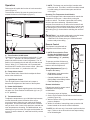
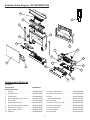
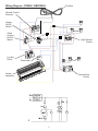
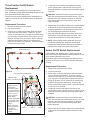
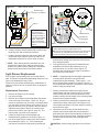
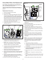
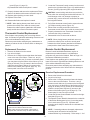
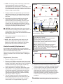
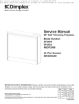
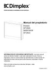
Service Manual
26” Self Trimming Fireplace with Integrated On/Off Remote
Model Numbers:
DF2608 - MOD / to A
DF2622 - MOD /
NBDF2608 - MOD / to D
Dimplex North America Limited
1367 Industrial Road Cambridge ON Canada N1R 7G8
1-888-346-7539 www.dimplex.com
REV
PCN
DATE
00
11527
Jul 20, 09
01
11658
Oct 13, 09
02
11879
Feb 12, 10
03
Oct 3,11
In keeping with our policy of continuous product development, we reserve the right to make changes without notice.
7400200000R03
Table of Contents
Operation. . . . . . . . . . . . . . . . . . . . . . . . . . . . . . . . . . . . . . . . . . . . . . . . . . . . . . . . . . . . . . . . . . . . . 3
Exploded Parts Diagram - DF2608/NBDF2608. . . . . . . . . . . . . . . . . . . . . . . . . . . . . . . . . . . . . . . . 4
Wiring Diagram - DF2608 / NBDF2608. . . . . . . . . . . . . . . . . . . . . . . . . . . . . . . . . . . . . . . . . . . . . . 5
Exploded Parts Diagram - DF2622. . . . . . . . . . . . . . . . . . . . . . . . . . . . . . . . . . . . . . . . . . . . . . . . . 6
Wiring Diagram - DF2622. . . . . . . . . . . . . . . . . . . . . . . . . . . . . . . . . . . . . . . . . . . . . . . . . . . . . . . . 7
Front Glass Replacement. . . . . . . . . . . . . . . . . . . . . . . . . . . . . . . . . . . . . . . . . . . . . . . . . . . . . . . . 8
Light Bulb Replacement . . . . . . . . . . . . . . . . . . . . . . . . . . . . . . . . . . . . . . . . . . . . . . . . . . . . . . . . . 8
Mirror Replacement. . . . . . . . . . . . . . . . . . . . . . . . . . . . . . . . . . . . . . . . . . . . . . . . . . . . . . . . . . . . . 9
Three Position On/Off Switch Replacement . . . . . . . . . . . . . . . . . . . . . . . . . . . . . . . . . . . . . . . . . 10
Heater On/Off Switch Replacement . . . . . . . . . . . . . . . . . . . . . . . . . . . . . . . . . . . . . . . . . . . . . . . 10
Light Dimmer Replacement. . . . . . . . . . . . . . . . . . . . . . . . . . . . . . . . . . . . . . . . . . . . . . . . . . . . . . . 11
Flame Action Control Replacement. . . . . . . . . . . . . . . . . . . . . . . . . . . . . . . . . . . . . . . . . . . . . . . . 12
Flicker Motor/Flicker Rod Replacement . . . . . . . . . . . . . . . . . . . . . . . . . . . . . . . . . . . . . . . . . . . . 13
Thermostat Control Replacement. . . . . . . . . . . . . . . . . . . . . . . . . . . . . . . . . . . . . . . . . . . . . . . . . 14
Remote Control Replacement. . . . . . . . . . . . . . . . . . . . . . . . . . . . . . . . . . . . . . . . . . . . . . . . . . . . 14
Log Driver Control Board Replacement (DF2608 only). . . . . . . . . . . . . . . . . . . . . . . . . . . . . . . . . 15
Heater Assembly Replacement. . . . . . . . . . . . . . . . . . . . . . . . . . . . . . . . . . . . . . . . . . . . . . . . . . . 16
Power Cord Replacement. . . . . . . . . . . . . . . . . . . . . . . . . . . . . . . . . . . . . . . . . . . . . . . . . . . . . . . 17
2
Operation
! NOTE: The heater may emit a slight, harmless odor
when first used. This odor is a normal condition caused
by initial heating of internal heater parts and will not
occur again.
This section will explain the function of each convenient
control (Figure 2).
To access the controls, flip open the control panel cover
towards the bottom of the fireplace (Figure 1).
Resetting The Temperature Cutoff Switch
This unit is equipped with a thermostat which controls the
temperature of the room. It does this by turning the
heater on and off. The heater is protected with a safety
device to prevent overheating. Should the heater
overheat, an automatic cut out will turn the heater off and
it will not come back on without being reset. It can be reset
by switching the Three Position On/Off Switch to Off (“ o ”)
and waiting five (5) minutes before switching the unit back
on.
Figure 1
CAUTION: If you need to continuously reset the heater,
unplug the unit and call Technical Support at
1-888-346-7539. Please have your model and serial
number ready when calling.
Figure 2
A
B
C
E
D
Remote Control
The fireplace is supplied with an
integrated on/off remote control.
! Note: Ensure that the Three
Position On/Off Switch on the
fireplace is set to the remote
control setting (“ II ” position).
A. Three Position On/Off Switch
The switch has two (2) on positions marked with “ I ” and
“ II ”. The “ I ” position is for manual operation. In this
position the built-in remote control is bypassed. The “ II ”
position is for operating the unit with the provided remote
control. When in “ II ” position the unit is operated with
the ON and OFF buttons of the remote control. When the
switch is in the center “ o ” position the unit is off..
To operate, push the ON button to
turn the fireplace on, push the OFF
button to turn the fireplace off.
Battery Replacement (Figure 3)
To replace the battery:
• Slide battery cover open on the
hand held transmitter.
• Correctly install one (1) 12 Volt
(A23) battery in the battery holder.
• Close the battery cover.
B. Flame Action Control
Turn the Flame Action Control knob to adjust the flame
action to the desired level.
C. Light Dimmer Control
Turn the Light Dimmer Control knob to increase or
decrease the brightness of the interior of the fireplace.
Figure 3
OFF
Button
ON
Button
Battery
Cover
Remote Initialization
Follow these steps for remote control
initialization and if required,
reinitialization:
1. Disconnect power to fireplace.
2. Set the Three Position On/Off Switch to the Remote
position (Figure 2A).
3. Wait a minimum of five (5) seconds and then reacquire
power to fireplace.
4. Within 10 seconds of reacquiring power, press the ON
button located on the remote control transmitter.
D. Heater On/Off Switch
The Heater On/Off Switch supplies power to the heating
unit when the Three Position On/Off Switch (A) is on (“ I ”
or “ II ” positions).
E. Thermostat Control
To adjust the temperature to your individual requirements,
turn the thermostat control clockwise all the way to
turn on the heater. When the room reaches the desired
temperature, turn the thermostat knob counter clockwise
until you hear a click. Leave in this position to maintain the
room temperature at its setting. For additional heat, turn
clockwise until you hear the click again and the heater will
turn on. To turn the heater off, rotate the knob fully counter
clockwise.
! NOTE: You will have only 10 seconds to perform this last
step. Failure to do so will result in these steps needing
to be followed again.
3
Exploded Parts Diagram - DF2608/NBDF2608
4
16
12
10
13
7
18
1
11
8
9
14
3
19
17
15
1
2
6
Replacement Parts List
5
DF2608
Part Number
Replacement Part:
1. Log Set. . . . . . . . . . . . . . . . . . . . . . . .
2. Log Set Driver . . . . . . . . . . . . . . . . . .
3. Flicker Motor . . . . . . . . . . . . . . . . . . .
4. Heater Assembly (with cutout) . . . . . .
5. Thermostat . . . . . . . . . . . . . . . . . . . .
6. Heater On/Off Switch . . . . . . . . . . . .
7. Three Position Selection Switch . . . .
8. Flame Action Control . . . . . . . . . . . . .
9. Light Dimmer Control . . . . . . . . . . . .
10. Cord Set . . . . . . . . . . . . . . . . . . . . . .
6904400359
0439560100RP
3000390100RP
3000240200KIT
2000330100RP
2300150100RP*
2800210500RP
2800210100RP
3000240500RP
3000250100RP
4100040200RP
11. Single Lamp Holder . . . . . . . . . . . . . .
12. Double Lamp Holder . . . . . . . . . . . . .
13. Mirror . . . . . . . . . . . . . . . . . . . . . . . . .
Mirror (NBDF2608). . . . . . . . . . . . . . .
14. Front Glass . . . . . . . . . . . . . . . . . . . .
15. Control Knob (3 on unit). . . . . . . . . . .
16. Remote Transmitter . . . . . . . . . . . . . .
17. Remote Receiver . . . . . . . . . . . . . . .
18. Terminal Block . . . . . . . . . . . . . . . . . .
19. Flicker Rod . . . . . . . . . . . . . . . . . . . .
4
2500150300RP
2500400300RP
5901210200RP
5901450100RP
5901220100RP
8800000200RP
3000370500RP
3000380200RP
4000070100RP
5901250100RP
Wiring Diagram - DF2608 / NBDF2608
Cord Set
Remote Control
Receiver
Heater
On/Off
Switch
Three
Position
On/Off
Switch
Log Set
Driver
Light Dimmer
Control
Thermostat
Heater
Assembly
Flame Action
Control
5
Exploded Parts Diagram - DF2622
3
20
11
9
22
15
12
6
21
17
10
7
8
13
2
18
19
Replacement Parts List
5
DF2622
Part Number
Replacement Part:
1. Log Set. . . . . . . . . . . . . . . . . . . . . . . .
2. Flicker Motor . . . . . . . . . . . . . . . . . . .
3. Heater Assembly (with cutout) . . . . . .
4. Thermostat . . . . . . . . . . . . . . . . . . . .
5. Heat On/Off Switch . . . . . . . . . . . . . .
6. Three Position On/Off Switch . . . . . .
7. Flame Action Control . . . . . . . . . . . . .
8. Light Dimmer Control . . . . . . . . . . . .
9. Cord Set . . . . . . . . . . . . . . . . . . . . . .
10. Single Lamp Holder . . . . . . . . . . . . . .
11. Double Lamp Holder . . . . . . . . . . . . .
12. Mirror . . . . . . . . . . . . . . . . . . . . . . . . .
16
14
1
4
6904400659
13. Front Glass . . . . . . . . . . . . . . . . . . . .
14. Control Knob (3 on unit). . . . . . . . . . .
15. Remote Transmitter . . . . . . . . . . . . . .
16. Remote Receiver . . . . . . . . . . . . . . .
17. Terminal Block . . . . . . . . . . . . . . . . . .
18. Flicker Rod . . . . . . . . . . . . . . . . . . . .
0439560200RP
3000240200KIT
2000330100RP
2300150100RP*
2800210100RP
2800210500RP
3000240500RP
3000250100RP
4100040200RP
2500150300RP
2500400300RP
5901450100RP
5901220100RP
8800000200RP
3000370500RP
3000380200RP
4000070100RP
5901250100RP
Stainless Steel Replacement Parts for DF2622SS
19. Stainless Steel Control Cover . . . . . . 1018760180RP
20. Stainless Steel Top Trim. . . . . . . . . . . 1018830180RP
21. Stainless Steel Right Side Trim. . . . . . 1018840180RP
22. Stainless Steel Left Side Trim . . . . . . 1018830280RP
6
Wiring Diagram - DF2622
Cord Set
Remote Control
Receiver
Heater
On/Off
Switch
Three
Position
On/Off
Switch
Light Dimmer
Control
Log Set
Driver
Heater
Assembly
Thermostat
Flame Action
Control
7
Front Glass Replacement
Upper Bulb Requirements:
A quantity of two (2) chandelier or candelabra bulbs with an
E-12 (small) socket base, 15 Watt rating are required.
Do not exceed 15 Watts per bulb
If unit was operating prior to servicing allow at least 10
minutes for light bulbs and heating element to cool off to
avoid accidental burning of skin.
Disconnect power before attempting any maintenance or
cleaning to reduce the risk of electric shock or damage to
persons.
Upper Bulb Replacement Procedure
1. 2. 3. 4. 5. Replacement Procedure
1. 2. 3. 4. 5. 6.
Slide firebox out of mantel.
Lay unit on it’s back for safe removal of Front Glass.
Remove three (3) Phillips screws from right side of Trim.
Remove Trim.
Slide glass to the right side of the firebox to remove
(Figure 4).
Reassemble using replacement Front Glass in reverse
order as described above.
Slide firebox out of mantel.
Lay unit on it’s back for safe removal of Front Glass.
Remove three (3) Phillips screws from right side of Trim.
Remove Trim.
Slide glass to the right side of the firebox to remove
(Figure 4).
CAUTION: Even though the glass is safety glass it may
break if bumped, struck of dropped. Care must be
taken when handling the glass.
6. Upper bulbs are located in the upper left and upper
right corners of firebox, behind the Light Block Bracket
(Figure 5).
CAUTION: Even though the glass is safety glass it may
break if bumped, struck or dropped. Care must be
taken when handling the glass.
Figure 5
Figure 4
Light Block screws (4)
Light Block
Flicker Rod
shaft
Light Filter
Bracket
screws (2)
Trim
Log Set
Assembly
Lower Light
Bulbs (3)
Front Glass
7. Remove the four (4) Phillips screws that attach the Light
Block to the firebox (Figure 5).
8. Unscrew bulbs counter clockwise to remove.
9. Insert new bulbs and screw in clockwise.
10.Reattach Light Block Bracket.
11.Lay unit on it’s back, slide Front Glass back into position
and attach Trim.
Light Bulb Replacement
Allow at least five (5) minutes for the light bulbs to cool
before touching them to avoid accidental burning of the
skin. The light bulbs need to be replaced when you notice
a dark section of the flame or when the clarity and detail
of the log ember bed exterior reduces. There are three
(3) bulbs under the Log Set Assembly, which generate the
flames and embers, and two (2) bulbs above that illuminate
the log exterior.
It is a good idea to replace all of the light bulbs at one time
if they are close to the end of their rated life. Group
replacement will reduce the number of times you need to
open the unit to replace the light bulbs.
Lower Bulb Requirements:
A quantity of three (3) chandelier or candelabra bulbs with
an E-12 socket base, 60 Watt rating are required.
Do not exceed 60 Watts per bulb
Lower Bulb Replacement Procedure
1. Slide firebox out of mantel.
2. Lay unit on it’s back for safe removal of Front Glass.
3. Remove three (3) Phillips screws from right side of Trim.
8
Mirror Replacement
4. Remove Trim.
5. Slide glass to right side of firebox to remove (Figure 4).
If the fireplace was operating prior to servicing allow at
least 10 minutes for light bulbs and heating element to cool
off to avoid accidental burning of skin.
Disconnect power before attempting any maintenance or
cleaning to reduce the risk of electric shock or damage to
persons.
CAUTION: Even though the glass is safety glass it may
break if bumped, struck of dropped. Care must be
taken when handling the glass.
6. Pull the front edge
of the plastic Ember
Bed or plastic grate
up and forward until
the rear tab releases
from the ledge
located at the bottom
of the Mirror
(Figure 6).
Figure 6
Log
Ember Bed
Replacement Procedure
1. Slide firebox out of mantel.
2. Lay unit on it’s back for safe removal of Front Glass.
3. Remove three (3) Phillips screws from the right side of Trim.
4. Remove Trim.
5. Slide glass to right side of fireplace to remove
(Figure 4, Page 8).
Back
Ledge
Rear
Tab
Side Section
! IMPORTANT: Only
handle the Log Set
Assembly by the Ember Bed or plastic grate.
Front
Edge
! NOTE: Log Set Assembly fits tightly into firebox, some
force may be necessary to remove.
CAUTION: Even though the glass is safety glass it may
break if bumped, struck of dropped. Care must be
taken when handling the glass.
6. Pull the front edge of the plastic Ember Bed or plastic
grate up and forward until the rear tab releases from
the ledge located at the bottom of the Mirror.
7. Disconnect LED harness (DF2608 only).
8. Set Log Set Assembly in front of firebox.
9. Remove Flicker Rod by pulling rod to the right, towards
the Flicker Motor. Bend the Flicker Rod enough to
clear the bracket on the left, lift out and pull Flicker Rod
off of Flicker Motor shaft (Figure 5, page 8).
10.Remove four (4) Phillips screws (two (2) per side)
which attach Light Filter Bracket for easier access to
light bulbs (Figure 5, page 8).
11. Unscrew bulbs counter clockwise to remove.
12. Insert new bulbs and screw in clockwise.
13.Replace Light Filter Bracket and Flicker Rod.
14.Reconnect LED harness (DF2608 only).
15. Install the Log Set Assembly by placing the front,
bottom edge of the Ember Bed in the track behind the
control panel. Once in place, push down on the back
edge of the Ember Bed until the rear tab snaps into
place under the Mirror (Figure 6).
16. Lay unit on it’s back and slide Front Glass back into
position and attach Trim.
! IMPORTANT: Only handle the Log Set Assembly by the
Ember Bed or plastic grate.
! NOTE: Log Set Assembly fits tightly into firebox, some
force may be necessary to remove.
7. Loosen but do not remove the two (2) Philips screws
that clamp the Mirror in place, and swivel down so that
the clamp clears the edge of the Mirror (Figure 7).
Figure 7
Mirror
Clamp
8. Push the Mirror out from behind to clear the frame and remove.
9. Insert replacement Mirror top end first and lay the bottom end gently in the bottom track of the frame.
10.Tighten clamps back into place and reassemble
firebox in reverse order as described above.
9
Three Position On/Off Switch
Replacement
4. Locate the Three Position On/Off Switch mounted
on the control panel on the left side (Figure 9) and
disconnect the three (3) wiring clips noting their original
locations.
If the fireplace was operating prior to servicing allow at
least 10 minutes for light bulbs and heating element to cool
off to avoid accidental burning of skin.
Disconnect power before attempting any maintenance or
cleaning to reduce the risk of electric shock or damage to
persons.
CAUTION: Internal wire colors may not be the same
within the unit being serviced as those shown. To avoid
damage to the unit, damage to property or personal
injury, ensure wires are reconnected to match their
original locations.
Replacement Procedure:
5. Depress the two (2) retainer clips on the top and bottom
of the switch and push the switch out the front panel.
6. Properly orientate the new switch and reconnect all of
the wiring clips and connections as before.
7. Push the switch through the front control panel until
the Retainer Clips snap the switch into place, then
reassemble the firebox in reverse order as above.
1. Remove the firebox from the mantel.
2. Lay unit on its back.
3. Remove the 12 Philips screws that fasten the bottom
cover to the rest of the firebox. There are: two (2)
screws on each side; two (2) screws on the back panel
(you may have to tip the bottom of the firebox up if it is
laying on its back), four (4) screws in the front directly
under the control panel; and two (2) screws on the
bottom of the firebox (see Figure 8). The bottom panel
is now free to be removed.
Figure 8
! NOTE: When placing bottom panel back onto unit,
position the metal lip from under the control panel
between the rubber spacers (attached to the bottom
panel) and the sheet metal of the bottom panel.
Screws To Remove
Heater On/Off Switch Replacement
If the fireplace was operating prior to servicing allow at
least 10 minutes for light bulbs and heating element to cool
off to avoid accidental burning of skin.
Disconnect power before attempting any maintenance or
cleaning to reduce the risk of electric shock or damage to
persons.
Replacement Procedure
Figure 9
1. Remove the firebox from the mantel.
2. Lay unit on its back.
3. Remove the 12 Philips screws that fasten the bottom
cover to the rest of the firebox. There are: two (2)
screws on each side; two (2) screws on the back panel
(you may have to tip the bottom of the firebox up if it is
laying on its back), four (4) screws in the front directly
under the control panel; and two (2) screws on the
bottom of the firebox (see Figure 8). The bottom panel
is now free to be removed.
4. Locate the Heater On/Off Switch mounted on the
control panel on the right side (Figure 10, page 11) and
disconnect the two (2) wiring clips noting their original
locations.
Three Position On/Off Switch
Retainer Clips
(one top, one bottom)
Wire 1: Dark orange
piggy-back wire
from bottom
terminal of switch
to: top, left terminal
of Dimmer Control
and; to one of 3
wire connectors.
Wire 2: Black,
smooth edged wire
from power cord to
middle terminal of
switch.
Wire 3: Grey wire
from top terminal
of switch to
opposite side of
firebox.
CAUTION: Internal wire colors may not be the same
within the unit being serviced as those shown. To avoid
damage to the unit, damage to property or personal
injury, ensure wires are reconnected to match their
original locations.
Wire 3
Wire 2
Wire 1
5. Depress the two (2) retainer clips on the top and bottom
of the switch and push the switch out the front of the
firebox.
10
Figure 10
Figure 11
Heater On/Off Switch
Retainer Clips
(one top, one bottom)
Wire 1
Wire 2
Retaining
Nut
Wire 1: Dark orange
wire from bottom
terminal of switch to
top, right terminal of
Log Driver (DF2608).
Wire 2: Yellow wire
from top terminal of
switch to other side of
firebox.
Potentiometer
Light Dimmer
Control Board
Wire 1
Wire 2
Mounting Studs (4)
Wire 1: White wire from bottom, left terminal of board to
cable sheath leading to upper firebox area.
Wire 2: Dark orange piggy-back wire from top, left terminal
of board to: top, right terminal of Flame Action Control
board and; bottom terminal of Three Position Switch.
6. Properly orientate the new switch and reconnect all of
the wiring clips and connections as before.
7. Push the switch through the front control panel until
the Retainer Clips snap the switch into place, then
reassemble the firebox in reverse order as above.
potentiometer through the front panel and removed
from inside the firebox.
6. The Light Dimmer Control board is fastened to the
underside of the Ember Bed support by four (4)
mounting studs, one in each corner (Figure 11).
Squeeze each mounting stud’s clasp to release the
circuit board from the firebox.
! NOTE: When placing bottom panel back onto unit,
position the metal lip from under the control panel
between the rubber spacers (attached to the bottom
panel) and the sheet metal of the bottom panel.
Light Dimmer Replacement
If the fireplace was operating prior to servicing allow at
least 10 minutes for light bulbs and heating element to cool
off to avoid accidental burning of skin.
Disconnect power before attempting any maintenance or
cleaning to reduce the risk of electric shock or damage to
persons.
! NOTE: If mounting studs are damaged, replacement
mounting studs will need to be inserted from
underneath Log Set Assembly. Follow steps 1 - 6 of
Mirror Replacement procedure on page 9 to do this. It
is recommended to attempt to release the control board
without cutting mounting studs.
7. Properly orientate the replacement Light Dimmer
Control board and push it onto the four (4) mounting
studs (running the connecting Potentiometer wires
under the board) until the clasps of the mounting studs
snap the control board into place.
8. Properly orientate the Potentiometer attached to the
replacement control board, push it through the front
control panel and anchor it in place using the retaining
nut removed in step 5.
9.Disconnect one of the two (2) wire leads from the
original control board (which are still connected to
parts within the firebox) and immediately connect it to
the new control board’s terminal, matching its position.
Continue with the remaining wire using the same
procedure.
Replacement Procedure:
1. Remove the firebox from the mantel.
2. Lay unit on its back.
3. Remove the 12 Philips screws that fasten the bottom
cover to the rest of the firebox. There are: two (2)
screws on each side; two (2) screws on the back panel
(you may have to tip the bottom of the firebox up if it is
laying on its back), four (4) screws in the front directly
under the control panel; and two (2) screws on the
bottom of the firebox (see Figure 8, page 10). The
bottom panel is now free to be removed.
4. Locate the Light Dimmer Control Board and
Potentiometer mounted on the left side (Figure 11).
5. Pull off the Light Dimmer Control knob and unscrew
the retaining nut (Figure 11). The Potentiometer
can now be removed from the panel by pushing the
CAUTION: Internal wiring and colors may not be the
11
under the control panel; and two (2) screws on the
bottom of the firebox (see Figure 8, page 10). The
bottom panel is now free to be removed.
4. Locate the Flame Action Control and Potentiometer
mounted on the left hand side (Figure 12).
5. Pull off the Flame Action Control knob and unscrew
the retaining nut (Figure 12). The Potentiometer
can now be removed from the panel by pushing the
Potentiometer through the front panel and remove from
inside the firebox.
6. The Flame Action Control board is fastened to the
underside of the Ember Bed support by four (4)
mounting studs, one in each corner (Figure 12).
Squeeze each mounting stud’s clasp to release the
circuit board from the firebox.
same within the unit being serviced as those shown.
To avoid damage to the unit, damage to property or
personal injury, ensure wires are reconnected to match
their original locations.
10.Follow steps 1 through 3 in reverse order to reassemble
the firebox.
! NOTE: When placing bottom panel back onto unit,
position the metal lip from under the control panel
between the rubber spacers (attached to the bottom
panel) and the sheet metal of the bottom panel.
Flame Action Control Replacement
If the fireplace was operating prior to servicing allow at
least 10 minutes for light bulbs and heating element to cool
off to avoid accidental burning of skin.
Disconnect power before attempting any maintenance or
cleaning to reduce the risk of electric shock or damage to
persons.
! NOTE: If mounting studs are damaged, replacement
mounting studs will need to be inserted from
underneath Log Set Assembly. Follow steps 1 - 6 of
Mirror Replacement procedure on page 9 to do this. It
is recommended to attempt to release the control board
without cutting mounting studs.
Replacement Procedure:
1. Remove the firebox from the mantel.
2. Lay unit on its back.
3. Remove the 12 Philips screws that fasten the bottom
cover to the rest of the firebox. There are: two (2)
screws on each side; two (2) screws on the back panel
(you may have to tip the bottom of the firebox up if it is
laying on its back), four (4) screws in the front directly
7. Properly orientate the replacement Flame Action
Control board and push it onto the four (4) mounting
studs (running the connecting Potentiometer wires
under the board where possible) until the clasps of the
mounting studs snap the control board into place.
8. Properly orientate the Potentiometer attached to the
replacement control board, push it through the front
control panel and anchor it in place using the retaining
nut removed in step 5.
9.Disconnect one of the wire leads from the original
control board (which are still connected to parts
within the firebox) and immediately connect it to the
new control board’s terminal, matching its position.
Continue with the remaining wires (there are four (4)
wires which are piggy-backed together in pairs, and the
cable connector which leads to the Flicker Motor) using
the same procedure.
Figure 12
Potentiometer
Retaining
Nut
CAUTION: Internal wiring and colors may not be the
same within the unit being serviced as those shown. To
avoid damage to the unit, damage to property or
personal injury, ensure wires are reconnected to match
their original locations.
Flame Action
Control Board
Wire 1
10.Follow steps 1 through 3 in reverse order to reassemble
the firebox.
Mounting Studs (4)
Cable connector
for Flicker Motor
Wire 2
Wire 3
! NOTE: When placing bottom panel back onto unit,
position the metal lip from under the control panel
between the rubber spacers (attached to the bottom
panel) and the sheet metal of the bottom panel.
Wire 1: Dark orange piggy-back wire from top, right
terminal of Flame Action board to: top, right terminal of
Light Dimmer board and; other side of firebox.
Wire 2: Blue wire from bottom, right terminal of Flame
Action board to one of 3 wire connectors.
Wire 3: Black wire from bottom, right terminal of Flame
Action board to power cord.
12
Flicker Motor/Flicker Rod Replacement
Figure 14
If the fireplace was operating prior to servicing allow at
least 10 minutes for light bulbs and heating element to cool
off to avoid accidental burning of skin.
Disconnect power before attempting any maintenance or
cleaning to reduce the risk of electric shock or damage to
persons.
Rubber
Bushing
Flicker
Motor
Replacement Procedure:
1. Remove the firebox from the mantel.
2. Lay unit on its back.
3. Remove the 12 Philips screws that fasten the bottom
cover to the rest of the firebox. There are: two (2)
screws on each side; two (2) screws on the back panel
(you may have to tip the bottom of the firebox up if it is
laying on its back), four (4) screws in the front directly
under the control panel; and two (2) screws on the
bottom of the firebox (see Figure 8, page 10). The
bottom panel is now free to be removed.
4. Locate Flicker Rod and Flicker Motor in the base
assembly (Figure 13).
Figure 13
5 Color
Cable
Mounting
Screw
Flicker
Rod
Mounting
Screw
remove Flicker Motor from the mounting bracket
(Figure 14).
11. Discard old Flicker Motor.
12.Pick up new Flicker Motor and cut wire leads to 3 ½
inch long with wire cutters.
13.Using one of the supplied wire connectors from the
Replacement Part Kit, place one (1) yellow wire from
the new Flicker Motor and the yellow wire cut in step 8
into each terminal.
14.Secure the wire connector by crimping the 3M symbol
with pliers.
15. Pull on end of wires to ensure a strong connection.
16. Repeat the process for the four (4) remaining wires.
Ensure that all wires are paired by color in each
connector.
Flicker
Motor
! NOTE: In the event that multiple Flicker Motors were
already replaced within unit, or if required wiring has
been cut too short, it may be necessary to replace
Flicker Motor and the attached cable as a whole.
To do so:
i) Follow steps 1 through 7 and step 9.
ii) Unplug the cable connector from the Flame Action
Control board on the left side of the firebox (Figure
12, page 12).
iii) Cut all cable ties that bind the Flicker Motor Cable
and other wires together (wires and cable run
behind the lower bulbs).
iv) Follow steps 10 and 11 to remove defective Flicker
Motor.
v) Follow steps 17 through 19 to install new Flicker
Motor.
vi) Run Flicker Motor Cable along channel behind lower
bulbs and bind together with other wires using cable
ties.
vii) Plug cable connector into Flame Action Control
5. Gently pull the Flicker Rod to the right as far as
possible into the rubber bushing (Figure 13).
! NOTE: When removing the Flicker Rod, damage
may occur if bent excessively. If the Flicker Rod is
damaged, replace to insure proper operation.
6. Cautiously bend the Flicker Rod enough so that the
remaining end of the Flicker Rod clears the plastic
bushing on the left (Figure 14).
7.
8.
Remove the Flicker Rod by pulling it free from the
rubber bushing on the motor shaft (Figure 14).
Before removing the Flicker Motor, cut the Flicker Motor
wires (five (5) in total) as close to the Flicker Motor as
possible.
9. Remove the rubber bushing from the motor shaft by
applying needle nose pliers to the motor shaft and twist
the rubber bushing off of the motor shaft.
10.Remove the two (2) motor mounting screws and
13
4. Locate the Thermostat Control mounted on the control
panel on the right hand side (Figure 15) and disconnect
the two (2) wiring clips noting their original locations.
board (Figure 12, page 12).
viii) Reassemble firebox and replace in mantel.
17.Properly orientate and secure the replacement Flicker
Motor to the bracket with screws removed in step 10.
18.Replace rubber bushing on motor shaft.
19.Replace Flicker Rod.
20.Reassemble firebox and replace in mantel.
CAUTION: Internal wiring and colors may not be the
same within the unit being serviced as those shown. To
avoid damage to the unit, damage to property or
personal injury, ensure wires are reconnected to match
their original locations.
! NOTE: When placing bottom panel back onto unit,
position the metal lip from under the control panel
between the rubber spacers (attached to the bottom
panel) and the sheet metal of the bottom panel.
5.
6.
7.
Pull off the thermostat control knob to expose the two
(2) Philips mounting screws (Figure 15).
Remove the mounting screws and remove the
thermostat control switch from inside the control panel.
Properly orientate the new Thermostat Control and
reconnect the wiring connections.
8. Reassemble in the reverse order as above.
Thermostat Control Replacement
If the fireplace was operating prior to servicing allow at
least 10 minutes for light bulbs and heating element to cool
off to avoid accidental burning of skin.
Disconnect power before attempting any maintenance or
cleaning to reduce the risk of electric shock or damage to
persons.
! NOTE: When placing bottom panel back onto unit,
position the metal lip from under the control panel
between the rubber spacers (attached to the bottom
panel) and the sheet metal of the bottom panel.
Remote Control Replacement
Replacement Procedure:
1. Remove the firebox from the mantel.
2. Lay unit on its back.
3. Remove the 12 Philips screws that fasten the bottom
cover to the rest of the firebox. There are: two (2)
screws on each side; two (2) screws on the back panel
(you may have to tip the bottom of the firebox up if it is
laying on its back), four (4) screws in the front directly
under the control panel; and two (2) screws on the
bottom of the firebox (see Figure 8, page 10). The
bottom panel is now free to be removed.
Remote Control hand held transmitters require no
replacement procedure however, a reinitialization
procedure may need to be followed. Refer to Page 1 for
the Remote Initialization procedure.
If the fireplace was operating prior to servicing allow at
least 10 minutes for light bulbs and heating element to cool
off to avoid accidental burning of skin.
Disconnect power before attempting any maintenance or
cleaning to reduce the risk of electric shock or damage to
persons.
Receiver Replacement Procedure:
Figure 15
Thermostat
1. Remove the firebox from the mantel.
2. Lay unit on its back.
3. Remove the 12 Philips screws that fasten the bottom
cover to the rest of the firebox. There are: two (2)
screws on each side; two (2) screws on the back panel
(you may have to tip the bottom of the firebox up if it is
laying on its back), four (4) screws in the front directly
under the control panel; and two (2) screws on the
bottom of the firebox (see Figure 8, page 10). The
bottom panel is now free to be removed.
4. Locate the Remote Control Board mounted on the right
hand side (Figure 16).
5. The Remote Control Board is fastened to the underside
of the Ember Bed support by four (4) mounting studs,
one in each corner (Figure 15). Squeeze each
mounting stud’s clasp to release the circuit board from
the firebox.
Screw
Wire 1
Wire 2
Wire 1: Blue wire from right terminal of thermostat to top,
right terminal of Remote Receiver board.
Wire 2: Blue wire from left terminal of thermostat to
opposite side of firebox and up to Heater Assembly.
! NOTE: If mounting studs are damaged, replacement
mounting studs will need to be inserted from
underneath the Log Set Assembly. Follow steps 1 - 6 of
14
Figure 16
position the metal lip from under the control panel
between the rubber spacers (attached to the bottom
panel) and the sheet metal of the bottom panel.
Mounting
Studs (4)
Log Driver Control Board Replacement
(DF2608 only)
Remote
Control
Receiver
If the fireplace was operating prior to servicing allow at
least 10 minutes for light bulbs and heating element to cool
off to avoid accidental burning of skin.
Disconnect power before attempting any maintenance or
cleaning to reduce the risk of electric shock or damage to
persons.
Replacement Procedure:
1. Remove the firebox from the mantel.
2. Lay unit on its back.
3. Remove the 12 Philips screws that fasten the bottom
cover to the rest of the firebox. There are: two (2)
screws on each side; two (2) screws on the back panel
(you may have to tip the bottom of the firebox up if it is
laying on its back), four (4) screws in the front directly
under the control panel; and two (2) screws on the
bottom of the firebox (see Figure 8, page 10). The
bottom panel is now free to be removed.
4. The Log Driver Control Board is fastened to the
underside of the Ember Bed support by four
(4) mounting studs, one in each corner (Figure 17).
Squeeze each mounting stud’s clasp to release the
circuit board from the firebox.
• Blue piggy-back: From top, right terminal of Remote
Receiver board to 1) right terminal of thermostat and 1)
to left terminal of Log Driver board.
• Orange piggy-back: From top, left terminal of Remote
Receiver board to 1) right terminal of Log Driver board
and 1) to opposite side of firebox and to top terminal of
Flame Action board.
• Grey: From left side terminal of Remote Receiver board
to opposite side of firebox, leading to Heater Assembly.
Figure 17
Mirror Replacement procedure on page 9 to do this. It
is recommended to attempt to release the control board
without cutting mounting studs.
6. Properly orientate the replacement Remote Receiver
board and push it onto the four (4) mounting studs until
the clasps of the mounting studs snap the control board
into place.
7. Disconnect one of the wire leads from the original
control board (which are still connected to parts
within the firebox) and immediately connect it to the
new control board’s terminal, matching its position.
Continue with the remaining wires (there are four (4)
wires which are piggy-backed together in pairs, and a
single grey wire) using the same procedure.
Log Driver
Control
Board
Mounting
Studs (4)
CAUTION: Internal wiring and colors may not be the
same within the unit being serviced as those shown. To
avoid damage to the unit, damage to property or
personal injury, ensure wires are reconnected to match
their original locations.
Multicolored LED
Wire Harness
• Blue piggy-back: From left terminal of Log Driver board
to 1) right terminal of Remote Receiver board and 1) to
other side of firebox and connecting to wire nut.
• Orange piggy-back: From right terminal of Log Driver
board to 1) bottom terminal of Heat On/Off Switch and 1)
left terminal of Remote Receiver board.
8. Follow steps 1 through 3 in reverse order to reassemble the firebox.
! NOTE: When placing bottom panel back onto unit,
15
! NOTE: If mounting studs are damaged, replacement
mounting studs will need to be inserted from
underneath the Log Set Assembly. Follow steps 1 - 6 of
Mirror Replacement procedure on page 9 to do this. It
is recommended to attempt to release the control board
without cutting mounting studs.
Figure 18
5. Properly orientate the replacement Log Driver board
and push it onto the four (4) mounting studs until the
clasps of the mounting studs snap the control board
into place.
6. Disconnect one of the wire leads from the original
control board (which are still connected to parts
within the firebox) and immediately connect it to the
new control board’s terminal, matching its position.
Continue with the remaining wires (there are four (4)
wires which are piggy-backed together in pairs, and a
single grey wire) using the same procedure.
Screws to Remove
Figure 19
Terminal Block
CAUTION: Internal wiring and colors may not be the
same within the unit being serviced as those shown. To
avoid damage to the unit, damage to property or
personal injury, ensure wires are reconnected to match
their original locations.
Wire 1
Wires leading to
bottom assembly
7. Follow steps 1 through 3 in reverse order to reassemble the firebox.
Wire 2
Wire 4
Wire 3
Heater
Assembly
Heating
Element
Wire 5
• Wire 1: Blue wire connecting top and bottom terminal of
Heater Element on left side.
• Wire 2: Blue wire from top, left terminal of Heater
Element through to lower part of firebox.
• Wire 3: Blue wire connecting inside terminal of Motor to
Terminal Block, matched with blue wire from Terminal
Block to lower part of firebox.
• Wire 4: Black wire from outside terminal of Motor to
bottom terminal of Heater Element on right side.
• Wire 5: Yellow wire from top terminal of Heater Element
on right side to Terminal Block, matched to yellow wire
leading to lower part of firebox.
! NOTE: When placing bottom panel back onto unit,
position the metal lip from under the control panel
between the rubber spacers (attached to the bottom
panel) and the sheet metal of the bottom panel.
Heater Assembly Replacement
If the fireplace was operating prior to servicing allow at
least 10 minutes for light bulbs and heating element to cool
off to avoid accidental burning of skin.
Disconnect power before attempting any maintenance or
cleaning to reduce the risk of electric shock or damage to
persons.
Figure 20
Replacement Procedure
1. Remove the firebox from the mantel.
2. Remove the 10 Philips screws that fasten the top cover
to the rest of the firebox. There are: (four) 4 screws at
the back of the firebox, along the top; two (2) screws on
each side and at the top of the firebox; and two (2)
screws on the top of the firebox (Figure 18).
4. Flip the top panel over and place upside down on the
top of the unit. You may experience some resistance as the Heater Assembly is mounted to the top panel
and may be a snug fit inside the firebox. Orientate
yourself with the placement of the Heater Assembly
and wiring as shown in Figure 19.
5. Turn the top panel over and, while supporting the
Heater Assembly and panel in one hand, remove the
five (5) Phillips heater mounting screws, noting the
center screw is of a larger diameter (Figure 20).
6. Separate the Heater Assembly from the top panel.
7. Properly orientate the new Heater Assembly and attach
it to the top panel using the screws removed in step 5.
8. Disconnect one of the wire leads from the original
Heater Assembly (which are still connected to parts
within the firebox) and immediately connect it to the
new Heater Assembly’s terminal, matching its position.
Continue with the remaining wires using the same
procedure.
CAUTION: Internal wiring and colors may not be the
same within the unit being serviced as those shown. To
16
avoid damage to the unit, damage to property or
personal injury, ensure wires are reconnected to match
their original locations.
Figure 21
Flame Speed
Control
Three Position
On/Off Switch
9. Fit Heater Assembly into top of firebox and re-assemble
firebox using screws removed in step 2.
Power Cord Replacement
Power Cord
If the fireplace was operating prior to servicing allow at
least 10 minutes for light bulbs and heating element to cool
off to avoid accidental burning of skin.
Disconnect power before attempting any maintenance or
cleaning to reduce the risk of electric shock or damage to
persons.
Replacement Procedure:
1. Remove the firebox from the mantel.
2. Lay unit on its back.
3. Remove the 12 Philips screws that fasten the bottom
cover to the rest of the firebox. There are: two (2)
screws on each side; two (2) screws on the back panel
(you may have to tip the bottom of the firebox up if it is
laying on its back), four (4) screws in the front directly
under the control panel; and two (2) screws on the
bottom of the firebox (see Figure 8, page 10). The
bottom panel is now free to be removed.
4. Locate and disconnect the two (2) power cord wire
connections. The smooth edged wire leading from the
narrow blade of the power plug connects to the middle
of the three (3) terminals on the Three Position On/
Off Switch; the side of the power cord leading from the
wide blade of the plug, and has ridges along its edge
leads to the bottom, right terminal of the Flame Action
Control board (Figure 21).
5. Using pliers, squeeze the sides of the plastic wire
clamp on the Power Cord from inside the chassis and
push it through the sheet metal.
6. Release clamp from the Power Cord and remove
Power Cord from the firebox.
7. Run replacement Power Cord through the firebox as
above and connect wire ends as described in step 4.
8 Leave two (2) inches of slack in cord and secure in
place with clamp.
9. Follow steps 1 through 3 in reverse order to re-asseble
the firebox.
Wire Clamp
© 2010 Dimplex North America Limited
17