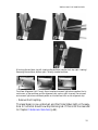
1
Operating Instructions
easyScan 2 AFM
Version 1.3
‘NANOSURF’ AND THE NANOSURF LOGO ARE TRADEMARKS OF NANOSURF AG, REGISTERED AND/OR OTHERWISE PROTECTED IN VARIOUS COUNTRIES.
© SEPTEMBER 05 BY NANOSURF AG, SWITZERLAND, PROD.:BT02089, V1.3R0
3
Table of contents
The easyScan 2 AFM
7
Features.................................................................................................8
easyScan 2 Controller
8
AFM Measurement
10
Components of the System .................................................................12
Contents of the Tool set
14
Connectors, Indicators and Controls ...................................................15
The Scan head
15
The Controller
16
Installing the easyScan 2 AFM
18
Installing the Hardware ........................................................................18
Installing the Basic AFM Package
19
Installing the AFM Video Module
20
Installing the Signal Module: S
20
Installing the Signal Module: A
20
Turning on the Controller
20
Storing the Instrument .........................................................................21
Installing the Software .........................................................................22
Step 1 - Installation of hardware drivers
23
Step 2 - Installation of the easyScan 2 software
24
Step 3 - Installation of DirectX 9
25
Installing the software on different computers
25
Installing the drivers for the AFM Video Module
25
Preparing for Measurement
27
Initialising the Controller ......................................................................27
Installing the cantilever ........................................................................28
Selecting a cantilever
28
Inserting the cantilever in the Scan head
29
Installing the sample ............................................................................32
Preparing the Sample
32
Stand-alone measurements
33
The sample stage
33
Mounting a sample onto the sample holder
34
A First Measurement
36
Running the microscope simulation.....................................................36
Preparing the instrument .....................................................................37
Entering values in the control panels
37
Approaching the sample ......................................................................39
1. Manual Coarse approach
40
4
2. Manual approach using the approach stage
40
3. Automatic final approach
41
Starting a measurement ......................................................................43
Selecting a measurement area............................................................44
Storing the measurement ....................................................................46
Creating a report..................................................................................46
Finishing ..............................................................................................47
Improving measurement quality
48
Removing interfering signals ...............................................................48
Judging measurement quality..............................................................49
Adjusting the measurement plane .......................................................50
Measurement modes
54
Static Force..........................................................................................54
Dynamic Force.....................................................................................55
Phase Contrast ....................................................................................55
Phase measurement
57
Force Modulation .................................................................................58
Spreading Resistance..........................................................................59
The Signal Modules
61
Signal Module: S..................................................................................61
Signal Module: A..................................................................................62
Using the User Inputs and Outputs
64
Maintenance
65
Scan head
Scan electronics
Problems and Solutions
65
65
66
Probe Status light blinks red
66
Image quality suddenly deteriorates
66
No connection to microscope
67
USB Port error
67
Nanosurf support .................................................................................68
Self help
68
Assistance
68
AFM Theory
70
Scanning Probe Microscopy ................................................................70
The Nanosurf easyScan 2 AFM...........................................................71
5
TABLE OF CONTENTS
About this Manual
This manual gives instructions on how to set up and use your Nanosurf
easyScan 2 AFM system. Installing the easyScan 2 AFM should be read when
installing your easyScan 2 AFM system. The chapters Preparing for Measurement and A First Measurement should be read by all users, because they
contain useful instructions for everyday measurements. The other chapters
give more information for advanced or interested users. Those who need a
more detailed description of the functions of the easyScan 2 software
should refer to the Software Reference manual.
6
The easyScan 2 AFM
The Nanosurf easyScan 2 AFM is an atomic force microscope system that
can make nanometer scale resolution measurements of topography and several other properties of a sample. The easyScan 2 AFM system is a modular
scanning probe system that can be upgraded to obtain more measurement
capabilities. The main parts of the basic system are the easyScan 2 AFM
scan head, the AFM Sample stage, the easyScan 2 Controller with AFM
Basic module, and the easyScan 2 software. At the time of publication, the
following parts can be used with the easyScan 2 system:
• STM Scan Head: makes atomic scale measurements. Refer to the easyScan 2 STM Operating Instructions for more details.
• AFM Dynamic Module: adds dynamic mode measurement capabilities
for measuring delicate samples.
• AFM Mode Extension Module: adds phase contrast, force modulation
and current measurement capabilities.
• AFM Video Module: allows observation of the approach on the computer screen. This is especially useful when observation using the lenses is
impractical.
• Signal Modules: allow monitoring signals (Module: S) and creating custom measurement modes (Module: A). Refer to chapter The Signal Modules (p.61) for more details.
• Micrometre Translation Stage: for reproducibly finding a specific position on the sample.
• Nanosurf Report: software for detailed measurement analysis and automatic report generation.
• Scripting Interface: software for automating measurements. Refer to the
Software Reference and Programmer’s Manual for more details.
• TS-150 active vibration isolation table: reduces the sensitivity of the
instrument to vibrations in its environment.
7
THE EASYSCAN 2 AFM
Features
easyScan 2 Controller
Electronics
Electronics size / weight
Power supply
Computer interface
Integrated USB hub
Measurement channels
470 x 120 x 80mm / 2.4kg
90 - 240V~/ 30W 50/60Hz
USB 1.1
2 Ports (100mA max)
16bit A/D converters, up to seven signals
depending on mode.
Scan generator
16bit D/A converter for all axes
Scan speed
Up to 60ms/line at 128 datapoints/line
Scan drive signals
No (dangerous) high voltage
Scan area and data points Individual width/height, up to 2048 x 2048
points
Scan image rotation
0 - 360°
Sample tilt compensation Hardware X/Y-slope compensation
Spectroscopy modes
Single point measurement or multiple measurements along vector
Spectroscopy measurement 1 - 255
averaging
Spectroscopy data points
Up to 2048
Software
Simultaneous display of
data in charts types
User profiles
On-line processing functions
Quick evaluation functions
Data export
8
Line graph, Color map, 3D view, …
Customisable display and parameter settings
Mean fit, Polynomial fit, Derived data, …
distance, angle, cross section, roughness, …
BMP, ASCII, CSV, …
FEATURES
Computer requirements
Operating system
Electronics interface
Recommended PC hardware
Windows 2000, XP or newer
USB port
Pentium 4/M or AMD Athlon, 256MB
RAM, True color 1024x786 video card,
HW Open GL accelerator
Computer not included with system.
Nanosurf easyScan 2 Scripting Interface
Applications
Included control software
Remote control by
Automating measurement tasks, lithography, custom evaluation functions, using
third party measurement equipment
Windows Scripting Host: Visual Basic
Script, Java Script, …
COM compatible languages: LabView,
MathLab, Visual Basic, Delphi, C++, …
Nanosurf easyScan 2 Signal Module: S
Available output signals
Full scale corresponds to
Power supply output
X-Axis, Y-Axis, Z-Axis, Approach, Tip Voltage, STM Current or AFM Deflection,
Excitation, Amplitude, Phase
±10V, Excitation: ±5V
GND, +15V, -15V
Nanosurf easyScan 2 Signal Module: A
Output signal
Additional analog user outputs
Synchronisation output
All output signals of Signal Module: S
2x 16bit D/A converters, ±10V
1x TTL: start, end, point sync pulses, variable width
Additional signal modulation X-Axis, Y-Axis, Z-Axis, Tip Voltage, Excitainputs
tion
Free connectors
2x Aux, connection made on user request
Modulation range
±10V, Excitation: ±5V
9
THE EASYSCAN 2 AFM
Additional analog user inputs 2x 16bit A/D converters, ±10V
Additional modes
Almost unlimited
User inputs can optionally be measured in all Imaging and Spectroscopy
modes.
User outputs can be modulated in Spectroscopy measurements.
AFM Measurement
AFM Scan Head:
range 1)
Maximum Scan
Maximum Z-range
Drive resolution
Z 2)
10µm
10µm
70µm
70µm
110µm
110µm
2µm
0.027nm
14µm
0.21nm
22µm
0.34nm
0.15nm
1.1nm
1.7nm
Drive resolution XY 2)
XY-Linearity Mean Error
<0.6%
<1.2%
<0.6%
Z measurement noise level
0.07nm
0.6nm
0.4nm
(RMS, Static Mode)
(max. 0.2nm) (max. 0.8nm) (max. 0.55nm)
Z measurement noise level
0.04nm
0.5nm
0.3nm
(RMS, Dynamic Mode)
(max. 0.07nm) (max. 0.8nm) (max. 0.55nm)
1) Manufacturing tolerances are ±15% for 10µm and 70µm heads, ±10%
for 110µm scan heads. The exact values are given on the calibration certificate delivered with the instrument.
2) Calculated by dividing the maximum range by 16bits
Design
Tripod stand-alone
Sample size
Unlimited
Automatic approach range
5mm
Max. approach speed
0.1mm/s
Alignment of cantilever
Automatic adjustment
Electrical connection to tip
Available
Scan head weight
350g
Sample observation optics
Dual lens system (top/side view)
Optical magnification
Top x12 / side x10
10
FEATURES
View field
Sample illumination
Top 4x4mm / side 5x3mm
White LEDs (brightness 0-100%)
Compatible cantilevers
Manufacturers
Static modes
Dynamic modes
Spreading Resistance mode
Available tips
Typical static load
Typical dynamic frequency
NanoSensors® and NanoWorld®
(www.nanoworld.com)
CONTR, LFMR, ZEILR
NCLR, ZEIHR, EFM, MFMR
CONTPt, NCLPt, CDT-NCLR
Standard, SuperSharp Silicon,
HighAspectRatio, Diamond
10nN
190kHz
AFM Basic Module
Imaging modes
Spectroscopy modes
Tip voltage
Static Force (Contact): Const. Force (Topography), Const. Height (Deflection)
Force-Distance, Force-Tip voltage
±10V in 5mV steps
The AFM Basic Module is required for using AFM Scan Heads.
AFM Dynamic Module
Additional imaging modes
Dynamic Force (Intermittent Contact,
etc.): Const. Amplitude (Topography),
Const. Height (Amplitude)
Amplitude-Distance
Additional spectroscopy
modes
Dynamic frequency range
15kHz - 300kHz
Dynamic frequency resolution < 0.1Hz
The AFM Basic Module is required for using the AFM Dynamic Module.
AFM Mode Extension Module
Additional imaging modes
Phase Contrast, Force Modulation, Spreading Resistance
11
THE EASYSCAN 2 AFM
Additional spectroscopy
Phase-Distance, Current-Voltage, Currentmodes
Distance etc.
Phase contrast range
± 90°
Phase contrast resolution
< 0.05°
Phase reference range
0 - 360°
Tip current measurement
± 100µA, 3nA resolution
Both the AFM Basic Module and the AFM Dynamic Module are required
for using the AFM Mode Extension Module.
AFM Video Module
Camera system
Magnification
View field
Image pixels
Video display
Analog video output
Dual video (top/side view)
Top 100x / side 70x
Top 3.2 x 2.7mm / side 4.1 x 3.4mm
352x288
In control software, can be saved as JPEG
PAL Video-S
Micrometre Translation Stage
X-Y resolution
Travel
< 0.5µm
13mm
Components of the System
This section describes the parts that may be delivered with an easyScan 2
AFM system. The contents of delivery can vary from system to system,
depending on which parts were ordered. To find out which parts are
included in your system, refer to the delivery note shipped with your system. Some of modules listed in the delivery note are built into the Controller. Their presence is indicated by the status lights on the top surface of the
Controller when it is turned on (section Connectors, Indicators and Controls
(p.15)).
1. easyScan 2 Controller with a built in AFM Basic Module, and optionally with built in AFM Dynamic Module, AFM Mode Extension Module, Video Module electronics and Signal Module A or S electronics
12
COMPONENTS OF THE SYSTEM
1
4
2
5
3
7
6
18
12
13
17
19
Components: The easyScan 2 AFM system
2. USB cable
3. Mains cable
4. easyScan 2 AFM Scan head(s) with AFM Video Camera (with AFM
Video Module)
5. Scan head case
6. Scan head cable
7. Video Camera cable (with AFM Video Module)
8. AFM calibration certificate
9. This easyScan 2 AFM Operating Instructions manual
10. easyScan 2 Software Reference manual
11. easyScan 2 Installation CD: Contains software, calibration files, and
PDF files of all manuals
12. AFM Tool set (option). The contents of the AFM Tool set are
described in the next section.
13
THE EASYSCAN 2 AFM
13. AFM Sample Stage (option)
14. Micrometre Translation Stage (option)
15. User's Guide; Translation Stage, Model: 9064 (with Micrometre
Translation Stage)
16. Positioning Tool Set (with Micrometre Translation Stage)
17. Break-out cable (with Signal Module: S)
18. Connector box (with Signal Module: A)
19. Signal Module cables (2x) (with Signal Module: A)
20. Scripting Interface Certificate of purchase with Activation key printed
on it (with Scripting Interface)
21. Instrument Case
The package may also contain easyScan 2 STM head(s) and modules for the
STM, which are described in the STM Operating Instructions
Contents of the Tool set
The contents of the Tool set depends on the available modules. It may
contain:
1
2
3
4
5
9
8
7
6
10
Contents of the AFM Tool set
1. Ground cable
2. Protection feet
3. Pointed tweezers: 3SCA-SL
14
11
12
CONNECTORS, INDICATORS AND CONTROLS
4. Screwdriver, 2.3 mm
5. Cantilever insertion tool (usually mounted in DropStop
6. DropStop)
7. Sample holder (with AFM Sample Stage)
8. AFM Basic Sample Kit (option) with CD-ROM Sample, Microstructure sample
9. AFM Calibration Samples Kit (option) with Calibration grid: 10 µm/
100nm, Calibration grid: 660nm, Flatness sample
10. Set of 10 CONTR cantilevers (option)
11. Set of 10 NCLR cantilevers (option)
12. USB dongle for the Nanosurf Report software (option)
Connectors, Indicators and Controls
Use this section to find the location of the parts of the easyScan 2 AFM that
are referred to in this manual.
The Scan head
Levelling
screws
Scan head
serial number
Socket for Cantilever
insertion tool
Camera
connector
Ground
connector
Spiral cable
connector
Cantilever on
Alignment chip
Parts of the scan head: Scan head with video camera
15
THE EASYSCAN 2 AFM
The Controller
Module lights
Scan Head lights
Probe Status light
Video Out
connector Video In
(optional) connector
(optional)
Signal Out
connector
(optional)
Signal In
connector
(optional)
Scan head
cable connector
Controller
Serial number
Power
switch
S/N: 23-05-001
USB outputs
(to dongle)
USB active
light
Mains power
connector
USB input
(from PC)
USB power
light
The easyScan 2 Controller
Status lights
All status lights on top of the Controller will light up for one second when
the power is turned on.
The Probe Status light
Indicates the status of the Z-Feedback loop. It can indicate the following
statuses:
red
The scanner is in its upper limit position. This occurs
when the tip-sample interaction is stronger than the
set point for some time. There is danger of damaging
the tip due to too high an interaction.
orange/yellow
16
The scanner is in its lower limit position. This occurs
when the tip-sample interaction is weaker than the set
CONNECTORS, INDICATORS AND CONTROLS
point for some time. The tip is probably not in contact
with the sample surface.
green
The scanner is not in a limit position, and the feedback loop can measure the sample surface.
blinking green
The feedback loop has been turned off in the software.
blinking red
There is no signal with which to do feedback: The
light intensity on the photodetector of the laser beam
deflection system is too low. Refer to section Probe
Status light blinks red (p.66)) for more information.
The Scan Head lights
Indicate the scan head type that is connected to the instrument. The Scan
head lights blink when no scan head can be detected, or when the Controller has not been initialised yet.
The Module lights
Indicate the modules that are built in into the Controller. The module
lights blink when the Controller has not been initialised yet. During initialisation, the Module lights are turned on one after the other.
17
INSTALLING THE EASYSCAN 2 AFM
Installing the easyScan 2 AFM
The following sections describe the installation of the easyScan 2 AFM.
Important!
To make high quality measurements, the following precautions must be
taken to keep equipment clean:
• Never touch the cantilever tips, the cantilevers (figure Contents of the
AFM Tool set (p.14), 10, 11), or the open part of the Scan head (figure
Cantilever deflection detection system (p.29)).
• Ensure that the surface to be measured is free of dust and possible residues.
• Always secure the Scan head by putting it in the Scan head case during
transport and storage (figure Scan head storage).
Scan head storage: Scan head stored in Scan head case
Installing the Hardware
Important!
- Ascertain that the mains connection is protected against excess voltage
surges.
- Place the instrument on a stable support in a location that has a low level
of building vibrations, acoustic noise, electrical fields and air currents.
18
INSTALLING THE HARDWARE
It is recommended to cover the instrument with a box to shield it from near
infrared light from artificial light sources, because this light may cause noise
in the cantilever deflection detection system. If the vibration isolation of
your table is insufficient for your measurement purposes, an optional active
vibration isolation table is available.
easyScan 2 AFM system: System with Sample stage, Micrometre Translation Stage, AFM Video
Module and Signal module: A
Installing the Basic AFM Package
- Attach the Scan head cable (figure Components (p.13), 6) to the Scan head
(Components, 4) using the screwdriver (figure Contents of the AFM Tool
set (p.14), 4).
- Connect the Scan head cable (Components, 6) to the Controller (Components, 1).
The scan head cable has a helix shape in order to isolate the Scan head from
vibrations of the table it is standing on. Take care that it is lying loosely on
the table to ensure proper operation, and avoid stretching it.
- Connect the USB cable (Components, 2) to a free USB port on your computer, but do not connect it to the easyScan 2 Controller yet. If you have
inadvertently done this anyway, continue with section Installing the Software (p.22).
19
INSTALLING THE EASYSCAN 2 AFM
Installing the AFM Video Module
- Connect the Video Camera cable to the connector on the AFM Video
Camera (Components, 4) and the Video In connector on the Controller
(figure The easyScan 2 Controller (p.16)).
In case of an upgrade, both the scan head and the Controller must be sent
in to your local Nanosurf distributor for mounting the Video Camera on
the Scan Head and installing the Video Camera electronics in the Controller. After the Controller has been returned, you should install the drivers for
the AFM Video Module (section Installing the drivers for the AFM Video
Module (p.25)).
Installing the Signal Module: S
- Connect the Break-out cable (Components, 17) to the Signal Out connector on the Controller (figure The easyScan 2 Controller).
In case of an upgrade, the Controller must be sent in to your local Nanosurf
distributor for mounting the Signal Module: S electronics in the Controller.
Installing the Signal Module: A
- Connect one Signal Module cable (Components, 19) to the Signal Out
connector on the Controller and to the Output connector on the Signal
Module: A.
- Connect the other Signal Module cable to the Signal In connector on the
Controller and to the Input connector on the Signal Module: A.
In case of an upgrade, the Controller must be sent in to your local Nanosurf
distributor for mounting the Signal Module: A electronics in the Controller.
Turning on the Controller
- Connect the easyScan 2 Controller (Components, 1) to the mains using
the mains cable (Components, 3) and turn it on.
20
STORING THE INSTRUMENT
Warning!
This product contains a
Class 1 Laser
Invisible laser radiation!
The laser is located behind the cantilever.
Although the optical power should do no damage when the instrument
is assembled, avoid looking directly into the laser beam.
Laser source information:
Wavelength: 830nm
Optical power: <0.4mW
Class one Laser
First all status lights on top of the Controller briefly light up. Then the Scan
Head lights and the lights of the detected modules will start blinking, and
all other status lights turn off. The status lights remain blinking until the
Controller is initialised by starting the easyScan 2 software.
Storing the Instrument
If you have to send in the instrument, transport it or if you are not using it
for some time, please pack it in the shipping package or instrument case, so
that the instrument is protected from dust.
- Turn off the instrument as described in section Finishing (p.47), and
remove all cables.
- Pack all components as shown in figure Packing.
Important!
Before transport, always close the protective cover of the scan head, and put
the instrument in the original Nanosurf shipping box or Instrument Case.
21
INSTALLING THE EASYSCAN 2 AFM
Packing: The easyScan 2 AFM system packed in the Instrument Case
Installing the Software
- Check that the computer on which you want to install the software fulfils
the requirements listed in section Computer requirements (p.9).
- Disconnect the USB cable from the Controller.
- Turn on your computer and start Windows.
Important!
Make sure you have administrator privileges before software installation.
Do not run any other program while installing the scan software.
- Insert the easyScan 2 Installation CD into the CD drive of the computer.
22
INSTALLING THE SOFTWARE
The setup program should start automatically. If this does not happen, proceed as follows:
- Open the easyScan 2 Installation CD.
- Start the program ‘StartCDMenu.exe’.
- Click ‘Full Installation of Nanosurf easyScan 2’.
The installation program will now start installing all components of the
Nanosurf easyScan 2 AFM: The hardware drivers, the easyScan 2 software,
DirectX 9.
- Follow the instructions given by the setup program.
Step 1 - Installation of hardware drivers
The Nanosurf hardware needs instrument drivers for the USB hub, the
USB interface and the AFM Video Module. These are installed first.
- Connect the USB cable to the easyScan 2 Controller.
The red USB power light on the Controller should now light up, and the
PC should now automatically detect that new devices have been connected
to it, and start installing the drivers. On some computers, the detection and
installation process may take some time (20 seconds or more), please be
patient. Once all the drivers listed below have been installed, click OK in
the Step 1 Dialog.
If you have already installed the easyScan 2 software or the Mobile S software on this computer, it is possible that nothing will happen, because the
drivers are installed already. In this case the drivers listed below should be
displayed in the Windows device manager. If this is the case, you can also
click OK in the Step 1 Dialog.
Standard-USB-hub
The operating system should first find the ‘Standard-USB-hub’, and install
its driver. The installation order of the other drivers may vary.
High Speed Serial Converter
When the operating system finds the ‘USB <-> serial interface’, it asks what
to do:
23
INSTALLING THE EASYSCAN 2 AFM
- Choose ‘Automatic installation’.
- Click the default choice in all dialogs.
The USB High Speed Serial Converter is now installed.
USB Serial Port
When the operating system finds the ‘USB Serial Port’, it asks what to do:
- Select ‘Automatic installation’.
- Click the default choice in all dialogs.
The USB Serial Port is now installed.
USB Video Adapter
The USB Video Adapter driver is only installed if the Controller contains
a Video Module. When the operating system finds the ‘USB Device’, it
asks what to do to install the ‘USB Video Adapter’:
- Select ‘Automatic installation’.
During installation of the video adapter under windows XP, windows may
notify you that the driver is not digitally signed. If this happens:
- Click ‘Continue installation’.
- Click the default choice in all other dialogs.
Repeat Step 1 for all USB ports of the PC, in order to ensure that the instrument works when connecting the Controller to a different PC USB port.
Step 2 - Installation of the easyScan 2 software
- Click the default choice in all dialogs.
The setup program will ask for the directory in which the easyScan 2 software is to be installed.
- Install the software in the proposed directory, unless the ‘Program Files’
directory has a different name in your language of the Windows operating system.
24
INSTALLING THE SOFTWARE
Important!
The easyScan 2 AFM Installation CD contains calibration information
(.hed files) specific to your instrument, therefore you should keep (a backup
copy of) the CD delivered with the instrument.
Step 3 - Installation of DirectX 9
The easyScan 2 software needs DirectX 9 or newer for correct operation.
Click the default choice in all dialogs.
- After installing DirectX 9, the computer may have to re-boot.
Installing the software on different computers
You can install the easyScan 2 software on a different computer than the
one that controls the measurement, for example for running the microscope simulation, or for off-line data analysis. Please note:
• In order to use the Controller, the hardware drivers and DirectX 9 must
be installed on the computer to which it is connected.
• The Controller and its drivers must be installed when installing the
Nanosurf Scripting Interface.
Installing the drivers for the AFM Video Module
When the AFM Video Module is added to your Controller after you have
installed the software, its drivers must be installed before it can be used:
- Disconnect the USB cable from the Controller.
- Turn on your computer and start Windows.
Important!
Make sure you have administrator privileges before software installation.
- Insert the easyScan 2 Installation CD into the CD drive of the computer.
- If the setup program has started automatically, click ‘Exit’.
- Connect the USB cable to the easyScan 2 Controller.
25
INSTALLING THE EASYSCAN 2 AFM
The red USB power light on the Controller should now light up, and the
PC should now automatically detect the ‘USB Device’, and asks what to do
to install the ‘USB Video Adapter’. On some computers, the detection and
installation process may take some time (20 seconds or more), please be
patient.
- Select ‘Automatic installation’.
During installation of the video adapter under windows XP, windows may
notify you that the driver is not digitally signed. If this happens:
- Click ‘Continue installation’.
- Click the default choice in all other dialogs.
Connect the USB cable to all USB ports of the PC, in order to ensure that
the instrument works when connecting the Controller to a different PC
USB port.
26
INITIALISING THE CONTROLLER
Preparing for Measurement
This chapter describes actions that you perform on a day-to-day basis as a
preparation for your measurements, when the instrument has already been
set up according to the instructions in chapter Installing the easyScan 2 AFM
(p.18). These steps are changing the cantilever, selecting a sample stage, and
preparing the sample.
Initialising the Controller
- Check that the easyScan 2 Controller is connected to the mains power,
and the USB port of the control computer.
- Turn on the power.
First all status lights on top of the Controller briefly light up. Then the Scan
Head lights and the lights of the detected modules will start blinking, and
all other status lights turn off.
- Start the easyScan 2 software on the control computer.
The main program window appears, and all status lights are turned off.
Now a Message ‘Controller Startup in progress’ is displayed in the software,
and the module lights are turned on one after the other. When initialisation
is completed, a Message ‘Starting System’ is shortly displayed in the software and the Probe Status light, Scan Head status light of the detected scan
head and modules will light up. If no scan head is detected, both scan head
status lights blink.
- Determine which operating mode you wish to use.
- Refer to the sections on Operating modes in this manual for the properties of the various operating modes. To change the operating mode:
- Click
in the Navigator to open the Operating mode panel.
- Select the operating mode using the Operating mode drop-down menu.
27
PREPARING FOR MEASUREMENT
Installing the cantilever
To maximise ease of use, the Nanosurf easyScan 2 AFM is designed so that
the cantilever can be installed and removed without having to readjust the
cantilever deflection detection system. This is possible because an alignment system is used that consists of an alignment chip and matching
grooves in the back side of the cantilever chip. This positions the cantilever
with micrometer accuracy (see figure Cantilever, left). Note though, that
Cantilever: left: alignment system, centre: Cantilever chip viewed from the top, right cantilever
450 µm long, 50 µm wide with integrated tip.
this accuracy is only guaranteed when the cantilever and the mounting chip
are absolutely clean. Installation of the cantilever should therefore still be
carried out with great care because good results depend strongly on the
accuracy of this process.
Selecting a cantilever
Now select the proper cantilever type for the measurement mode you wish
to use. The stiffer, short NCLR cantilever is generally used for the dynamic
28
INSTALLING THE CANTILEVER
Sample illumination
Cantilever
Photodetector
Cantilever
holder spring
Laser
Alignment chip
Hole for cantilever
insertion tool
Cantilever deflection detection system
operating mode; the more flexible, long CONTR cantilever is generally
used for the static operating mode.
When you change to a different cantilever type:
- Select the cantilever type using the ‘Mounted cantilever’ drop-down
menu in the Operating mode panel.
Presently, only cantilevers from the companies NanoWorld and NanoSensors can be used. The various usable types are listed in section Compatible
cantilevers (p.11).
Inserting the cantilever in the Scan head
Important!
• Nothing should ever touch the cantilever, especially the tip end!
• The Cantilever Holder Spring (see figure Cantilever deflection detection
system) is very delicate and should not be bent!
• Always close the DropStop before handling the cantilever. Otherwise, the
cantilever may fall into the scan head. This may cause malfunction of the
microscope, particularly the scanner.
• If a cantilever has dropped into the scan head, and the microscope is malfunctioning, contact your local support. Never open the scan head,
because this is likely to cause damage to the scanner and the laser beam
deflection detection system.
To insert the cantilever:
- Remove the Cantilever Insertion tool from the DropStop
29
PREPARING FOR MEASUREMENT
- Turn the scan-head upside-down.
- Close the DropStop (figure Closing the DropStop).
Closing the DropStop
The laser beam is now blocked by the DropStop. As a consequence, the
Probe Status light on the easyScan 2 Controller will now blink red.
- Place the cantilever insertion tool (figure Contents of the AFM Tool set
(p.14), 5) into the hole behind the alignment chip (figure Mounting the
cantilever, top left). The Cantilever Holder Spring opens.
- Use the tweezers to remove the old cantilever from the instrument (figure
Mounting the cantilever, top right).
It is recommended to always store the Scan head with a cantilever installed.
- Take the new cantilever out of its box. The cantilever is now oriented face
up.
- Let the cantilever carefully fit into the alignment chip in the Scan head
(figure Mounting the cantilever, top right).
- Verify that the cantilever does not move with respect to the alignment
chip when lightly tapping it with the tweezers.
If the cantilever does move, it is probably not inserted correctly. Refer to
figure Cantilever Alignment for the correct alignment and examples of
incorrect alignment.
- Gently pull the cantilever insertion tool out of the hole; the cantilever
holder spring closes and holds the cantilever chip tightly in position (figure Mounting the cantilever, bottom right).
30
INSTALLING THE CANTILEVER
Mounting the cantilever: top left: Inserting the cantilever insertion tool; top right: Inserting/
Removing the cantilever; bottom right: Correctly inserted cantilever
Cantilever Alignment: left: Correct, the mirrored environment light shows a pattern that is
continuous on the cantilever and the alignment chip; centre, right: Incorrect, the mirrored
environment light shows a different pattern on the cantilever than on the alignment chip.
- Remove the DropStop.
The laser beam is now unblocked, and the Probe Status light on the easyScan 2 Controller should now stop blinking red. If this is not the case refer
to Chapter Problems and Solutions (p.66).
31
PREPARING FOR MEASUREMENT
Installing the sample
Preparing the Sample
The easyScan 2 AFM can be used to examine any material with a surface
roughness that does not exceed the height range of the scanning tip. Nevertheless the choice and preparation of the surface can influence the surfacetip interaction. Examples of influencing factors are excess moisture, dust,
grease etc. Because of this some of the samples need special preparation to
clean their surface. Generally, clean as little as possible.
If the surface is dusty, try to measure on a clean area between the dust. It is
possible to blow coarse particles away with dry, oil free air, but small particles generally stick so well to the surface that they can not be removed. Note
that bottled pressurised air is generally dry, but pressurised air from an inhouse supply is generally not. In this case an oil filter should be installed.
Blowing dust away by breath is not advisable, because it is not dry.
When the surface is contaminated with grease, oil or something else, the
surface should be cleaned with a solvent. Suitable solvents are distilled or
demineralised water, alcohol or acetone, depending on the contaminant.
The solvent should be very pure, in order to prevent the collection of impurities on the surface when the solvent evaporates. The sample should be
cleaned several times to remove dissolved and redeposited contaminants if
it is very contaminated. Delicate samples can be cleaned in an ultrasound
bath.
Basic Sample Kit
The Basic Sample Kit contains a CD sample and a Microstructure sample.
They can be used for determining if the instrument is functioning normally.
The microstructure sample consists of holes in a silicon oxide layer with an
unspecified period and depth. At the time of writing, the approximate
period is 10µm, the approximate depth is 100nm.
The CD sample is a piece from a CD, without any coating applied to it.
Both samples should be kept in their box. Then it should be unnecessary to
clean them. Cleaning is not advisable, because the grid is rather delicate.
32
INSTALLING THE SAMPLE
Calibration Sample Kit
The samples supplied in the optional Calibration Sample kit are meant as
test samples that can also be used to check the correctness of the instrument’s calibration. Certified Calibration grids are available as an option.
The Calibration grid: 10 µm/100 nm can be used for testing the xy-calibration of the 70µm and 100µm scanners and for testing z-calibration. It is
manufactured using a standard silicon process that produces silicon oxide
squares on a silicon substrate. It has a period of 10 µm and a square height
of approximately 100 nm.
The Calibration grid: 660 nm can be used for testing the xy-calibration of
the 10µm scanner. It consists of holes in a silicon oxide layer with a period
of 660 nm and an unspecified depth. At the time of writing, the approximated depth is 149 nm.
The exact period and height of the Calibration grid structure (with 3%
accuracy) are given on the box in which they are stored.
The Flatness sample is a polished silicon sample. It can be used for testing
the Flatness of the scanned plane.
The calibration samples should be kept in their box. Then it should be
unnecessary to clean them. Cleaning is not advisable, because the samples
are rather delicate.
Stand-alone measurements
You can either use the instrument with the sample stage, or as a stand-alone
instrument. The sample stage offers vibration isolation, and a stable scan
head mount. Therefore, operate the instrument as a stand-alone only when
the sample is too large for the sample stage. For stand-alone measurements,
put the Scan head directly on top of the sample. Protection feet for under
the three alignment screws are provided to protect delicate samples from
being scratched (figure Contents of the AFM Tool set (p.14), 2).
The sample stage
The sample stage (figure Components (p.13), 13) offers vibration isolation
and stable positioning and can be used to comfortably position the sample.
An optional micrometre translation stage for X-Y positioning can be
33
PREPARING FOR MEASUREMENT
mounted on the sample stage. You can either put the sample directly on the
sample stage, or mount it on the sample holder (figure Contents of the AFM
Tool set (p.14), 6).
Scan head on the Sample Stage
Mounting a sample onto the sample holder
The simplest way to do this is to use put the sample on the sticky side of a
Post-it® note that is attached to the sample holder using double sided adhesive tape.
Sample mounted onto the sample holder
It is recommended to always connect the sample holder to the ground connector on the scan head using the grounding cable (figure Contents of the
AFM Tool set (p.14), 1).
34
INSTALLING THE SAMPLE
Important!
Avoid all mechanical impact on the cantilever when placing the sample
holder under the Scan head. Any impact will damage the tip.
35
A FIRST MEASUREMENT
A First Measurement
In this chapter, step by step instructions are given as to how to operate the
microscope and make a simple measurement. More detailed explanations
of the software and the system are given in the Software Reference manual.
Running the microscope simulation
You can start the easyScan 2 software without having the microscope connected to your computer in order to explore the easyScan 2 system (measurements and software) without danger of damaging the instrument or the
cantilever. In the simulation mode, most functions of the real microscope
are emulated. The sample is replaced by a mathematical description of a
surface.
When you start the easyScan 2 software when no microscope is connected
to your PC, the following dialog appears:
- Click ‘OK’.
The status bar will now display the text ‘Simulation’.
You can also switch to the simulation mode with the microscope connected:
- Select the menu entry ‘Options>Simulate Microscope’.
A check will now be displayed in front of the menu entry.
To exit the Microscope simulation mode:
- Select the menu entry ‘Options>Simulate Microscope’ again.
The check in front of the menu entry is now removed, and the status bar
will now display the text ‘Online’.
36
PREPARING THE INSTRUMENT
Preparing the instrument
Important!
• Never touch the cantilever or the surface of the sample! Good results rely
heavily on a correct treatment of the tip and the sample.
• Avoid exposing the system to direct light while measuring. This could
influence the beam deflection detector and reduce the quality of the
measurement.
Prepare the instrument as follows (see chapter Preparing for Measurement
(p.27) for more detailed instructions):
- If you have the AFM Dynamic Module, install an NCLR type cantilever,
otherwise install an CONTR type cantilever.
- Install one of the samples from the Nanosurf AFM Basic sample kit or
Calibration sample kit. Preferably install the 10 µm Calibration grid
when using a 70µm or 110µm scan head and the 660 nm Calibration grid
when using a 10µm scan head.
The measurement examples shown here were made with the 10 µm Calibration grid.
To make sure that the configuration is correct, do the following:
- Open the User interface dialog via the menu ‘Options/Config User Interface...’.
- Select the ‘Easy level’ user interface mode.
- Open the menu item ‘File>Parameters>Load...’, and load the file
‘Default_EZ2-AFM.par’ from the directory with default easyScan 2
AFM configurations. Usually this is ‘C:\Program Files\Nanosurf\Nansurf easyScan 2\Config’.
Entering values in the control panels
To change a parameter in any panel, use on of the following methods:
• Activate the parameter by clicking it with the mouse pointer, or by select37
A FIRST MEASUREMENT
ing it with the Tab key.
• The value of an activated parameter can be increased and decreased using
the up and down arrow keys on the keyboard. The new value is automatically used after one second.
• The value of a numerical parameter can also be increased and decreased
by clicking the arrow buttons with the mouse pointer. The new value
is automatically used after one second.
• The value of an active numerical parameter can also be entered using the
keyboard.
The entered value is used on pressing the ‘Enter’ or ‘Return’ key, or by
activating another input.
The entered value is discarded on pressing the ‘Esc’ key.
Type the corresponding character to change the unit prefix:
prefix
femto
pico
nano
micro
milli
keyboard key
f
p
n
u
m
prefix
no prefix
kilo
mega
giga
tera
keyboard key
space bar
k
shift - M
shift - G
shift - T
Unit prefixes with corresponding character
For example, if the basic unit is Volts, type ‘m’ to change to millivolts,
type the space bar for volts, type ‘u’ for microvolts.
• The selection of a drop-down menu (e.g.:
) can be
changed using the mouse or the up and down arrow keys on the keyboard.
Sometimes the program will change an entered parameter value to a slightly
different value. This happens when the desired value is outside the range
that the easyScan 2 Controller can handle, for example due to the resolution limits or timing limits. The desired value is automatically changed to
the nearest possible value.
38
APPROACHING THE SAMPLE
Approaching the sample
To start measuring, the tip must come within a fraction of a nanometer of
the sample without touching it with too much force. To achieve this, a very
careful and sensitive approach of the cantilever is required. This delicate
operation is carried out in three steps: Manual coarse approach, manual
approach using the approach stage, and the automatic final approach. The
colour of the probe status light on the Controller shows the status of the
approach:
orange
Normal state during approach, the Z-scanner is fully
extended toward the sample.
red
The approach has gone too far, the tip was driven into
the sample, and the Z-scanner is fully retracted away
from the sample. In this case, the tip is probably damaged, so you will have to start over again with installing a new tip.
green
The approach is finished, the Z-scanner is within the
measuring range.
The approach is operated using the Positioning window. To open this window:
- Click the Positioning icon
in the Navigator.
Use the side view of the cantilever to judge the distance between tip and the
sample surface. To use the side view:
- If the AFM Video Module is installed, click
Video panel of the Positioning window.
in the
- If you do not have the Video Module, use the side view lens to observe
the sample instead.
Even if you do not have the Video Module, you can use the Top and Side
view switches to quickly change the illumination to a predetermined level.
39
A FIRST MEASUREMENT
The side view should look like figure Side view of the cantilever after manual
coarse approach. You can use the cantilever as a ruler to judge distances in
the views of the integrated optics.
Side view of the cantilever after manual coarse approach
1. Manual Coarse approach
In this step, the sample surface is brought within the range of the fine
approach stage.
- Use the three levelling screws (figure Parts of the scan head (p.15)) to lower
the Scan head so that the cantilever is within 1-2 mm of the sample. Take
care that the Scan head remains levelled parallel to the sample surface by
turning all screws approximately the same amount.
When the sample is reflective, the mirror image of the cantilever should
now be visible (figure Side view of the cantilever after manual coarse
approach). When the sample is not reflective, the shadow of the cantilever
may be visible. If neither a mirror image nor a shadow are visible, change
the light until it is visible, for example by adding a light source, or by shading the light from outside or from bright surfaces in the room.
2. Manual approach using the approach stage
In this step, the tip is brought as close to the sample surface as possible,
without running a risk of touching it. The closer the tip is, the less time the
automatic final approach takes.
- Observe the distance between tip and sample in the side view of the inte40
APPROACHING THE SAMPLE
grated optics. The tip should not come closer to the sample than a few
times the cantilever width. (figure View of the cantilever after manual
approach, left).
View of the cantilever after manual approach: left: side view, right: top view
- Whilst observing the tip sample distance, click and hold
the tip is close enough to the sample.
until
The sample should now be in focus. Now use the top view image to find a
suitable location to measure on. In the top view, the sample is seen from a
direction perpendicular to its surface (figure View of the cantilever after manual approach, right). To use the top view:
- If the Video Module is installed, click
panel.
in the Video
- If you do not have the Video Module, use the top view lens to observe the
sample instead.
If necessary, move the sample holder to find a suitable location that is free
of dust particles.
3. Automatic final approach
In the last step, the tip approaches the sample until the set point is reached.
First check that you are using the right operating mode and cantilever:
- Click
in the navigator to open the Operating Mode panel.
41
A FIRST MEASUREMENT
- If you are operating in Static Force mode, select a CONTR type cantilever.
In dynamic mode, the instrument will automatically determine the vibration frequency used in the dynamic mode. To do this, it uses a measurement of the cantilever vibration amplitude as a function of excitation
frequency. This measurement is not displayed when using the default settings. Nevertheless, it is instructive to see this measurement at least once.
To display the measurement:
- Open the User interface dialog via the menu ‘Options/Config User Interface...’.
- Select the ‘Standard level’ user interface mode.
- Enable ‘Display sweep chart’ in the Mode Properties section of the Operating mode panel.
- Click the ‘Set’ button.
The software will now perform a coarse and fine frequency sweep, and display the results (figure Fine frequency sweep). For more details on the frequency search procedure see Software Reference, section Operating mode
panel.
Fine frequency sweep: Cantilever vibration amplitude as a function of frequency.
Now restore the default settings:
- Disable ‘Display sweep chart’ in the Mode Properties section of the Operating mode panel.
42
STARTING A MEASUREMENT
- Select the ‘Easy level’ user interface mode.
Now check that the set point and the feedback speed are set properly:
- Click
in the Navigator to open the Z-Controller panel.
For Dynamic Force mode:
- Set ‘Set point’ to 50-70%.
For Static Force mode:
- Set ‘Set point’ to 10-20nN.
- Set ‘Loop gain’ to 1000-1500.
Now you can start the approach:
- Click
in the Approach panel.
The cantilever is moved towards the sample using the approach stage, with
the Z-Controller turned on. The motion continues until the Z-Controller
error becomes zero. From now on the distance between sample and tip is
controlled automatically by the electronics. A message ‘Approach done’
appears when the approach has been completed.
Starting a measurement
Now that the tip-sample interaction defined by Set point is flowing
between tip and sample you can start measuring:
- Click
to open the Imaging window.
The instrument was set to automatically start measuring after the automatic
approach. Two representations of the ongoing measurement are drawn in
the Imaging panel. One representation is a color coded height image, called
a Color map, the other is a plot of height as a function of X* position called
a Line graph. Watch the displays for a while until about a quarter of the
measurement has been measured. With the current setting, the software
automatically adjusts the contrast of the Color map, and height range of the
Line graph to the data that have been measured.
43
A FIRST MEASUREMENT
Reminder: Measurements on the micrometer/nanometer scale are very sensitive. Direct light, fast movements causing air flow and temperature variations near the Scan head can influence and disturb the measurement.
When the measurement contains large disturbances, or no two scan lines
are similar, stop measuring and reduce or eliminate the disturbances:
- Click
and follow the instructions of the chapter Problems and Solutions (p.66).
Selecting a measurement area
You have prepared your measurement so that the scan line in the centre of
the Line graph reproduces stably. After the measurement has been completed, the color map graph should look similar to the one shown below.
Zooming in on an overview measurement
Now zoom into an interesting part of the measurement:
- Activate the color map graph by clicking on it.
- Click
in the imaging toolbar. The mouse pointer becomes penshaped when moving over the color map, and the Tool Results panel is
displayed.
Select an interesting region by drawing a square with the mouse pointer:
44
SELECTING A MEASUREMENT AREA
- Click on one corner of the region using the left mouse button, and keep
the button pressed.
- Drag the mouse to the other corner of the region, and then release it.
The size and the position of the square are shown in the Tool result panel.
- Release the mouse button when the square’s size covers approximately
one period of the grid.
- Confirm the selection by double clicking the color map graph using the
left mouse button. Now the selection is enlarged to the whole display size.
You can abort the zoom function by clicking
again.
The microscope will now start measuring a single grid period. Once the
measurement is completed, you should get an image such as the one in
figure Zoomed measurement, left. The depression in the sample surface to
the sides of the structure is due to data filter used. To remove it, select the
data filter ‘Raw Data’ in the Data filter drop-down, indicated by the
icon in the Chart bar. The chart will now become similar to figure Zoomed
measurement, right.
Zoomed measurement: left: with line subtraction, right: without line subtraction.
45
A FIRST MEASUREMENT
Storing the measurement
When you are satisfied with your image and would like to keep it, you can
take a snapshot of it by clicking the
button. The behaviour of this
button depends on whether a measurement is in progress or not.
When a measurement is in progress, and
is activated, a copy of the
measurement is made to a measurement document after the measurement
is finished.
When the measurement is not in progress, a copy is made immediately.
If you would like to take the snapshot of the measurement as it appears
during the measurement without waiting to finish:
Stop the scanning by clicking
- Generate a snapshot by clicking
.
.
If you want to save the measurement document to your hard disk drive, for
example for loading it to Nanosurf Report:
- Activate the measurement document by clicking in its window, or by
selecting it in the ‘Windows’ menu.
- Select the menu ‘File\Save as...’. Select the folder and name where you
would like to store the measurement.
The stored measurements can now be loaded with the easyScan 2 AFM and
the Nanosurf Report software for later viewing, analysis and printing (see
also Software Reference manual).
Creating a report
The optional Nanosurf Report software can be used for evaluating the
measurement, and creating visually appealing reports. Here, we will just
start the software and create a basic report.
- Click
in the Navigator.
The Report software will now start, open the currently selected measurement in the report software, and evaluate it with the default template.
46
FINISHING
For an in depth introduction to the Nanosurf Report software, refer to the
Introduction section of the Nanosurf Report online help.
Finishing
Once you are done measuring:
- Click
to stop measuring.
- Open the positioning window.
- Click
.
- Retract the cantilever to a safe distance from the sample by clicking
until the tip-sample distance is at least as large as shown in
figure View of the cantilever after manual approach (p.41).
Turning off the instrument
- Verify that you have saved all measurements that you would like to keep.
- Exit the easyScan 2 software after having stored all desired measurement
documents. If you exit the program whilst having some unsaved measurements, you will be asked to save them now.
- Turn off the power switch.
- Store the Scan head in the Scan head case.
Important!
• Always store the scan head with an (old) cantilever installed. This will
prevent dust from gathering on the alignment chip, and protect the alignment chip against damage.
47
IMPROVING MEASUREMENT QUALITY
Improving measurement quality
Removing interfering signals
Interfering signals can be recognised because they have a fixed frequency,
usually a multiple of the local mains frequency (50 or 60 Hz) throughout
the image. Thus, they are manifested by straight lines that run throughout
the image.
Possible interference sources are:
• Mechanical vibrations from machines or heavy transformers in the environment (e.g. pumps).
• Infrared light sources (light bulbs, sample illumination in an inverted
microscope).
• Electrical interference (in the electronics, or in electrical forces in the tipsample interaction).
Mechanical vibrations
To find out if the interference is due to mechanical vibrations:
- Measure the frequency of the vibrations.
These vibrations have a frequency that is (a multiple of) the rotation frequency of the source. This frequency is usually not a multiple of the local
mains frequency, and may change slightly over time. Try the following to
find out if the interfering signal is due to mechanical vibrations:
- If possible, turn off all rotating machines (i.e. pumps) in the room.
- Change the vibration isolation by putting the Scan head directly on the
table, instead of on the Sample stage.
To reduce the influence of these vibrations, either improve the isolation of
these machines, or improve the isolation of the instrument by using a vibration isolation table (e.g. the optional TS-150 active vibration isolation table
option).
48
JUDGING MEASUREMENT QUALITY
Electrical interference
Electrical interference may be caused by interference in the electronics, or
by electrostatic forces acting between the tip and the sample. Try the following in order to reduce the influence of electrical interference:
- Connect the instrument to the mains power supply using sockets with
line filters and surge protection.
- Connect the sample, or when it is not conducting, the sample support to
the Ground connector on the easyScan 2 AFM scan head using the
ground cable (figure Contents of the AFM Tool set (p.14), 1)(Figure: Components, l).
- Remove interfering electromagnetic field sources, such cathode ray tube
displays, loudspeakers, …
Infrared light sources
Infrared light sources can influence the deflection detection system. This
problem is especially severe when measuring in the Static Force mode. Try
the following in order to reduce the influence of infrared light sources:
- Turn off the light.
- Shield the instrument from external light sources.
- When using the instrument with an inverted microscope, use filters that
filter out infrared light.
Judging measurement quality
When all other improvements have been made, the measurement quality
depends mainly on the quality of the tip. A good tip quality is necessary for
high quality images of high resolution.
• When the image quality deteriorates dramatically during a previously
good measurement, the tip has most probably picked up some particles
(section Image quality suddenly deteriorates (p.66)).
49
IMPROVING MEASUREMENT QUALITY
In the following cases the cantilever has to be replaced in order to re-establish high image quality:
• images in the color map charts consist of uncorrelated lines only.
• images appear blurred.
- First follow the suggestions in section Image quality suddenly deteriorates
(p.66). If these do not help, the cantilever should be changed.
• If all peaks in the image have the same, usually triangular shape, the tip is
no longer sharp and has to be replaced. The measured structure is called
a tip artefact.
Measurement containing tip artefacts
Adjusting the measurement plane
Ideally, the sample surface and the XY-plane of the scanner are all parallel.
But in most cases, the sample plane is tilted with respect to the XY-plane of
the scanner. In this case, the sample cross section in the X* measurement
direction has a certain slope. The Line graph chart in figure Maladjusted
slope is an example. This slope depends on the direction of the X* direction
and therefore on the rotation of the measurement, as shown in figure Slope.
This slope is undesirable for several reasons:
• It makes it difficult to see small details on the sample surface when the
50
ADJUSTING THE MEASUREMENT PLANE
Maladjusted slope: measurement with improperly set X*-slope
'Rotation'
angle
Measurement plane
'Y-Slope'
angle
Y*
X*
Image area
'X-Slope' angle
Y
X
Scanner XY-plane
Z, Z*
Slope: Sample’s and measurement orientation before slope adjustment
Average, Plane fit or higher order filters can not be used.
• The Z-Controller functions less accurately, because it has to compensate
for the sample slope.
51
IMPROVING MEASUREMENT QUALITY
Ideally, the XY-plane of the scanner has already been correctly aligned with
the sample plane using the three Levelling screws on the Scan head. However, this alignment can not be performed once the automatic approach has
been done, because this will damage the tip. During measurement, the
measurement plane should therefore be adjusted electronically using the
parameters ‘X-Slope’ and ‘Y-Slope’.
To find the correct values, use the following procedure:
- The slope correction is only available with the Standard level and the
Advanced level user interface mode. Open the User interface dialog via
the menu ‘Options/Config user interface, and select one of these modes.
- Measure the slope in the Line graph using the angle tool (see Software
Reference). Use a single click to measure the angle relative to the X*-Axis.
- Alter the value of ‘X-Slope’ in the Imaging options of the Imaging panel
until the x-axis of the scan line lies parallel to the X-axis of the sample.
Displays after adjusting the slopes
52
ADJUSTING THE MEASUREMENT PLANE
- Set Rotation to 90° to scan along the y-direction of the scanner.
- If the scan line is not horizontal, alter the value for ‘Y-slope’ until the yaxis of the scan lies parallel to the y-axis of the sample.
- Reset ‘Rotation’ to 0°. The Line graph shows the X-slope again.
53
MEASUREMENT MODES
Measurement modes
This chapter instructs you on how to use the Dynamic Force, Static Force,
Phase contrast, the Force Modulation, and Spreading Resistance modes. If
you are unfamiliar with the Atomic Force Microscopy Technique, it is recommended to first read the chapter AFM Theory (p.70).
The amount of available modes depends on the Scan head and the available
modules built into the easyScan 2 Controller. The modules required to be
able to use a certain operating mode are listed in table Operating modes and
required modules. The modes can be divided into the static operating modes
that control the Z-position control using the Cantilever deflection, the
dynamic operating modes that control the Z-position using the vibration
amplitude.
Operating mode
Static force
Dynamic force
Phase contrast
Force Modulation
Spreading Resistance
Required modules
AFM Basic
AFM Basic, AFM Dynamic
AFM Basic, AFM Dynamic, AFM Mode Extension
AFM Basic, AFM Dynamic, AFM Mode Extension
AFM Basic, AFM Dynamic, AFM Mode Extension
Operating modes and required modules
Static Force
In the Static Force mode, the ‘static’ deflection of the cantilever is used as
the error signal for the Z-position Controller. The Set point in Newton is
calculated by multiplying the deflection with the spring constant of the
selected cantilever. In order to minimize tip/sample wear, the force set
point should be made as small as possible. In some cases, even a negative set
point (i.e. an adhesive force) may work, but when the tip momentarily loses
contact with the sample due to some disturbance, the Z-Controller will
always fully retract the cantilever from the sample. Moreover, working in
this range may cause image artefacts due to instabilities in the tip-sample
contact.
54
DYNAMIC FORCE
Both the Force Modulation mode and the Spreading Resistance mode are
an extension of the Static Force mode.
The procedure for a first Static Force mode measurement is basically the
procedure described for the Dynamic Force mode in chapter ‘A first measurement’. The main differences are:
- Use a suitable cantilever type (usually CONTR), and select this type in
the Operating Mode panel.
- Select the Static Force mode in the Operating Mode panel.
- Set the force Set point in the Z-Controller panel.
Dynamic Force
In the Dynamic Force mode, changes in the dynamic behaviour of the cantilever are detected by measuring changes in its vibration amplitude when
it is excited with a sinusoidal signal with a frequency close to the cantilever’s
free resonance frequency. When the cantilever tip comes close to the sample
surface, this vibration amplitude will generally go down. Thus the set point
is the percentage of the vibration amplitude when the cantilever was far
away from the surface. A small percentage means a big reduction, a large
percentage means a small reduction. To minimize tip/sample wear, the set
point should be made as large as possible. However, when the Set-point
becomes too large, the Z-Controller may not be able to optimally follow the
sample surface, and artifacts may occur due to instabilities in the cantilever
vibration.
The procedure for a first Dynamic Force mode measurement is described
for the Dynamic Force mode in chapter ‘A first measurement’. For more
information on how the vibration amplitude and frequency are set, refer to
the Software Reference manual.
Phase Contrast
The Phase Contrast mode is an extension of the Dynamic Force mode. In
addition to the vibration amplitude, the phase shift between the cantilever
55
MEASUREMENT MODES
vibration and a reference signal is measured. This phase shift changes when
the resonance characteristic of the cantilever changes due to changes in the
tip-sample interaction. Thus, the Phase contrast mode can be used to produce material contrast when there is a significant difference in the tip sample interaction of these materials.
Proceed as follows to operate the easyScan 2 AFM in the Phase Contrast
mode:
For Phase contrast mode, you can use the same cantilevers that you use for
Dynamic force mode.
- Select the Phase Contrast mode in the Operating Mode panel.
To display the measurement results:
- Create a new chart in the Imaging window by clicking
bar.
in the Chart
- If necessary, increase the size of the window to make space for the new
chart.
- Select the ‘Color map’ chart type by
- Select the ‘Phase’ signal by
.
.
The reference phase is usually set automatically after the approach so that
the average phase shift lies in the centre of the measurement range. To automatically readjust the phase shift:
- Ensure that you have selected the ‘Standard level’ or ‘Advanced level’ user
interface mode in the User Interface dialog.
- Click ‘Reference phase’:
in the Operating mode panel.
If you do not want to automatically set the reference phase:
- In the Operating mode panel, deactivate Reference phase: ‘Auto set’.
- Enter the reference phase using the ‘Reference phase’ input.
56
PHASE CONTRAST
Phase measurement
In Phase contrast mode, the phase of the measured cantilever vibration is
compared to the phase of a reference sine wave. The phase comparison is
performed by multiplying the measured vibration signal with the reference.
The measured phase, φmeasured, is the output of this multiplier, is related to
the actual phase shift between the measured vibration and the excitation
sine wave, φactual , as:
φmeasured = 90° sin(φactual - φreference ) ,
with φreference a reference phase that can be set by the user. This has two
important consequences:
• The measured phase shift lies between -90° and +90°, phase shifts outside
this range are folded back into the -90° to +90° range. The measurement
does not distinguish between phaseφ and phase φ + 180°.
• The phase shift measurement becomes less sensitive when the phase
approaches +90° and -90°.
Note that the phase of the cantilever vibration changes by 180° symmetrically around its resonance frequency. This phase shift only fits into the -90°
to +90° range when the reference phase is set so that it is zero at the resonance frequency. However, the operating frequency is generally set to be
different than the resonance frequency. Then, the reference phase is automatically set so that the phase shift is zero at the operating frequency. Thus,
part of the frequency spectrum of the phase shift will be folded back into
the -90° to +90° range (figure Folded back).
Folded back: Frequency spectrum with phase shift folded back over the +90° limit
57
MEASUREMENT MODES
Force Modulation
The Force Modulation mode is an extension of the Static force mode. The
static force acting on the cantilever is still used to produce a topography
image of the sample. Simultaneously, the cantilever is excited and the
resulting vibration amplitude measured. The vibration amplitude depends
on the drive amplitude, the stiffness of the cantilever and, most importantly, the stiffness of the tip-sample contact. Thus, the force modulation
mode can be used to produce material contrast when there is a significant
difference in the stiffness of the tip-sample contact of these materials.
Proceed as follows to operate the easyScan 2 AFM in the Force Modulation
mode:
- Select a cantilever that has a spring constant that is suitable for the sample
stiffness that you expect.
Good results were obtained with LFMR-type cantilevers. The FMR type
cantilever, which is explicitly sold for Force Modulation mode measurements, cannot be used due to its insufficient width.
- Install the cantilever as described in section Installing the cantilever (p.28).
- Select the Force Modulation mode in the Operating mode panel.
- If necessary, verify the force Set point in the Z-Controller panel.
- In the Operating mode panel, click
characteristic of the cantilever.
to measure the frequency
- Note the cantilever resonance frequency from the sweep chart and set
‘Excitation frequency’ to this value.
- Set ‘Excitation amplitude’ to the desired modulation amplitude.
- Increase the excitation amplitude when no Force Modulation signal can
be measured.
To display the measurement results:
- Create a new chart in the Imaging window by clicking
bar.
58
in the Chart
SPREADING RESISTANCE
- If necessary, increase the size of the window to make space for the new
chart.
- Select the ‘Color map’ chart type by
- Select the ‘Amplitude’ signal by
.
.
Spreading Resistance
The Spreading Resistance mode is an extension of the static force mode.
The static force acting on the cantilever is used to produce a topography
image of the sample. Simultaneously, changes in the spreading resistance
from the cantilever tip to a ground contact on a sample can be imaged by
measuring changes in tip current whilst a fixed voltage is applied to the tip.
Proceed as follows to operate the easyScan 2 AFM in the Spreading Resistance mode:
- Electrically connect the sample to the Ground connector on the easyScan
2 AFM Scan head (figure Parts of the scan head (p.15)) via a 100 kOhm
resistor, in order to prevent damage to the tip due to an excessive current.
For best results, the sample should be electrically isolated except for the
connection mentioned above.
- Select a cantilever:
CDT-NCLR should be used for samples where a high force is needed to
penetrate a surface oxide layer.
CONT-PtIr cantilevers can be used on delicate samples. The applied voltage should be small, because high currents may cause the conducting layer
on the tip to evaporate. Also, applied forces should be very small to prevent
damage to the conducting layer.
NCL-PtIr cantilevers could be used in combination with non-contact
topography measurements, but damage to the tip is likely.
Important!
• Standard CONTR cantilevers can not be used due to the surface oxide
on the tip, and the semiconducting contact between the tip and the sam59
MEASUREMENT MODES
ple.
• EFM cantilevers cannot be used, due to their insufficient width.
- Install the cantilever as described in section Installing the cantilever (p.28).
- Select the Spreading resistance mode in the Operating mode panel.
- Open the Z-Controller panel.
- Verify the force Set point.
- Set the Tip voltage in the section Tip Properties.
To display the measurement results:
- Create a new chart in the Imaging window by clicking
bar.
in the Chart
- If necessary, increase the size of the window to make space for the new
chart.
- Select the ‘Color map’ chart type by
- Select the ‘Tip current’ signal by
60
.
.
SIGNAL MODULE: S
The Signal Modules
The Signal Modules consist of both electronics modules that are built into
the Controller, and a break-out Connector that is externally attached to the
Controller. The Signal Modules can be used for monitoring the signals
from (Signal Module: S) and adding functionality to (Signal Module: A)
the easyScan 2 system. The Signal Module: A includes all the monitoring
functions of the Signal Module: S.
For information on installing the Signal Modules, refer to section Installing
the Hardware (p.18).
Signal Module: S
The Signal Module: S can be used for monitoring signals from the AFM
with external instruments, such as Volt-meters, Oscilloscopes or Spectrum
Analysers. The signals are available on nine BNC connectors that are
labelled with their signal names. The signal names and their function are
listed in the table Monitor Signals.
Signal name
X-Axis
Y-Axis
Z-Axis
Tip Voltage
Approach
Excitation
Deflection
Function
X-Position command of the Scanner. Is be affected by
Image X-Pos and the Imaging Area Rotation.
Y-Position command of the Scanner. Is be affected by
Image X-Pos and the Imaging Area Rotation.
Z-Position command of the Scanner. Is affected by the ZController output, Ref. Z-Plane, X- and Y-Slope.
The voltage applied to the tip.
The voltage that determines the speed of the approach
motor.
The oscillating voltage that is applied to the piezo that
excites the cantilever vibration.
The raw cantilever deflection signal, contains both the
static cantilever deflection and the cantilever vibration.
Monitor Signals
61
THE SIGNAL MODULES
Signal name
Amplitude
Phase
Function
The measured cantilever vibration amplitude.
The measured cantilever vibration phase. The phase is
affected by the Reference Phase Mode Property setting of
the Phase Contrast Mode.
Monitor Signals
The calibration of the monitor signals can be found by looking up the signal calibration in the Scan Head Calibration Dialog, reached via the menu
‘Options>Config Scan Head...’. The magnitude of the physical signal can
be calculated from the Monitor Signal voltage using the formula:
MonitorSignalVoltage
PhysicalSignal [ Unit ] = ------------------------------------------------------------ ⋅ Maximum + Offset
10 [ V ]
In addition to the monitor voltages, +15V and -15V voltage sources are
available for driving small home-made electronics. The voltages are available on a three-pole mini-DIN connector. The pin-out of this connector is
shown in figure Voltage source connector:
1: +15V
2: GND
3: -15V
Voltage source connector: Connector as seen from outside.
Signal Module: A
The Signal Module: A can be used for adding functionality to the easyScan
2 system in addition to the applications fo the Signal Module: S. The signals are available on twenty-one BNC connectors that are labelled with
62
SIGNAL MODULE: A
their signal names. The signal names and their function are listed in the
tables Monitor Signals and Signal Module: A Signals.
Signal name
Sync
Function
An output that can be used to synchronise external equipment with the Controller. This feature will be described in
more detail in a future manual version (refer to the Nanosurf Web-site).
User 1 Output An analog output that can be used to drive external instruments using the Controller. The User output can be used
for special spectroscopy measurements.
User 2 Output An analog output that can be used to drive external instruments using the Controller. The User output can be used
for special spectroscopy measurements.
X-Axis Input The Input voltage is added to the X-Position command of
the scanner.
Y-Axis Input The Input voltage is added to the Y-Position command of
the scanner.
Z-Axis Input The Input voltage is added to the Z-Position command of
the scanner. If the Z-Controller is turned on, it will try to
compensate this voltage, as a result of which the Input
voltage will be added to the topography measurement.
Tip Voltage
The input voltage is either added to the Tip-voltage set in
the software, or this Input connector has a direct electrical
connection to the tip. The second option will be described
in more detail in a future manual version (refer to the
Nanosurf Web-site).
Excitation InputThe input voltage is either added to the normal Excitation
voltage, or only the Excitation Input signal is passed on to
the Cantilever Excitation piezo. The second option will be
described in more detail in a future manual version (refer
to the Nanosurf Web-site).
Signal Module: A Signals
63
THE SIGNAL MODULES
Signal name
User 1 Input
User 2 Input
Aux 1
Aux 2
Function
An analog input that can be used to record the signal from
external instruments in Imaging and Spectroscopy measurements.
An analog input that can be used to record the signal from
external instruments in Imaging and Spectroscopy measurements.
A connector that can be used for accessing signals that are
not otherwise available. Contact your local distributor if
you need to use this connector.
A connector that can be used for accessing signals that are
not otherwise available. Contact your local distributor if
you need to use this connector.
Signal Module: A Signals
The sum of the modulation inputs and the output value (for example of XAxis) should not exceed the -10V - +10V range. The Excitation signal
should not exceed the -5V - +5V range.
In addition, -15V and +15V voltage sources are available for driving small
home-made electronics. The voltages are available on the same type of
three-pole mini-DIN connector that is used in the Signal Module: S. The
pin-out of this connector is shown in figure Voltage source connector.
Using the User Inputs and Outputs
The user Inputs and Outputs can be configured using the User Input/Output section of the Operating mode panel. This Section is only available in
the Advanced Level User Interface.
64
SIGNAL MODULE: A
Maintenance
To ensure fault free operation of the microscope the following instructions
for maintenance have to be followed.
Scan head
It is very important to keep the sample holder and the open part of the
scanner clean. If exposed to moisture (high humidity), corrosion will occur.
- Clean the alignment chip by blowing away dust using dry, oil free air or
a soft brush.
Scan electronics
Clean the case and the controls with a soft cloth lightly moistened with a
mild detergent solution. Do not use any abrasive pads or solvents like alcohol or spirits.
65
PROBLEMS AND SOLUTIONS
Problems and Solutions
The problems described here can occur during normal operation of the
microscope. If the suggested course of action does not solve the problem,
or the problem is not described here, refer to the section Nanosurf support
(p.68).
Probe Status light blinks red
This light will blink red when an insufficient amount of light reaches the
cantilever deflection detector. This can be either be due to the DropStop
still being closed or to a misaligned cantilever chip.
- Check that the cantilever is lying perfectly in the alignment chip.
- Remove the cantilever using the cantilever insertion tool (figure Contents
of the AFM Tool set (p.14), 5). Blow away dust from the alignment chip
and the cantilever’s back side using dry, oil free air. Remount the cantilever.
For further information, open the Scan Head Diagnosis dialog via the
menu ‘Options/Check Scan Head...’.
Image quality suddenly deteriorates
Tip picks up material
When a scan line suddenly starts reproducing badly, the tip may have
picked up some particles:
- Continue measuring for a while (1-2 images), the tip may eventually lose
these particles again.
- Retract the cantilever by clicking
then perform a new approach.
- Try to induce changes in the tip’s end: While measuring increase the
force ‘SetPoint’, or decrease the amplitude ‘SetPoint’ in the Feedback
panel. Restore the set point to its old value when the contrast improves,
or if nothing happens after scanning several lines.
66
SIGNAL MODULE: A
- Change the cantilever if no improvement can be seen after these procedures.
Set point drift
When part of the scan line in the Line graph is drawn red, the tip has moved
to its maximum or minimum Z-position. This should also be visible in the
range display on the right hand side of the graph. The tip will move to its
maximum Z-position when it has lost contact with the sample:
- In the Static Force based modes, increase the force Set point, in the
Dynamic Force based modes, reduce the amplitude Set point.
If this does not help:
- Click
in the Approach panel.
No connection to microscope
This error message appears when the easyScan 2 software is waiting for an
answer from the scan electronics. Most likely, the easyScan 2 Controller is
not connected to the mains power, or not turned on. In this case the status
lights on the top of the electronics are not on.
Check the connection and the power switch.
USB Port error
67
PROBLEMS AND SOLUTIONS
The USB cable is not properly connected. In this case the USB power light
on the Controller rear panel (figure The easyScan 2 Controller (p.16)) does
not light up.
- Check that the USB cable is properly connected.
Nanosurf support
Self help
The fastest way to solve a problem is often to solve it yourself. If the previously suggested actions did not help, or the problem is not described here,
refer to the Nanosurf support pages:
- Open www.nanosurf.com.
- Click on support.
- Enter the combination of serial number and the password that you
received on registering.
- Select the easyScan 2 link.
- If the problem is software related, try to upgrade to the latest version,
and/or read the What’s new file to see if the problem was solved. For the
solution to other problems, refer to the Frequently Asked Questions
(FAQ).
If your instrument was not registered already, you will first have to register
to get a password.
Assistance
If the standard solutions are not sufficient, contact your local distributor for
help. In order to resolve the problem as fast as possible, please provide as
much information as possible, such as:
• A detailed description of what happened before the problem occurred.
For example: ‘When I click the approach button, then quickly click
abort, the Controller will not react to any I do anything any more. This
68
NANOSURF SUPPORT
only happens when measuring in Dynamic Force Mode.’
• If an error message was displayed: The exact text of the message, or at least
its start.
• The serial number of your scan head and/or Controller.
• A description of the computer hardware and software on which the control software is running: computer brand, type (lap-/desktop), operating
system, software version etc.
• Original Nanosurf image data (.nid) files that show the problem, rather
than bitmap screen shots, because these files contain all the settings that
were used to make them.
• Parameter (.par) files with the instrument settings that were used when
the problem occurred.
69
AFM THEORY
AFM Theory
Scanning Probe Microscopy
The easyScan 2 AFM is an atomic force microscope, which is part of the
family of scanning probe microscopes. When the first scanning probe
microscope, the scanning tunneling microscope (STM), it became possible
to look into the fascinating world of atoms. The STM was developed by
Gerd Binnig and Heinrich Rohrer in the early 80’s at the IBM research
laboratory in Rüschlikon, Switzerland. For this revolutionary innovation
Binnig and Rohrer were awarded the Nobel prize in Physics in 1986.
However, the STM technique is restricted to electrically conducting surfaces. A further development of the STM called the Atomic Force Microscope (AFM) was developed by Gerd Binnig, Calvin Quate and Christoph
Gerber. The AFM extended the abilities of the STM to include insulating
material. Both the AFM and the STM microscopy techniques work without optical focusing elements. Instead, a small sharp probing tip is scanned
very closely across the sample’s surface. The distance between the tip and
the sample surface is so small that atomic-range forces act between them. In
an AFM, tip is attached to the end of a cantilever in order to measure these
forces. The force acting on the tip can then be determined by detecting the
deflection of this cantilever.
The measurement of the cantilever deflection can be used to control the tipsurface distance on an atomic scale. Thus, enormous resolution can be
achieved, so that even the atomic arrangement of surfaces can be probed.
This measurement is a so-called static measurement mode, in which the
static deflection of the cantilever is used. Generally, the forces acting on the
tip will cause it to snap onto the sample, which result in an effective,
nanometer-range flattening of the tip, and friction and stiction between the
tip and the sample.
To circumvent the aforementioned problems, the so-called Dynamic force
microscopy modes can be used, as was pointed out by the AFM’s inventors.
The cantilever vibrates during the operation in these measurement modes.
In the dynamic modes, changes in the free resonance frequency and the
70
THE NANOSURF EASYSCAN 2 AFM
damping of the cantilever vibration caused by the forces between the tip
and the cantilever can be measured and used for controlling the tip-sample
distance.
To achieve atomic resolution, ultra-clean and flat surfaces prepared in
highly sophisticated vacuum systems are needed. Nevertheless, measurements in air can give useful results for many technically relevant surfaces.
In this manual, the use of the dynamic modes in air on such technically
relevant surfaces is described.
The Nanosurf easyScan 2 AFM
The easyScan 2 AFM is an AFM that can be used in both static and
dynamic operating modes. The AFM cantilever is a micro fabricated cantiControl
electronics
easyScan 2 AFM system: Computer, Cantilever with deflection measurement system scanning the
sample.
lever with an integrated tip mounted on a cantilever holder chip (see figure
Cantilever).
When the sensor tip comes in contact with the sample, a repulsive forcethat
increases with decreasing tip-sample distance acts on it. In the static force
operating mode, the bend of the cantilever, due to the force acting on its
tip, is measured using a laser beam deflection system.
71
AFM THEORY
Cantilever: 228 µm long micro-fabricated silicon cantilever with integrated tip
In dynamic operating modes, the cantilever is excited using a piezo element. This piezo is oscillated with a fixed amplitude at an operating frequency close to the free resonance frequency of the cantilever. The repulsive
force acting on the tip will increase the resonance frequency of the cantilever. This will cause the vibration amplitude of the cantilever to decrease.
The vibration of the cantilever is also detected using the laser beam deflection system.
The measured laser beam deflection or cantilever vibration amplitude can
now be used as an input for a feedback loop that keeps the tip-sample interaction constant by changing the tip height. The output of this feedback
loop thus corresponds to the local sample height.
An image of the surface is made by recording the sample height as the tip is
scanned over the sample surface in the x and y direction. The direction of
the x- and y-axes of the scanner is shown in the figure Scanner coordinate
system. The scanner axes may not be the same as the measurement axes,
when the measurement is rotated, or when the X or Y measurement plane
is changed. Therefore, the image x- and y-axes are denoted by an asterisk to
avoid confusion (i.e. X*, Y*).
The sample structure image is now obtained by recording the output of the
height control loop as a function of the tip position.
72
THE NANOSURF EASYSCAN 2 AFM
y
x
Scanner coordinate system
73