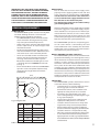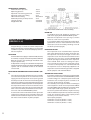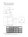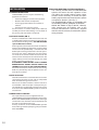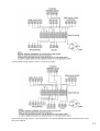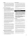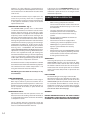
1
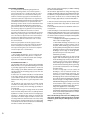
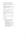
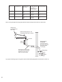
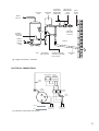
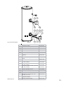
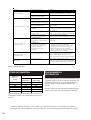
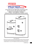
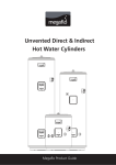
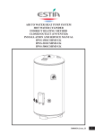
UNVENTED MAINS PRESSURE WATER HEATERS
120, 150, 170, 210, 250 and 300 LITRE CAPACITY INDIRECT MODELS
INSTALLATION AND SERVICING INSTRUCTIONS
PACK CONTENTS
The CENTERSTORE unvented cylinder water heater incorporating immersion heater(s) and thermal
controls l Factory fitted temperature/pressure relief valve l Cold water combination valve assembly
l Expansion vessel and mounting bracket l Tundish l Motorised valve l Compression nuts and olives
l Immersion heater spanner l Installation instructions
IMPORTANT: PLEASE READ AND UNDERSTAND THESE INSTRUCTIONS
BEFORE COMMENCING INSTALLATION. PLEASE LEAVE THIS MANUAL
WITH THE CUSTOMER FOR FUTURE REFERENCE.
THE BENCHMARK SCHEME
Benchmark places responsibilities on both manufacturers and installers. The purpose is to ensure that customers are provided with the correct equipment for their needs, that it is installed, commissioned and serviced in
accordance with the manufacturer’s instructions by competent persons and that it meets the requirements of
the appropriate Building Regulations. The Benchmark Checklist can be used to demonstrate compliance with
Building Regulations and should be provided to the customer for future reference.
Installers are required to carry out installation, commissioning and servicing work in accordance with the Benchmark Code of Practice which is available from the Heating and Hotwater Industry Council who manage and
promote the Scheme. Visit www.centralheating.co.uk for more information.
IMPORTANT NOTE TO USER: PLEASE REFER TO THE USER INSTRUCTIONS SECTION ON PAGES 13 AND 14 FOR IMPORTANT INFORMATION WITH RESPECT TO THE BENCHMARK SCHEME
INTRODUCTION
The CENTERSTORE cylinder is a purpose designed unvented water heater. The unit has a stainless steel inner
vessel, which ensures an excellent standard of corrosionresistance. The outer casing is a combination of resilient
thermoplastic mouldings and plastic coated corrosion
proofed steel sheet. All products are insulated with CFC
free polyurethane foam to give good heat loss
performance. ( See Table 6 )
The unit is supplied complete with all the necessary
safety and control devices needed to allow connection
to the cold water mains. All these components are preset
and not adjustable.
This appliance complies with the requirements of
the CE marking directive and is Kiwa approved to
show compliance with Building Regulations (Section G3).
The following instructions are offered as a guide to
installation which must be carried out by a competent plumbing and electrical installer in accordance
with Building Regulation G3, The Building Standards
(Scotland) Regulations 1990, or The Building Regulations (Northern Ireland).
NOTE: Prior to installation the unit should be stored
in an upright position in an area free from excessive
damp or humidity.
1
Contents
PAGE
INTRODUCTION.................................................................1
GENERAL REQUIREMENTS.............................................3
INSTALLATION-GENERAL...............................................4
INSTALLATION...................................................................10
COMMISSIONING.............................................................12
MAINTENANCE..................................................................12
USER INSTRUCTIONS.......................................................13
FAULT FINDING AND SERVICING.................................14
OTHER INFORMATION.....................................................16
ENVIRONMENTAL INFORMATION...............................16
COMMISSIONING CHECK LIST......................................17
SERVICE RECORD..............................................................18
GUARANTEE.......................................................................19
TECHNICAL SUPPORT AND SPARES...........................20
2
IMPORTANT: THIS APPLIANCE IS NOT INTENDED
FOR THE USE BY PERSONS (INCLUDING CHILDREN)
WITH REDUCED PHYSICAL, SENSORY OR MENTAL
CAPABILITIES, OR LACK OF KNOWLEDGE AND EXPERIENCE, UNLESS THEY HAVE BEEN GIVEN SUPERVISION OR INSTRUCTION CONCERNING THE USE OF
THE APPLIANCE BY A PERSON RESPONSIBLE FOR
THEIR SAFETY. CHILDREN MUST BE SUPERVISED.
GENERAL REQUIREMENTS
SITING THE UNIT
The CENTERSTORE cylinder must be vertically floor
mounted. Although location is not critical, the
following points should be considered:
• The CENTERSTORE cylinder should be sited to
ensure minimum dead leg distances, particularly to the point of most frequent use.
• Avoid siting where extreme cold temperatures
will be experienced. All exposed pipe work
should be insulated.
• The discharge pipework from the safety valves
must have minimum fall of 1:200 from the unit
and terminate in a safe and visible position.
• Access to associated controls and immersion
heaters must be available to provide for the
servicing and maintenance of the system.
Where these controls are installed against a wall
a minimum distance of 250mm must be left
(see Fig. 1).
• Ensure that the floor area for the CENTERSTORE
cylinder is level and capable of permanently
supporting the weight when full of water.
(see Table 1)
WALL
Min 250mm
Fig. 1: Siting the Unit
Type
Indirect
Capacity
(litres)
120
Weight of full
unit (kg)
147
150
181
170
204
210
257
250
300
300
360
Table 1: Unit weights
WATER SUPPLY
Bear in mind that the mains water supply to the
property will be supplying both the hot and cold
water requirements simultaneously. It is recommended that the maximum water demand is
assessed and the water supply checked to ensure
this demand can be satisfactorily met.
Note: A high mains water pressure will not always
guarantee high flow rates.
Wherever possible the mains supply pipe should be
22mm. We suggest the minimum supply requirements should be 1.5 bar pressure and 20 litres per
minute flowrate. However, at these values outlet
flow rates may be poor if several outlets are used
simultaneously.The higher the available pressure and
flow rate the better the system performance.
The CENTERSTORE cylinder has an operating pressure of 3.5 bar which is controlled by the cold
water combination valve assembly. The cold water
combination valve assembly can be connected to a
maximum mains pressure of 16 bar.
OUTLET/TERMINAL FITTINGS (TAPS, ETC.)
The CENTERSTORE cylinder can be used with most
types of terminal fittings. It is advantageous in many
mixer showers to have balanced hot and cold water
supplies. In these instances a balanced pressure
cold water connection should be placed between
the 2 pieces of the cold water combination valve
assembly (see Fig. 2). Outlets situated higher than
the CENTERSTORE cylinder will give outlet pressures
lower than that at the heater, a 10m height difference
will result in a 1 bar pressure reduction at the outlet.
All fittings, pipework and connections must have a
rated pressure of at least 6 bar at 80°C.
LIMITATIONS
The CENTERSTORE cylinder should not be used in
association with any of the following:
•
Solid fuel boilers or any other boiler in which
the energy input is not under effective
thermostatic control, unless additional and
appropriate safety measures are installed.
•
Ascending spray type bidets or any other
class 1 back syphonage risk requiring that a type
A air gap be employed.
•
Steam heating plants unless additional and
appropriate safety devices are installed.
•
Situations where maintenance is likely to be
neglected or safety devices tampered with.
•
Water supplies that have either inadequate
pressure or where the supply may be intermittent.
•
Situations where it is not possible to safely
pipe away any discharge from the safety valves.
• In areas where the water consistently contains a
high proportion of solids, e.g. suspended matter
that could block the strainer, unless adequate filtration
can be ensured.
3
OPERATIONAL SUMMARY
Maximum mains pressure
Operating pressure
Expansion vessel charge pressure
Expansion relief valve setting
T&P relief valve setting
Maximum primary circuit pressure
Storage capacity
Weight when full
16 bar
3.5 bar
3.5 bar
6 bar
90°C/10 bar
3 bar
See Table1
See Table1
Fig. 2: Cold water combination valve assembly
INSTALLATION – GENERAL
(SEE FIGS. 2 - 6)
PIPE FITTINGS
All pipe fittings are made via 22mm compression
fittings directly to the unit. The fittings are threaded
3/4”BSP male parallel should threaded pipe connections be required.
COLD FEED
A 22mm cold water supply is recommended, however,
if a 15mm (1/2”) supply exists, which provides sufficient
flow, this may be used (although more flow noise
may be experienced).
A stopcock or servicing valve should be incorporated
into the cold water supply to enable the CENTERSTORE
cylinder and its associated controls to be isolated
and serviced.
COLD WATER COMBINATION VALVE ASSEMBLY (FIG.
2)
The 2-piece cold water combination valve assembly
can be located anywhere on the cold water mains
supply prior to the expansion vessel (see Fig. 6) but
the two pieces do not have to be installed together.
The pressure reducing valve incorporates the pressure
reducer & strainer and the expansion valve incorporates
the expansion & check valves. Ensure that the valves
are installed in the correct order and orientation. No
other valves should be placed between the expansion valve and the CENTERSTORE cylinder.
A connection can be made between the expansion
and pressure reducing valves to provide a balanced
cold water connection. The expansion valve connection must not be used for any other purpose.
4
DRAIN TAP
A suitable draining tap should be installed in the
cold water supply to the CENTERSTORE cylinder
between the expansion valve (see Fig. 6) and the
heater at as low a level as possible.
It is recommended that the outlet point of the drain
pipework be at least 1 metre below the level of the
heater (this can be achieved by attaching a hose to
the drain tap outlet spigot).
EXPANSION VESSEL
The expansion vessel accommodates expansion
that results from heating the water inside the unit.
The expansion vessel is pre-charged at 3.5 bar. The
expansion vessel must be connected between the
expansion valve (see Fig. 2) and the CENTERSTORE
cylinder (see Fig. 6). The location of the expansion
vessel should allow access to recharge the pressure as and when necessary, this can be done using
a normal car foot pump. It is recommended that
the expansion vessel is adequately supported. An
expansion vessel wall mounting bracket is supplied
for this purpose and should be fitted.
SECONDARY CIRCULATION
If secondary circulation is required it is recommended
that it be connected to the CENTERSTORE cylinder
as shown in Fig. 3 via a swept tee joint into the cold
feed to the unit. A swept tee joint is available as an
accessory (order code no. 5133565).
The secondary return pipe should be in 15mm pipe
and incorporate a check valve to prevent backflow.
A suitable WRAS approved bronze circulation pump
will be required. On large systems, due to the
increase in system water content, it may be necessary
to fit an additional expansion vessel to the secondary
circuit. This should be done if the capacity of the
secondary circuit exceeds 10 litres.
Pipe capacity (copper):
15mm O.D. = 0.13 l/m (10 litres = 77m)
22mm O.D. = 0.38 l/m (10 litres = 26m)
28mm O.D. = 0.55 l/m (10 litres = 18m)
OUTLET
The hot water outlet is a 22mm compression fitting
located at the top of the cylinder. Hot water distribution pipework should be 22mm pipe with short runs
of 15mm pipe to terminal fittings such as sinks and
basins. Pipe sizes may vary due to system design.
Fig. 3: Secondary circulation connection
Fig. 4 General dimensions
NOMINAL
CAPACITY
(litres)
DIMENSIONS (mm)
A
B
C
D
COIL
RATING RECOVERY
(kW)
(mins)
HEATING TIME
DIRECT (mins)
120
315 364 615 906
12.5
23
110
150
315 364 800 1090
12.5
24
142
170
315 364 925 1216
16.0
25
163
210
250
315 364 1184 1474
16.0
29
205
315 364 1378 1731
18.0
30
252
300
315 364 1693 2045
19.0
35
304
Table 2: Dimensions and performance
Notes:
1. Recovery time based on heating 70% of capacity through 45°C.
2. Direct heating times assume use of lower element only, from cold, through 45°C.
5
DISCHARGE PIPEWORK
It is a requirement of Building Regulation G3
that any discharge from an unvented system is
conveyed to where it is visible, but will not cause
danger to persons in or about the building. The
tundish and discharge pipes should be fitted in
accordance with the requirements and guidance
notes of Building Regulation G3. The G3 Requirements
and Guidance section 3.9 are reproduced in the
following sections of this manual. Information Sheet
No. 33 available from the British Board of Agrément
gives further advice on discharge pipe installation.
For discharge pipe arrangements not covered by
G3 Guidance or BBA Info Sheet No.33 advice
should be sought from your local Building Control
Officer. Any discharge pipe connected to the pressure relief devices (Expansion Valve and Temperature/Pressure Relief Valve) must be installed in a
continuously downward direction and in a frost
free environment.
Water may drip from the discharge pipe of the
pressure relief device. This pipe must be left open
to the atmosphere. The pressure relief device is
to be operated regularly to remove lime deposits
and to verify that it is not blocked.
G3 REQUIREMENT
“...there shall be precautions...to ensure that the hot
water discharged from safety devices is safely conveyed to where it is visible but will not cause danger
to persons in or about the building.”
G3 GUIDANCE SECTION 3.9
The discharge pipe (D1) [see fig. 5 in this instruction
book] from the vessel up to and including the tundish
is generally supplied by the manufacturer of the hot
water storage system. Where otherwise, the installation
should include the discharge pipe(s) (D1) from the
safety device(s).
In either case the tundish should be vertical, located
in the same space as the unvented hot water storage
system and be fitted as close as possible and within
500mm of the safety device e.g. the temperature relief
valve.
The discharge pipe (D2) from the tundish should
terminate in a safe place where there is no risk to
persons in the vicinity of the discharge, preferably be
of metal and:
a. be at least one pipe size larger than the nominal
outlet size of the safety device unless its total equivalent
hydraulic resistance exceeds that of a straight pipe
9m long i.e. discharge pipes between 9m and 18m
equivalent resistance length should be at least two
sizes larger than the nominal outlet size of the safety
device, between 18 and 27m at least 3 sizes larger, and
so on. Bends must be taken into account in calculating
the flow resistance. Refer to Table 3,
6
Table 1 and the worked example [see Table 3 and Fig.
5 in this instruction book].
An alternative approach for sizing discharge pipes
would be to follow BS 6700:1987 Specification for design
installation, testing and maintenance of services supplying water for domestic use within buildings and
their curtilages, Appendix E, section E2 and table 21.
b. have a vertical section of pipe at least 300mm long,
below the tundish before any elbows or bends in the
pipework.
c. be installed with a continuous fall and in a frost free
environment.
d. have discharges visible at both the tundish and the
final point of discharge but where this is not possible or
is practically difficult there should be clear visibility at
one or other of these locations. Examples of acceptable
discharge arrangements are:
i. ideally below a fixed grating and above the
water seal in a trapped gully.
ii. downward discharges at low level; i.e. up
to 100mm above external surfaces such as
car parks, hard standings, grassed areas etc.
are acceptable providing that where children
may play or otherwise come into contact with
discharges a wire cage or similar guard is
positioned to prevent contact, whilst
maintaining visibility.
iii. discharges at high level; e.g. into a metal
hopper and metal down pipe with the end
of the discharge pipe clearly visible (tundish
visible or not) or onto a roof capable of
withstanding high temperature discharges
of water and 3m from any plastics guttering
system that would collect such discharges
(tundish visible).
iv. where a single pipe serves a number of
discharges, such as in blocks of flats, the
number served should be limited to not
more than 6 systems so that any installation
discharging can be traced reasonably easily.
The single common discharge pipe should be
at least one pipe size larger than the largest
individual discharge pipe (D2) to be connected.
If unvented hot water storage systems are
installed where discharges from safety devices
may not be apparent i.e. in dwellings
occupied by blind, infirm or disabled people,
consideration should be given to the installation
of an electronically operated device to warn
when discharge takes place.
Note: The discharge will consist of scalding water
and steam. Asphalt, roofing felt and non-metallic
rainwater goods may be damaged by such discharges.
Worked example of discharge pipe sizing
Fig. 5: shows a G1/2 temperature relief valve with a
discharge pipe (D2) having 4 No. elbows and length of
7m from the tundish to the point of discharge.
From Table 3:
Maximum resistance allowed for a straight length of
22mm copper discharge pipe (D2) from a G1/2
temperature relief valve is 9.0m.
Subtract the resistance for 4 No. 22mm elbows at 0.8m
each = 3.2m
Therefore the permitted length equates to: 5.8m
5.8m is less than the actual length of 7m therefore
calculate the next largest size.
Maximum resistance allowed for a straight length of
28mm pipe (D2) from a G1/2 temperature relief valves
equates to 18m.
Subtract the resistance of 4 No. 28mm elbows at 1.0m
each = 4.0m
Therefore the maximum permitted length equates to:
14m
As the actual length is 7m, a 28mm (D2) copper pipe
will be satisfactory.
WARNINGS:
• Under no circumstances should the factory
fitted temperature/pressure relief valve be
removed other than by a competent
person. To do so will invalidate any
guarantee or claim.
•
The cold water combination valve assembly
must be fitted on the mains water supply to
the CENTERSTORE cylinder.
•
No control or safety valves should be tampered
with or used for any other purpose.
•
The discharge pipe should not be blocked or
used for any other purpose.
•
The tundish should not be located adjacent
to any electrical components.
7
VALVE OUTLET
SIZE
MINIMUM SIZE OF
DISCHARGE PIPE D1
MINIMUM SIZE OF
DISCHARGE PIPE D2
FROM TUNDISH
MAXIMUM RESISTANCE
ALLOWED, EXPRESSED
AS A LENGTH OF
STRAIGHT PIPE (I.E. NO
ELBOWS OR BENDS
RESISTANCE CREATED BY
EACH ELBOW OR BEND
G 1/2
15MM
G 3/4
22MM
G1
28MM
22mm
28mm
35mm
28mm
35mm
42mm
35mm
42mm
54mm
UP TO 9M
UP TO 18M
UP TO 27M
UP TO 9M
UP TO 18M
UP TO 27M
UP TO 9M
UP TO 18M
UP TO 27M
0.8M
1.0M
1.4M
1.0M
1.4M
1.7M
1.4M
1.7M
2.3M
Table 3: Sizing of copper discharge pipe (D2) for common temperature relief valve outlet sizes
Safety device
(e.g. Temperature
relief valve)
Metal discharge pipe (D1) from
Temperature relief valve to tundish
500mm maximum
Tundish
300mm
minimum
Discharge pipe (D2) from tundish,
with continuous fall. See Building
Regulation G3 section 3.9d i-iv,
Table 4 and worked example
Discharge below
fixed grating
(Building Regulation
G3 section 3.9d gives
alternative points
of discharge)
Fixed grating
Trapped
gully
Fig. 5: Typical discharge pipe arrangement (extract from Building Regulation G3 Guidance section 3.9)
8
EXPANSION
VESSEL
T&P RELIEF
VALVE
BALANCED
COLD WATER
CONNECTION
(IF REQUIRED)
COLD WATER
COMBINATION
VALVE
(2-PIECE)
MAINS
WATER
SUPPLY
TO HOT
OUTLETS
ISOLATING
VALVE (NOT
SUPPLIED)
ELEMENT /
CONTROLS
HOUSING
PRIMARY
RETURN
TUNDISH
PRIMARY
FLOW
DRAIN COCK
(NOT SUPPLIED)
INLET
DISCHARGE
PIPE
SECONDARY RETURN
TAPPING (IF REQUIRED)
NOT SUPPLIED
Fig. 6: Typical installation - schematic
ELECTRICAL CONNECTIONS
INDIRECT THERMAL INDIRECT
THERMOSTAT
CUT-OUT
1
GREEN/
YELLOW
DIRECT
THERMOSTAT
2
1 2 3
1 2 3
TERMINAL
BLOCK
GREEN/
YELLOW
B
A
BROWN
BLUE
13 AMP MAINS
SUPPLY. 1.5mm 2
MIN. CABLE SIZE
TO INDIRECT SYSTEM
CONTROLS JUNCTION
BOX - SEE FIGS. 8/9
Fig. 7: Electrical connections (schematic)
9
INSTALLATION
PLUMBING CONNECTIONS
CENTERSTORE cylinders require the following
pipework connections.
• Cold water supply to and from inlet controls.
• Outlet to hot water draw off points.
• Discharge pipework from valve outlets to
tundish
• Connection to the primary circuit.
All connections are 22mm compression. However,
3/4”BSP parallel threaded fittings can be fitted to
the primary coil connections if required.
ELECTRICAL SUPPLY (FIG. 7)
All units are fitted with a 3kW immersion heater and
a combined thermostat and thermal cut-out to control the indirect heating source. The CENTERSTORE
cylinder MUST be earthed.
All wiring to the unit must be installed in accordance
with the latest IEE Wiring Regulations and the supply
circuits must be protected by a suitable fuse and
double pole isolating switch with a contact separation of at least 3mm in both poles. All connections
are made to the terminal block located under the
terminal cover mounted on the side of the unit. The
supply cable(s) must be routed through the cable
grip(s) in the terminal housing.
DISCONNECT FROM MAINS SUPPLY BEFORE
REMOVING ANY COVERS. DO NOT BYPASS THE
THERMAL CUT-OUTS IN ANY CIRCUMSTANCES.
Ensure the thermostat and thermal cut-out sensing
bulbs are pushed fully into the pockets on the element plate assembly.
BOILER SELECTION
The boiler should have a control thermostat and non
self-resetting thermal cut-out and be compatible
with unvented storage water heaters.
Where use of a boiler without a thermal cut-out is
unavoidable a “low head” open vented primary circuit should be used. The feed and expansion cistern
head above the CENTERSTORE cylinder should not
exceed 2.5m.
PRIMARY CIRCUIT CONTROL
The 2 port motorised valve supplied with the
CENTERSTORE cylinder MUST be fitted on the primary
flow to the CENTERSTORE cylinder heat exchanger
and wired in series with the indirect thermostat and
thermal cut-out fitted to the unit.
Primary circulation to the CENTERSTORE cylinder
heat exchanger must be pumped; gravity circulation
WILL NOT WORK.
10
SPACE AND HEATING SYSTEMS CONTROLS
The controls provided with the CENTERSTORE
cylinder will ensure the safe operation of the
unit within the central heating system. Other
controls will be necessary to control the space
heating requirements and times that the system
is required to function. (See Fig. 7)
The CENTERSTORE cylinder is compatible with
most heating controls, examples of electrical
circuits are shown in Figs. 8 and 9. However,
other systems may be suitable, refer to the
controls manufacturers’ instructions, supplied
with the controls selected, for alternative system
wiring schemes.
Fig. 8: Schematic wiring diagram - Basic 2 x 2 port valve system
Fig. 9: Schematic wiring diagram - 3 port mid position valve system. N.B. Must be used in conjunction with 2 port
zone valve supplied
11
COMMISSIONING
At the time of commissioning, please ensure all
relevant sections of the Benchmark Checklist,
located on Page 17 and 18 of this document, are
completed.
FILLING THE UNIT WITH WATER
• Check expansion vessel pre-charge pressure.
The vessel is supplied precharged to 3.5 bar to
match the control pressure of the pressure reducing valve.The precharge pressure is checked
using a car tyre gauge by unscrewing the plastic
cap opposite the water connection.
• Check all connections for tightness including
the immersion heater(s). An immersion heater
key spanner is supplied for this purpose.
• Ensure the drain cock is CLOSED.
• Open a hot tap furthest from the CENTERSTORE
cylinder.
• Open the mains stop cock to fill the unit.
When water flows from the tap, allow to run for
a few minutes to thoroughly flush through any
residue, dirt or swarf, then close the tap.
• Open successive hot taps to purge the system
of air.
SYSTEM CHECKS
• Check all water connections for leaks and
rectify as necessary.
• Turn off mains water supply.
• Remove the pressure reducing valve head
work to access the strainer mesh, clean
and re-fit.
• Manually open, for a few seconds, each
relief valve in turn, checking that water is
discharged and runs freely through the
tundish and out at the discharge point.
• Ensure that the valve(s) reseat
satisfactorily.
Fill the indirect (primary) circuit following the boiler
manufacturer’s commissioning instructions.To ensure
the CENTERSTORE cylinder primary heat exchanger
is filled, the 2 port motorised valve (supplied) should
be manually opened by moving the lever on the motor housing to the MANUAL setting. When the
primary circuit is full return the lever to the
AUTOMATIC position. Switch on the boiler, ensure
the programmer is set to Domestic Hot Water and
allow the CENTERSTORE cylinder to heat up to a
normal working temperature (60oC recommended,
approximately graduation 4 on the thermostat). If
necessary the temperature can be adjusted by
inserting a flat bladed screwdriver in the adjustment
knob (located on top of the thermostat mounting
bracket - see Fig.10) and rotating. The minimum
thermostat setting is 10°C.
12
The adjustment range 1 to 5 represents a temperature
range of 30o to 70oC. Check the operation of the
indirect thermostat and 2 port motorised valve and
that no water has issued from the expansion relief
valve or temperature/pressure relief valve during
the heating cycle.
THERMAL
CUT-OUT RESET BUTTON
THERMOSTAT
ADJUSTMENT
THERMAL
CUT-OUT
CABLE
CLAMPS
NOTE: THE HOUSING COVER AND
ELEMENT ASSEMBLY HAVE BEEN REMOVED
FROM THIS VIEW FOR CLARITY
TERMINAL BLOCK
THERMOSTAT
Fig. 10: Indirect thermostat and thermal cut-out
MAINTENANCE
MAINTENANCE REQUIREMENTS
Unvented hot water systems have a continuing
maintenance requirement in order to ensure safe
working and optimum performance. It is essential
that the relief valve(s) are periodically inspected and
manually opened to ensure no blockage has
occurred in the valves or discharge pipework.
Similarly cleaning of the strainer element and
replacement of the air in the expansion vessel will
help to prevent possible operational faults.
The maintenance checks described below should be
performed by a competent person on a regular basis,
e.g. annually to coincide with boiler maintenance.
After any maintenance, please complete the relevant
Service Interval Record section of the Benchmark
Checklist located on Page 17 and 18 of this document.
SAFETY VALVE OPERATION
Manually operate the temperature/pressure relief
valve for a few seconds. Check water is discharged
and that it flows freely through the tundish and
discharge pipework. Check valve reseats correctly
when released. NOTE: Water discharged may be
very hot!
Repeat the above procedure for the Expansion
Valve.
STRAINER
Turn off the cold water supply, boiler and immersion
heaters. The lowest hot water tap should then be
opened to de-pressurise the system. Remove the
pressure reducing cartridge to access the strainer
mesh. Wash any particulate matter from the strainer
under clean water. Re-assemble ensuring the seal
is correctly fitted. DO NOT use any other type of
sealant.
DESCALING IMMERSION HEATER(S)
Before removing the immersion heater(s) the unit
must be drained. Ensure the water, electrical supply and boiler are OFF before draining. Attach a
hosepipe to the drain cock having sufficient length
to take water to a suitable discharge point below the
level of the unit. Open a hot tap close to the unit
and open drain cock to drain unit.
Open the cover(s) to the immersion heater housing(s)
and disconnect wiring from immersion heater(s)
thermostat(s). Remove thermostat by carefully pulling
outwards. Remove thermostat capillary sensors from
the pockets on the immersion heater. Unscrew
immersion heater backnut(s) and remove immersion
heater from the unit. A key spanner is supplied with
the CENTERSTORE cylinder unit for easy removal/
tightening of the immersion heater(s). Over time
the immersion heater gasket may become stuck to
the mating surface. To break the seal insert a round
bladed screwdriver into one of the pockets on the
immersion heater and gently lever up and down.
Carefully remove any scale from the surface of the
element(s). DO NOT use a sharp implement as
damage to the element surface could be caused.
Ensure sealing surfaces are clean and seals are
undamaged, if in doubt fit a new gasket
(part number 95 611 822).
Replace immersion heater(s) ensuring the lower
(right angled) element hangs vertically downwards
towards the base of the unit. It may be helpful to
support the immersion heater using a round bladed
screwdriver inserted into one of the thermostat
pockets whilst the backnut is tightened. Replace
thermostat capillaries into pocket. Replace the immersion heater thermostat by carefully plugging
the two male spade terminations on the underside
of the thermostat head into the corresponding terminations on the element. Rewire, check, close and
secure immersion heater housing cover(s).
EXPANSION VESSEL CHARGE PRESSURE
Remove the dust cap on top of the vessel. Check the
charge pressure using a tyre pressure gauge. The
pressure (with system de-pressurised) should be 3.5 bar.
If it is lower than the required setting it should be
re-charged using a tyre pump (Schrader valve type).
DO NOT OVER-CHARGE. Re-check the pressure and
when correct replace the dust cap.
RE-COMMISSIONING
Check all electrical and plumbing connections are
secure. Close the drain cock. With a hot tap open,
turn on the cold water supply and allow unit to
refill. DO NOT switch on the immersion heater(s) or
boiler until the unit is full. When water flows from
the hot tap allow to flow for a short while to purge
air and flush through any disturbed particles. Close
hot tap and then open successive hot taps in system
to purge any air.
When completely full and purged check system for
leaks. The heating source (immersion heater(s) or
boiler) can then be switched on.
USER INSTRUCTIONS
WARNINGS
IF WATER ISSUES FROM THE TEMPERATURE/
PRESSURE RELIEF VALVE ON THE CENTERSTORE
CYLINDER SHUT DOWN THE BOILER. DO NOT
TURN OFF ANY WATER SUPPLY. CONTACT A
COMPETENT INSTALLER FOR UNVENTED WATER
HEATERS TO CHECK THE SYSTEM.
DO NOT TAMPER WITH ANY OF THE SAFETY
VALVES FITTED TO THE CENTERSTORE SYSTEM.
IF A FAULT IS SUSPECTED CONTACT A
COMPETENT INSTALLER.
BENCHMARK
CENTERSTORE, is a licensed member of the
Benchmark Scheme which aims to improve the
standards of installation and commissioning of
domestic heating and hot water systems in the UK
and to encourage regular servicing to optimise
safety, efficiency and performance.
Benchmark is managed and promoted by the
Heating and Hotwater Industry Council. For more
information visit www.centralheating.co.uk.
Please ensure that the installer has fully completed
the Benchmark Checklist on Page 17 and 18 of this
manual and that you have signed it to say that you
have received a full and clear explanation of its operation. The installer is legally required to complete a
commissioning checklist as a means of complying
with the appropriate Building Regulations (England
and Wales).
All installations must be notified to Local Area
Building Control either directly or through a
Competent Persons Scheme. A Building Regulations
Compliance Certificate will then be issued to the
customer who should, on receipt, write the
Notification Number on the Benchmark Checklist.
This product should be serviced regularly to
13
optimise its safety, efficiency and performance.
The service engineer should complete the relevant
Service Record on the Benchmark Checklist after
each service.
The Benchmark Checklist may be required in the
event of any warranty work and as supporting
documentation relating to home improvements
in the optional documents section of the Home
Improvements Pack.
TEMPERATURE CONTROLS (Fig. 7)
The CENTERSTORE cylinder units are fitted with
an indirect thermostat and thermal cut-out. These
controls must be wired in series with the 2 port
motorised zone valve supplied to interrupt the flow
of primary water around the heat exchanger coil
when the control temperature has been reached.
The controls are located within the lower terminal
housing along with the immersion heater thermostat.
The thermostat is factory set to give a water storage
temperature of approx. 55o to 60oC. Access to the
thermostat can be made by opening the terminal
housing cover - DISCONNECT THE ELECTRICAL
SUPPLY BEFORE OPENING THE COVER. Temperature
adjustment is made by inserting a flat bladed screwdriver in the adjustment knob and rotating. The
minimum thermostat setting is 10oC.The adjustment
range 1 to 5 represents a temperature range of 30o
to 70oC (60oC will be approximately position 4). If in
any doubt contact a competent electrician.
An immersion heater is also provided for use should
the indirect heat source be shut down for any purpose.
The immersion heater control temperature is set
using the immersion heater thermostat.
DO NOT bypass the thermal cut-out(s) in any
circumstances.
FLOW PERFORMANCE
When initially opening hot outlets a small surge in
flow may be noticed as pressures stabilise. This is
quite normal with unvented systems. In some areas
cloudiness may be noticed in the hot water. This is
due to aeration of the water, is quite normal and
will quickly clear.
OPERATIONAL FAULTS
Operational faults and their possible causes are
detailed in the Fault Finding section of this book. It
is recommended that faults should be checked by
a competent installer.
The air volume within the expansion vessel will
periodically require recharging to ensure expanded
water is accommodated within the unit.
14
A discharge of water INTERMITTENTLY from the
expansion valve will indicate the air volume has
reduced to a point where it can no longer accommodate the expansion.
FAULT FINDING & SERVICING
IMPORTANT
• After servicing, complete the relevant
Service Interval Record section of the Benchmark Checklist located on page 17 and 18 of
this document.
• Servicing should only be carried out by
competent persons in the installation and
maintenance of unvented water heating
systems.
• Any spare parts used MUST be authorised
CENTERSTORE parts.
• Disconnect the electrical supply before
removing any electrical equipment covers.
• NEVER bypass any thermal controls or
operate system without the necessary
safety valves.
• Water contained in the CENTERSTORE cylinder
may be very hot, especially following a thermal
control failure. Caution must be taken when
drawing water from the unit.
SPARE PARTS
A full range of spare parts are available for the
CENTERSTORE cylinder range (See Table 4). Refer
to the technical data label on the unit to identify
the model installed and ensure the correct part is
ordered. You will need to quote the serial number
and the guarantee code, which are printed on the
data label.
FAULT FINDING
The fault finding chart on page 16 will enable
operational faults to be identified and their possible causes rectified. Any work carried out on the
CENTERSTORE cylinder unvented water heater and
its associated controls MUST be carried out by a
competent installer for unvented water heating
systems. In case of doubt contact service support
(see contact details on back page).
WARNING
DO NOT TAMPER WITH ANY OF THE SAFETY VALVES
OR CONTROLS SUPPLIED WITH THE CENTERSTORE
CYLINDER AS THIS WILL INVALIDATE ANY GUARANTEE
3
11
18
22
2
19
16
15
18
1
3
20
Fig. 11: Spares Diagram
1
D e s c r ip t io n
Imme r s io n h e a t e r
P a r t No .
95 606 961
2
3
4
5
6
7
Imme r s io n
Imme r s io n
Imme r s io n
T u n d is h
E x p a n s io n
E x p a n s io n
95
95
95
95
95
95
8
C o ld w a t e r c o mb in a t io n v a lv e
c o mp le t e
95 605 047
9
C o ld w a t e r c o mb in a t io n v a lv e b o d y
95 605 048
P r e s s u r e r e d u c in g v a lv e c a r t r id g e
3.5bar
T e mp e r a t u r e /P r e s s u r e R e lie f V a lv e
95 607 029
95 605 810
12
E x p a n s io n v e s s e l 1 2 lit r e (1 2 0 a n d
1 5 0 lit r e mo d e ls )
95 607 863
13
E x p a n s io n v e s s e l 1 8 lit r e (1 7 0 a n d
2 1 0 lit r e mo d e ls )
95 607 864
14
E x p a n s io n v e s s e l 2 4 lit r e (2 5 0 a n d
3 0 0 lit r e mo d e ls )
10
11
15
16
17
18
19
20
21
22
Table 4: Spares
h e a t e r g a s ke t
h e a t e r b a c kn u t
h e a t e r ke y s p a n n e r
v a lv e c a r t r id g e - 6 b a r
v a lv e c o mp le t e - 6 b a r
In d ir e c t t h e r mo s t a t
In d ir e c t t h e r ma l c u t -o u t
M o t o r is e d v a lv e 2 p o r t
T e r min a l cover
4 W a y t e r min a l b lo c k
Combined thermostat and
thermal cut out
A c c e s s o r y kit (in d ir e c t a n d w it h o u t
e x p a n s io n v e s s e l)
Blanking Plate Assembly
611
607
607
605
605
607
822
869
861
838
864
030
95 607 612
95
95
95
95
95
95
612
612
605
614
607
612
697
698
049
094
902
026
95 607 968
95 607 064
15
FAUL T
P O S S IB L E C A U S E
1. M a in s s u pp ly o ff.
R E M E DY
1 . C h ec k and op en s top c oc k .
2 . Turn o ff w a ter s u pp ly . R em ove s tra in er
a nd c le an (s ee M ainten an c e s ec tion ).
3 . C h ec k and refit as re qu ired .
2. S tra in er bloc k e d.
N o ho t w ate r flow
3. C old W ater C om bination
V alve inc orrec tly fitted .
1. B A C K U P im m e rs ion h ea te r
1 . C h ec k and s w itc h o n.
no t s w itc hed on.
2. B A C K U P im m e rs ion h ea te r
2 . C h ec k . R e s e t b y pu s h in g bu tto n.
the rm al c ut-ou t h as ope rated .
W a ter from hot tap s is c o ld
W a ter dis c harg es from
E x pa ns io n V alve
W a ter dis c harg es from
T& P R e lief V alve
3. IN D IR E C T prog ram m e r s et
to C en tra l H ea tin g on ly .
3 . C h ec k . S e t to a D o m e s tic H ot W a te r
p ro gra m m e.
4. IN D IR E C T boiler no t
w ork ing .
4 . C h ec k boiler op eration . If fau lt is
s us pec ted c on s ult bo iler m an ufac turer's
ins tru c tions .
5. IN D IR E C T th erm a l c ut-ou t
ha s op era te d.
5 . C h ec k . R e s e t b y pu s h in g bu tto n on c u to ut. C h ec k op eration of ind ire c t therm o s ta t.
6. IN D IR E C T m oto ris e d va lve
no t c on ne c ted c orrec tly .
1. IN TE R M ITTE N TL Y
E x p ans io n V es s e l c harg e
pre s s u re ha s red uc ed b elow
3.5 bar.
2. C O N TIN U A L LY
a. C old W ater C om bination
V alve P res s ure R e du c er n ot
w ork ing c o rre c tly .
b. E x p an s ion V alve s ea t
da m ag ed .
6 . C h ec k w iring a nd/o r p lu m bin g
c on nec tio ns to m otoris e d valve (s e e F ig . 7 ).
1. Th erm a l c ontro l failu re
N O TE w ater w ill b e ve ry ho t.
1. O x y ge na te d w ate r.
M ilk y w ater
1 . S e e M ainte na nc e s e c tio n for re-c h arging
p ro c e du re .
2 a. C hec k pre s s ure from C old W ater
C om bina tion V alve. If grea ter than 3.5b ar
rep lac e P re s s ure R ed uc er c artridge .
2 b. R em o ve E x p ans io n V alve c artrid ge .
C he c k c on ditio n of s e at. If nec es s a ry fit
n ew E x pa ns io n V alve c artridg e.
1 . S w itc h off pow e r to im m e rs ion h ea te r(s )
a nd s hu t d ow n b oile r. D O N O T turn o ff
w ate r s up ply . W h en d is c h arge s top s
c he c k a ll th erm a l c on tro ls , rep lac e if fa ulty .
1 . W ate r from a p res s uris e d s y s tem
rele as e s ox y g en b ub bles w h en flow in g. Th e
m ilk ine s s w ill dis a ppe ar after a s hort w hile .
Table 5: Fault finding chart
OTHER INFORMATION
Nominal
Capacity
(litres)
120
150
170
210
250
300
Standing Heat Loss
per day
(kW h/24h)
1.47
1.70
1.92
2.10
2.22
2.52
per year
(kW h/365d)
537
621
701
767
811
920
ENVIRONMENTAL
INFORMATION
CENTERSTORE products are manufactured from many
recyclable materials. At the end of their useful life they
should be disposed of at a Local Authority Recycling
Centre in order to realise the full environmental
benefits.
Insulation is by means of an approved CFC/HCFC free polyurethane foam with an ozone depletion factor of zero.
Table 6: Standing heat losses (based on an ambient air
temperature of 20oC and a stored water temperature
of 65oC)
While the following Checklist can be used for any installation covered by its description, only appliances
manufactured by Scheme Members will be covered by the rules and requirements of the Benchmark Scheme.
16
17
18
GUARANTEE
The CENTERSTORE stainless steel vessel carries a full 25 year parts guarantee against
faulty manufacture or materials provided that:
• It has been correctly installed as per the instructions contained in the instruction manual
and all relevant Codes of Practice and Regulations in force at the time of installation.
• The Benchmark Checklist has been completed upon commissioning and the Benchmark
Service Record is completed for each service.
• It has not been modified in any way, other than by CENTERSTORE.
• It has not been frost damaged.
• It has only been used for the storage of potable water.
• It has not been tampered with or been subjected to misuse or neglect.
• The damage is not scale related.
• Within 60 days of installation the user completes and returns the certificate supplied
along with the proof of purchase to register the product.
• It has been installed in the United Kingdom.
The expansion vessel is guaranteed for a period of 2 years from the date of purchase. The
CENTERSTORE components, immersion heater and thermal controls are guaranteed for
a period of 2 years from the date of purchase. Evidence of purchase and date of supply
may be required. The unit is not guaranteed against damage due to frost. The guarantee
is transferable. This guarantee does not affect your statutory rights.
19
TECHNICAL SUPPORT & SPARES
For all technical support, replacement parts and service issues please
contact:
CENTERSTORE
Brooks House,
Coventry Road,
Warwick,
CV34 4LL
Tel: 0844 871 1532
The policy of CENTERSTORE is one of continuous product development and, as such, we reserve the right to
change specifications and guarantee terms and conditions without notice.
20
36006051 issue 3