1
SNMP-32 Series
(Web-based monitoring SNMP card)
User’s Manual
34000241 Rev1
Table of Contents
Notice....................................................................................................................................................... 3
1.
Introduction ...................................................................................................................................... 4
1-1. Features ................................................................................................................................... 4
1-2. Package Contents .................................................................................................................... 5
1-3. Applications.............................................................................................................................. 6
2.
Installation Procedure...................................................................................................................... 7
3.
Setup Procedure............................................................................................................................... 8
4.
Web Management Interface.............................................................................................................. 10
4-1. Main Menu ............................................................................................................................... 10
4-2. Information: System Status...................................................................................................... 11
4-3. Configuration: Network ............................................................................................................ 11
4-4. Configuration: SNMP............................................................................................................... 12
4-5. Configuration: Email ................................................................................................................ 14
4-6. Configuration: PPP.................................................................................................................. 15
4-7. Configuration: Web/Telnet....................................................................................................... 15
4-8. Configuration: System Time .................................................................................................... 16
4-9. Log Information: Event ............................................................................................................ 16
4-10. Log Information: Data .............................................................................................................. 18
5.
Firmware Upgrade Procedure.......................................................................................................... 19
6.
Telnet ................................................................................................................................................ 21
6-1. Telnet Configuration ................................................................................................................. 21
7.
Connected Device ............................................................................................................................ 23
7-1. Uninterruptible Power Supply (UPS) ......................................................................................... 23
7-2. Remote Power Manager (RPM) ................................................................................................ 29
7-3. Current Probe Sensor (CPS) .................................................................................................... 32
7-4. Temp/Hum32-Probe (ENV)....................................................................................................... 33
7-5. Automatic Transfer Switch (ATS).............................................................................................. 34
8.
Configuring the NMS........................................................................................................................ 35
9.
Appendix........................................................................................................................................... 36
10. Troubleshooting............................................................................................................................... 38
11. Obtaining Technical Assistance...................................................................................................... 39
12. Limited Product Warranty ................................................................................................................ 40
2
Notice
This equipment has been tested and found to comply with the limits for a “Class A” digital device, pursuant to Part 15 of
the FCC rules. These limits are designed to provide reasonable protection against harmful interference when the
equipment is operated in a commercial environment. This equipment generates, uses and can radiate radio frequency
energy and if not installed and used in accordance with the instruction manual, may cause interference to radio
communications. Operation of this equipment in a residential area is likely to cause harmful interference, in which case
the user will be required to correct the interference at the user’s own expense.
This digital apparatus does not exceed the “Class A” limits for radio noise emissions from digital apparatus set out in the
Radio interference regulations of the Canadian Department of Communications.
Trademarks
MINUTEMAN is a registered trademark of Para Systems, Inc. All other trademarks are the property of their respective
holders.
Conventions used in this guide
This guide uses these conventions:
Bold italic print, as shown in this example, indicates field names, menu items, or values in the SNMP-32 Card software
agent.
Bold print, as shown in this example, indicates filenames, directories, or items that you must type exactly as they
appear.
Italic print words or letters in braces { } indicate values that you must supply. For example: {drive}:\setup
Italic print words or letters in brackets < > indicate keys to press. If two keys are separated by a + plus symbol, then the
first key should be pressed and held down while pressing the second key. For example: <alt+enter>.
Note: Notes contrast from the text to emphasize their importance.
Warning:
These messages alert you to specific procedures or practices; serious consequences may result
including injury if you disregard them.
Copyright 2004
Para Systems, Inc.
Unauthorized reproduction prohibited.
3
1. Introduction
A UPS can be configured with either an internal or an external SNMP-32 card; this SNMP-32 card is then connected to
the network. The SNMP-32 card contains a MIB agent. The agent communicates both solicited and unsolicited
messages to the Network Management Station (NMS). Unsolicited messages are defined by the MIB and are built into
the agent for critical items such as AC power failure and low battery detection. The agent recognizes these critical
events and immediately forwards them to the Network Management Station. The network manager will immediately
notice the alarm and the flashing icon of the SNMP-32 card. By clicking on the icon, you will be able to see the alarm
messages. If nobody is present, the Network Management Station will shutdown the programs, the OS server and
eventually the UPS safely.
1-1. Features
The SNMP-32 card connects directly to your UPS. It runs an embedded Simple Network Management Protocol (SNMP)
software agent. This agent responds to SNMP GETS and SETS and also forwards traps to designated recipients when
critical conditions occur within the UPS, such as the UPS going on battery backup mode during a power failure.
The SNMP-32 card features:
• Internet ready — It supports TCP/IP, UDP, SNMP, Telnet, SNTP, PPP, HTTP and SMTP protocols. The user can
use a SNMP manager or a Web browser to monitor the UPS through a network.
• Multiple OS support — As long as there is Network Management software present.
• Remote setup support — Once an IP address is assigned the rest can be setup remotely through Telnet or a
Browser.
• Remote monitoring — Monitors the status of one UPS from a remote workstation (Web browser or NMS).
• Remote Control — Turns the UPS off (or a battery test) when the NMS sends the proper command.
• NMS To Receive UPS Alarms — These traps (unsolicited messages) inform the user about the power condition of
the connected UPS.
• Works with most major NMS on Ethernet — SNMP-32 card works with the most widely used Network
Management Systems: HP Open View, Sun NetManager, IBM NetView, and many more.
• Remote Software upgrade — The SNMP-32 card supports Software upgrade through the Ethernet remotely.
• Daily historical reports — Automatically emails daily history reports to the specified users.
• Auto-Sense — Auto-Senses 10/100M Ethernet.
• Event Notifications — Sends both SNMP Traps and Emails for event notification.
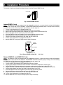
• 3-Ports — Environmental Monitoring (Optional Kit), External Modem, and Ethernet.
Fig. 1-SNMP-32L Card
ENV port — The connection for a Temperature/Humidity Probe
Modem port — The connection for an External Modem
Reset Button — The Reset Button is used to reset the SNMP-32 card
Status LEDs — See the Status LED Table below
Ethernet port — The connection for the LAN
LAN Port LEDs — See the LAN Port LED Table below
4
Fig. 2-SNMP-32S Card
Ethernet port — The connection for the LAN
LAN Port LEDs — See the LAN Port LED Table below
Modem port — The connection for an External Modem
ENV port — The connection for a Temperature/Humidity Probe
Status LEDs — See the LED Table below
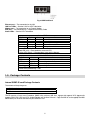
Status LED Table
Yellow
Red
Green
Status
OFF
OFF
Solid ON Power ON
Flashing
Solid ON Solid ON System initial
Solid ON
OFF
Solid ON Normal operation
Solid ON
Flashing
Solid ON No connection to UPS
Flashing
Flashing
Solid ON Writing data to flash memory
Green LED (PWR): Power state
Red LED (Link): Correspondence state with UPS
Yellow LED (Action): Correspondence state with the Network
LAN Port LED Table
Yellow
Green
Status
OFF
Solid ON
Network Connectivity speed is 100M
OFF
Flashing
Transmitting data
Solid ON
OFF
Connectivity speed is 10M
Flashing
OFF
Transmitting data
Green LED (Connectivity): 100M
Yellow LED (Connectivity): 10M
1-2. Package Contents
Internal SNMP-32 card Package Contents
The contents of the package are:
U
U
U
SNMP-32 Card
RJ11 to RS232 Serial Cable (SNMP-32S) for external modem only
CD
The CD contains a Quick Install Procedure, SNMP Utility software, MIB files: dgpups.mib supports UPS, dgprpm.mib
supports RPM, ENV, CPS and ATS, Acrobat Reader and the User’s Manual. Copy the MIB file to the appropriate NMS
MIB directory for the UPS connected to your SNMP-32 card.
5
External SNMP-32 card Package Contents (SNMP-32L Only)
The external adaptor is used to connect the SNMP-32L card to the UPS, when the UPS does not have an option slot.
The contents of the package are:
U
U
U
U
U
External Adaptor Box
Power Adaptor
DB9 Male-to-Female Serial Cable
SNMP-32 Card
CD
1-3. Applications
SNMP-32 card and the UPS
A UPS can be configured with either an internal or an external SNMP-32 card; then it is connected to the network. The
SNMP-32 card contains a MIB agent. The agent communicates both solicited and unsolicited messages to the Network
Management Station (NMS). Unsolicited messages are defined by the MIB and are built into the agent for critical items
such as AC power failure and low battery detection. The agent recognizes these critical events and immediately
forwards them to the Network Management Station. The network manager will immediately notice the alarm and the
flashing icon of the SNMP-32 card. By clicking on the icon, you will be able to see the alarm messages. If nobody is
present, the Network Management Station will shutdown the programs, the OS server and eventually the UPS safely.
SNMP-32 card and the RPM (Remote Power Manager)
When the RPM is connected to the network with the SNMP-32L card, the system manager could check each device’s
condition via a Web Browser. The manager could monitor and control the devices by simply inputting the IP address of
the SNMP-32L card. When there is an abnormal power condition the SNMP-32L card will send the trap information to
the system manager, and then the system manager can take the appropriate action.
SNMP-32 card and the ATS (Automatic Transfer Switch)
An ATS can be configured with the SNMP-32 card; then it is connected to the network. The ATS is an Automatic
Transfer Switch with redundant input sources. The ATS can be viewed and controlled via a Web Browser.
SNMP-32 card and the CPS (Current Probe Sensor)
The CPS and the SNMP-32 card can be used to monitor the current (Amps) of 16 devices. The information can be view
via a Web Browser.
SNMP-32 card and the ENV (Environmental Monitoring)
A Temperature/Humidity Probe can be connected to the SNMP-32 card to monitor the temperature and humidity of the
surrounding environment. The SNMP-32 card is then, connected to the network to view the environmental conditions via
a Web Browser. When an abnormal condition occurs, a trap can be sent to the system manager and activated some preset action configured by administrator.
6
2. Installation Procedure
This section will guide you through installing the Internal and the External SNMP-32 card.
UPS
Internal SNMP
Fig. 3-Internal SNMP-32 Card
Internal SNMP-32 card
NOTE: The SNMP-32 cards are designed to be Hot Swappable, but there is a remote chance that when Hot-Swapping
the SNMP-32 card that the UPS will shutdown. MINUTEMAN recommends following steps 1 through 9 when installing
the SNMP-32 card, but to hot-swap, skip to step number 3 and omit steps 7, 8.
1. Turn off all the equipment that is plugged into the UPS.
2. Turn off the UPS and unplug the UPS’s power cord from the AC wall outlet.
3. Remove the two retaining screws from the option slots cover plate (rear panel of the UPS).
4. Remove the option slot’s cover plate (rear panel of the UPS).
5. Insert the SNMP-32 card into the option slot and re-install the two retaining screws.
6. Connect the Ethernet cable to the Ethernet Port on the SNMP-32 card.
7. Plug the UPS’s power cord into the AC wall outlet and turn the UPS on.
8. Turn on all the equipment that is plugged into the UPS.
9. Now the SNMP-32 is ready to be Setup (see the Setup Procedure).
UPS
Power
Adapter
External SNMP
Serial UPS cable
Fig. 4-External SNMP-32 Card (SNMP-32L Only)
External SNMP-32 card (SNMP-32L Only)
NOTE: The SNMP-32 cards are designed to be Hot Swappable, but there is a remote chance that when Hot-Swapping
the SNMP-32 card that the UPS will shutdown. MINUTEMAN recommends following steps 1 through 11 when installing
the SNMP-32 card, but to hot-swap, skip to step number 3 and omit steps 9, 10.
1. Turn off all the equipment that is plugged into the UPS.
2. Turn off the UPS and unplug the UPS’s power cord from the AC outlet.
3. Plug the power adaptor’s connector into the connector on the external adaptor box, labeled “Input”.
4. Plug the DB9 Male to Female cable into the connector on the external adaptor box, labeled “To UPS”.
5. Plug the other end of the DB9 Male to Female cable into the Serial Port on the UPS (rear panel of the UPS).
6. Plug the power adaptor into one of the Battery Powered outlets of the UPS.
7. Insert the SNMP-32 card into the option slot and install the two retaining screws.
8. Connect the Ethernet cable to the Ethernet Port on the SNMP-32 card.
9. Plug the UPS’s power cord into the AC wall outlet and turn the UPS on.
10. Turn on all the equipment that is plugged into the UPS.
11. Now the SNMP-32 card is ready to be setup (see the Setup Procedure).
7
3.
Setup-Procedure
This section will guide you through the Setup-Procedure of the SNMP-32 Card.
NOTE: The minimum requirement to operate the SNMP-32 Card is to setup the IP Address. The SNMP Utility
supports most Windows Operating Systems (98, 2000, XP).
1. Load the SNMP Utility CD into the CD-ROM drive, and then open the ‘Install SNMP Utility’.
2. Once the installation is complete, there will be a ‘SNMP Utility’ group in the Windows ’Start’
3. Click the “SNMP Utility” to initiate the SNMP Utility program (Fig. 5).
Æ ‘Program Group’.
Fig. 5-SNMP Utility Group
4. Once the SNMP Utility is open, the SNMP Utility will search for the network adapter automatically, or, click on
Network Selection from the main page. The screen will display the network adapter that was located. Click on
the network adapter, and then press “OK” to return to the main page of SNMP Utility (Fig. 6).
Fig. 6-SNMP Utility: Network Selection
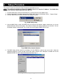
5. The SNMP Utility will then search for and display all of the SNMP-32 cards that are on your LAN. Select the
appropriate SNMP-32 card on the right side of the screen, and then click “Configure” or double click on the
appropriate SNMP-32 card to open the Configuration Menu (Fig. 7).
Fig. 7-SNMP Utility: Configuration Menu
8
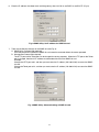
6. Enter the IP address; the subnet mask and the gateway, then click OK or use DHCP or use BOOTP (Fig. 8).
Fig. 8-SNMP Utility: Set IP address for SNMP-32 card
7. There are two Security features for the SNMP-32 card (Fig. 9):
A. SNMP Utility Password (Not required):
Once the password is entered, the SNMP-32 card cannot be accessed without the correct password.
B. Management Protocol (Not required):
The HTTP port and the Telnet port can be changed for security purposes. When the HTTP port or the Telnet
port is changed, then the full IP address must be entered to access the SNMP-32 card.
Example:
Change the HTTP port to 81, and then you must enter the IP address (192.168.0.5:81) to access the SNMP32 card.
Change the Telnet port to 24, and then you must enter the IP address (192.168.0.5:24) to access the SNMP32 card.
Fig. 9-SNMP Utility: Advanced setting of SNMP-32 card
9
4. Web Management Interface
Once the SNMP-32 card installation and set-up procedure is complete, you are now able to monitor and control the
SNMP-32 card via a Web Browser.
1. Open a Web Brower (Netscape, Internet Explore, Opera, Mozilla).
2. Enter the SNMP-32 card’s IP Address.
3. Enter the User Name and the Password (Not required). If a User Name or a Password was not entered in the
Set-Up Procedure, then click OK (Fig. 10).
NOTE: There is no default User Name or Password.
Fig. 10-SNMP-32 card: Login Screen
4-1. Main Menu
On the left hand-side of the Main Menu, there are four categories (Fig. 11):
1. Information:
Provides the information about the connected Device.
2.
Configuration:
Configure the network and devices setting.
3.
Log Information:
Record the events and data that is generated by device.
4.
Device selection:
Select the device to monitor and control, including the UPS, RPM, CPS, ENV
and ATS.
Fig. 11-Main Menu Screen
10
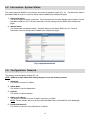
4-2. Information: System Status
This screen shows the SNMP-32 card’s System Information and Network setting (Fig. 12). The information shown is
provided by SNMP-32 card or it is the user settings from the SNMP Utility Configuration pages.
1. System Information:
This section shows the System Information. The Firmware Version, the Serial Number and the System Time are
provided by SNMP-32 card. The other information is the user settings from the SNMP Utility Configuration
pages.
2. Network Status:
This section shows the Network settings. The MAC address is provided by SNMP-32 card. The other
information is the user settings from the SNMP Utility Configuration pages.
Fig. 12-System Status Screen
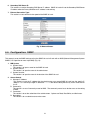
4-3. Configuration: Network
This screen is to set the Network settings (Fig. 13).
NOTE: SNMP-32 card will reboot after making changes to any of the following sections.
1. IP Address:
This section is to set the IP address.
2. Subnet Mask:
This section is to set the Subnet Mask.
3. Gateway:
This section is to set the Gateway.
4. Obtain an IP address:
This section is to choose to set the IP address manually or via DHCP.
NOTE: The four sections above can be set in either the SNMP Utility or the SNMP-32 card’s Web pages.
5. Primary DNS Server IP:
This section is to set the Primary DNS Server IP address.
11
6. Secondary DNS Server IP:
This section is to set the Secondary DNS Server IP address. SNMP-32 card will use the Secondary DNS Server
IP address when the Primary DNS Server IP address is not working.
7. Ethernet Connection Type:
This section is to set communication speed of the SNMP-32 card.
Fig. 13-Network Screen
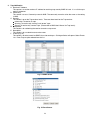
4-4. Configuration: SNMP
This screen is to set the SNMP settings so that the SNMP-32 card will work with an NMS (Network Management System:
SNMPC, HP OpenView or most major NMS) (Fig. 14).
1. MIB System
A. System Name:
This section is to input a name for the SNMP-32 card.
B. System Contact:
This section is to input the name of the administrator.
C. System Location:
This section is to input the name of the location of the SNMP-32 card.
2. Access Control
A. Manager IP Address:
This section is to set the IP address that the administrator can manage SNMP-32 card from the specific IP
address. It is valid for up to eight IP addresses. *.*.*.* is the default setting without any access restriction for
the IP.
B. Community:
This section is to set a Community name for NMS. The community name has to be the same as the setting
in NMS.
C. Permission:
This section is to set the authorities of the administrators. Options are Read, Read/Write, and No Access.
D. Description:
This section is for an administrator to make notes.
12
3. Trap Notification
A. Receiver IP Address:
This section is to set the receivers IP address for receiving traps sent by SNMP-32 card. It is valid for up to
eight IP Addresses.
B. Community:
This section is to set a Community name for NMS. The community name has to be the same as the setting
in NMS.
C. Severity:
This section is to set the Trap receiver levels. There are three levels for the Trap receiver:
z Information: To receive all traps.
z Warning: To receive only “warning” and “severe” traps.
z Severe: To receive only “severe” traps. (Please refer to NMS User’s Manual for Trap levels).
D. Acceptance:
This section is for authorizing the receiver to receive a trap or not.
E. Description:
This section is for an administrator to make notes.
F. Events (Fig. 15):
This section is to select events for SNMP-32 card to send traps. Clicking on Select will open a Select Events
List. Event Traps may be selected from this list.
Fig. 14-SNMP Screen
Fig. 15-Event Screen
13
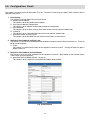
4-5. Configuration: Email
This screen is for setting up email notifications (Fig. 16). The email can be set-up for specific email receivers when a
specified event occurs.
1. Email Setting:
This section is to set the SNMP-32 card’s email Server.
A. Sender’s Email Address:
This section is to set the sender’s email address.
B. Email Server Requires Authentication:
This section is to set whether the email Server requires authentication.
C. Account Name:
This section is to set an email account name when the email server requires authentication.
D. Password:
This section is to set a password when the email server requires authentication.
E. Send Email When an Event Occurs:
This section is to set the SNMP-32 card to send an email when an event occurs.
2. Recipient’s Email Address (for Event Log):
This section is to set the email addresses for the recipients to receive an email when an event occurs. There can
be up to eight recipients.
A. Event:
This section is to select which events for the recipients to receive an email. Clicking on Select will open a
Select Events List.
3. Recipient’s Email Address (for Daily Report):
This section is to set the email addresses for the recipients to receive a Daily Report of the occurred events.
There can be up to four recipients.
A. Send Email for Daily Report (Format: hh.mm.ss):
This section is to set a particular time for the Daily Reports to be emailed.
Fig. 16-Email Screen
14
4-6. Configuration: PPP
This screen is to set the PPP dial-up information for the external modem (Fig. 17).
Fig. 17-PPP Screen
4-7. Configuration: Web/Telnet
This screen is to set-up the User Account information for Web/Telnet (Fig. 18).
1. User Account
A. User Name:
This section is to set a user name for the SNMP-32 card’s Web pages. There can be up to up to eight users.
The users have to input the user name and password to view the Web pages.
B. Password:
This section is to set a password for the SNMP-32 card’s Web pages. The users have to input the password
and the user name to view the Web pages.
C. Permission:
This section is to set the specified user’s authorizations of Read, or Read/Write.
D. IP Filter:
This section is to set a specific IP address for a certain user. This user can only view the Web pages from
the specified IP address. If you want the specified user to view the Web pages from any IP address, you can
set the IP Filter to *.*.*.*.
Fig. 18-Web/Telnet Screen
15
4-8. Configuration: System Time
This screen is to set the SNMP-32 card’s system time (Fig. 19).
1. Internet Time Setting
A. Time Between Automatic Updates:
This section is to set a time interval between automatic updates.
B. Primary Time Server:
This section is to set a Primary Time Server for the SNMP-32 card.
C. Secondary Time Server:
This section is to set a Secondary Time Server for the SNMP-32 card.
D. Time Zone (Relative to GMT):
This section is to set the correct time zone for different countries.
2. System Time (Format: mm/dd/yyyy hh:mm:ss):
This section is to set the system time manually for the SNMP-32 card.
Fig. 19-System Time Screen
4-9. Log Information: Event
1. Event Log
This screen shows a log of events for the connected device (Fig. 20). The log displays the Date/Time of the
event, the connected device and a description of the event. The SNMP-32 card can log up to 500 events. When
the 500 event limit is reached SNMP-32 card will delete the earliest event record and continue logging new
events. The following are the Event list for each connected device.
UPS Event List:
• Schedule Shutdown Event
• UPS Load Overrun
• UPS Communication Lost
• Turn Off UPS
• AC Power Failed
• UPS Battery Low
RPM Event List:
• RPM Communication Lost
• Outlet On
• Outlet Off
• Outlet Reboot
• Outlet Fault
16
ENV Event List:
• Environmental
• Environmental
• Environmental
• Environmental
Temperature Overrun
Temperature Underrun
Humidity Overrun
Humidity Underrun
CPS Event List:
• CPS Communication Lost
• Current Out of Threshold 1
• Current Out of Threshold 2
ATS Event List:
• Switch Input Power
Fig. 20-Event Log Screen
2. Save Event Log
This function is to save the current event log to another file for maintaining an Event Log History (Fig. 21).
Fig. 21-Save Event Log Screen
17
4-10.
Log Information: Data
1. Data Log
This screen shows the Data log for the connected UPS (Fig. 22). The log displays the Data/Time, Input Voltage,
Output Voltage, Input Frequency (Hz), Output Loading (%), Battery Capacity (%), and the Battery Temperature.
The SNMP-32 card can log up to 500 events. When the 500 event limit is reached SNMP-32 card will delete the
earliest log record and continue logging new Data.
Fig. 22-Data Log Screen
2. Save Data Log
This function is to save the current event log to another file for maintaining a Data Log History (Fig. 23).
Fig. 23-Save Event Log Screen
18
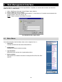
5. Firmware Upgrade Procedure
This section will guide you through the Firmware Upgrade Procedure of the SNMP-32 Card.
Æ
1. Open the ‘SNMP Utility’ group in the Windows ’Start’
‘Program Group’.
2. Click “SNMP Utility” to initiate the SNMP Utility program (Fig. 24).
Fig. 24-SNMP Utility Group
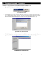
3. Once the SNMP Utility has been opened, the SNMP Utility will search for the network adapter automatically, or,
click on Network Selection from the main page. The screen will display the network adapter that was located.
Click on the network adapter, and then press “OK” to return to the main page of SNMP Utility (Fig. 25).
Fig. 25-SNMP Utility: Network Selection
4. The SNMP Utility will then search for and display all of the SNMP-32 cards that are on your LAN. Select the
appropriate SNMP-32 card on the right side of the screen, and then click “Download Firmware” (Fig. 26).
Fig. 26-SNMP Utility: Configuration Menu
19
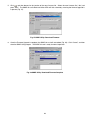
, and then browse for the location of the new firmware file. Select the new firmware file (*.bin) and
5. Click
press “Start”. The SNMP-32 card’s Red and Yellow LEDs will flash alternately, meaning the firmware upgrade is
in process (Fig. 27).
Fig. 27-SNMP Utility: Download Firmware
6. Once the Firmware Upgrade is complete, the SNMP-32 card will auto reboot (Fig. 28). Click “Cancel”, and then
close the SNMP Utility program. The SNMP-32 card is ready for normal operation.
Fig. 28-SNMP Utility: Download Firmware Complete
20
6. Telnet
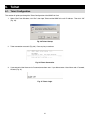
6-1. Telnet Configuration
This section will guide you through the Telnet Configuration of the SNMP-32 Card.
1. Select “Start” from Windows, click “Run”, then input Telnet and the SNMP-32 card’s IP Address. Then click “OK”
(Fig. 29).
Fig. 29-Telnet: Startup
2. Telnet connection successful (Fig. 30). Press any key to continue.
Fig. 30-Telnet: Connection
3. If you entered a User Name and a Password, enter them now. If you did not enter a User Name and a Password,
hit enter (Fig. 31).
Fig. 31-Telnet: Login
21
4. Telnet Main Menu screen (Fig. 32).
Fig. 32-Telnet: Main Menu
•
Set IP Address
This function is for setting the IP Address, the Gateway Address, and the Subnet Mask.
•
Set SNMP MIB System
This function is for setting the MIB System Group parameters.
•
Set SNMP Access Control
This function is for setting the IP Manager, the Community String, and the Access Permission.
Note: The configuration of ‘Set SNMP Access Control’ is only used for SNMP Network Manager.
•
Set SNMP Trap Notification
If you want to use a PC and perform the ‘Trap’ function of the SNMP manager to manage the RPM through
SNMP-32 card, the IP address of the PC must be added in this list of SNMP-32 card.
Note: The configuration of ‘Set SNMP Trap Receiver’ is only used for SNMP Network Manager.
•
Set System Time & Time Server
This function is for setting the System Date, and the System Time.
•
Set Web and Telnet User Account
This function is for setting the user’s account authorization.
•
Set Email
This function is for setting the email accounts to receive power event notification.
•
Reset Configuration to Default
This function is for setting all values to their default settings.
•
Save & Reboot
This function is for saving the current configuration (including any/all changes that were made) and then
rebooting the SNMP-32 card.
•
Exit Without Saving
This function is for exiting the configuration setup without saving any/all changes that were made.
22
7. Connected Device
7-1. Uninterruptible Power Supply (UPS)
This section will guide you through the SNMP-32 card’s UPS Web pages. See section 2, Installation Procedure, for
installing the SNMP-32 card in the UPS.
1. UPS Information
This screen shows the basic UPS information (Fig. 33). The UPS provides the values shown, or they are user
settings from the Configuration pages.
UPS Information
The UPS provides the following information: the Manufacturer, the Firmware Version, and the Model.
Battery Information
The UPS provides the values shown, or they are user settings from the Configuration pages.
Rating Information
The UPS provides the values shown, or they are user settings from the Configuration pages.
Fig. 33-UPS Information Screen
23
2. UPS Status
This screen shows the UPS’s current status (Fig. 34). The users can choose a time interval from the drop-down
box to refresh the status information.
UPS Status
This section is to show the UPS power status. The abnormal status will be displayed (in red) when there is an
abnormal power event.
Input Status
This section is to show the UPS input status (AC Status/Input Voltage/Input Frequency). The values will be
shown in red when an abnormal condition occurs.
Output Status
This section is to show the UPS output status (Output Voltage/Output Status/UPS Loading). The values will be
shown in red when an abnormal condition occurs.
Battery Status
This section is to show the UPS Battery Status (Temperature/Battery Status/Battery Capacity/Battery
Voltage/Time on Battery). The values will be shown in red when an abnormal condition occurs.
Fig. 34-UPS Status Screen
24
3. UPS Control
This screen is to provide remote UPS test functions (Fig. 35). Choose the test item and click on 'Apply' to
execute the test.
Quick Battery Test
The Quick Battery Test function will test the battery for 5-seconds.
General System Test
The General System Test function will test the UPS and the battery for-15 seconds. This test can only be
performed when the battery is fully charged.
Deep Battery Calibration
The Deep Battery Calibration function will test the UPS and the Battery until Low Battery Warning (LBW). When
this test is performed, the UPS will switch to the battery mode and operate until the Low Battery Warning alarm
occurs. Then the UPS will switch back to the normal AC mode.
Cancel Test
The Cancel Test function is to abort a test while the test is in progress.
Shutdown UPS (Battery mode only)
Selecting 'Shutdown UPS' will turn off the UPS. This function can only be performed in the battery mode. The
UPS will automatically restart when AC returns.
Put UPS in Sleep mode for XX minutes
When the UPS is in the Sleep mode, it will not provide power to the outlets. The UPS will restart once the Sleep
mode function is complete.
Cancel Shutdown
The Cancel Shutdown function is to abort a shutdown while a shutdown is in progress.
Audible alarm
• Disabled: Turn off the audible alarm.
• Enabled: Turn on the audible alarm.
• Muted: Mute the audible alarm until an event occurs (Fault, LBW).
• Disabled Until Low Battery Warning: Turn off the audible until a Low Battery Warning occurs.
Fig. 35-UPS Control Screen
25
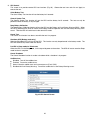
4. Graphic View
This screen displays the Temperature, the Capacity, the Load, the Voltage, etc of the UPS (Fig. 36). The three
bar graphs are Output Voltage, Output Load, and Input Voltage.
Fig. 36-Graphic View Screen
Clicking on the “Setting” button, the user can set the Upper Threshold and the Lower Threshold for the Output
Voltage, the Output Load, and the Input Voltage (Fig. 37).
Fig. 37-Set Thresholds Screen
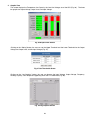
Clicking on the “Log Graphics” button, the user can observe the Input Voltage, Output Voltage, Frequency,
Loading, Capacity, and Temperature appearing within the X-Y coordinates (Fig. 38).
Fig. 38-Log Graphics Screen
26
5. UPS Settings
This screen is for the user to input information about the UPS (Fig. 39).
UPS Properties
The user can input the date of the last time the battery was replaced.
UPS Recorded
The user can set the time interval to log UPS Data.
Test UPS
The user can set the time interval for the UPS to perform a test.
Warning Threshold Value
Time Out of Connection Lost: The user can set the time interval for a warning of a lost connection.
Critical Loading: The user can set the warning threshold for an Overload condition.
Fig. 39-UPS Settings Screen
6. UPS Schedule
This screen allows the user to schedule a shutdown and a restart of the UPS (Fig. 40). To add a new schedule,
select the “New” button. To make changes to a current schedule, select [Edit]. To remove a schedule, select
[Delete].
Fig. 40-UPS Schedule Screen
27
After selecting the “New” button or [Edit], the following page will appear (Fig. 41). Select the desired shutdown
and restart configuration and then click the “Save” button.
•
•
•
Date: Input the date for the event to occur.
Time: Input the time for the event to occur on the specified date.
UPS Action: If Shutdown is selected, the UPS will shutdown, but will not restart automatically. If Shutdown
with Restart is selected, the UPS will shutdown and then restart after XX number of seconds.
Fig. 41-New Schedule Event Screen
7. RPM Action
This screen provides the interface to set the Remote Power Manager (RPM) to do a specific action when the
UPS or the ENV’s specified event occurs (Fig. 42).
Note: This function is only supported when the UPS or ENV is connected to the RPM.
Fig. 42-RPM Action Screen (1)
After selecting the “New” button the following page will appear (Fig. 43).
•
•
•
•
•
Events Select: The user can select which event to start the Action.
Events Action: The user can select to perform the Action when the event occurs or when the event is
removed.
RPM: The user can select which RPM to perform the Action.
Outlet: The user can select which outlet to perform the Action.
Outlet Action: The user can select to turn on the RPM’s outlet or turn off the RPM’s outlet.
Fig. 43-RPM Action Screen (2)
NOTE: RPM/UPS setup:
1. Plug the RPM’s power cord into the output of the UPS.
2. Install the SNMP-32 card into the RPM.
3. Install the RPM/UPS Interface card into the UPS.
4. Connect one end of the iLink cable to the iLink port on the RPM.
5. Connect the other end of the iLink cable to the iLink port on the RPM/UPS Interface card.
28
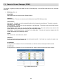
7-2. Remote Power Manager (RPM)
This section will guide you through the SNMP-32 card’s RPM Web pages. See the RPM User’s Manual for installation
instruction.
1. RPM Status (Fig. 44)
Select RPM
Select which RPM to view and control (RPM01-RPM16).
Outlet A-H
Name the outlet. The user can rename each individual outlet (see RPM Setting screen).
Outlet Control
Non-Internet: The outlet can only be controlled locally by the front panel control buttons. The outlets cannot be
controlled via the Web page.
Instant Shutdown: The outlet can only be controlled via the Web page. The outlet can be turned on/off instantly
by clicking on the outlet icon.
Safe Shutdown: The outlet can only be controlled via the Web page. The outlet will be turned off after XX
number of seconds by clicking on the outlet icon (see RPM Setting screen).
Safe Reboot: The outlet can only be controlled via the Web page. The outlet will turned on (reboot) after XX
number of seconds (see RPM Setting screen).
On/Off
This is the current state of the outlet, on/off.
Outlet Icon
Clicking on the Outlet Icon will change the state of the outlet (on/off). If the Outlet Icon is yellow, the outlet is on.
If the Outlet Icon is white, the outlet is off.
All On Button
Clicking on the All On button will turn all of the outlets on, when the outlets are setup for Internet control.
All Off Button
Clicking on the All Off button will turn all of the outlets off, when the outlets are setup for Internet control.
Fig. 44-RPM Status Screen
29
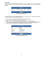
2. RPM Setting (Fig. 45)
Select RPM
Select the appropriate RPM to configure (RPM01-RPM16).
Address Change
Change the RPM’s ID. The factory default setting is RPM00, which is not configurable. The user must change
the RPM’s ID to RPM01 through RPM16.
Identification
The user can rename the RPM.
Outlet
Outlet Identification.
Name
The user can rename the individual outlets.
Phone controllable
The user can configure each outlet to be telephone controllable.
Control Type
• Instant Shutdown: When the outlet is turned off, the outlet will shutdown immediately.
• Safe Shutdown: When the outlet is turned off, there will be a time delay (before the outlet turns off)
according to the value in the “Power Off Delay” field.
• Safe Reboot: When the outlet is turned off, there will be a time delay (before the outlet turns on again)
according to the value in the “Power Resume Delay” field.
Power off Delay
There will be a time delay before the outlet turns off according to the value in this field.
Power Resume Delay
There will be a time delay before the outlet turns on according to the value in this field.
Fig. 45-RPM Setting Screen
30
3. RPM Schedule
This screen is for scheduling the RPM’s outlets to perform a specific Action (Fig. 46). To add a new schedule,
select the “New” button. To make changes to the current schedule, select [Edit]. To remove a schedule, select
[Delete].
Fig. 46-RPM Schedule Screen
After selecting the “New” button or [Edit], the following screen will appear (Fig. 47). Select the desired shutdown
and restart configuration and then click the Save button.
•
•
•
•
•
RPM: The user can select which RPM to perform the Action (RPM01-RPM16).
Outlet: The user can select which outlet to perform the Action.
Outlet Action: The user can select to turn on the RPM’s outlet or turn off the RPM’s outlet.
Date: The user can configure the RPM to perform the Action ‘Once’ on the specified date (format:
mm/dd/yyyy) or the RPM can be configured to perform the Action ‘Every’ week on the specified day.
Time: The user can select the time of day to perform the Action (format: 24-hour).
Fig. 47-New Schedule Event Screen
31
7-3. Current Probe Sensor (CPS)
This section will guide you through the SNMP-32 card’s CPS Web pages. See the CPS User’s Manual for installation
instruction.
1. CPS Status (Fig. 48)
This screen shows the electrical current detected by CPS and indicates if the current is out of the preset range.
Fig. 48-CPS Status Screen
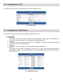
2. CPS Configuration (Fig. 49)
Name
The user can rename the CPS.
Threshold 1
The user can set the out-of-tolerance value for the first phase.
Threshold 2
The user can set the out-of-tolerance value for the second phase.
Fig. 49-CPS Configuration Screen
32
7-4. Temp/Hum32-Probe (ENV)
This section will guide you through the SNMP-32 card’s ENV Web pages. See the Temp/Hum32-Probe User’s Manual
for installation instruction.
1. ENV Status (Fig. 50)
This screen shows the temperature and the humidity detected by ENV. The user can select the time interval for
refreshing the ENV Status screen. When there is an environmental condition that is out-of-tolerance, it will
appear in red.
Fig. 50-ENV Status Screen
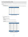
2. ENV Configuration (Fig. 51)
The user can define the out-of-tolerance range for the temperature and the humidity. If the temperature or
humidity exceeds the out-of-tolerance range, the SNMP-32 card can be configured to perform an action, such as
email, sending traps, or trigger the RPM to control the power.
Fig. 51-ENV Configuration Screen
33
7-5. Automatic Transfer Switch (ATS)
This section will guide you through the SNMP-32 card’s ATS Web pages. See the ATS User’s Manual for installation
instruction.
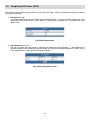
1. ATS Status (Fig. 52)
This screen is to show which Input Power Source is being used. Clicking on the “ICON” can switch the input
power source from Input Power Source A to Input Power Source B.
Fig. 52-Automatic Transfer Switch Screen
2. ATS Configuration (Fig. 53)
Identification
The user can define the name of the ATS.
Input Power Source A
The user can define the name of the Input Power Source A.
Input Power Source B
The user can define the name of the Input Power Source B.
Fig. 53-ATS Configuration Screen
34
8. Configuring the NMS
To complete the SNMP-32 card installation and configuration process, you must compile the necessary MIBs to configure
the NMS.
Most NMS with a MIB compiler can manage the SNMP-32 card. For instructions on how to compile MIBs for the most
popular NMS—HP OpenView Network Node Manager and SunConnect SunNet Manager, see the corresponding heading
below.
General Network Management Stations
Follow these general procedures to configure an NMS:
1. Compile the device MIBs.
2. Add the SNMP-32 card object to the Management Map.
3. Ping the SNMP-32 card.
HP OpenView Network Node Manager for HP-UX
Compile the Device MIB
1.
2.
3.
4.
5.
6.
Copy the UPS MIB file from the TAR formatted diskette into the subdirectory /usr/OV/snmp_mibs.
From the main menu, select Options
Load/Unload MIBs: SNMP...
Select Load.
Select the MIB file copied earlier.
Select OK.
Add the SNMP-32 card Object to the Management Map
1.
2.
3.
4.
5.
6.
7.
8.
9.
10.
Select the submap then Edit: Add Object.
Select the group computer.
With the middle (or opposite) mouse button, drag the generic symbol subclass device to the submap.
Enter a name for the object in the Selection and Label fields of the Add Object box.
Highlight IP Map from Object Attributes group.
Select Set Object Attributes button.
Enter Host name and IP address of SNMP-32 card adapter.
Enter OK.
Enter OK at Add Object menu.
Enter OK at Add Object:palette.
Poll the Device OIDs
1. From the main menu, select Monitor: MIB values then Browse MIB: SNMP.
2. Move around the MIBs to view the UPS device information.
Set the Device OIDs
1. From the main menu, select Monitor: MIB values then Browse MIB: SNMP.
2. Select a MIB variable you want to alter by clicking on it.
3. Enter the new value then click on Set.
4. Click on Start Query to view the changes.
Ping the SNMP-32 card
1.
2.
Change active Window to Shell.
Type ping <IP address> and press <enter>.
35
9. Appendix
This section discusses: Communities, Gateways, IP Addresses, and Subnet masking.
Communities
A community is a string of printable ASCII characters that identifies a user group with the same access privileges. For
example, a common community name is “public.”
For security purposes, the SNMP agent validates requests before responding. The agent can be configured so that only
trap managers that are members of a community can send requests and receive responses from a particular community.
This prevents unauthorized managers from viewing or changing the configuration of a device.
Gateways
Gateway, also referred to as a router, is any computer with two or more network adapters connecting to different physical
networks. Gateways allow for transmission of IP packets among networks on an Internet.
IP Addresses
Every device on an Internet must be assigned a unique IP (Internet Protocol) address. An IP address is a 32-bit value
comprised of a network ID and a host ID. The network ID identifies the logical network to which a particular device
belongs. The host ID identifies the particular device within the logical network. IP addresses distinguish devices on an
Internet from one another so that IP packets are properly transmitted.
IP addresses appear in dotted decimal (rather than in binary) notation. Dotted decimal notation divides the 32-bit value
into four 8-bit groups, or octets, and separates each octet with a period. For example, 199.217.132.1 is an IP address in
dotted decimal notation.
To accommodate networks of different sizes, the IP address has three divisions—Classes A for large, B for medium, and
C for small. The difference among the network classes is the number of octets reserved for the network ID and the
number of octets reserved for the host ID.
Class
A
B
C
Value of First Octet
1-126
128-191
192-223
Network ID
First octet
First two octets
First three octets
Host ID
Number of Hosts
Last three octets
16,387,064
Last two octets
64,516
Last octet
254
Any value between 0 and 255 is valid as a host ID octet except for those values the InterNIC reserves for other purposes.
Value
0, 255
127
224-254
Purpose
Subnet masking
Loopback testing and interprocess communication on local devices
IGMP multicast and other special protocols
Subnetting and Subnet Masks
Subnetting divides a network address into sub-network addresses to accommodate more than one physical network on a
logical network.
For example: A Class B company has 100 LANs (Local Area Networks) with 100 to 200 nodes on each LAN. To classify
the nodes by its LANs on one main network, this company segments the network address into 100 sub-network
addresses. If the Class B network address is 150.1.x.x, the address can be segmented further from 150.1.1.x through
150.1.100.x.
36
A subnet mask is a 32-bit value that distinguishes the network ID from the host ID for different sub-networks on the same
logical network. Like IP addresses, subnet masks consist of four octets in dotted decimal notation. You can use subnet
masks to route and filter the transmission of IP packets among your sub-networks. The value “255” is assigned to octets
that belong to the network ID, and the value “0” is assigned to octets that belong to the host ID.
For the example above, if you want all the devices on the sub-networks to receive each other’s IP packets, set the subnet
mask to 255.255.0.0. If you want the devices on a single sub-network only to receive IP packets from other devices on
its own sub-network, set the subnet mask to 255.255.255.0 for the devices on that sub-network.
Subnet Mask
0.0.0.0
Routing and Filtering
IP packets are transmitted to all devices.
IP packets are only transmitted to devices that are IP that’s first octet
255.0.0.0
matches the sender’s IP address’s first octet.
IP packets are only transmitted to devices that are IP that’s first two
255.255.0.0
octets match the sender’s IP address’s first two octets.
IP packets are only transmitted to devices that are IP that’s first three
255.255.255.0 octets match the sender’s IP address’s first three octets.
37
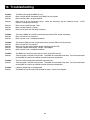
10. Troubleshooting
Problem:
Solution:
Solution:
Solution:
The NMS cannot ping the SNMP-32 card.
Make sure the network connection to the SNMP-32 card is good.
Make sure the cable is in good condition.
Make sure to set the Community String. Name the community with any lowercase name. A UPS
monitors a designated community.
Make sure to set the Manager Table.
Make sure the Gateway is correct.
Make sure to Save after the Setup Procedure.
Problem:
Solution:
Solution:
The internal SNMP-32 card will not communicate and the LEDs are not illuminated.
Make sure the UPS is turned ON.
Make sure this is not a scheduled shutdown.
Problem:
Solution:
Solution:
Solution:
Solution:
The external SNMP-32 card will not communicate and the LEDs are not illuminated.
Make sure the UPS is turned ON.
Make sure that the external power adaptor is plugged into the UPS.
The power adaptor could be bad. Contact Tech Support.
Make sure this is not a scheduled shutdown.
Problem:
Solution:
The SNMP-32 card will not communicate and all of the LEDs are ON.
There has been a collision of the packets. The SNMP-32 card needs to be reset. Press the reset button
on the SNMP-32 card for ten seconds and then release the reset button.
Problem:
Solution:
The user cannot change from one Web Page to the next.
There has been a collision of the packets. The SNMP-32 card needs to be reset. Press the reset button
on the SNMP-32 card for ten seconds and then release the reset button.
Problem:
Solution:
I forgot my Supervisor’s name/password.
The SNMP-32 card will need to be returned for repair. Contact Tech Support.
Solution:
Solution:
Solution:
38
11. Obtaining Technical Assistance
For Technical Support on the Web, please visit the Support section of our Web site
or visit our online Discussion Forum at www.minutemanups.com
In order to diagnose the problem you are having, our technicians need the following information from you.
Installation Site:
Company Name:
Address:
State:
City:
ZIP code:
Contact Person’s Name:
Phone Number:
If you are a consultant,
Consultant Name:
Phone Number:
Fax Number:
Computer System:
Operating System and version:
System Manufacturer:
System Model Number:
NMS name and revision number:
UPS:
Model Name/Number:
Serial Number:
Type of SNMP Card (internal or external):
What are the symptoms?
Technical Support Please have the information listed above ready when you contact us. You can reach us by calling:
Phone: 1-972-446-7363
Fax: 1-972-446-9011
39
12. Limited Product Warranty
LIMITED PRODUCT WARRANTY
Para Systems Inc. (Para Systems) warrants this equipment, when properly applied and operated within specified
conditions, against faulty materials or workmanship for a period of three years from the date of original purchase by the
end user. For equipment sites within the United States and Canada, this warranty covers repair or replacement of
defective equipment at the discretion of Para Systems. Repair will be from the nearest authorized service center.
Replacement parts and warranty labor will be borne by Para Systems. For equipment located outside of the United
States and Canada, Para Systems only covers faulty parts. Para Systems products repaired or replaced pursuant to this
warranty shall be warranted for the remaining portion of the warranty that applies to the original product. This warranty
applies only to the original purchaser who must have properly registered the product within 10 days of purchase.
The warranty shall be void if (a) the equipment is damaged by the customer, is improperly used, is subjected to an
adverse operating environment, or is operated outside the limits of its electrical specifications; (b) the equipment is
repaired or modified by anyone other than Para Systems or Para Systems-approved personnel; or (c) has been used in a
manner contrary to the product's operating manual or other written instructions.
Any technical advice furnished before or after delivery in regard to use or application of Para Systems’s equipment is
furnished without charge and on the basis that it represents Para Systems’s best judgment under the circumstances, but
it is used at the recipient's sole risk.
EXCEPT AS PROVIDED HEREIN, PARA SYSTEMS MAKES NO WARRANTIES, EXPRESSED OR IMPLIED,
INCLUDING WARRANTIES OF MERCHANTABILITY AND FITNESS FOR A PARTICULAR PURPOSE. Some states
do not permit limitation of implied warranties; therefore, the aforesaid limitation(s) may not apply to the purchaser.
EXCEPT AS PROVIDED ABOVE, IN NO EVENT WILL PARA SYSTEMS BE LIABLE FOR DIRECT, INDIRECT,
SPECIAL, INCIDENTAL, OR CONSEQUENTIAL DAMAGES ARISING OUT OF THE USE OF THIS PRODUCT, EVEN
IF ADVISED OF THE POSSIBILITY OF SUCH DAMAGE. Specifically, Para Systems is not liable for any costs, such as
lost profits or revenue, loss of equipment, loss of use of equipment, loss of software, loss of data, cost of substitutes,
claims by third parties, or otherwise. The sole and exclusive remedy for breach of any warranty, expressed or implied,
concerning Para Systems’s products and the only obligation of Para Systems hereunder, shall be the repair or
replacement of defective equipment, components, or parts; or, at Para Systems’s option, refund of the purchase price or
substitution with an equivalent replacement product. This warranty gives you specific legal rights and you may also have
other rights, which vary from state to state.
40