1
12000E IP Broadband Loop Carrier
Installation Instructions
Document Number IPD1-A2-ZZ40-20
October 2005
Contents
End User License Agreement (Zhone and Affiliates) 2
Introduction 4
Unpacking and Inspecting the Equipment 4
Installation Options 5
Installing Your Management Module 7
Installing Your Interface Module(s) 10
Establishing Your Uplink Connections 14
Connecting Your Subscriber Lines 15
Configuration and Management 18
Fan Module 19
Specifications 20
Important Safety Instructions 20
EMI Notices 22
Notice to Users of the Canadian Telephone Network 23
CE Marking 23
Product Documentation Online 23
Contacting Global Service and Support 23
Technical Support 24
Service Requirements 24
Zhone Technologies
@Zhone Way
7001 Oakport Street
Oakland, CA 94621
USA
Copyright © 2005
Zhone Technologies, Inc.
1
End User License Agreement (Zhone and Affiliates)
Do not install this Software unless you agree to these provisions.
Return the Software promptly for a refund if you do not agree.
License. Zhone Technologies, Inc. and/or an affiliate ("Zhone") hereby grants
you ("User")—either an individual or a single business entity—the
non-exclusive right to install, access, run, or interact with ("Use") one copy of
the enclosed software (which may have been, or may be, provided on media,
as part of a hardware platform, through download, or otherwise) and
associated documentation ("Software") on the first computer system on which
User installs the Software ("System") solely for internal business purposes
(including, without limitation, providing products and services to User's
customers) and subject to the restrictions below). Zhone may, in its sole
discretion, make available future updates or upgrades to the Software each of
which is also Software subject hereto. Title to and all patent rights, copyrights
and other intellectual property rights in the Software are retained by Zhone
and its direct and indirect suppliers and licensors ("Licensors").
Restrictions. The Software may not be (a) Used on or from any system other
than the System; (b) Used with more than any maximum number of
subscribers stated in the documentation accompanying the Software; (c) Used
so as to circumvent any technological measure included therein or provided
by Zhone from time to time to control access to or limit use of the Software;
(d) sublicensed, rented, leased or lent to third parties; (e) imported or exported
into any jurisdiction except in compliance with all applicable laws of the
United States and such jurisdiction; (f) transferred to a third party unless (A)
User transfers the original and all surviving copies to a third party who has
agreed in writing to be bound hereby and (B) such third party pays to Zhone
such reasonable additional fee as Zhone may impose from time to time with
respect to such transfer; or (g) made available to third parties as part of any
time-sharing or service bureau arrangement. User shall not have the right to
use the Software or any portion thereof for a use other than that contemplated
by its documentation. User will not copy all or any part of the Software or
attempt, or encourage or permit any third party, to modify, adapt, make
derivative works from, reverse engineer, reverse compile, disassemble or
decompile the Software or any portion thereof except and only to the extent
that such activity is expressly permitted by law notwithstanding this
limitation. Violation of any of the foregoing shall be deemed a material breach
hereof. User may make a reasonable number of copies solely for archival or
disaster recovery and subject to the restrictions imposed by copyright law, but
may not modify or otherwise copy the Software. User agrees to reproduce
product identification, copyright and other proprietary notices of Zhone and
Licensors on all copies. User's rights are only as expressly stated herein.
Zhone may immediately terminate your rights if you violate the provisions
hereof.
2
12000E IP Broadband Loop Carrier Installation Instructions
IPD1-A2-ZZ40-20
End User License Agreement (Zhone and Affiliates)
Limited Warranty. Zhone warrants that the media containing the Software is
free from defects in material and workmanship for ninety (90) days following
your purchase of the Software. You may provide written notice of such defect
(addressed to Zhone Technologies, Inc., Attention: Customer Service, 7001
Oakport Street @ Zhone Way, Oakland, CA 94621) no later than ten (10) days
following expiration of such period and, as your sole and exclusive remedy,
Zhone will provide replacement media. NEITHER ZHONE NOR ITS
LICENSORS MAKE ANY OTHER WARRANTY, EXPRESS, IMPLIED
OR STATUTORY. ZHONE AND ITS LICENSORS DISCLAIM ALL
WARRANTIES OF FITNESS FOR PARTICULAR PURPOSE,
MERCHANTABILITY AND NON-INFRINGEMENT. Some states or other
jurisdictions do not allow the exclusion of implied warranties on limitations
on how long an implied warranty lasts, so the above limitations may not apply
to you. This warranty gives you specific legal rights, and you may also have
other rights which vary from one state or jurisdiction to another.
Limit of Liability. In case of any claim hereunder or related to the Software,
neither Zhone nor its Licensors shall be liable for direct damages exceeding
the price paid by User for the Software or for special, incidental,
consequential or indirect damages, even if advised in advance of the potential
thereof.
U.S. Government Users. The Software is a "commercial item" as defined at
48 C.F.R. 2.101, consisting of "commercial computer software" and
"commercial computer software documentation" as such terms are used in 48
C.F.R. 12.212. Under 48 C.F.R. 12.212 and 48 C.F.R. 227.7202-1 to
227.7202-4, U.S. Government Users acquire the Software only with the rights
set forth therein.
Third Party Licensors. This Zhone End User License Agreement may be
accompanied by differing or additional provisions applicable to portions of
the Software provided by one or more Licensors ("Licensor Provisions").
User acknowledges and agrees that its Use of such portions of the Software is
subject to the Licensor Provisions.
IPD1-A2-ZZ40-20
12000E IP Broadband Loop Carrier Installation Instructions
3
Introduction
The 12000E IP Broadband Loop Carrier (BLC) provides a high capacity and
native IP Ethernet foundation for a variety of feature-rich multi-service access
multiplexer modules.
The 12000E BLC is engineered for efficient, high-speed IP data transport in a
compact, fully fault-tolerant chassis. It features a high capacity backplane
delivering up to 48 Gbps throughput and providing a non-blocking
architecture for even the highest bandwidth broadband access technologies,
such as ADSL2+.
The 12000E BLC supports single or dual redundant uplink, management, and
switching modules. In redundant mode, both modules can be connected to the
dual backplanes with redundant modular backhaul/uplink ports to support 10/
100 Ethernet, GigE (Copper or fiber), T1/E1, and dual bonded T1/E1 uplink
modules.
For flexibility of installation the 12000E has removable mounting brackets
that can be placed in increments of 1.45” up to 9.28” from the front of the
chassis, allowing for multiple installation options in either 19" or 23"
equipment racks.
Unpacking and Inspecting the Equipment
HANDLING PRECAUTIONS FOR
! STATIC-SENSITIVE DEVICES
This product is designed to protect sensitive components from
damage due to electrostatic discharge (ESD) during normal
operation. When performing installation procedures, however, take
proper static control precautions to prevent damage to equipment. If
you are not sure of the proper static control precautions, contact your
nearest sales or service representative.
The following components should be included in the shipping container:
z
1 – 12000E with 1 fan module and 12 slot covers
z
4 – Rubber Bumper Screws
z
2 – Rack Mount Brackets (either 19" or 23", as ordered)
z
10 – #6 Phillips Bracket Screws
z
8 – #10 Phillips Rack Screws
z
8 – #12 Phillips Rack Screws
If there is visible damage, do not attempt to connect the device. Contact your
sales representative.
4
12000E IP Broadband Loop Carrier Installation Instructions
IPD1-A2-ZZ40-20
Installation Options
Installation Options
The 12000E BLC is designed for installation in a Restricted Access area
where admittance is limited to trained and authorized service personel. It may
be installed on a tabletop or in a rack.
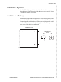
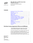
Installation on a Tabletop
Insert the four provided rubber bumper screws into the mounting holes at the
bottom of the 12000E chassis for surface grip and airflow. Position and secure
all connecting cables such that they will not become a tripping hazard or pull
loose from the chassis. Ensure that the air supply vents around the top and
bottom edges of the chassis are not blocked.
12000E Bottom View
Rubber Bumper
Screw
Side
Top
05-17800
Front
IPD1-A2-ZZ40-20
Rear
12000E IP Broadband Loop Carrier Installation Instructions
5
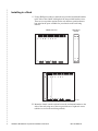
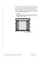
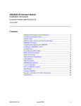
Installing in a Rack
1 Using a Phillips screwdriver, attach the two provided rack mount brackets
to the sides of the 12000E with eight of the ten provided bracket screws.
There are seven position options for the rack brackets; position them as
best suited to the space available for your chassis on the rack being
utilized.
12000E Side View
Front
Rack Mount
Bracket
Rear
05-17802
2 Mount the chassis onto the rack and secure the rack mount brackets to the
sides of the rack using one of the two provided sets of eight rack screws
(whichever size fits the rack being utilized).
6
12000E IP Broadband Loop Carrier Installation Instructions
IPD1-A2-ZZ40-20
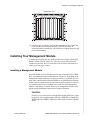
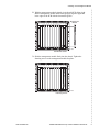
Installing Your Management Module
12000E Front View
1
2
3
4
5
6
7
8
12000E
9 10 11 12 U1 U2
05-17802
3 Check the rack for stability, ensuring that installation of the 12000E has
not caused the rack to become top-heavy. Position and secure all
connecting cables such that they will not become a tripping hazard or pull
loose from the chassis.
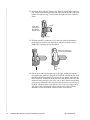
Installing Your Management Module
A management module provides the functional control for the 12000E BLC;
the BLC cannot function without one. There are several different models
available for purchase. Refer to www.zhone.com for further information, or
contact your sales representative.
Installing a Management Module
An uplink module provides the upstream network connection for the12000E
BLC; a management module cannot function without one. Depending on the
management module model that you plan to install in your 12000E, you will
need either a Media Interface Module (MIM) or an Uplink Interface Module
(UIM). Only one uplink module is required for operational purposes, however
two uplink modules may be installed, one in each port of the management
module, if redundancy is desired. Refer to your management module and/or
uplink module installation instructions for further information.
CAUTION:
If a slot cover is removed from a management module uplink port, it must
be replaced with an uplink module. DO NOT OPERATE A 12000E BLC
WITH A MANAGEMENT MODULE THAT HAS AN OPEN UPLINK
PORT.
IPD1-A2-ZZ40-20
12000E IP Broadband Loop Carrier Installation Instructions
7
1 Select a slot for installation. The 12000E is a fourteen slot chassis: slots
1–12 are reserved for interface modules and slots U1–U2 are reserved for
management modules. Although the 12000E is shipped with Port U1
open, your management module can be installed in either Port U1 or Port
U2. Only one management module is required for operational purposes.
However, two management modules may be installed if redundancy is
desired: one in Slot U1 and one in Slot U2.
CAUTION:
If the slot cover is removed from Slot U2, it must be replaced with a
management module. DO NOT OPERATE YOUR 12000E WITH
AN EMPTY MODULE SLOT.
1
2
3
4
5
6
7
8
12000E
9 10 11 12 U1 U2
05-17803
Management Module Slots
8
12000E IP Broadband Loop Carrier Installation Instructions
IPD1-A2-ZZ40-20
Installing Your Management Module
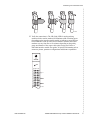
2 With the management module printed circuit board (PCB) facing right
and the management module model name upright, align the upper and
lower edges of the PCB with the slot module guides.
1
2
3
4
5
6
7
8
12000E
9 10 11 12 U1 U2
Management
Module
MUM
05-17804
Slot Module Guides
3 Slide the management module firmly into the chassis. Tighten the
fastening screws on the management module faceplate.
1
2
3
4
5
6
7
8
12000E
9 10 11 12 U1 U2
MUM
05-17805
Fastening Screws
IPD1-A2-ZZ40-20
12000E IP Broadband Loop Carrier Installation Instructions
9
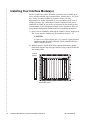
Installing Your Interface Module(s)
Interface modules provide the subscriber connections for an 12000E; up to
twelve interface modules may be installed in the 12000E (slots 1–12). There
are a variety of models available for purchase; contact your sales
representative for further information or visit www.zhone.com for a list of
available products. Any combination of interface module models may be
installed in an 12000E as long as they are supported by the model type and
version number of your management module; refer to the Release Notes for
your particular management module model for compatibility information.
1 Select a slot for installation. Although the 12000E is factory shipped with
Slot 1 open, interface modules may be installed in any slot, 1–12.
CAUTION:
If a slot cover is removed from slot 2–12, it must be replaced with an
interface module. DO NOT OPERATE YOUR 12000E WITH AN
EMPTY MODULE SLOT.
2 With the interface module PCB facing right and the interface module
model name upright, align the upper and lower edges of the PCB with the
slot module guides.
Interface
Module
1
2
3
4
5
6
7
8
12000E
9 10 11 12 U1 U2
PWR
TIM
MUM
05-17806
Slot Module Guides
10
12000E IP Broadband Loop Carrier Installation Instructions
IPD1-A2-ZZ40-20
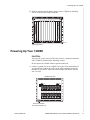
Powering Up Your 12000E
3 Slide the interface module firmly into the chassis. Tighten the fastening
screws on the interface module faceplate.
1
2
3
4
5
6
7
8
12000E
9 10 11 12 U1 U2
PWR
TIM
MUM
05-17807
Fastening Screws
Powering Up Your 12000E
CAUTION:
Turn your DC power source(s) OFF until you have completed connection
of the 12000E as outlined in the following sections.
Do not operate the 12000E without a ground connection.
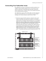
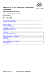
1 Connect a ground wire to the 12000E: Line up the 2-hole terminal lug of
your ground wire with the two holes on the small, unpainted section on
the back of your chassis. Secure the terminal lug to the chassis with two
#10-32 screws.
12000E Rear View
48V
30A
48V
30A
12B 11B 10B
9B
8B
7B
6B
5B
4B
3B
2B
1B
12A 11A 10A
9A
8A
7A
6A
5A
4A
3A
2A
1A
05-17808
Ground Connection
for 2-Hole Terminal Lug
IPD1-A2-ZZ40-20
12000E IP Broadband Loop Carrier Installation Instructions
11
Ground Connection Close-up
05-17809
2 Connect the ground wire to a frame ground. Ground wire connection can
vary from location to location though typically all equipment in a Central
Office is grounded to a common copper bus.
3 Select a terminal block. Either terminal block on the back of the 12000E
may be used to power the chassis; only one terminal block is required for
operational purposes. The two terminal blocks on the 12000E are
independent feeds. Chassis power is supplied by only one terminal block
at a time; the second supply is a backup. Likewise, the two terminal
blocks do not load-share. Each terminal block must be supplied with
adequate amperage to run the chassis independently.
CAUTION:
Two identical terminal blocks are provided on the 12000E chassis to
allow for redundant 48V DC power sources. Each power source to be
connected with the 12000E must be equipped with a disconnect
device such as an On/Off switch, or, an appropriately rated circuit
breaker must be installed on each power circuit to be used. Hazardous
voltages will not be removed from the 12000E until all power sources
have been either turned off or disconnected from the chassis.
DC Terminal Block
DC Terminal Block
48V
30A
48V
30A
12B 11B 10B
9B
8B
7B
6B
5B
4B
3B
2B
1B
12A 11A 10A
9A
8A
7A
6A
5A
4A
3A
2A
1A
05-17810
12
12000E IP Broadband Loop Carrier Installation Instructions
IPD1-A2-ZZ40-20
Powering Up Your 12000E
4 Using a Phillips screwdriver, remove the left-hand screw from the chosen
terminal block (labeled "+" on the chassis). Slide the ring terminal of your
positive power lead around the shaft of the screw and insert the screw into
the same "+" terminal from which it was removed.
DC Power Terminal
Positive (+) Terminal
48
V
30A
Positive Power Lead
Ring Terminal
48
V
30A
05-17811
5 Remove the right-hand screw (labeled "–") from the same terminal block.
Slide the ring terminal of your NEGATIVE lead around the shaft of the
screw and re-insert the screw into the same "–" terminal from which it
was removed.
DC Power Terminal
Negative () Terminal
48
V
30A
48
V
30A
05-17812
Negative Power Lead
Ring Terminal
CAUTION:
Observe proper polarity.
6 Connect both power leads to a fuse panel. The negative (–) lead connects
to a "Batt" (Battery) terminal and the positive (+) lead connects to a
"Return" terminal on your DC power supply.
IPD1-A2-ZZ40-20
12000E IP Broadband Loop Carrier Installation Instructions
13
7 Verify the connection. Turn your power source(s) on. The PWR (power)
LED on the interface module and management module faceplates will
illuminate solid green to indicate the modules are receiving power.
Management
Module
Interface
Module
MULTIPLEXER
UPLINK
MODULE
T1
INVERSE
MULTIPLEXER
Power LED
PWR
FAN
PWR
Lnk
Act
Dplx
05-17813
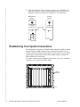
Establishing Your Uplink Connections
No configuration is necessary for Uplink Interface Modules (UIMs) or Media
Interface Modules (MIMs) installed on the management module(s) in your
12000E to operate at default settings. However, if you wish to run your uplink
connections at settings other than the UIM or MIM defaults, configure the
UIM or MIM prior to connection.
For further connection and configuration information, refer to the installation
instructions of your particular UIM or MIM.
1
2
3
4
5
6
7
8
12000E
9 10 11 12 U1 U2
MULTIPLEXER
UPLINK
MODULE
PWR
FAN
PWR
Lnk
Act
Dplx
TIM
Uplink
Module
MUM
05-17814
14
12000E IP Broadband Loop Carrier Installation Instructions
IPD1-A2-ZZ40-20
Connecting Your Subscriber Lines
Connecting Your Subscriber Lines
No configuration is necessary for the interface module(s) installed in your
12000E to operate at default settings. However, if you wish to run your
subscriber connections at settings other than the defaults, configure the
interface module(s) prior to connection. Refer to the installation instructions
for your particular interface module(s).
The 12000E chassis supports ADSL, IDSL, SDSL and T1/E1 technologies.
Ensure that the subscriber lines you are connecting correspond with the
technology of the interface module(s) installed in your 12000E.
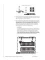
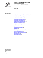
1 Identify the Appropriate RJ21 Connector(s). Subscriber lines must be
connected according to the 12000E slot in which the corresponding
interface module was installed. Interface module slots 1–12 run from left
to right when you are facing the front of the chassis; the corresponding
RJ21 ports are directly behind each slot on the back of the chassis (1–12,
right to left, when you are facing the back of the chassis). Each interface
module slot on the 12000E has two corresponding RJ21 connectors
located on the back of the chassis. The bottom row of RJ21 connectors
(A) provides the connection for interface module ports 1–24 (on most
models) and the top row of RJ21 connectors (B) provides the interface
module connection for ports 25–48 (on applicable models). For the
TIM1500-24 interface module, the A connector provides connection for
ports 1–12 and the B connector provides the connection for ports 13–24.
12000E Rear View
48V
30A
48V
30A
B Connectors
12B 11B 10B
9B
8B
7B
6B
5B
4B
3B
2B
1B
12A 11A 10A
9A
8A
7A
6A
5A
4A
3A
2A
1A
Subscriber
connections
for interface module
ports 25-48 (on
applicable models)
A Connectors
Subscriber
connections
for interface module
ports 1-24 (on
applicable models)
05-17815
IPD1-A2-ZZ40-20
12000E IP Broadband Loop Carrier Installation Instructions
15
2 Detach the hook-and-loop fastener strap from the female RJ21 connector
port: lift the hook-and-loop fastener tab on the left and pull the strap open
towards the right, leaving it looped under the right side of the connector
frame.
Femle RJ21
Connector A
for Interface
Module Slot 3
05-17816
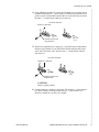
3 Slide the male RJ21 connector of your interface cable underneath the
hook-and-loop fastener, from the bottom, and press it firmly into the
female RJ21 connector port on the chassis.
Male RJ21 Connector
of your Interface Cable
05-17817
4 Pull the hook-and-loop fastener strap to the right, making sure that it is
snug against the connector, then pull the strap back towards the left, such
that the hook-and-loop fastener layers stick to one another across the top
of the connector. Tuck the tab at the end of the strap down to the left of the
connector frame so that it is out of the way of other connections and then
screw the top of the RJ21 cable connector into the jack screw at the top of
the RJ21 connector frame on the chassis. Note: If you are using a 120 or
180 degree cable, both the top and the bottom of the cable connector
should be screwed to the RJ21 connector frame on the chassis.
16
12000E IP Broadband Loop Carrier Installation Instructions
IPD1-A2-ZZ40-20
Connecting Your Subscriber Lines
05-17818
5 Verify the connection(s). The LK (Link) LED for each port being
connected with a remote modem will illuminate solid or flashing green
(depending on the interface module model) to indicate a connection has
been established. Link up time between interface modules and remote
modems can vary from one to five minutes depending on the quality,
gauge and distance of the copper cable pair(s) being used. Refer to
individual interface module user guides for specific information such as
connector pinouts, parameter configurations and distance capabilities.
T1
INVERSE
MULTIPLEXER
PWR
RX TX AL LK
1
2
3
4
5
6
7
8
9
10
05-17819
IPD1-A2-ZZ40-20
12000E IP Broadband Loop Carrier Installation Instructions
17
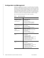
Configuration and Management
Although no configuration is necessary to run subscriber lines at the default
settings, all 12000E parameter settings are software selectable via Command
Line Interface (CLI), Simple Network Management Protocol (SNMP), or the
Network Management System (NMS), depending upon the capabilities of the
management module model installed in your chassis. Once the management
module has been initialized, interface modules may be configured as desired
via whichever system(s) your management module is capable of running.
Refer to the following documentation for further information:
Table 1:
User Documentation
Document
Management module
installation instructions
Contents
z
(model-specific)
Uplink module
installation instructions
z
(model-specific)
Interface module user
guides
z
(model-specific)
CLI Management User
Guide
NMS Management User
Guide
18
12000E IP Broadband Loop Carrier Installation Instructions
z
z
module installation
port pinouts
parameter defaults
parameter configuration options
management system capabilities
module installation
port pinouts
parameter defaults
parameter configuration options
module installation
distance and bandwidth capabilities
port pinouts
parameter defaults
parameter configuration options
management module initialization
instructions
command user guide
command definitions
configuration options common to all
management module models
configuration options common to all
interface module models
management module initialization
instructions
screen by screen user guide
parameter definitions
configuration options common to all
management module models
configuration options common to all
interface module models
IPD1-A2-ZZ40-20
Fan Module
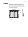
Fan Module
The 12000E fan module is installed horizontally above the interface module
slots. It comes pre-installed and should not be removed unless it is being
replaced. Fan functionality is indicated by a FAN LED on the management
module (all models): no illumination or solid green illumination indicates all
fans are currently functioning, solid amber illumination indicates one or more
of the four fans are no longer functioning.
Management
Module
12000E Front View
1
2
3
4
5
6
7
8
12000E
9 10 11 12 U1 U2
MULTIPLEXER
UPLINK
MODULE
PWR
FAN
PWR
Lnk
Act
Dplx
Fan
Module
Fan
LED
MULTIPLEXER
UPLINK
MODULE
PWR
FAN
Lnk
Act
Dplx
TIM
MUM
05-17820
CAUTION:
Do not operate the 12000E without a fan module or with a fan module
that is not functioning properly.
IPD1-A2-ZZ40-20
12000E IP Broadband Loop Carrier Installation Instructions
19
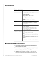
Specifications
Table 2:
Specifications
Specification
Criteria
Environment
Operating Temperature:
–40° F to 149° F (–40° C to 65° C)
Storage Temperature:
–40° F to 158° F (–40° C to 70° C)
Humidity:
5 % to 95 %, non-condensing
Altitude:
–200 ft to 16,500 ft (–60 m to 5,000 m)
Physical
15.75" High x 17" Wide x 18" Deep
(40 cm High x 43.2 cm Wide x 46 cm Deep)
47 lbs (21.4 kg)
Power
–48 VDC
30 amps maximum
Although actual power draw depends upon
chassis configuration, a fully loaded chassis
averages around 15 amps.
Regulatory Compliance NEBS:
GR-63-CORE; GR-1089-CORE
EMC:
FCC Part 15; CSA/C108.8; EN55022; EN55024
Safety:
CSA 22.2 No. 60950-1-03; EN60950-1:2001; CE
Marking
Telecom:
ACTA968 (Part 68); ICCS-03; TBR12; TBR13
!
Important Safety Instructions
1 Read and follow all warning notices and instructions marked on the
product or included in the manual.
2 Do not attempt to service this product yourself, as opening or removing
covers may expose you to dangerous high voltage points or other risks.
Refer all servicing to qualified service personnel.
3 WARNING: This unit supports a redundant 48 VDC power input
connection. Disconnect both sources of input power before servicing.
20
12000E IP Broadband Loop Carrier Installation Instructions
IPD1-A2-ZZ40-20
Important Safety Instructions
4 This product is to be installed only in a Restricted Access Location
(dedicated equipment rooms, equipment closets or the like) in accordance
with articles 110-16, 110-17 and 110-18 of the National Electrical Code,
ANSI/NFPA 70.
5 This product is to be connected to a 48 VDC SELV supply source that is
electrically isolated from the AC source.
6 The positive terminal of the 48 VDC source is to be reliably connected to
earth. Connect a green/yellow earthing (grounding) wire to the protective
earthing (grounding) lug connector, identified by the protective earth
symbol on the chassis.
7 A readily accessible disconnect device as part of the building installation
shall be incorporated in fixed wiring. The disconnect device (a 48 VDC,
30 A, single pole circuit breaker or switch) must be included in the
ungrounded supply conductor. Over current protection must be included
with a 48 VDC, 30 A fuse or circuit breaker in the ungrounded conductor.
Use minimum 8 AWG (6 mm2) fixed power source wires with strain
retention.
8 Do not allow anything to rest on the power cord and do not locate the
product where persons will walk on the power cord.
9 Slots and openings in the cabinet are provided for ventilation. To ensure
reliable operation of the product and to protect it from overheating, these
slots and openings must not be blocked or covered.
10 General purpose cables are described for use with this product. Special
cables, which may be required by the regulatory inspection authority for
the installation site, are the responsibility of the customer. To reduce the
risk of fire, use a UL Listed or CSA Certified, minimum 26 AWG (0.128
mm2) telecommunication cable, or comparable cables certified for use in
the country of installation.
11 A rare phenomenon can create a voltage potential between the earth
grounds of two or more buildings. If products installed in separate
buildings are interconnected, the voltage potential may cause a hazardous
condition. Consult a qualified electrical consultant to determine whether
or not this phenomenon exists and, if necessary, implement corrective
action prior to interconnecting the products.
12 In addition, if the equipment is to be used with telecommunications
circuits, take the following precautions:
— Never install telephone wiring during a lightning storm.
— Never install telephone jacks in wet locations unless the jack is
specifically designed for wet locations.
— Never touch uninsulated telephone wires or terminals unless the
telephone line has been disconnected at the network interface.
— Use caution when installing or modifying telephone lines.
— Avoid using a telephone (other than a cordless type) during an
electrical storm. There may be a remote risk of electric shock from
lightning.
IPD1-A2-ZZ40-20
12000E IP Broadband Loop Carrier Installation Instructions
21
— Do not use the telephone to report a gas leak in the vicinity of the
leak.
13 The equipment is intended for installation in an environment that is free
of dust and dirt.
14 When installed in the final configuration, the product must comply with
the applicable Safety Standards and regulatory requirements of the
country in which it is installed. If necessary, consult with the appropriate
regulatory agencies and inspection authorities to ensure compliance.
15 CLASS 1 LASER PRODUCT: This product has provisions for the
customer to install a Class 1 laser transceiver, which provides optical
coupling to the telecommunication network. Once a Class 1 laser product
is installed, the equipment is to be considered to be a Class 1 Laser
Product (Appareil à Laser de Classe 1). The customer is responsible for
selecting and installing the laser transceiver and for insuring that the Class
1 AEL (Allowable Emission Limit) per EN/IEC 60825 is not exceeded
after the laser transponders have been installed. Do not install laser
products whose class rating is greater than 1. Refer to all important safety
instructions that accompanied the transceiver prior to installation. Only
laser Class 1 devices certified for use in the country of installation by the
cognizant agency are to be utilized in this product. Also, laser warnings
are to be provided in accordance with IEC 60825-1 and its Amendments 1
and 2, as well as 21 CFR 1010 and 1040.10(g).
EMI Notices
This equipment has been tested and found to comply with the limits
for a Class A digital device, pursuant to Part 15 of the FCC rules.
These limits are designed to provide reasonable protection against
harmful interference when the equipment is operated in a
commercial environment. This equipment generates, uses, and can
radiate radio frequency energy and, if not installed and used in
accordance with the instruction manual, may cause harmful
interference to radio communications. Operation of this equipment in
a residential area is likely to cause harmful interference in which case
the user will be required to correct the interference at his own
expense.
The authority to operate this equipment is conditioned by the
requirements that no modifications will be made to the equipment
unless the changes or modifications are expressly approved by Zhone
Technologies, Inc.
This Class A digital apparatus meets all requirements of the
Canadian interference-causing equipment regulations.
Cet appareil numérique de la classe A respecte toutes les exigences du
règlement sur le matérial brouilleur du Canada.
22
12000E IP Broadband Loop Carrier Installation Instructions
IPD1-A2-ZZ40-20
Notice to Users of the Canadian Telephone Network
Notice to Users of the Canadian Telephone Network
NOTICE: This equipment meets the applicable Industry Canada Terminal
Equipment Technical Specifications. This is confirmed by the registration
number. The abbreviation IC before the registration number signifies that
registration was performed based on a Declaration of Conformity indicating
that Industry Canada technical specifications were met. It does not imply that
Industry Canada approved the equipment.
NOTICE: The Ringer Equivalence Number (REN) for this terminal
equipment is labeled on the equipment. The REN assigned to each terminal
equipment provides an indication of the maximum number of terminals
allowed to be connected to a telephone interface. The termination on an
interface may consist of any combination of devices subject only to the
requirement that the sum of the Ringer Equivalence Numbers of all the
devices does not exceed five.
If your equipment is in need of repair, contact your local sales representative,
service representative, or distributor directly.
CE Marking
When the product is marked with the CE mark on the equipment label, a
supporting Declaration of Conformity may be downloaded from the Zhone
World Wide Web site at www.zhone.com.
Product Documentation Online
Complete documentation for this product is available at www.zhone.com.
Contacting Global Service and Support
Contact Global Service and Support (GSS) if you have any questions about
this or other Zhone products. Before contacting GSS, make sure you have the
following information:
IPD1-A2-ZZ40-20
z
Zhone product you are using
z
System configuration
z
Software version running on the system
z
Description of the issue
12000E IP Broadband Loop Carrier Installation Instructions
23
Technical Support
If you require assistance with the installation or operation of your product, or
if you want to return a product for repair under warranty, contact GSS. The
contact information is as follows:
E-mail
[email protected]
Telephone (North America)
877-ZHONE20
Telephone (International)
510-777-7133
Internet
www.zhone.com/support
If you purchased the product from an authorized dealer, distributor, Value
Added Reseller (VAR), or third party, contact that supplier for technical
assistance and warranty support.
Service Requirements
If the product malfunctions, all repairs must be performed by the
manufacturer or a Zhone-authorized agent. It is the responsibility of users
requiring service to report the need for service to GSS.
*IPD1-A2-ZZ40-20*
*IPD1-A2-ZZ40-20*
24
12000E IP Broadband Loop Carrier Installation Instructions
IPD1-A2-ZZ40-20