1
AlphaServer ES45
Owner's Guide
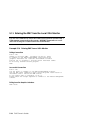
Order Number: EK-ES450-UG. B01
This manual is for managers and operators of ES45 systems.
Compaq Computer Corporation
First Printing, Februrary 2002
© 2002 Compaq Computer Corporation
Compaq, the Compaq logo, Compaq Insight Manager, AlphaServer, StorageWorks, and TruCluster
Registered in U.S. Patent and Trademark Office. OpenVMS and Tru64 are trademarks of Compaq
Information Technologies Group, L.P. in the United States and other countries.
Linux is a registered trademark of Linus Torvalds in several countries. UNIX is a trademark of The
Open Group in the United States and other countries. All other product names mentioned herein may
be trademarks of their respective companies.
Compaq shall not be liable for technical or editorial errors or omissions contained herein. The
information in this document is provided “as is” without warranty of any kind and is subject to change
without notice. The warranties for Compaq products are set forth in the express limited warranty
statements accompanying such products. Nothing herein should be construed as constituting an
additional warranty.
FCC Notice
This equipment generates, uses, and may emit radio frequency energy. The equipment has been type
tested and found to comply with the limits for a Class A digital device pursuant to Part 15 of FCC
rules, which are designed to provide reasonable protection against such radio frequency interference.
Operation of this equipment in a residential area may cause interference in which case the user at his
own expense will be required to take whatever measures may be required to correct the interference.
Any modifications to this device—unless expressly approved by the manufacturer—can void the user’s
authority to operate this equipment under part 15 of the FCC rules.
Modifications
The FCC requires the user to be notified that any changes or modifications made to this device that are
not expressly approved by Compaq Computer Corporation may void the user's authority to operate the
equipment.
Cables
Connections to this device must be made with shielded cables with metallic RFI/EMI connector hoods
in order to maintain compliance with FCC Rules and Regulations.
Taiwanese Notice
Japanese Notice
Canadian Notice
This Class A digital apparatus meets all requirements of the Canadian Interference-Causing Equipment
Regulations.
Avis Canadien
Cet appareil numérique de la classe A respecte toutes les exigences du Règlement sur le matériel
brouilleur du Canada.
European Union Notice
Products with the CE Marking comply with both the EMC Directive (89/336/EEC) and the Low
Voltage Directive (73/23/EEC) issued by the Commission of the European Community.
Compliance with these directives implies conformity to the following European Norms (in brackets
are the equivalent international standards):
EN55022:1998 (CISPR 22) - Electromagnetic Interference
EN55024:1998 (CISPR 24) - Electromagnetic Immunity
EN60950:2000 (IEC950) - Product Safety
EN61000-3-2:1995 – Harmonic Current Emissions
EN61000-3-3:1995 – Voltage Fluctuations Flicker
Warning!
This is a Class A product. In a domestic environment this product may cause radio interference in
which case the user may be required to take adequate measures.
Achtung!
Dieses ist ein Gerät der Funkstörgrenzwertklasse A. In Wohnbereichen können bei Betrieb dieses
Gerätes Rundfunkstörungen auftreten, in welchen Fällen der Benutzer für entsprechende
Gegenmaßnahmen verantwortlich ist.
Shielded Cables
If shielded cables have been supplied or specified, they must be used on the system in order to
maintain international regulatory.
Contents
Preface ....................................................................................................................... xv
Chapter 1
1.1
1.2
1.3
1.4
1.5
1.6
1.7
1.8
1.7.1
1.7.2
1.7.3
1.9
1.10
1.11
1.12
1.13
Model Differences.................................................................................. 1-2
System Enclosures................................................................................. 1-3
System Chassis—Front View/Top View................................................ 1-5
System Chassis—Rear View ................................................................. 1-7
Rear Ports and Slots ............................................................................. 1-8
Operator Control Panel....................................................................... 1-10
System Motherboard........................................................................... 1-12
I/O Backplane...................................................................................... 1-14
Model 1B ............................................................................................. 1-14
Model 2B ............................................................................................. 1-16
Model 3B ............................................................................................ 1-18
Power Supplies.................................................................................... 1-20
Removable Media Storage................................................................... 1-22
Storage Subsystem.............................................................................. 1-23
System Access ..................................................................................... 1-24
Console Terminal ................................................................................ 1-26
Chapter 2
2.1
2.2
2.2.1
2.2.2
2.3
2.3.1
2.3.2
2.4
2.4.1
System Overview
Operation
Powering Up the System....................................................................... 2-2
Power-Up Displays................................................................................ 2-3
SROM Power-Up Display...................................................................... 2-4
SRM Console Power-Up Display........................................................... 2-6
SRM Console ....................................................................................... 2-10
Selecting the Display Device............................................................... 2-11
Setting a Control Panel Message ........................................................ 2-12
Displaying the Hardware Configuration ............................................ 2-13
Displaying Boot Environment Variables ............................................ 2-14
v
2.4.2
2.4.3
2.4.4
2.5
2.6
2.6.1
2.6.2
2.6.3
2.6.4
2.7
2.7.1
2.7.2
2.7.3
2.7.4
2.7.5
Displaying the Logical Hardware Configuration................................ 2-16
Displaying the Bootable Devices......................................................... 2-22
Viewing the Memory Configuration.................................................... 2-24
Setting SRM Environment Variables ................................................. 2-25
Setting Console Security ..................................................................... 2-26
Setting the Console Password............................................................. 2-27
Setting the Console to Secure Mode.................................................... 2-29
Turning Off Security During a Console Session ................................. 2-30
Returning to User Mode...................................................................... 2-32
Updating Firmware ............................................................................ 2-33
Firmware Update Utility .................................................................... 2-34
Manual Updates.................................................................................. 2-36
Updating from the CD-ROM............................................................... 2-37
Updating from an OpenVMS System Disk ......................................... 2-38
Updating from the Network................................................................ 2-39
Chapter 3
3.1
3.1.1
3.1.2
3.1.3
3.1.4
3.1.5
3.1.6
3.2
3.2.1
3.3
3.4
3.5
3.5.1
3.6
Setting Boot Options ............................................................................. 3-2
auto_action............................................................................................ 3-3
bootdef_dev............................................................................................ 3-4
boot_file ................................................................................................. 3-5
boot_osflags ........................................................................................... 3-6
ei*0_inet_init or ew*0_inet_init............................................................ 3-9
ei*0_protocols or ew*0_protocols......................................................... 3-11
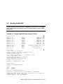
Booting Tru64 UNIX........................................................................... 3-13
Booting Tru64 UNIX over the Network.............................................. 3-15
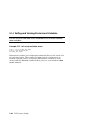
Starting a Tru64 UNIX Installation ................................................... 3-17
Booting Linux...................................................................................... 3-19
Booting OpenVMS............................................................................... 3-22
Booting OpenVMS from the InfoServer .............................................. 3-24
Starting an OpenVMS Installation..................................................... 3-26
Chapter 4
4.1
4.2
4.3
4.4
4.5
4.6
4.7
vi
Booting and Installing an Operating System
Configuring and Installing Components
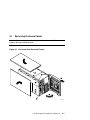
Removing Enclosure Panels.................................................................. 4-3
Removing Covers from the System Chassis.......................................... 4-7
Before Installing Components............................................................. 4-11
Memory Allocation .............................................................................. 4-12
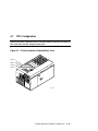
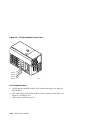
Power Supply Configuration ............................................................... 4-15
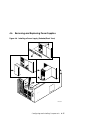
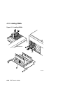
Removing and Replacing Power Supplies........................................... 4-17
CPU Configuration.............................................................................. 4-19
4.8
4.9
4.10
4.11
4.11.1
4.11.2
4.11.3
4.12
4.13
4.13.1
4.14
4.15
4.15.1
4.16
Installing CPUs................................................................................... 4-21
Memory Configuration ........................................................................ 4-23
Installing DIMMs................................................................................ 4-28
PCI Configuration ............................................................................... 4-31
Model 1B PCI Backplane .................................................................... 4-32
Model 2B PCI Backplane .................................................................... 4-33
Model 3B PCI Backplane .................................................................... 4-34
Installing PCI Cards ........................................................................... 4-35
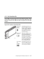
Installing Universal Hard Disk Drives............................................... 4-38
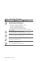
Disk Drive Status LEDs ............................................................... 4-41
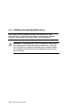
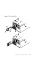
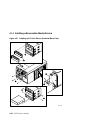
Installing a Removable Media Device................................................. 4-44
Installing Disk Drive Cages................................................................ 4-47
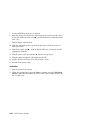
Cabling a Second Disk Drive Cage ............................................... 4-52
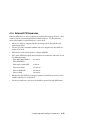
External SCSI Expansion ................................................................... 4-53
Chapter 5
5.1
5.2
5.3
5.4
5.5
5.5.1
5.5.2
5.5.3
5.5.4
5.5.5
5.5.6
5.5.7
5.5.8
5.6
5.7
5.8
5.9
5.10
5.11
5.12
5.13
5.14
5.14.1
5.14.2
Firmware
Console Overview.................................................................................. 5-2
Invoking the SRM Console.................................................................... 5-3
SRM Command Overview ..................................................................... 5-4
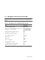
Management Tasks Performed from SRM............................................ 5-9
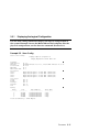
Getting Help on SRM Commands....................................................... 5-10
Displaying the Logical Configuration ................................................. 5-11
Displaying the Bootable Devices......................................................... 5-16
Displaying the System FRUs .............................................................. 5-17
Displaying FRUs with Errors ............................................................. 5-20
Displaying the Memory Configuration ............................................... 5-21
Displaying the PAL Version................................................................ 5-21
Displaying the Power Status............................................................... 5-22
Displaying the SRM Console Version ................................................. 5-23
Booting an Operating System ............................................................. 5-24
Testing the System ............................................................................. 5-26
Forcing a System Crash Dump ........................................................... 5-28
Resuming Program Execution ............................................................ 5-30
Reading a File ..................................................................................... 5-31
Initializing the System........................................................................ 5-32
Creating a Power-Up Script................................................................ 5-35
Entering the RMC from the Local VGA Monitor ................................ 5-37
Setting and Viewing Environment Variables ..................................... 5-39
auto_action.................................................................................... 5-43
bootdef_dev ................................................................................... 5-45
vii
5.14.3
5.14.4
5.14.5
5.14.6
5.14.7
5.14.8
5.14.9
5.14.10
5.14.11
5.14.12
5.14.13
5.14.14
5.14.15
5.14.16
5.14.17
5.14.18
5.14.19
5.14.20
5.14.21
5.14.22
5.14.23
boot_file......................................................................................... 5-46
boot_osflags................................................................................... 5-47
com*_baud .................................................................................... 5-51
com*_flow...................................................................................... 5-52
com1_mode.................................................................................... 5-53
com*_modem................................................................................. 5-55
console........................................................................................... 5-56
cpu_enabled .................................................................................. 5-57
ei*0_inet_init or ew*0_inet_init.................................................... 5-59
ei*0_mode or ew*0_mode.............................................................. 5-60
ei*0_protocols or ew*0_protocols................................................... 5-61
kbd_hardware_type ...................................................................... 5-62
language........................................................................................ 5-63
memory_test ................................................................................. 5-64
ocp_text ......................................................................................... 5-65
os_type .......................................................................................... 5-66
pci_parity ...................................................................................... 5-67
pk*0_fast....................................................................................... 5-68
pk*0_host_id ................................................................................. 5-69
pk*0_soft_term.............................................................................. 5-70
tt_allow_login................................................................................ 5-72
Chapter 6
6.1
6.2
6.2.1
6.3
6.4
6.5
6.6
6.6.1
6.6.2
6.6.3
6.6.4
6.6.5
6.7
6.8
6.9
viii
Remote Management
RMC Overview ...................................................................................... 6-2
Operating Modes................................................................................... 6-4
Bypass Modes........................................................................................ 6-6
Terminal Setup ..................................................................................... 6-9
SRM Environment Variables for COM1 ............................................. 6-10
Entering the RMC............................................................................... 6-11
Using the Command-Line Interface.................................................... 6-13
Displaying the System Status............................................................. 6-14
Displaying the System Environment.................................................. 6-16
Using Power On and Off, Reset, and Halt Functions ......................... 6-18
Configuring Remote Dial-In................................................................ 6-20
Configuring Dial-Out Alert ................................................................. 6-22
Resetting the RMC to Factory Defaults.............................................. 6-25
RMC Command Reference .................................................................. 6-27
Troubleshooting Tips .......................................................................... 6-39
Chapter 7
7.1
7.1.1
7.1.2
7.1.3
7.2
7.3
7.4
7.4.1
7.4.2
7.4.3
7.4.4
7.4.5
7.4.6
7.4.7
7.5
7.6
Power-Up Error Messages .................................................................... 7-2
Messages with Beep Codes ................................................................... 7-2
Checksum Error .................................................................................... 7-4
No MEM Error ...................................................................................... 7-6
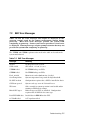
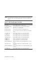
RMC Error Messages ............................................................................ 7-7
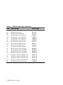
SROM Error Messages.......................................................................... 7-9
SRM Diagnostics................................................................................. 7-11
Console Event Log............................................................................... 7-11
Show Device Command....................................................................... 7-12
Test Command .................................................................................... 7-12
Show FRU Command.......................................................................... 7-14
Show Error Command......................................................................... 7-16
Show Power Command ....................................................................... 7-17
Crash Command ................................................................................. 7-18
Troubleshooting Tables....................................................................... 7-19
Option Card Problems......................................................................... 7-25
Chapter 8
8.1
8.2
8.3
8.4
8.5
Troubleshooting
Specifications
Physical Specifications.......................................................................... 8-2
Environmental Specifications ............................................................... 8-6
Electrical Specifications........................................................................ 8-7
Regulatory Approvals............................................................................ 8-9
Acoustic Data ...................................................................................... 8-10
Index
Examples
2–1
2–2
2–3
2–4
2–5
2–6
2–7
2–8
Sample SROM Power-Up Display......................................................... 2-4
SRM Power-Up Display ........................................................................ 2-6
SRM Console Example........................................................................ 2-10
Set Ocp_Text Command...................................................................... 2-12
Show Boot*.......................................................................................... 2-14
Show Config ........................................................................................ 2-16
Show Device ........................................................................................ 2-22
Show Memory...................................................................................... 2-24
ix
2–9
2–10
2–11
2–12
2–13
3–1
3–2
3–3
3–4
3–5
3–6
3–7
4–1
5–1
5–2
5–3
5–4
5–5
5–6
5–7
5–8
5–9
5–10
5–11
5–12
5–13
5–14
5–15
5–16
5–17
5–18
5–19
6–1
6–2
7–1
7–2
7–3
7–4
7–5
7–6
7–7
x
Set Password....................................................................................... 2-27
Set Secure ........................................................................................... 2-29
Login ................................................................................................... 2-30
Clear Password ................................................................................... 2-32
Update Utility Display........................................................................ 2-34
Booting Tru64 UNIX from a Local SCSI Disk .................................... 3-13
RIS Boot .............................................................................................. 3-15
Text-Based Installation Display ......................................................... 3-17
Linux Boot Output .............................................................................. 3-20
Booting OpenVMS from the Local CD-ROM Drive............................. 3-22
InfoServer Boot ................................................................................... 3-24
OpenVMS Installation Menu .............................................................. 3-26
Memory Allocation Crash/Reboot Cycle.............................................. 4-12
Help (or Man)...................................................................................... 5-10
Show Config ........................................................................................ 5-11
Show Device ........................................................................................ 5-16
Show Fru............................................................................................. 5-17
Show Error .......................................................................................... 5-20
Show Memory...................................................................................... 5-21
Show PAL............................................................................................ 5-21
Show Power......................................................................................... 5-22
Show Version ...................................................................................... 5-23
OpenVMS Boot.................................................................................... 5-24
Test...................................................................................................... 5-26
Crash................................................................................................... 5-28
Continue.............................................................................................. 5-30
More .................................................................................................... 5-31
Init....................................................................................................... 5-32
Editing the Nvram Script ................................................................... 5-35
Clearing the Nvram Script.................................................................. 5-35
Entering RMC from a VGA Monitor ................................................... 5-37
Set envar and Show envar................................................................... 5-39
Dial-In Configuration.......................................................................... 6-20
Dial-Out Alert Configuration.............................................................. 6-22
Checksum Error and Fail-Safe Load .................................................... 7-4
No MEM Error ...................................................................................... 7-6
Sample Console Event Log.................................................................. 7-11
Show Device Command....................................................................... 7-12
Test Command .................................................................................... 7-12
Show Fru Command ........................................................................... 7-14
Show Error Command......................................................................... 7-16
7–8
7–9
Show Power Command ....................................................................... 7-17
Crash Command ................................................................................. 7-18
Figures
1–1
1–2
1–3
1–4
1–5
1–6
1–7
1–8
1–9
1–10
1–11
1–12
1–13
1–14
2–1
4–1
4–2
4–3
4–4
4–5
4–6
4–7
4–8
4–9
4–10
4–11
4–12
4–13
4–14
4–15
4–16
4–17
4–18
4–19
4–20
ES45 Systems........................................................................................ 1-3
Top/Front Components (Pedestal) ........................................................ 1-5
Rear Components (Pedestal)................................................................. 1-7
Rear Connectors.................................................................................... 1-8
Operator Control Panel....................................................................... 1-10
System Motherboard Block Diagram.................................................. 1-12
Location of I/O Slots: Model 1B........................................................... 1-14
Location of I/O Slots: Model 2B .......................................................... 1-16
Location of I/O Slots: Model 3B .......................................................... 1-18
Power Supplies.................................................................................... 1-20
Removable Media Drive Area ............................................................. 1-22
Storage Cages...................................................................................... 1-23
System Keys........................................................................................ 1-24
Console Terminal Connections ........................................................... 1-26
Operator Control Panel......................................................................... 2-2
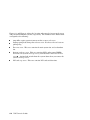
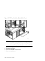
Enclosure Panel Removal (Tower) ........................................................ 4-3
Enclosure Panel Removal (Pedestal) .................................................... 4-5
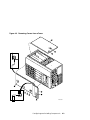
Removing Covers from a Tower ............................................................ 4-9
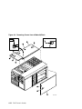
Removing Covers from a Pedestal/Rack ............................................. 4-10
Power Supply Locations...................................................................... 4-15
Installing a Power Supply (Pedestal/Rack View)................................ 4-17
CPU Slot Locations (Pedestal/Rack View) .......................................... 4-19
CPU Slot Locations (Tower View)....................................................... 4-20
CPU Card Installation (Pedestal/Rack View) ..................................... 4-21
Stacked and Unstacked DIMMs ......................................................... 4-24
Memory Configuration (Pedestal/Rack View)..................................... 4-26
Memory Configuration (Tower View).................................................. 4-27
Installing DIMMs................................................................................ 4-28
Aligning DIMM in MMB..................................................................... 4-30
Model 1B Backplane .......................................................................... 4-32
Model 2B Backplane .......................................................................... 4-33
Model 3B Backplane .......................................................................... 4-34
PCI Card Installation (Pedestal/Rack View)....................................... 4-36
Installing a Hard Drive....................................................................... 4-39
Location of Drive Status LEDs .......................................................... 4-41
xi
4–21
4–22
4–23
4–24
4–25
6–1
6–2
6–3
6–4
xii
Installing a 5.25-Inch Device (Pedestal/Rack View) ........................... 4-44
Disk Cage Installation ........................................................................ 4-47
Disk Cage Installation (Continued) .................................................... 4-49
Fan Locations...................................................................................... 4-51
Cabling a Second Disk Cage ............................................................... 4-52
Data Flow in Through Mode ................................................................. 6-4
Data Flow in Bypass Mode ................................................................... 6-6
Setup for RMC (Tower View) ............................................................... 6-9
RMC Jumpers (Default Positions) ...................................................... 6-26
Tables
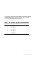
1–1
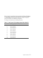
1–2
1–3
1–4
2–1
2–2
2–3
2–4
3–1
4–1
5–1
5–2
5–3
5–4
5–5
5–6
5–7
5–8
5–9
6–1
6–2
6–3
7–1
7–2
7–3
7–4
7–5
7–6
7–7
7–8
7–9
7–10
8–1
8–2
8–3
8–4
8–5
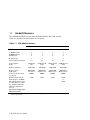
ES45 Model Summary .......................................................................... 1-2
How Physical I/O Slots Map to Logical Slots: Model 1B..................... 1-15
How Physical I/O Slots Map to Logical Slots: Model 2B .................... 1-17
How Physical I/O Slots Map to Logical Slots: Model 3B..................... 1-19
Physical I/O Slots Map to Logical Slots: Model 1B ............................. 2-20
Physical I/O Slots Map to Logical Slots: Model 2B ............................. 2-20
Physical I/O Slots Map to Logical Slots: Model 3B ............................. 2-21
Device Naming Conventions ............................................................... 2-23
OpenVMS Boot Flag Settings ............................................................... 3-9
Disk Drive Status LED Conditions..................................................... 4-40
Summary of SRM Console Commands ................................................. 5-4
Notation Formats for SRM Console Commands ................................... 5-6
Special Characters for SRM Console .................................................... 5-7
Management Tasks and Related SRM Commands............................... 5-9
How Physical I/O Slots Map to Logical Slots ...................................... 5-15
Device Naming Conventions ............................................................... 5-16
Bit Assignments for Error Field ......................................................... 5-19
Environment Variable Summary........................................................ 5-41
OpenVMS Boot Flag Settings ............................................................. 5-49
Status Command Fields...................................................................... 6-15
Elements of Dial String and Alert String ........................................... 6-24
RMC Troubleshooting ......................................................................... 6-39
Error Beep Codes .................................................................................. 7-3
RMC Error Messages ............................................................................ 7-7
SROM Error Messages.......................................................................... 7-9
Bit Assignments for Error Field ......................................................... 7-16
Power Problems................................................................................... 7-20
Problems Getting to Console Mode ..................................................... 7-21
Problems Reported by the Console...................................................... 7-22
Boot Problems ..................................................................................... 7-23
Errors Reported by the Operating System ......................................... 7-24
Troubleshooting PCI Bus Problems .................................................... 7-26
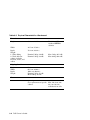
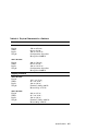
Physical Characteristics — Tower ........................................................ 8-2
Physical Characteristics — Pedestal .................................................... 8-3
Physical Characteristics — Rackmount................................................ 8-4
Physical Characteristics — Cabinets.................................................... 8-5
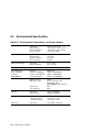
Environmental Characteristics — All System Variants....................... 8-6
xiii
8–6
8–7
8–8
xiv
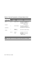
Electrical Characteristics — All System Variants................................ 8-7
Regulatory Approvals............................................................................ 8-9
Acoustic Data ...................................................................................... 8-10
Preface
Intended Audience
This manual is for managers and operators of AlphaServer ES45 systems.
Document Structure
This manual uses a structured documentation design. Topics are organized into
small sections, usually consisting of two facing pages. Most topics begin with an
abstract that provides an overview of the section, followed by an illustration or
example. The facing page contains descriptions, procedures, and syntax
definitions.
This manual has eight chapters.
•
Chapter 1, System Overview, gives an overview of the system and
describes the components.
•
Chapter 2, Operation, gives basic operating instructions on powering up
and configuring the machine, setting console security, and updating
firmware.
•
Chapter 3, Booting and Installing an Operating System, describes
how to boot a supported operating system and how to begin an operating
system installation.
•
Chapter 4, Configuring and Installing Components, shows how to
install memory DIMMs, CPUs, PCI cards, and other options.
•
Chapter 5, Firmware, describes the SRM firmware, which allows you to
configure and boot the Tru64 UNIX, Linux, or OpenVMS operating system
and verify the configuration of devices. It also provides a reference to the
SRM commands and environment variables.
•
Chapter 6, Remote Management, describes the function and operation of
the integrated remote management console.
xv
•
Chapter 7, Troubleshooting, gives basic troubleshooting procedures.
•
Chapter 8, Specifications, gives system specifications.
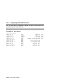
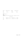
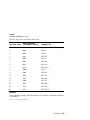
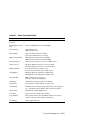
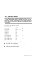
Documentation Titles
Table 1 ES45 Documentation
Title
Order Number
User Documentation Kit
Owner’s Guide
Documentation CD (6 languages)
QA-6NUAB-G8
EK–ES450–UG
AG–RPJ7A–TS
Maintenance Kit
Service Guide
Service Guide HTML CD (includes IPB)
QA–6NUAA–G8
EK–ES450–SV
AG–RPJ5A–TS
Loose Piece Items
Basic Installation Card
Rackmount Installation Guide
Rackmount Installation Template
EK–ES450–PD
EK–ES450–RG
EK–ES450–TP
Support Resources
Support resources for this system are available on the Internet, including a
supported options list, firmware updates, and patches.
http://www.compaq.com/alphaserver/es45/es45.html
xvi
Chapter 1
System Overview
This chapter provides an overview of the system, including:
•
System Enclosures
•
System Chassis—Front View/Top View
•
System Chassis—Rear View
•
Rear Ports and Slots
•
Operator Control Panel
•
System Motherboard
•
I/O Backplane
•
Power Supplies
•
Removable Media Storage
•
Storage Subsystem
•
System Access
•
Console Terminal
NOTE: See Chapter 4 for warnings and procedures for accessing internal parts
of the system.
System Overview 1-1
1.1
Model Differences
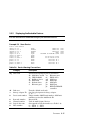
The AlphaServer ES45 has four different models (Models 1B, 2, 2B, and 3B).
Table 1–1 describes the model differences in detail.
Table 1–1 ES45 Model Summary
Model 2
Model 1B
Model 2B
Model 3B
I/O Slots
10
7
10
10
33 MHz PCI slots
66 MHz PCI slots
4X AGP slots
4
6
0
2
4
1
4
6
0
8
2
0
Hot-swap slots
7
4
7
7
2-3
1-3
1-3
1-3
Power supplies
Watts
H7906-A9
720
3X-H7514-AA
1080
3X-H7514-AA
1080
3X-H7514-AA
1080
Memory (min/max)
1GB-32GB
1GB-16GB
1GB-32GB
1GB-32GB
Memory option*
4 GB option
(Same for all other memory options)
MS620-DA
Low Power
DIMM
MS620-DB
Higher power
DIMM
MS620-DB
Higher power
DIMM
MS620-DB
Higher power
DIMM
Memory Channel maximum I/O space (CCMABAA) Setting must be same
for all members of cluster.
See Quickspecs Memory
Channel configuration
notes at:
128K
128K
128K
512K
or
128K
Power supplies (min/max)
http://www.compaq.com/
alphaserver/es45/
* For Models 1B, 2B, and 3B the 3X-H7514-AA power supply is required to meet additional DIMM
power requirements.
1-2 ES45 Owner’s Guide
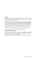
1.2
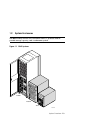
System Enclosures
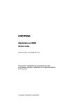
The ES45 family consists of a standalone tower, a pedestal with expanded storage capacity, and a rackmount system.
Figure 1–1 ES45 Systems
Cabinet
Pedestal
Tower
PK0212B
System Overview 1-3
Model Variants
ES45 systems are offered with the following four models:
•
Model 1B – Six PCI slots with four slots at 66 MHz, two slots at 33 MHz,
and one AGP 4x slot.
•
Model 2 – Ten PCI slots with six slots at 66 MHz and four slots at 33 MHz
•
Model 2B – Ten PCI slots with six slots at 66 MHz and four slots at 33
MHz.
•
Model 3B – Ten PCI slots with two at 66 MHz and eight slots at 33 MHz.
Common Components
The basic building block of the system is the chassis, which houses the following
common components:
•
Up to four CPUs, based on the EV68 Alpha chip
•
200-pin memory DIMMs (up to 32 for Models 2, 2B, and 3B and up to 16 for
Model 1B)
•
I/O board
•
Floppy diskette drive (3.5-inch, high density)
•
CD-ROM drive
•
Two half-height or one full-height removable media bays
•
Up to two storage disk cages that house up to six 1-inch universal drives per
cage
•
Up to three power supplies, offering N+1 power
•
A 25-pin parallel port, two 9-pin serial ports, mouse and keyboard ports,
and one MMJ connector for a local console terminal
•
An operator control panel with a 16-character back-lit display and a Power
button, Halt button, and Reset button
1-4 ES45 Owner’s Guide
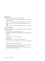
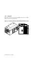
1.3
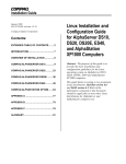
System Chassis—Front View/Top View
Figure 1–2 Top/Front Components (Pedestal)
8
7
6
4
1
9
3
6
2
5
PK0201B
System Overview 1-5
Operator control panel
CD-ROM drive
Removable media bays
Floppy diskette drive
Storage drive bays
Fans
CPUs
Memory
PCI cards
1-6 ES45 Owner’s Guide
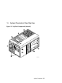
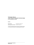
1.4
System Chassis—Rear View
Figure 1–3 Rear Components (Pedestal)
3
5
2
4
1
PK0206B
Power supplies
PCI bulkhead
I/O ports
Power harness access cover
Speaker
System Overview 1-7
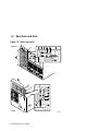
1.5
Rear Ports and Slots
Figure 1–4 Rear Connectors
Pedestal
1
2
3
4
5
6
8
7
8
1
2
3
4
5
7
Tower
1-8 ES45 Owner’s Guide
6
PK0209A
Rear Panel Connections
Modem port—Dedicated 9-pin port for modem connection to remote management console.
COM2 serial port—Extra port to modem or any serial device.
Keyboard port—To PS/2-compatible keyboard.
Mouse port—To PS/2-compatible mouse.
COM1 MMJ-type serial port/terminal port—For connecting a console terminal.
Parallel port—To parallel device such as a printer.
SCSI breakouts.
PCI slots—For option cards for high-performance network, video, disk controllers, and so forth.
System Overview 1-9
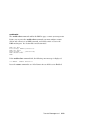
1.6
Operator Control Panel
The control panel provides system controls and status indicators. The
controls are the Power, Halt, and Reset buttons. A 16-character backlit alphanumeric display indicates system state. The panel has two
LEDs: a green Power OK indicator and an amber Halt indicator.
Figure 1–5 Operator Control Panel
1
2
3
4
5
6
PK0204
Control panel display. A one-line, 16-character alphanumeric display that
indicates system status during power-up and testing. During operation, the
control panel is back lit.
Power button. Powers the system on and off.
If a failure occurs that causes the system to shut down, pressing the power
button off and then on clears the shutdown condition and attempts to power
the system back on. Some conditions that prevent the system from powering on can be determined by entering the env command from the remote
management console (RMC). The RMC is powered separately from the rest
of the system and can operate as long as AC power is present. (See Chapter
6.)
1-10 ES45 Owner’s Guide
Power LED (green). Lights when the power button is pressed.
Reset button. A momentary contact switch that restarts the system and
reinitializes the console firmware. Power-up messages are displayed, and
then the console prompt is displayed or the operating system boot messages
are displayed, depending on how the startup sequence has been defined.
Halt LED (amber). Lights when you press the Halt button.
Halt button. Halts the system and returns to the SRM console.
If the Halt button is latched when the system is reset or powered up, the
system halts in the SRM console. Systems that are configured to autoboot
cannot boot until the Halt button is unlatched.
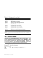
Commands issued from the remote management console (RMC) can be used to
reset, halt, and power the system on or off. For information on RMC, see Chapter 6.
RMC Command
Function
Power {off, on}
Equivalent to pressing the Power button on the system. If
the power button is in the Off position, the RMC Power On
command has no effect.
Halt {in, out}
Equivalent to pressing the Halt button on the control panel
to cause a halt (halt in) or releasing it from the latched position to de-assert the halt (halt out).
Reset
Equivalent to pressing the Reset button on the control panel.
System Overview 1-11
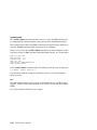
1.7
System Motherboard
The system motherboard is located on the floor of the system card cage
and has the majority of the logic for the system.
The system motherboard has connectors for the CPUs and memory motherboards (MMBs) and a connector to the I/O subsystem. Figure 1–6 shows the
location of these modules on the motherboard.
Figure 1–6 System Motherboard Block Diagram
Connector to PCI Backplane
J34
MMB3
J18
CPU2
J33
MMB2
J17
CPU0
J16
CPU1
J15
CPU3
J32
J31
MMB1
MMB0
Cterm
(VTerm_chk)
Vterm
(VTerm_data)
PK0323C
1-12 ES45 Owner’s Guide
CPU Card
The system can have up to four CPU cards. The CPU cards are installed on the
system board. Each CPU card contains an EV68 microprocessor, a current implementation of the Alpha architecture.
The microprocessor is a superscalar CPU with out-of-order execution and speculative execution to maximize speed and performance. It contains four integer
execution units and dedicated execution units for floating-point add, multiply,
and divide. It has an instruction cache and a data cache on the chip. Each
cache is a 64 KB, two-way, set-associative, virtually addressed cache that has
64-byte blocks. The data cache is a physically tagged, write-back cache.
Each CPU card has an 8 MB B-cache (backup cache) and a power regulator.
See Chapter 4 for instructions on installing additional CPUs.
Memory Motherboards (MMBs)
Memory options are installed into memory motherboards (MMBs) located on the
system motherboard (see Figure 1–6). There are four MMBs. The MMBs have
either four or eight slots for installing DIMMs.
See Chapter 4 for memory configuration rules and installation instructions.
System Overview 1-13
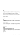
1.8
I/O Backplane
The ES45 server has three I/O versions: Models 1B, 2B, and 3B.
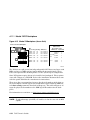
1.8.1
Model 1B
Model 1B has six PCI slots with four at 66 MHz, two at 33 MHz, and one AGP
4x slot.
Figure 1–7 Location of I/O Slots: Model 1B
1 2 3
4 5 6 7 8 9 10
MR0262A
1-14 ES45 Owner’s Guide
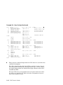
There is no direct correspondence between the physical numbers of the slots on
the I/O backplane and the logical slot identification reported with the SRM console show config command (described in Chapter 2). Table 1–2 maps the
physical slot numbers to the SRM logical ID numbers.
See Chapter 4 for instructions on installing PCI options.
Table 1–2 How Physical I/O Slots Map to Logical Slots: Model 1B
Physical Slot
SRM Logical ID (7-Slot PCI)
1
Hose 0 Slot ID 11
2
Hose 0 Slot ID 10
3
Hose 2 Slot ID 5
4
Hose 3 Slot ID 2
5
Hose 3 Slot ID 1
7
Hose 1 Slot ID 2
8
Hose 1 Slot ID 1
System Overview 1-15
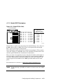
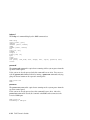
1.8.2
Model 2B
Model 2B has ten slots with six slots at 66 MHz and four slots at 33 MHz
(Model 2 uses the same configuration).
Figure 1–8 Location of I/O Slots: Model 2B (Pedestal/Rack View)
1 2 3
10-Slot
PCI
4 5 6 7 8 9 10
PK0226D
1-16 ES45 Owner’s Guide
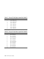
There is no direct correspondence between the physical numbers of the slots on
the I/O backplane and the logical slot identification reported with the SRM console show config command (described in Chapter 2). Table 1–3 maps the
physical slot numbers to the SRM logical ID numbers.
See Chapter 4 for instructions on installing PCI options.
Table 1–3 How Physical I/O Slots Map to Logical Slots: Model 2B
Physical Slot
SRM Logical ID (10-Slot PCI)
1
Hose 2 Slot ID 1
2
Hose 2 Slot ID 2
3
Hose 0 Slot ID 11
4
Hose 3 Slot ID 2
5
Hose 3 Slot ID 1
6
Hose 0 Slot ID 10
7
Hose 1 Slot ID 2
8
Hose 1 Slot ID 1
9
Hose 0 Slot ID 9
10
Hose 0 Slot ID 8
System Overview 1-17
1.8.3
Model 3B
The Model 3B has ten slots with eight at 33 MHz and two at 66 MHz.
Figure 1–9 Location of I/O Slots: Model 3B
1 2 3
10-Slot
PCI
4 5 6 7 8 9 10
MR0263
1-18 ES45 Owner’s Guide
There is no direct correspondence between the physical numbers of the slots on
the I/O backplane and the logical slot identification reported with the SRM console show config command (described in Chapter 2). Table 1–4 maps the
physical slot numbers to the SRM logical ID numbers.
See Chapter 4 for instructions on installing PCI options.
Table 1–4 How Physical I/O Slots Map to Logical Slots: Model 3B
Physical Slot
SRM Logical ID (10-Slot Legacy PCI)
1
Hose 2 Slot ID 1
2
Hose 2 Slot ID 2
3
Hose 0 Slot ID 11
4
Hose 3 Slot ID 2
5
Hose 3 Slot ID 1
6
Hose 0 Slot ID 10
7
Hose 1 Slot ID 2
8
Hose 1 Slot ID 1
9
Hose 0 Slot ID 9
10
Hose 0 Slot ID 8
System Overview 1-19
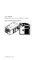
1.9
Power Supplies
The power supplies provide power to components in the system chassis. The number of power supplies required depends on the system
configuration.
Figure 1–10 Power Supplies
Tower
0
1
1
2
2
Pedestal/Rack
0
1
2
PK0207A
1-20 ES45 Owner’s Guide
One to three power supplies provide power to components in the system chassis.
The system supports redundant power configurations to ensure continued system operation if a power supply fails (The Model 2 has a minimum configuration of two power supplies).
The power supplies select line voltage and frequency are automatically selected
for 200–240 V and 50 Hz or 60 Hz.
Power Supply LEDs
Each power supply has two green LEDs that indicate the state of power to the
system.
POK (Power OK)
+5 V Auxiliary
Indicates that the power supply is functioning. The POK
LED is on when the system is running. When the system power is on and a POK LED is off, that supply is not
contributing to powering the system.
Indicates that AC power is flowing from the wall outlet.
As long as the power supply cord is plugged into the wall
outlet, the +5V Aux LED is always on, even when the
system power is off.
See Chapter 4 for instructions on installing additional power supplies.
System Overview 1-21
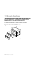
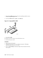
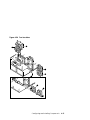
1.10 Removable Media Storage
The system chassis houses a CD-ROM drive
and a high-density 3.5inch floppy diskette drive
and supports two additional 5.25-inch
half-height devices or one additional full-height device.
See Chapter 4 for information on installing a removable media drive.
Figure 1–11 Removable Media Drive Area
2
1
PK0233
1-22 ES45 Owner’s Guide
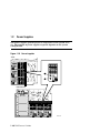
1.11 Storage Subsystem
The system chassis can house up to two universal storage disk cages.
The storage subsystem supports “hot pluggable" hard disk drives that
can be replaced while the storage backplane is powered and operating.
You can install up to six 1-inch universal hard drives in each storage disk cage.
See Chapter 4 for installation and swap procedures.
Figure 1–12 Storage Cages
MR0046A
System Overview 1-23
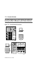
1.12 System Access
At the time of delivery, the system keys are taped inside the small front
door that provides access to the operator control panel and removable
media devices.
Figure 1–13 System Keys
Tower
Pedestal
1-24 ES45 Owner’s Guide
PK0224A
Both the tower and pedestal systems have a small front door through which
the control panel and removable media devices are accessible. At the time of
delivery, the system keys are taped inside this door.
The tower front door has a lock that lets you secure access to the disk drives
and to the rest of the system.
The pedestal has two front doors, both of which can be locked. The upper door
secures the disk drives and access to the rest of the system, and the lower door
secures the expanded storage.
NOTE: See Chapter 4 for warnings and procedures for accessing internal parts
of the system.
System Overview 1-25
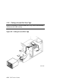
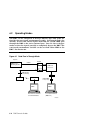
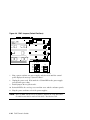
1.13 Console Terminal
The console terminal can be a serial (character cell) terminal connected to the COM1 or COM2 port or a VGA monitor connected to a
VGA adapter on PCI0. A VGA monitor requires a keyboard and mouse.
Figure 1–14 Console Terminal Connections
VT
Tower
VT
Pedestal/Rack
1-26 ES45 Owner’s Guide
PK0225B
Chapter 2
Operation
This chapter gives instructions for basic system operation. The following topics
are covered:
•
Powering Up the System
•
Power-Up Displays
•
SRM Console
•
Displaying the Hardware Configuration
•
Setting SRM Environment Variables
•
Setting Console Security
•
Updating Firmware
Operation
2-1
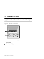
2.1
Powering Up the System
To power up the system, press the power button. Testing begins, and
status shows on the console terminal screen and in the control panel
display.
Figure 2–1 Operator Control Panel
2
1
PK0204A
2-2
Power button
Control panel display
ES45 Owner's Guide
2.2
Power-Up Displays
Power-up information is displayed on the operator control panel and
on the console terminal startup screen. Messages sent from the SROM
(serial read-only memory) program are displayed first, followed by
messages from the SRM console.
NOTE: The power-up text that is displayed on the screen depends on what kind
of terminal is connected as the console terminal: VT or VGA.
If the SRM console environment variable is set to serial, the entire
power-up display, consisting of the SROM and SRM power-up messages, is displayed on the VT terminal screen. If console is set to
graphics, no SROM messages are displayed, and the SRM messages
are delayed until VGA initialization has been completed.
•
Section 2.2.1 shows the SROM power-up messages and corresponding operator control panel (OCP) messages.
•
Section 2.2.2 shows the messages that are displayed once the SROM has
transferred control to the SRM console.
•
For a complete list of messages displayed on the OCP, see Chapter 7.
Operation
2-3
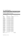
2.2.1
SROM Power-Up Display
Example 2–1 Sample SROM Power-Up Display
SROM V2.15 CPU # 00 @ 1000 MHz
SROM program starting
Reloading SROM
SROM V2.15 CPU # 00 @ 1000 MHz
System Bus Speed @ 0125 MHz
SROM program starting
PCI66 bus speed check
Reloading SROM
SROM V2.15 CPU # 00 @ 1000 MHz
System Bus Speed @ 0125 MHz
SROM program starting
PCI66 bus speed check
Starting secondary on CPU #1
Starting secondary on CPU #2
Starting secondary on CPU #3
Bcache data tests in progress
Bcache address test in progress
CPU parity and ECC detection in progress
Bcache ECC data tests in progress
Bcache TAG lines tests in progress
Memory sizing in progress
Memory configuration in progress
Testing AAR3
Memory data test in progress
Memory address test in progress
Memory pattern test in progress
Testing AAR2
Memory data test in progress
Memory address test in progress
Memory pattern test in progress
Testing AAR1
Memory data test in progress
Memory address test in progress
Memory pattern test in progress
Testing AAR0
Memory data test in progress
Memory address test in progress
Memory pattern test in progress
Memory thrashing test in progress
Memory initialization
Loading console
Code execution complete (transfer control)
2-4
ES45 Owner's Guide
RelCPU
BC Data
PCI Test
Power on
Size Mem
Load ROM
Jump to
Console
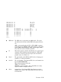
When the system powers up, the SROM code is loaded into the I-cache (instruction cache) on the first available CPU, which becomes the primary CPU.
The order of precedence is CPU0, CPU1, and so on. The primary CPU attempts to access the PCI bus. If it cannot, either a hang or a failure occurs,
and this is the only message displayed.
The primary CPU interrogates the I2C EEROM on the system board and CPU
modules through shared RAM. The primary CPU determines the CPU and
system configuration to jump to.
The primary CPU next checks the SROM checksum to determine the validity
of the flash SROM sectors.
If flash SROM is invalid, the primary CPU reports the error and continues the
execution of the SROM code. Invalid flash SROM must be reprogrammed.
If flash SROM is good, the primary CPU programs appropriate registers with
the values from the flash data and selects itself as the target CPU to be
loaded.
The primary CPU (usually CPU0) initializes and tests the B-cache and memory, then loads the flash SROM code to the next CPU. That CPU then initializes the EV68 chip) and marks itself as the secondary CPU. Once the primary
CPU sees the secondary, it loads the flash SROM code to the next CPU until
all remaining CPUs are loaded.
The flash SROM performs B-cache tests. For example, the ECC data test verifies the detection logic for single- and double-bit errors.
The primary CPU initiates all memory tests. The memory is tested for address and data errors for the first 32 MB of memory in each array. It also initializes all the “sized” memory in the system.
If a memory failure occurs, an error is reported. An untested memory array is
assigned to address 0 and the failed memory array is de-assigned. The memory tests are rerun on the first 32 MB of memory in each of the remaining arrays. If all memory fails, the “No Memory Available” message is reported and
the system halts.
If all memory passes, the primary CPU loads the console and transfers control
to it.
Operation
2-5
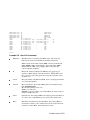
2.2.2
SRM Console Power-Up Display
At the completion of SROM power-up, the primary CPU transfers control to the SRM console program, described in Section 2.3. The console
program continues the system initialization. Failures are reported to
the console terminal through the power-up screen and a console event
log.
Example 2–2 SRM Power-Up Display
OpenVMS PALcode V1.88-28, Tru64 UNIX PALcode V1.83-24
starting console on CPU 0
initialized idle PCB
initializing semaphores
initializing heap
initial heap 240c0
memory low limit = 1e6000
heap = 240c0, 17fc0
initializing driver structures
initializing idle process PID
initializing file system
initializing timer data structures
lowering IPL
CPU 0 speed is 1000 MHz
create dead_eater
create poll
create timer
create powerup
access NVRAM
4096 MB of System Memory
Testing Memory
...
probe I/O subsystem
Hose 0 - PCI bus running at 33Mhz
entering idle loop
probing hose 0, PCI
probing PCI-to-ISA bridge, bus 1
probing PCI-to-PCI bridge, bus 2
bus 0, slot 8 -- pka -- NCR 53C895
bus 0, slot 9 -- eia -- DE600-AA
bus 2, slot 0 -- pkb -- NCR 53C875
bus 2, slot 1 -- pkc -- NCR 53C875
bus 2, slot 2 -- ewa -- DE500-AA Network Controller
bus 0, slot 16 -- dqa -- Acer Labs M1543C IDE
bus 0, slot 16 -- dqb -- Acer Labs M1543C IDE
Hose 1 - PCI bus running at 66Mhz
probing hose 1, PCI
bus 0, slot 2 -- vga -- 3Dlabs OXYGEN VX1
Hose 2 - AGP bus
2-6
ES45 Owner's Guide
probing hose 2, PCI
Hose 3 - PCI bus running at 33Mhz
probing hose 3, PCI
probing PCI-to-PCI bridge, bus 2
bus 2, slot 4 -- eib -- DE602-AA
bus 2, slot 5 -- eic -- DE602-AA
bus 2, slot 6 -- eid -- DE602-FA
bus 0, slot 2 -- fwa -- DEFPA
starting drivers
The primary CPU prints a message indicating that it is running the console.
Starting with this message, the power-up display is sent to any console terminal, regardless of the state of the console environment variable.
If console is set to graphics, the display from this point on is saved in a
memory buffer and displayed on the VGA monitor after the PCI buses are
sized and the VGA device is initialized.
The memory size is determined and memory is tested.
The I/O subsystem is probed and I/O devices are reported. I/O adapters are
configured.
Device drivers are started.
Continued on next page
Operation
2-7
Example 2–2 SRM Power-Up Display (Continued)
initializing keyboard
starting console on CPU 1
initialized idle PCB
initializing idle process PID
lowering IPL
CPU 1 speed is 1000 MHz
create powerup
entering idle loop
starting console on CPU 2
initialized idle PCB
initializing idle process PID
lowering IPL
CPU 2 speed is 1000 MHz
create powerup
starting console on CPU 3
initialized idle PCB
initializing idle process PID
lowering IPL
CPU 3 speed is 1000 MHz
create powerup
initializing GCT/FRU at 220000
initializing pka pkb pkc ewa fwa dqa dqb eia eia0: link up :
Negotiated 100Basx
eib eic eid
Memory Testing and Configuration Status
Array
Size
Base Address
Intlv Mode
--------- ---------- ---------------- ---------0
4096Mb
0000000000000000
2-Way
1
1024Mb
0000000200000000
2-Way
2
4096Mb
0000000100000000
2-Way
3
1024Mb
0000000240000000
2-Way
10240 MB of System Memory
AlphaServer ES45 Console V5.9-9, built on June 2001 at
17:09:49
2-8
ES45 Owner's Guide
The console is started on the secondary CPUs. The example shows a fourprocessor system.
Various diagnostics are performed.
The console terminal displays the SRM console banner and the prompt,
Pnn>>>. The number n indicates the primary processor. In a multiprocessor system, the prompt could be P00>>>, P01>>>, P02>>>, or P03>>>.
From the SRM prompt, you can boot the operating system.
Operation
2-9
2.3
SRM Console
The SRM console is the command-line interface that allows you to set
up and boot the operating system, display the system configuration, set
environment variables, and perform basic system troubleshooting.
SRM firmware is located in a flash ROM (read-only memory) on the system board. The SRM console firmware is described in detail in
Chapter 5, Firmware.
The following sections cover functions you can perform from SRM.
Example 2–3 SRM Console Example
P00>>> set bootdef_dev dkb0,dka0
In this example, the operator enters the SRM set command and specifies the
devices from which to boot the operating system. At power-up the system will
try to boot from SCSI device dkb0 and if unsuccessful, will boot from dka0.
2-10
ES45 Owner's Guide
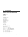
2.3.1
Selecting the Display Device
The SRM console environment variable determines to which display
device (VT-type terminal or VGA monitor) the console display is sent.
The console terminal that displays the SRM user interface can be either a serial
terminal (VT320 or higher, or equivalent) or a VGA monitor.
The SRM console environment variable determines the display device.
•
If you use a VT-type device as the console terminal, set the console environment variable to serial. The VT device can be connected to the MMJ
port or to the dedicated modem port.
•
If you use a VGA monitor as the console terminal, set the console environment variable to graphics.
You can verify the display device with the SRM show console command and
change the display device with the SRM set console command. If you change
the display device setting, you must reset the system (with the Reset button or
the init command) to put the new setting into effect.
In the following example, the operator displays the current console device (a
graphics device) and then resets it to a serial device. After the system initializes, output will be displayed on the serial terminal.
P00>>> show console
console
graphics
P00>>> set console serial
P00>>> init
.
.
.
Operation
2-11
2.3.2
Setting a Control Panel Message
You can create a customized message to be displayed on the operator
control panel after startup self-tests and diagnostics have been completed.
When the operating system is running, the control panel displays the console
revision. It is useful to create a customized message if you have a number of
systems and you want to identify each system by a node name.
You can use the SRM set ocp_text command to change this message. The
message can be up to 16 characters and must be entered in quotation marks, as
shown in Example 2–4.
Example 2–4 Set Ocp_Text Command
P00>>> set ocp_text “Node Alpha1”
2-12
ES45 Owner's Guide
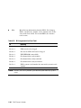
2.4
Displaying the Hardware Configuration
View the system hardware configuration from the SRM console. It is
useful to view the hardware configuration to ensure that the system
recognizes all devices, memory configuration, and network connections.
Use the following SRM console commands to view the system configuration.
show boot*
Displays the boot environment variables.
show config
Displays the logical configuration of interconnects and buses
on the system and the devices found on them.
show device
Displays the bootable devices and controllers in the system.
show fru
Displays the physical configuration of FRUs (field-replaceable
units). See Chapter 7 for information on this command.
show memory
Displays configuration of main memory.
Operation
2-13
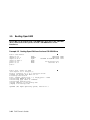
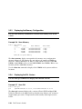
2.4.1
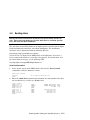
Displaying Boot Environment Variables
Use the show boot* command to list the boot environment variables.
Use the set command with a variable to set up the boot environment.
See Chapter 3 for more information on setting boot environment variables.
Example 2–5 Show Boot*
P00>>> show boot*
boot_dev
boot_file
boot_osflags
boot_reset
bootdef_dev
booted_dev
booted_file
booted_osflags
2-14
ES45 Owner's Guide
dka0.0.0.1.1
a
OFF
dka0.0.0.1.1
boot_dev
Device or device list from which booting is to be attempted, here SCSI device dka0.
boot_file
The default file name used for the primary bootstrap
when no file name is specified by the boot command.
boot_osflags
Boot flags, here the Tru64 UNIX “a” (autoboot) flag.
boot_reset
Action taken in response to an error halt or boot command. OFF, the default, indicates a warm boot (no full
reset is performed).
bootdef_dev
Device or device list from which booting is to be attempted
when no path is specified on the command line. Here,
SCSI device dka0.
booted_dev
The device from which booting occurred.
booted_file
The file name used for the primary bootstrap during the
last boot.
booted_osflags
Additional parameters, if any, specified by the last boot
command that are to be interpreted by system software.
Operation
2-15
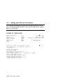
2.4.2
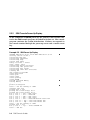
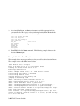
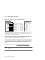
Displaying the Logical Hardware Configuration
Use the show config command to display the logical configuration. To
display the physical configuration, issue the show fru command.
Example 2–6 Show Config
P00>>> show config
Compaq Computer Corporation
Compaq AlphaServer ES45 Model 2B
Firmware
SRM Console:
PALcode:
Serial ROM:
RMC ROM:
RMC Flash ROM:
V5.9-9
OpenVMS PALcode V1.91-33, Tru64 UNIX PALcode V1.87-27
V2.18-F
V1.8
V1.7
Processors
CPU 0
CPU 1
CPU 2
CPU 3
Alpha
Alpha
Alpha
Alpha
Core Logic
Cchip
Dchip
PPchip 0
PPchip 1
TIG
Rev
Rev
Rev
Rev
Rev
Memory
Array
--------0
1
2
3
EV68CB
EV68CB
EV68CB
EV68CB
pass
pass
pass
pass
1000
1000
1000
1000
MHz
MHz
MHz
MHz
8MB
8MB
8MB
8MB
17
17
17
17
2.6
Size
---------4096Mb
1024Mb
4096Mb
1024Mb
Base Address
Intlv Mode
---------------- ---------0000000000000000
2-Way
0000000200000000
2-Way
0000000100000000
2-Way
0000000240000000
2-Way
Total Good Memory = 10240 MBytes
2-16
2.4
2.4
2.4
2.4
ES45 Owner's Guide
Bcache
Bcache
Bcache
Bcache
Firmware. Version numbers of the SRM console, PALcode, serial ROM,
RMC ROM, and RMC flash ROM
Processors. Processors present, processor version and clock speed, and
amount of backup cache
Core logic. Version numbers of the chips that form the interconnect on
the system board
Memory. Memory arrays and memory size
Continued on next page
Operation
2-17
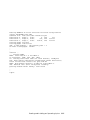
Example 2–6 Show Config (Continued)
Slot
7
8
9
10
11
12
16
Option
Acer Labs M1543C
ELSA GLoria Synergy
DECchip 21152-AA
DECchip 21041-AA
DE500-AA Network Con
Yukon PCI Hot-Plug C
Acer Labs M1543C IDE
Hose 0, Bus 0, PCI − 33 MHz
Bridge to Bus 1, ISA
vga0.0.0.8.0
Bridge to Bus 2, PCI
ewe0.0.0.10.0
00-00-F8-1F-AE-0A
ewf0.0.0.11.0
00-00-F8-1B-0B-24
dqa.0.0.16.0
dqb.0.1.16.0
dqa0.0.0.16.0
TOSHIBA CD-ROM XM-
6302B
Option
Floppy
Hose 0, Bus 1, ISA
dva0.0.0.1000.0
Slot
0
1
2
3
Option
DE500-BA
DE500-BA
DE500-BA
DE500-BA
Slot
1/0
Option
Adaptec AIC-7899
1/1
6
Slot
1
2
Slot
1/0
1/1
6
P00>>
Network
Network
Network
Network
Con
Con
Con
Con
Adaptec AIC-7899
Yukon PCI Hot-Plug C
Hose 0, Bus 2, PCI − 33 MHz
ewa0.0.0.2000.0
00-06-2B-00-E7-82
ewb0.0.0.2001.0
00-06-2B-00-E7-83
ewc0.0.0.2002.0
00-06-2B-00-E7-84
ewd0.0.0.2003.0
00-06-2B-00-E7-85
Hose 1, Bus 0, PCI − 66 MHz
pka0.7.0.1.1
SCSI Bus ID 7
dka0.0.0.1.1
COMPAQ BD018122C9
pkb0.7.0.101.1
SCSI Bus ID 7
Option
DEGPA-SA
DEGPA-SA
Hose 2, Bus 0, PCI − 66 MHz
Option
Adaptec AIC-7899
Adaptec AIC-7899
Yukon PCI Hot-Plug C
Hose 3, Bus 0, PCI − 66 MHz
pkc0.7.0.1.3
SCSI Bus ID 7
pkd0.7.0.101.3
SCSI Bus ID 7
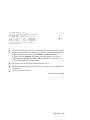
This part of the command output shows the PCI cards on a system that has
a 10-slot I/O backplane.
The “Slot” column lists the slots (logical IDs) seen by the system. Logical
IDs identify both installed PCI cards and onboard chips. In this example,
the onboard chips include the Yukon PCI hot-plug controller and the Acer
Labs M1543C IDE.
The logical IDs do not correspond directly to the physical slots into which
the devices are installed. See Table 2–2 for the correspondence between
logical IDs and physical slots.
2-18
ES45 Owner's Guide
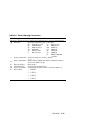
NOTE: The naming of devices (for example,dqa.0.0.15.0) follows the conventions given in Table 2–4.
The slots in Example 2–6 are from the Model 2B ten-slot backplane and
are explained below. An asterisk (*) indicates slots that contain a PCI
card.
Hose 0, Bus 0, PCI
Slot 7
Onboard Acer chip. Provides bridge to Bus 1, ISA
Slot 8*
VGA card
Slot 9*
Bridge chip to Bus 2, PCI
Slot 10*
Ethernet card
Slot 11*
Ethernet card
Slot 12
Onboard PCI hot-plug controller
Hose 0, Bus 1, ISA
The floppy drive. It is the only device that comes from the bridge.
Hose 0, Bus 2, PCI
Slots 0–3
Onboard controllers.
Hose 1, Bus 0, PCI
Slot 1/0, 1/1* Two-channel SCSI card
(Slot 2)
Not shown because no card installed.
Slot 6
Onboard PCI hot-plug controller
Hose 2, Bus 0, PCI
Slot 1*
Gigabit Ethernet card
Slot 2*
Gigabit Ethernet card
Hose 3, Bus 0, PCI
Slot 1/0, 1/1* Two-channel SCSI card
(Slot 2)
Not shown because no card installed.
Operation
2-19
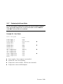
Table 2–1 Physical I/O Slots Map to Logical Slots: Model 1B
Physical Slot
SRM Logical ID (7-Slot)
1
Hose 0 Slot ID 11
2
Hose 0 Slot ID 10
3
Hose 2 Slot ID 5
4
Hose 3 Slot ID 2
5
Hose 3 Slot ID 1
7
Hose 1 Slot ID 2
8
Hose 1 Slot ID 1
Table 2–2 Physical I/O Slots Map to Logical Slots: Model 2B
Physical Slot
2-20
SRM Logical ID
1
Hose 2 Slot ID 1
2
Hose 2 Slot ID 2
3
Hose 0 Slot ID 11
4
Hose 3 Slot ID 2
5
Hose 3 Slot ID 1
6
Hose 0 Slot ID 10
7
Hose 1 Slot ID 2
8
Hose 1 Slot ID 1
9
Hose 0 Slot ID 9
10
Hose 0 Slot ID 8
ES45 Owner's Guide
Table 2–3 Physical I/O Slots Map to Logical Slots: Model 3B
Physical Slot
SRM Logical ID (10-Slot Legacy PCI)
1
Hose 2 Slot ID 1
2
Hose 2 Slot ID 2
3
Hose 0 Slot ID 11
4
Hose 3 Slot ID 2
5
Hose 3 Slot ID 1
6
Hose 0 Slot ID 10
7
Hose 1 Slot ID 2
8
Hose 1 Slot ID 1
9
Hose 0 Slot ID 9
10
Hose 0 Slot ID 8
Operation
2-21
2.4.3
Displaying the Bootable Devices
Use the show device command to display the devices from which the
operating system can be booted.
Example 2–7 Show Device
P00>>> show device
dka0.0.0.1.1
dka100.1.0.1.1
dka200.2.0.1.1
dkb0.0.0.3.1
dqa0.0.0.15.0
dva0.0.0.1000.0
ewa0.0.0.4.1
ewb0.0.0.2002.1
pka0.7.0.1.1
pkb0.7.0.3.1
pkc0.7.0.2000.1
pkd0.7.0.2001.1
2-22
ES45 Owner's Guide
DKA0
DKA100
DKA200
DKB0
DQA0
DVA0
EWA0
EWB0
PKA0
PKB0
PKC0
PKD0
RZ2DD-LS
RZ2DD-LS
RZ1CB-CS
RZ25
TOSHIBA CD-ROM XM-6302B
00-00-F8-09-90-FF
00-06-2B-00-25-5B
SCSI Bus ID 7
SCSI Bus ID 7
SCSI Bus ID 7
SCSI Bus ID 7
0306
0306
0844
0900
1012
Table 2–4 Device Naming Conventions
Category
Description
The device, dqa0 is used as an example in the following device category and description.
Two-letter designator of port or class driver
dq Driver ID
dk
SCSI drive or CD
ew
Ethernet port
dq
IDE CD-ROM
fw
FDDI device
dr
RAID set device
mk
SCSI tape
du
DSSI disk
mu
DSSI tape
dv
Diskette drive
pk
SCSI port
ei
Ethernet port
pu
DSSI port
pz
KZPCC-CE RAID
controller
Storage adapter ID
One-letter designator of storage adapter
a
(a, b, c…).
Device unit number Unique number (MSCP unit number). SCSI unit numbers
0
are forced to 100 X node ID.
Bus node number
Bus node ID.
0
Channel number
Used for multi-channel devices.
0
15 Logical slot number Corresponds to PCI slot number, as shown in Table 2–2.
Hose number
0
• 0 PCI 0
•
1 PCI 1
•
2 PCI 2
•
3 PCI 3
Operation
2-23
2.4.4
Viewing the Memory Configuration
Use the show memory command to view the configuration of main
memory.
Example 2–8 Show Memory
P00>>> show memory
Array
Size
--------- ---------0
4096Mb
1
1024Mb
2
4096Mb
3
1024Mb
Base Address
Intlv Mode
---------------- ---------0000000000000000
2-Way
0000000200000000
2-Way
0000000100000000
2-Way
0000000240000000
2-Way
10240 MB of System Memory
The show memory display corresponds to the memory array configuration described in Chapter 4. The display does not indicate the number of DIMMs or
the DIMM size. Thus, in Example 2–8, Array 3 could consist of two sets of 128
MB DIMMs (eight DIMMs) or one set of 256 MB DIMMs (four DIMMs). Either
combination provides 1024 MB of memory.
The output of the show memory command also provides the memory interleaving status of the system.
Use the show fru command to display the DIMMs in the system and their location. See Chapter 7.
2-24
ES45 Owner's Guide
2.5
Setting SRM Environment Variables
You may need to set several SRM console environment variables and
built-in utilities to configure the system.
Set environment variables at the P00>>> prompt.
•
To check the setting for a specific environment variable, enter the show
envar command, where the name of the environment variable is substituted for envar. To see a list of the environment variables, enter the
show* command.
•
To reset an environment variable, use the set envar command, where the
name of the environment variable is substituted for envar.
The environment variables used to set up the boot environment are described in
Chapter 3. Chapter 5 covers other environment variables you are likely to use.
Operation
2-25
2.6
Setting Console Security
You can set the SRM console to secure mode to prevent unauthorized
persons from modifying the system parameters or otherwise tampering
with the system from the console.
When the SRM is set to secure mode, you can use only two console commands:
•
The boot command, to boot the operating system.
•
The continue command, to resume running the operating system if you
have inadvertently halted the system.
The boot command cannot take command-line parameters when the console is
in secure mode. The console boots the operating system using the environment
variables stored in NVRAM (boot_file, bootdef_dev, boot_flags).
The console security commands are as follows:
set password
set secure
These commands put the console into secure mode.
clear password
Exits secure mode.
login
Turns off console security for the current session. Once you
enter the login command in secure mode, you can enter any
SRM command as usual. However, the system automatically returns to secure mode when you enter the boot or
continue command or when you reset the system.
NOTE: The security features work only if access to the system hardware is denied to unauthorized persons. Be sure the system is available only to
authorized persons.
2-26
ES45 Owner's Guide
2.6.1
Setting the Console Password
Set the console password with the set password command. A password
is required for operating the system in secure mode.
Example 2–9 Set Password
P00>>> set password
Please enter the password:
Please enter the password again:
P00>>>
P00>>> set password
Please enter the password:
Please enter the password again:
Now enter the old password:
P00>>>
P00>>> set password
Please enter the password:
Password length must be between 15 and 30 characters
P00>>>
Operation
2-27
The set password command sets the console password for the first time or
changes an existing password. It is necessary to set the password only if the
system is going to operate in secure mode.
The syntax is:
set password
Setting a password. If a password has not been set and the set password
command is issued, the console prompts for a password and verification.
The password and verification are not echoed.
Changing a password. If a password has been set and the set password
command is issued, the console prompts for the new password and verification, then prompts for the old password. The password is not changed if the
validation password entered does not match the existing password stored in
NVRAM.
The password length must be between 15 and 30 alphanumeric characters.
Any characters entered after the 30th character are not stored.
2-28
ES45 Owner's Guide
2.6.2
Setting the Console to Secure Mode
To set the console to secure mode, first set the password. Then enter
the set secure command. The system immediately enters secure mode.
Example 2–10 Set Secure
P00>>> set secure
Console is secure. Please login.
P00>>> b dkb0
Console is secure - parameters are not allowed.
P00>>> login
Please enter the password:
P00>>> b dkb0
(boot dkb0.0.0.3.1)
.
.
.
The set secure command enables secure mode. If no password has been set,
you are prompted to set the password. Once you set a password and enter the
set secure command, secure mode is in effect immediately and only the continue, boot (using the stored parameters), and login commands can be performed.
The syntax is:
set secure
The console is put into secure mode, and then the operator attempts to boot
the operating system with command-line parameters. A message is displayed indicating that boot parameters are not allowed when the system is
in secure mode.
The login command is entered to turn off security features for the current
console session. After successfully logging in, the operator enters a boot
command with command-line parameters.
Operation
2-29
2.6.3
Turning Off Security During a Console Session
The login command turns off the security features, enabling access to
all SRM console commands during the current console session. The
system automatically returns to secure mode as soon as the boot or
continue command is entered or when the system is reset.
Example 2–11 Login
P00>>>
Secure
P00>>>
Please
Please
P00>>>
Please
P00>>>
login
not set. Please set the password.
set password
enter the password:
enter the password again:
login
enter the password.
show boot*
The login command is entered, but the system is not in secure mode. A
password must be set.
A password is set.
The login command is entered. After the password is entered, console security is turned off for the current session and the operator can enter commands.
2-30
ES45 Owner's Guide
When you enter the login command, you are prompted for the current system
password. If a password has not been set, a message is displayed indicating that
there is no password in NVRAM. If a password has been set, this prompt is displayed:
Please enter the password:
If the password entered matches the password in NVRAM, when the prompt is
redisplayed the console is no longer in secure mode and all console commands
can be performed during the current console session.
If You Forget the Password
If you forget the current password, use the login command in conjunction with
the control panel Halt button to clear the password, as follows:
1. Enter the login command:
P00>>> login
2. When prompted for the password, press the Halt button to the latched position and then press the Return (or Enter) key.
3. Press the Halt button to release the halt. The password is now cleared and
the console cannot be put into secure mode unless you set a new password.
Operation
2-31
2.6.4
Returning to User Mode
The clear password command clears the password environment variable, setting it to zero. Once the password is cleared, you are returned
to user mode.
Example 2–12 Clear Password
P00>>> clear password
Please enter the password:
Console is secure
P00>>> clear password
Please enter the password:
Password successfully cleared.
P00>>>
The wrong password is entered. The system remains in secure mode.
The password is successfully cleared.
The clear password command is used to exit secure mode and return to user
mode. To use clear password, you must know the current password. Once
you clear the password, the console is no longer secure.
To clear the password without knowing the current password, you must use the
login command in conjunction with the Halt button, as described in Section
2.6.3.
2-32
ES45 Owner's Guide
2.7
Updating Firmware
Typically, you update system firmware whenever the operating system
is updated. You might also need to update firmware if you add I/O device controllers and adapters, if enhancements are made to the firmware, or if the serial ROM or RMC firmware become corrupted.
Sources of Firmware Updates
The system firmware resides in the flash ROM located on the system board.
The Alpha Systems Firmware Update Kit comes on a CD-ROM, which is updated quarterly. You can also obtain Alpha firmware updates from the Internet.
Quarterly Update Service
The Alpha Systems Firmware Update Kit CD-ROM is available by subscription
from Compaq.
Alpha Firmware Internet Access
You can also obtain Alpha firmware update files from the Internet:
http://ftp.digital.com/pub/DEC/Alpha/firmware/
If you do not have a Web browser, you can access files using anonymous ftp:
$ ftp ftp.digital.com
Name (ftp.digital.com:mcdowell): anonymous
331 Guest login ok, send ident as password.
Password:
230 Guest login ok, access restrictions apply.
Remote system type is UNIX.
Using binary mode to transfer files.
ftp> cd /pub/DEC/Alpha/firmware
ftp> ls
...
ftp> cd v5.0
ftp> ls
...
ftp> cd es45 (if that's what the directory will be called)
ftp> get README
The README file explains how to download firmware updates.
Operation
2-33
2.7.1
Firmware Update Utility
The system firmware is updated from a Loadable Firmware Update
Utility (LFU). When you boot the medium containing the update image, the LFU banner and command descriptions are displayed. Enter
commands at the UPD> prompt.
Before updating the firmware, enter the list command to list the current revision of the firmware. Enter the update command to update the firmware
automatically.
Example 2–13 Update Utility Display
Checking dqa0.0.0.16.0 for the option firmware files. . .
Checking dva0.0.0.1000.0 for the option firmware files. . .
Option firmware files were not found on CD or floppy.
If you want to load the options firmware,
please enter the device on which the files are located(ewa0),
or just hit <return> to proceed with a standard console update:
***** Loadable Firmware Update Utility *****
-------------------------------------------------------------Function
Description
-------------------------------------------------------------Display
Displays the system's configuration table.
Exit
Done exit LFU (reset).
List
Lists the device, revision, firmware name, and
update revision.
Update
Replaces current firmware with loadable data image.
Verify
Compares loadable and hardware images.
? or Help Scrolls this function table.
-------------------------------------------------------------UPD> list
2-34
ES45 Owner's Guide
Device
Current Revision
Filename
Update Revision
SRM
V5.9-8
srm_fw
V5.9-9
srom
V2.17-F
srom_fw
V2.18-F
UPD> u
Confirm update on:
SRM
srom
[Y/(N)]y
WARNING: updates may take several minutes to complete for each device.
DO NOT ABORT!
SRM
Updating to V5.9-9...
Verifying V5.9-9... PASSED.
srom
Updating to V2.18-F... Verifying V2.18-F...PASSED.
UPD>
Operation
2-35
2.7.2
Manual Updates
If RMC firmware or serial ROM (SROM) become corrupted, you can
perform a manual update.
1. Boot the update medium.
2. At the UPD> prompt, enter the exit command and answer y at the prompt:
UPD> exit
Do you want to do a manual update [y/(n)] y
AlphaServer ES45 Console V5.9-9, built on Jan 9,2001 at
05:02:30
3. To update RMC firmware, enter update rmc. To update the serial ROM
(SROM), enter update srom. For example:
UPD> update srom
The remainder of the display is similar to that shown in Example 2–13.
2-36
ES45 Owner's Guide
2.7.3
Updating from the CD-ROM
You can update the system firmware from CD-ROM.
1. At the SRM console prompt, enter the show device command to determine
the drive name of the CD-ROM drive.
2. Load the Alpha Systems Firmware Update CD into the drive.
3. Boot the system from the CD, using the drive name determined in step 1
(for example, dqa0).
P00>>> boot dqa0
4. Enter the update command at the UPD> prompt.
5. When the update is complete, exit from the Firmware Update Utility.
UPD> exit
Operation
2-37
2.7.4
Updating from an OpenVMS System Disk
You can update the firmware from an OpenVMS system disk.
1. Download the firmware update image from the Firmware Updates Web site.
2. Rename the downloaded file to fwupdate.exe.
3. Enter the following commands on the OpenVMS Alpha system:
$ set file/attr=(rfm:fix,lrl:512,mrs:512,rat:none) fwupdate.exe
$ copy/contiguous fwupdate.exe "system_disk":[sys0.sysexe]
NOTE: Insert the name of your system disk in place of "system_disk,” for
example, dka100:.
4. Shut down the operating system to get to the SRM console prompt.
5. Boot the update utility from the SRM console as follows:
P00>>> boot dka100 -flags 0,a0
NOTE: Replace dka100 with the name of the system disk, if different.
6. After some messages are displayed, you will be prompted for the bootfile.
Enter the directory and file name as follows :
Bootfile: [sys0.sysexe]fwupdate.exe
7. Enter the update command at the UPD> prompt.
2-38
ES45 Owner's Guide
2.7.5
Updating from the Network
You can update firmware from the network using the MOP protocol for
OpenVMS or the BOOTP protocol for Tru64 UNIX.
Updating Firmware Using BOOTP
1. Download the firmware update image from the Firmware Updates Web site.
2. Copy the downloaded file to a UNIX based network server for BOOTP booting on the system. For details on configuring the BOOTP server, refer to
Tru64 UNIX documentation or the system's Firmware Release Notes document.
3. Enter the update command at the UPD> prompt.
Updating Firmware Using MOP
1. Download the firmware update image from the Firmware Updates Web site.
2. Copy the downloaded file to an OpenVMS based network server for MOP
booting on the system. For details on configuring the MOP server, refer to
OpenVMS documentation or the system's Firmware Release Notes document.
3. To ensure that the downloaded file is in a proper VMS fixed record format,
enter the following command before using the file for MOP booting:
$ set file/attr=(rfm:fix,lrl:512,mrs:512,rat:none) “fwupdate.sys”
NOTE: Replace “fwupdate.sys” with the name of the firmware image you
downloaded.
4. Boot the update file. For example:
P00>>> boot -file fwupdate eia0
5. Enter the update command at the UPD> prompt.
Operation
2-39
Chapter 3
Booting and Installing
an Operating System
This chapter gives instructions for booting the Tru64 UNIX, OpenVMS, or
Linux operating systems and for starting an operating system installation. Refer to your operating system documentation for complete instructions on booting
or starting an installation.
The following topics are covered:
•
Setting Boot Options
•
Booting Tru64 UNIX
•
Starting a Tru64 UNIX Installation
•
Booting Linux
•
Booting OpenVMS
•
Starting an OpenVMS Installation
NOTE: Your system may have been delivered to you with factory-installed software (FIS); that is, with a version of the operating system already installed. If so, refer to the FIS documentation included with your system
to boot your operating system for the first time. Linux-ready systems do
not come with factory-installed software.
Booting and Installing an Operating System 3-1
3.1
Setting Boot Options
You can set a default boot device, boot flags, and network boot protocols by using the SRM set command with environment variables. Once
these environment variables are set, the boot command defaults to the
stored values. You can override the stored values for the current boot
session by entering parameters on the boot command line. For more
information on setting boot options, see Chapter 5.
The SRM boot-related environment variables are listed below and described in
the following sections:
auto_action
Determines the default action the system takes when the
system is power cycled, reset, or experiences a failure.
bootdef_dev
Device or device list from which booting is to be attempted
when no path is specified on the command line.
boot_file
Specifies a default file name to be used for booting when
no file name is specified by the boot command.
boot_osflags
Defines parameters (boot flags) used by the operating system to determine some aspects of a system bootstrap.
ei*0_inet_init or
ew*0_inet_init
Determines whether the interface's internal Internet database is initialized from nvram or from a network server
(through the bootp protocol). Set this environment variable if you are booting Tru64 UNIX from a RIS server.
ei*0_protocols or
ew*0_protocols
Defines a default network boot protocol (bootp or mop).
3-2
ES45 Owner's Guide
3.1.1
auto_action
The SRM auto_action environment variable determines the default action the system takes when the system is power cycled, reset, or experiences a failure.
Systems can boot automatically (if set to autoboot) from the default boot device
under the following conditions:
•
When you first turn on system power
•
When you power cycle or reset the system
•
When system power comes on after a power failure
•
After a bugcheck (OpenVMS) or panic (Tru64 UNIX or Linux)
The factory setting for auto_action is halt. The halt setting causes the system
to stop in the SRM console. You must then boot the operating system manually.
For maximum system availability, auto_action can be set to boot or restart.
•
With the boot setting, the operating system boots automatically after the
SRM init command is issued or the Reset button is pressed.
•
With the restart setting, the operating system boots automatically after the
SRM init command is issued or the Reset button is pressed, and it also reboots after an operating system crash.
Example
To set the default action to boot, enter the following SRM commands:
P00>>> set auto_action boot
P00>>> init
Booting and Installing an Operating System 3-3
3.1.2
bootdef_dev
The bootdef_dev environment variable specifies one or more devices
from which to boot the operating system. When more than one device is
specified, the system searches in the order listed and boots from the
first device.
Enter the show bootdef_dev command to display the current default boot device. Enter the show device command for a list of all devices in the system.
The syntax is:
set bootdef_dev boot_device
boot_device
The name of the device on which the system software has been
loaded. To specify more than one device, separate the names with
commas.
Example
In this example, two boot devices are specified. The system will try booting
from dkb0 and, if unsuccessful, will boot from dka0.
P00>>> set bootdef_dev dkb0, dka0
NOTE: When you set the bootdef_dev environment variable, it is recommended that you set the operating system boot parameters as well, using the set boot_osflags command.
3-4
ES45 Owner's Guide
3.1.3
boot_file
The boot_file environment variable specifies the default file name to be
used for booting when no file name is specified by the boot command.
The syntax is:
set boot_file filename
Example
P00>>> set boot_file “”
NOTE: This command clears the boot file setting and sets the string to empty.
Booting and Installing an Operating System 3-5
3.1.4
boot_osflags
The boot_osflags environment variable sets the default boot flags and,
for OpenVMS, a root number.
Boot flags contain information used by the operating system to determine some
aspects of a system bootstrap. Under normal circumstances, you can use the
default boot flag settings.
To change the boot flags for the current boot only, use the flags_value argument
with the boot command.
The syntax is:
set boot_osflags flags_value
The flags_value argument is specific to the operating system.
Tru64 UNIX Systems
Tru64 UNIX systems take a single ASCII character as the flags_value argument.
a
Load operating system software from the specified boot device (autoboot). Boot to multiuser mode.
i
Prompt for the name of a file to load and other options (boot interactively). Boot to single-user mode.
s
Stop in single-user mode. Boots /vmunix to single-user mode and stops
at the # (root) prompt.
D Full dump; implies “s” as well. By default, if UNIX crashes, it completes a partial memory dump. Specifying “D” forces a full dump at
system crash.
Example
The following setting will autoboot Tru64 UNIX to multiuser mode when you
enter the boot command.
P00>>> set boot_osflags a
3-6
ES45 Owner's Guide
Linux Systems
If aboot.conf contains (0: 1/vmlinux.gz ro root=/dev/sda2), the system can be
booted by one of the following methods:
1.
set boot_file
set boot_osflags 0
boot dka0
---or--2.
boot dka0 -file "" -flags 0
---or--3.
set boot_file 1/vmlinuz.gz
set boot_osflags "ro root=/dev/sda2"
boot dka0
Example
Single-user mode is typically used for troubleshooting. To make system changes
at this run level, you must have read/write privileges. The command to boot
Linux into single-user mode is similar to the following example, where “/” root is
in partition 2 of dka0, and the kernel is in /boot/compaq.gz.
P00>>> boot –file “1/vmlinux.gz” –flags “root=/dev/sda2 rw single”
Example
This following command sets the boot_osflags environment variable for Linux:
P00>>> set boot_osflags 0
Booting and Installing an Operating System 3-7
OpenVMS Systems
OpenVMS systems require an ordered pair as the flags_value argument:
root_number and boot_flags.
root_number
boot_flags
3-8
Directory number of the system disk on which OpenVMS files
are located. For example:
root_number
Root Directory
0 (default)
[SYS0.SYSEXE]
1
[SYS1.SYSEXE]
2
[SYS2.SYSEXE]
3
[SYS3.SYSEXE]
The hexadecimal value of the bit number or numbers set. To
specify multiple boot flags, add the flag values (logical OR).
For example, the flag value 10080 executes both the 80 and
10000 flag settings. See Table 3–1.
ES45 Owner's Guide
Table 3–1 OpenVMS Boot Flag Settings
Flags_Value
Bit Number
Meaning
1
0
Bootstrap conversationally (enables you to modify SYSGEN parameters in SYSBOOT).
2
1
Map XDELTA to a running system.
4
2
Stop at initial system breakpoint.
8
3
Perform diagnostic bootstrap.
10
4
Stop at the bootstrap breakpoints.
20
5
Omit header from secondary bootstrap image.
80
7
Prompt for the name of the secondary bootstrap
file.
100
8
Halt before secondary bootstrap.
10000
16
Display debug messages during booting.
20000
17
Display user messages during booting.
Examples
In the following OpenVMS example, root_number is set to 2 and boot_flags is set
to 1. With this setting, the system will boot from root directory SYS2.SYSEXE
to the SYSBOOT prompt when you enter the boot command.
P00>>> set boot_osflags 2,1
In the following OpenVMS example, root_number is set to 0 and boot_flags is set
to 80. With this setting, you are prompted for the name of the secondary bootstrap file when you enter the boot command.
P00>>> set boot_osflags 0,80
3.1.5
ei*0_inet_init or ew*0_inet_init
The ei*0_inet_init or ew*0_inet_init environment variable determines
whether the interface's internal Internet database is initialized from
nvram or from a network server (through the bootp protocol).
Booting and Installing an Operating System 3-9
Legal values are nvram and bootp. The default value is bootp. Set this environment variable if you are booting Tru64 UNIX from a RIS server.
To list the network devices on your system, enter the show device command.
The Ethernet controllers start with the letters “ei” or “ew,” for example, ewa0.
The third letter is the adapter ID for the specific Ethernet controller. Replace
the asterisk (*) with the adapter ID letter when entering the command.
The syntax is:
set ei*0_inet_init value or
set ei*0_inet_init value
Example
P00>>> set ewa0_inet_init bootp
3-10
ES45 Owner's Guide
3.1.6
ei*0_protocols or ew*0_protocols
The ei*0_protocols or ew*0_protocols environment variable sets network protocols for booting and other functions.
To list the network devices on your system, enter the show device command.
The Ethernet controllers start with the letters “ei” or “ew,” for example, ewa0.
The third letter is the adapter ID for the specific Ethernet controller. Replace
the asterisk (*) with the adapter ID letter when entering the command.
The syntax is:
set ei*0_protocols protocol_value or
set ei*0_protocols protocol_value
The options for protocol_value are:
mop (default)
Sets the network protocol to mop (Maintenance Operations
Protocol), the setting typically used with the OpenVMS operating system.
bootp
Sets the network protocol to bootp, the setting typically used
with the Tru64 UNIX operating system.
bootp,mop
When both are listed, the system attempts to use the mop
protocol first, regardless of which is listed first. If not successful, it then attempts the bootp protocol.
Booting and Installing an Operating System 3-11
Example
P00>>> show device
.
.
.
ewa0.0.0.1001.0
EWA0
ewb0.0.0.12.0
EWB0
ewc0.0.0.13.0
EWC0
.
.
.
P00>>> set ewa0_protocols bootp
P00>>> show ewa0_protocols
ewa0_protocols
bootp
3-12
ES45 Owner's Guide
08-00-2B-3E-BC-B5
00-00-C0-33-E0-0D
08-00-2B-E6-4B-F3
3.2
Booting Tru64 UNIX
Tru64 UNIX can be booted from a CD-ROM on a local drive (a CD-ROM
drive connected to the system), from a local SCSI disk, or from a UNIX
RIS server.
Example 3–1 Booting Tru64 UNIX from a Local SCSI Disk
P00>>> sho dev
dka0.0.0.1.1
dka100.1.0.1.1
dka200.2.0.1.1
dka300.3.0.1.1
dkc0.0.0.1.0
dkc100.1.0.1.0
dkc200.2.0.1.0
dkc300.3.0.1.0
dqa0.0.0.15.0
dva0.0.0.1000.0
ewa0.0.0.4.1
pka0.7.0.1.1
DKA0
DKA100
DKA200
DKA300
DKC0
DKC100
DKC200
DKC300
DQA0
DVA0
EWA0
PKA0
RZ2ED-LS
RZ2ED-LS
RZ2DD-LS
RZ2DD-LS
RZ2DD-LS
RZ2DD-LS
RZ2DD-LS
RZ2DD-LS
TOSHIBA CD-ROM XM-6202B
00-00-F8-10-67-97
SCSI Bus ID 7
P00>>> boot
(boot dka0.0.0.8.0 -flags A)
block 0 of dka0.0.0.8.0 is a valid boot block
reading 19 blocks from dka0.0.0.8.0
bootstrap code read in
base = 2da000, image_start = 0, image_bytes = 2600
initializing HWRPB at 2000
initializing page table at 27fff0000
initializing machine state
setting affinity to the primary CPU
jumping to bootstrap code
0306
0306
0306
0306
0306
0306
0306
0306
1110
UNIX boot - Tuesday May 22, 2001
Loading vmunix ...
Loading at 0xfffffc0000430000
Sizes:
text = 5454592
data =
885872
bss = 1616192
Starting at 0xfffffc00004403e0
Alpha boot: available memory from 0xc9d4000 to 0x27ffee000
Compaq Tru64 UNIX V5.1A-8 (Rev. 1764); Mon Jun 11 16:12:47 EDT 2001
physical memory = 10240.00 megabytes.
available memory = 10038.09 megabytes.
Booting and Installing an Operating System 3-13
using 39275 buffers containing 306.83 megabytes of memory
Master cpu at slot 0
Starting secondary cpu 1
Starting secondary cpu 2
Starting secondary cpu 3
Firmware revision: 5.9-9
PALcode: UNIX version 1.87-27
Compaq AlphaServer ES45 Model 2
.
.
.
.
The system is ready.
Compaq Tru64 UNIX V5.1A-8 (Rev. 1764) console
login:
Example 3–1 shows a boot from a local SCSI drive. The example is abbreviated.
For complete instructions on booting UNIX, see the Tru64 UNIX Installation
Guide.
Perform the following tasks to boot a UNIX system:
1. Power up the system. The system stops at the SRM console prompt,
P00>>>.
2. Set boot environment variables, if desired. See Section 3.1.
3. Install the boot medium. For a network boot, see Section 3.2.1.
4. Enter the show device command
drive for your device.
5. Enter the boot command
3-14
ES45 Owner's Guide
to determine the unit number of the
and command-line parameters.
3.2.1
Booting Tru64 UNIX over the Network
To boot your Tru64 UNIX system over the network, make sure the system is registered on a Remote Installation Services (RIS) server. See
the Tru64 UNIX document entitled Sharing Software on a Local Area
Network for registration information.
Example 3–2 RIS Boot
P00>>> show device
dka0.0.0.1.1
DKA0
dka100.1.0.1.1
DKA100
dka200.2.0.1.1
DKA200
dkb0.0.0.3.1
DKB0
dqa0.0.0.15.0
DQA0
dva0.0.0.1000.0
DVA0
ewa0.0.0.4.1
EWA0
ewb0.0.0.2002.1
EWB0
pka0.7.0.1.1
PKA0
pkb0.7.0.3.1
PKB0
P00>>> set ewa0_protocols bootp
P00>>> set ewa0_inet_init bootp
P00>>> boot ewa0 Da
.
RZ2DD-LS
RZ2DD-LS
RZ1CB-CS
RZ25
TOSHIBA CD-ROM XM-6302B
0306
0306
0844
0900
1012
00-00-F8-09-90-FF
00-06-2B-00-25-5B
SCSI Bus ID 7
SCSI Bus ID 7
.
.
Booting and Installing an Operating System 3-15
Systems running Tru64 UNIX support network adapters, designated ew*0 or
ei*0. The asterisk stands for the adapter ID (a, b, c, and so on).
1.
Power up the system. The system stops at the SRM console prompt,
P00>>>.
2.
Set boot environment variables, if desired. See Section 3.1.
3.
Enter the show device command
drive for your device.
4.
Enter the following commands. Example 3–2 assumes you are booting from
ewa0. If you are booting from another drive, enter that device name instead.
to determine the unit number of the
P00>>> set ewa0_protocols bootp
P00>>> set ewa0_inet_init bootp
enables the bootp network protocol for booting over
The first command
the Ethernet controller. The second command
sets the internal Internet
database to initialize from the network server through the bootp protocol.
5.
and command-line parameters (if you have not
Enter the boot command
set the associated environment variables). In Example 3–2 the boot command sets the system to boot automatically from ewa0 and specifies a full
memory dump (Da) in case of a system shutdown.
For complete instructions on booting Tru64 UNIX over the network, see the
Tru64 UNIX Installation Guide.
3-16
ES45 Owner's Guide
3.3
Starting a Tru64 UNIX Installation
Tru64 UNIX is installed from the CD-ROM drive connected to the system. The display that you see after you boot the CD depends on
whether your system console is a VGA monitor or a serial terminal.
Example 3–3 Text-Based Installation Display
P00>>> b dqa0
(boot dqa0.0.0.15.0 -flags a
block 0 of dqa0.0.0.15.0 is a valid boot block
reading 16 blocks from dqa0.0.0.15.0
bootstrap code read in
base = 200000, image_start = 0, image_bytes = 2000
initializing HWRPB at 2000
initializing page table at 1fff0000
initializing machine state
setting affinity to the primary CPU
jumping to bootstrap code
Tru64 UNIX boot - Thu Dec 16 15:03:19 EST 1999
Loading vmunix ...
.
.
Initializing system for Tru64 UNIX installation.
wait...
Please
*** Performing CDROM Installation
Loading installation process and scanning system hardware.
Welcome to the UNIX Installation Procedure
This procedure installs UNIX onto your system. You will be
asked a series of system configuration questions. Until you
answer all questions, your system is not changed in any way.
During the question and answer session, you can go back to any
previous question and change your answer by entering: history
You can get more information about a question by entering:
help
Booting and Installing an Operating System 3-17
There are two types of installations:
o
The Default Installation installs a mandatory set of
software subsets on a predetermined file system layout.
o
The Custom Installation installs a mandatory set of
software subsets plus optional software subsets that you
select. You can customize the file system layout.
The UNIX Shell
with superuser
perienced UNIX
system or disk
option puts your system in single-user mode
privileges. This option is provided for exsystem administrators who want to perform file
maintenance tasks before the installation.
The Installation Guide contains more information about installing UNIX.
1) Default Installation
2) Custom Installation
3) UNIX Shell
Enter your choice:
1. Boot the operating system from the CD-ROM drive connected to the system.
2. Follow the UNIX installation procedure that is displayed after the installation process is loaded.
•
If your system console is a VGA monitor, the X Server is started and an Installation Setup window is displayed. Click on the fields in the Installation
Setup window to enter your responses to the installation procedure.
•
If your system console is a serial terminal, a text-based installation procedure is displayed, as shown in Example 3–3. Enter the choices appropriate
for your system.
See the Tru64 UNIX Installation Guide for complete installation instructions.
3-18
ES45 Owner's Guide
3.4
Booting Linux
Obtain the Linux installation document and install Linux on the system. Then verify the firmware version, boot device, and boot parameters, and issue the boot command.
The procedure for installing Linux on an Alpha system is described in the Alpha
Linux installation document for your Linux distribution. The installation
document can be downloaded from the following Web site:
http://www.compaq.com/alphaserver/linux
You need V5.6-3 or higher of the SRM console to install Linux. If you have a
lower version of the firmware, you will need to upgrade. For instructions and
the latest firmware images, see the following URL:
http://ftp.digital.com/pub/DEC/Alpha/firmware/
Linux Boot Procedure
1. Power up the system to the SRM console and enter the show version
command to verify the firmware version.
P00>> show version
version
P00>>
V5.6-3 Mar 12 2001 08:36:11
2. Enter the show device command to determine the unit number of the drive
for your boot device, in this case dka0.0.0.17.0.
P00>>> sh dev
dka0.0.0.17.0
dka200.2.0.7.1
dqa0.0.0.105.0
dva0.0.0.0.0
ewa0.0.0.9.0
pka0.7.0.7.1
pkb0.7.0.6.0
pkc0.7.0.106.0
P00>>>
DKA0
DKA200
DQA0
DVA0
EWA0
PKA0
PKB0
PKC0
COMPAQ BD018122C9
COMPAQ BD018122C9
CD-224E
B016
B016
9.5B
00-00-F8-1B-9C-47
SCSI Bus ID 7
SCSI Bus ID 7
SCSI Bus ID 7
Booting and Installing an Operating System 3-19
3. After installing Linux, set boot environment variables appropriately for
your installation. The typical values indicating booting from dka0 with the
first aboot.conf entry are shown in this example.
P00>>> set bootdef_dev dka0
P00>>> set boot_file
P00>>> set boot_osflags 0
P00>>> show boot*
boot_dev
dka0.0.0.17.0
boot_file
boot_osflags
0
boot_reset
OFF
bootdef_dev
booted_dev
booted_file
booted_osflags
4. From SRM enter the boot command. The following example shows an abbreviated boot output.
Example 3–4 Linux Boot Output
This example shows messages similar to what you will see when booting Linux.
The example is from a RedHat Linux 7.0 boot.
>>> boot
(boot dka0.0.0.8.0 -flags 0)
block 0 of dka0.0.0.8.0 is a valid boot block
reading 163 blocks from dka0.0.0.8.0
bootstrap code read in
base = 2d4000, image_start = 0, image_bytes = 14600
initializing HWRPB at 2000
initializing page table at 7fff0000
initializing machine state
setting affinity to the primary CPU
jumping to bootstrap code
aboot: Linux/Alpha SRM bootloader version 0.7
aboot: switching to OSF/1 PALcode version 1.87
aboot: booting from device 'SCSI 0 8 0 0 0 0 0'
aboot: valid disklabel found: 3 partitions.
aboot: loading uncompressed vmlinuz-2.4.3-7privateer2smp...
aboot: loading compressed vmlinuz-2.4.3-7privateer2smp...
aboot: zero-filling 369720 bytes at 0xfffffc0000ce9400
aboot: starting kernel vmlinuz-2.4.3-7privateer2smp with arguments root=/dev/sda2 console=ttyS0
Linux version 2.4.3-7privateer2smp (root@privateer) (gcc version 2.96 20000731 (Red Hat Linux 7.1 2.96-85)) #1 SMP Thu May
24 11:01:14 EDT 2001
3-20
ES45 Owner's Guide
Booting GENERIC on Titan variation Privateer using machine
vector PRIVATEER from SRM
Command line: root=/dev/sda2 console=ttyS0
memcluster 0, usage 1, start
0, end
362
memcluster 1, usage 0, start
362, end
262135
memcluster 2, usage 1, start
262135, end
262144
freeing pages 362:1024
freeing pages 1700:262135
SMP: 4 CPUs probed -- cpu_present_mask = f
On node 0 totalpages: 262144
.
.
.
autorun ...
... autorun DONE.
NET4: Linux TCP/IP 1.0 for NET4.0
IP Protocols: ICMP, UDP, TCP, IGMP
IP: routing cache hash table of 16384 buckets, 256Kbytes
TCP: Hash tables configured (established 524288 bind 65536)
Linux IP multicast router 0.06 plus PIM-SM
NET4: Unix domain sockets 1.0/SMP for Linux NET4.0.
VFS: Mounted root (ext2 filesystem) readonly.
Freeing unused kernel memory: 432k freed
.
.
.
login:
Booting and Installing an Operating System 3-21
3.5
Booting OpenVMS
OpenVMS can be booted from a CD-ROM on a local drive (the CD-ROM
drive connected to the system) or from a CD-ROM drive on the
InfoServer.
Example 3–5 Booting OpenVMS from the Local CD-ROM Drive
P00>>> show device
dka0.0.0.1.1
DKA0
RZ2CA-LA
dka100.1.0.1.1
DKA100
RZ2CA-LA
dqa0.0.0.15.0
DQA0
TOSHIBA CD-ROM XM-6302B
dva0.0.0.1000.0
DVA0
ewa0.0.0.6.1
EWA0
00-00-F8-10-D6-03
pka0.7.0.1.1
PKA0
SCSI Bus ID 7
P00>>>
.
.
.
P00>>> boot -flags 0,0 dqa0
(boot dqa0.0.0.1.1 -flags 0,0)
block 0 of dqa0.0.0.1.1 is a valid boot block
reading 898 blocks from dka0.0.0.1.1
bootstrap code read in
base = 200000, image_start = 0, image_bytes = 70400
initializing HWRPB at 2000
initializing page table at 3ffee000
initializing machine state
setting affinity to the primary CPU
jumping to bootstrap code
OpenVMS (TM) Alpha Operating System, Version V7.3
3-22
ES45 Owner's Guide
N1H0
N1H0
1012
Example 3–5 shows a boot from a CD-ROM on a local drive. The example is abbreviated. For complete instructions on booting OpenVMS, see the OpenVMS
installation document.
1.
Power up the system. The system stops at the SRM console prompt,
P00>>>.
2.
Set boot environment variables, if desired. See Section 3.1.
3.
Install the boot medium. For a network boot, see Section 3.2.1.
4.
Enter the show device command
drive for your device.
5.
Enter the boot command and command-line parameters (if you have not set
the associated environment variables.) In Example 3–5, the boot command
with the -flags option
causes the system to boot from [SYS0.EXE] on device DKA0.
to determine the unit number of the
Booting and Installing an Operating System 3-23
3.5.1
Booting OpenVMS from the InfoServer
You can boot OpenVMS from a LAN device on the InfoServer. The devices are designated EW*0 or EI*0. The asterisk stands for the adapter
ID (a, b, c, and so on).
Example 3–6 InfoServer Boot
P00>>> show device
dka0.0.0.1.1
DKA0
RZ2CA-LA
dka100.1.0.1.1
DKA100
RZ2CA-LA
dqa0.0.0.15.0
DQA0
TOSHIBA CD-ROM XM-6302B
dva0.0.0.1000.0
DVA0
ewa0.0.0.6.1
EWA0
00-00-F8-10-D6-03
pka0.7.0.1.1
PKA0
SCSI Bus ID 7
P00>>>
.
.
.
P00>>> boot -flags 0,0 -file apb_073 ewa0
(boot ewa0.0.0.6.1 -file APB_073 -flags 0,0)
Trying MOP boot.
.............
Network load complete.
Host name: CALSUN
Host address: aa-00-04-00-a4-4e
bootstrap code read in
base = 200000, image_start = 0, image_bytes = 70400
initializing HWRPB at 2000
initializing page table at 3ffee000
initializing machine state
setting affinity to the primary CPU
jumping to bootstrap code
3-24
ES45 Owner's Guide
N1H0
N1H0
1012
Network Initial System Load Function
Version 1.2
FUNCTION
FUNCTION
ID
1
Display Menu
2
Help
3
Choose Service
4
Select Options
5
Stop
Enter a function ID value:
Enter a function ID Value: 3
OPTION
OPTION
ID
1
Find Services
2
Enter known Service Name
Enter an Option ID value: 2
Enter a Known Service Name: ALPHA_V72-1_SSB
OpenVMS (TM) Alpha Operating System, Version V7.3
1.
Power up the system. The system stops at the P00>>> console prompt.
2.
Insert the operating system CD-ROM into the CD-ROM drive connected to
the InfoServer.
3.
Enter the show device command
drive for your device.
4.
to determine the unit number of the
Enter the boot command and any command-line parameters . In
Example 3–6 the device is eia0. APB_073 is the file name of the APB program used for the initial system load (ISL) boot program.
The InfoServer ISL program displays a menu
5.
Respond to the menu prompts
ple.
.
, using the selections shown in this exam-
For complete instructions on booting OpenVMS from the InfoServer, see the
OpenVMS installation document.
Booting and Installing an Operating System 3-25
3.6
Starting an OpenVMS Installation
After you boot the operating system CD-ROM, an installation menu is
displayed on the screen. Choose item 1 (Install or upgrade OpenVMS
Alpha). Refer to the OpenVMS installation document for information
on creating the system disk.
Example 3–7 OpenVMS Installation Menu
OpenVMS (TM) Alpha Operating System, Version V7.3
Copyright © 1999 Digital Equipment Corporation. All rights reserved.
Installing required known files...
Configuring devices...
****************************************************************
You can install or upgrade the OpenVMS Alpha operating system
or you can install or upgrade layered products that are included
on the OpenVMS Alpha operating system CD-ROM.
You can also execute DCL commands and procedures to perform
"standalone" tasks, such as backing up the system disk.
Please choose one of the following:
1)
2)
3)
4)
5)
6)
7)
8)
Install or upgrade OpenVMS Alpha Version V7.3
Display products that this procedure can install
Install or upgrade layered products
Show installed products
Reconfigure installed products
Remove installed products
Execute DCL commands and procedures
Shut down this system
Enter CHOICE or ? for help: (1/2/3/4/5/6/7/8/?) 1
3-26
ES45 Owner's Guide
1.
Boot the OpenVMS operating system CD-ROM.
2. Choose option 1 (Install or upgrade OpenVMS Alpha). To create the system
disk, see the OpenVMS installation document.
Booting and Installing an Operating System 3-27
Chapter 4
Configuring and Installing
Components
This chapter shows how to configure and install components in a tower or pedestal system. Installation of components in a rackmount system is reserved for
service providers and self-maintenance customers.
The following topics are covered:
•
Removing Enclosure Panels
•
Removing Covers from the System Chassis
•
Before Installing Components
•
Memory Allocation
•
Power Supply Configuration
•
Removing and Replacing Power Supplies
•
CPU Configuration
•
Installing CPUs
•
Memory Configuration
•
Installing DIMMs
•
PCI Configuration
•
Installing PCI Cards
•
Installing Universal Hard Disk Drives
•
Installing a Removable Media Device
•
Installing Disk Drive Cages
•
External SCSI Expansion
Configuring and Installing Components
4-1
!
WARNING: To prevent injury, access is limited to persons who
have appropriate technical training and experience. Such persons are expected to understand the hazards of working within
this equipment and take measures to minimize danger to themselves or others. These measures include:
1. Remove any jewelry that may conduct electricity.
2. If accessing the system card cage, power down the system and
wait 2 minutes to allow components to cool.
3. Wear an anti-static wrist strap when handling internal components.
WARNING: To prevent injury, unplug the power
cord from each power supply before installing components.
Installation Tools
You need the following tools to install components.
•
Phillips #2 screwdriver (a magnetic screwdriver is recommended)
•
Allen wrench (3 mm)
•
Anti-static wrist strap
4-2
ES45 Owner's Guide
4.1
Removing Enclosure Panels
Open and remove the front door. Loosen the screws that allow you to
remove the top and side panels.
Figure 4–1 Enclosure Panel Removal (Tower)
1
5
2
4
3
PK0221B
Configuring and Installing Components
4-3
To Remove Enclosure Panels from a Tower
The enclosure panels are secured by captive screws.
, lift up and away to remove the front door .
To remove the top panel, loosen the top left and top right screws . Slide
the top panel back and lift it off the system.
To remove the left panel, loosen the screw at the top and the screw at
1. From the open position
2.
3.
the bottom. Slide the panel back and then tip it outward. Lift it off the system.
4. Go to Section 4.2 for instructions on removing covers from the system chassis.
4-4
ES45 Owner's Guide
Figure 4–2 Enclosure Panel Removal (Pedestal)
1
3
2
PK0234A
Configuring and Installing Components
4-5
To Remove Enclosure Panels from a Pedestal
The enclosure panels are secured by captive screws.
1. From the open position, lift up and away
doors are removed in the same way).
to remove the front door (both
2. Remove the top enclosure panel by loosening the captive screws shown in
. Slide the top panel back and lift it off the system.
3. To remove the right enclosure panel, loosen the captive screw shown in .
Slide the panel back and then tip it outward. Lift the panel from the three
tabs.
4. Go to Section 4.2 for instructions on removing covers from the system chassis.
4-6
ES45 Owner's Guide
4.2
Removing Covers from the System Chassis
WARNING: To prevent injury, access is limited to persons who
have appropriate technical training and experience. Such persons are expected to understand the hazards of working within
this equipment and take measures to minimize danger to themselves or others.
V @ >240VA
WARNING: High current area. Currents exceeding
240 VA can cause burns or eye injury. Avoid contact with parts or remove power prior to access.
WARNING: Contact with moving fan can cause severe injury to fingers. Avoid contact or remove
power prior to access.
WARNING: The system chassis houses parts that
operate at high temperatures. Wait 2 minutes after
power is removed before touching any module.
Configuring and Installing Components
4-7
Figure 4–3 and Figure 4–4 show the location and removal of covers on the tower
and pedestal/rackmount systems, respectively. The numbers in the illustrations
correspond to the following:
4-8
3mm Allen captive quarter-turn screw that secures each cover.
Pull-up spring-loaded ring that releases cover. Each cover has at least one
pull-up ring.
Fan area cover. This area contains the main system fan and a redundant
fan.
System card cage cover. This area contains CPUs and memory DIMMs.
To remove the system card cage cover, you must first remove the fan area
cover . An interlock switch shuts the system down when you remove the
system card cage cover.
PCI card cage cover. This area contains PCI cards and four fans.
ES45 Owner's Guide
Figure 4–3 Removing Covers from a Tower
5
2
1
2
3
1
4
2
2
1
PK0216A
Configuring and Installing Components
4-9
Figure 4–4 Removing Covers from a Pedestal/Rack
4
2
1
2
1
2
3
1
2
5
4-10
ES45 Owner's Guide
PK0215A
4.3
Before Installing Components
You must shut down the operating system, turn off power to the system, and unplug the power cord from each supply before installing
CPUs, memory DIMMs, or removable media devices.
NOTE: You can install a power supply for redundancy at any time without
shutting down the system.
WARNING: To prevent injury, access is limited to persons who
have appropriate technical training and experience. Such persons are expected to understand the hazards of working within
this equipment and take measures to minimize danger to themselves or others. These measures include:
1. Remove any jewelry that may conduct electricity.
2. If accessing the system card cage, power down the system and
wait 2 minutes to allow components to cool.
3. Wear an anti-static wrist strap when handling internal components.
Follow the procedure below before installing CPUs, memory DIMMs, PCI options, or removable media devices:
1. Shut down the operating system according to the instructions in the operating system documentation.
2. Shut down power on all external options connected to the system.
3. Shut down power to the system.
4. Unplug the power cord from each power supply.
5. Become familiar with the location of the module slots and the configuration
rules given in this chapter.
Configuring and Installing Components
4-11
4.4
Memory Allocation
The SRM console allocates enough memory for most configurations. If
you install options that require more memory than the SRM console
has allocated, the console dynamically resizes itself to provide additional memory to support the new configuration.
A crash and reboot cycle can occur several times until the console has allocated
enough memory. Example 4–1 shows an abbreviated example of the output to a
serial console screen.
Example 4–1 Memory Allocation Crash/Reboot Cycle
.
.
.
P00>>> show memory
Array
Size
--------- ---------0
4096Mb
1
1024Mb
2
4096Mb
3
1024Mb
Base Address
Intlv Mode
---------------- ---------0000000000000000
2-Way
0000000200000000
2-Way
0000000100000000
2-Way
0000000240000000
2-Way
10240 MB of System Memory
Testing the System
CPU0:insufficient dynamic memory for a request of 4592 bytes
Console heap space will be automatically increased in size by
64KB
PID
bytes name
-------- ---------- ---00000000
27360 ????
00000001
23424 idle
00000002
800 dead_eater
00000003
800 poll
00000004
800 timer
00000005
499584 powerup
00000031
129536 pwrup_diag
.
.
.
4-12
ES45 Owner's Guide
SYSFAULT CPU0 - pc = 0014faac
exception context saved starting at 001FD7B0
GPRs:
0: 00000000 00048FF8 16: 00000000 0000001E
1: 00000000 00150C80 17: 00000000 EFEFEFC8
2: 00000000 001202D0 18: 00000000 001FD2F8
.
.
.
P00>>> show memory
Array
Size
--------- ---------0
4096Mb
1
1024Mb
2
4096Mb
3
1024Mb
Base Address
Intlv Mode
---------------- ---------0000000000000000
2-Way
0000000200000000
2-Way
0000000100000000
2-Way
0000000240000000
2-Way
10240 MB of System Memory
Testing the System
Testing the Disks (read only)
Testing the Network
Partition 0, Memory base: 000000000, size: 080000000
initializing GCT/FRU at offset 1dc000
AlphaServer ES45 Console V5.9-9, built on June 13 2001 at
01:57:42
P00>>> show heap_expand
heap_expand
64KB
P00>>>
The crash and reboot cycle occurs as follows:
1.
Drivers try to allocate more “heap space” (space for more memory) but cannot.
2.
The console displays a message
3.
4.
indicating insufficient dynamic memory .
The console takes an exception .
The console allocates more heap space and restarts with memory set to the
required size.
Configuring and Installing Components
4-13
After the console completes its final reinitialization, the console banner is displayed, followed by the P00>>> prompt. Enter the show heap_expand command
to verify that the console has allocated more memory. You can then
boot the operating system. No other action is required, and the crash/reboot
cycle should not occur again.
If you subsequently change your configuration, enter the following command to
reset the heap space to its default before you boot the system:
P00>>> set heap_expand none
Resizing may or may not occur again, depending on whether the console requires additional heap space.
4-14
ES45 Owner's Guide
4.5
Power Supply Configuration
The system can have a single power supply (Model 2 has minimum of
two power supplies) or redundant configurations. You can add a
power supply for redundancy at any time without shutting down the
system.
Figure 4–5 Power Supply Locations
Pedestal/Rack
Tower
0
1
0
1
2
2
PK0207B
Configuring and Installing Components
4-15
System Models 1B, 2B, and 3B have a minimum configuration of one power
supply and the Model 2 has a minimum configuration of two power supplies.
Minimum Power Supply Configurations
The following is the maximum system configuration for Models 1B, 2B, and 3B
with one power supply:
•
•
•
Two CPUs
One storage cage (six hard drives)
Four to sixteen DIMMs
Two Power Supply Configuration. Two power supplies are required if the system has more than two CPUs, a second storage cage, or more than 16 DIMMs.
Redundant Power Supply. If a power supply fails, the redundant supply
provides power and the system continues to operate normally. A third power
supply adds redundancy for an entry-level system.
Recommended Installation Order. Generally, power supply 0 is installed
first, power supply 1 second, and power supply 2 third, but the supplies can be
installed in any order. See Figure 4–5. The power supply numbering corresponds to the numbering displayed by the SRM show power command.
4-16
ES45 Owner's Guide
4.6
Removing and Replacing Power Supplies
Figure 4–6 Installing a Power Supply (Pedestal/Rack View)
1
2
4
5
3
0
1
2
PK0232A
Configuring and Installing Components
4-17
WARNING: Hazardous voltages are contained within the
power supply. Do not attempt to service. Return to factory for
service.
1.
Unplug the AC power cord.
2.
that secure the power supply bracket.
Loosen the three Phillips screws
(There is no need to remove the screws.) Remove the bracket .
3.
If you are installing a new supply, remove the screw and blank cover . If
you are replacing a power supply, release the latch on the supply and pull
the supply out of the system.
4.
Insert and seat the new power supply
5.
Swing the latch to lock the power supply into place. Tighten the captive
screw on the latch.
.
Verification
1. Plug the AC power cord into the supply. Wait a few seconds for the POK
LED to light.
2. Check that both power supply LEDs are lit.
4-18
ES45 Owner's Guide
4.7
CPU Configuration
Before installing additional CPUs, become familiar with the location of
the CPU slots and the configuration rules.
Figure 4–7 CPU Slot Locations (Pedestal/Rack View)
CPU 3
CPU 1
CPU 0
CPU 2
PK0228B
Configuring and Installing Components
4-19
Figure 4–8 CPU Slot Locations (Tower View)
CPU 2
CPU 0
CPU 1
CPU 3
PK0229A
CPU Configuration Rules
1. A CPU must be installed in slot 0. The system will not power up without a
CPU in slot 0.
2. CPU cards must be installed in numerical order, starting at CPU slot 0. See
Figure 4–7 and Figure 4–8.
3. CPUs must be identical in speed.
4-20
ES45 Owner's Guide
4.8
Installing CPUs
Figure 4–9 CPU Card Installation (Pedestal/Rack View)
Slot 3
3
Slot 1
Slot 0
Slot 2
1
2
PK0240B
!
WARNING: To prevent injury, access is limited to persons who
have appropriate technical training and experience. Such persons are expected to understand the hazards of working within
this equipment and take measures to minimize danger to themselves or others.
Configuring and Installing Components
4-21
!
WARNING: Do not remove CPUs until the green LEDs are off
(approximately 20 seconds after a power-down).
!
WARNING: Modules have parts that operate at high
temperatures. Wait 2 minutes after power is removed
before touching any module.
WARNING: To prevent injury, unplug the power cord
from each power supply before installing components.
1.
Shut down the operating system and turn off power to the system. Unplug
the power cord from each power supply.
2.
Access the system chassis by following the instructions in Section 4.1.
3.
Remove the covers from the fan area and the system card cage as explained
in Section 4.2.
4.
Install the module in the next available slot (lowest numbered). See Figure
4–7 or Figure 4–8.
5.
When adding a CPU module, remove and discard the airflow deflector
plate from the CPU slot. See Figure 4–9.
6.
Insert the CPU card
simultaneously.
7.
Replace the system card cage cover, fan cover, and enclosure covers.
8.
Reconnect the power cords.
in the connector and push down on both latches Verification
1.
Turn on power to the system.
2.
During power-up, observe the screen display. The newly installed CPU
should appear in the display.
3.
Issue the show config command to display the status of the new CPU.
4-22
ES45 Owner's Guide
4.9
Memory Configuration
Become familiar with the rules for memory configuration before adding the dual inline memory modules (DIMMs) to the system.
Memory Performance Considerations
Interleaved operations reduce the average latency and increase the memory
throughput over non-interleaved operations. With one memory option
(4 DIMMs) installed, memory interleaving will not occur. With two identical
memory options (8 DIMMs) installed, memory read-write operations are twoway interleaved. With a minimum of four identical memory options (16 DIMMs)
installed, memory read-write operations are four-way interleaved, maximizing
memory throughput.
The output of the show memory command provides the memory interleaving
status of the system.
P00>>> show memory
Array
Size
--------- ---------0
4096Mb
1
1024Mb
2
4096Mb
3
1024Mb
Base Address
Intlv Mode
---------------- ---------0000000000000000
2-Way
0000000200000000
2-Way
0000000100000000
2-Way
0000000240000000
2-Way
10240 MB of System Memory
Stacked and Unstacked DIMMs
You can mix stacked and unstacked DIMMs within the system, but not within
an array. The DIMMs within an array must be of the same capacity and type
(stacked or unstacked) because of different memory addressing.
When installing sets 0, 1, 2, and 3, an incorrect mix will not occur. When installing sets 4, 5, 6, or 7, however, you must ensure that the four DIMMs being
installed match the capacity and type of DIMMs in the existing array (Model 1B
uses sets 0-3 only). If necessary, rearrange DIMMs for proper configuration.
Configuring and Installing Components
4-23
Figure 4–10 Stacked and Unstacked DIMMs
Unstacked
DIMMS
Stacked
DIMMS
PK1209
4-24
ES45 Owner's Guide
Rules for DIMM Installation
Refer to Figure 4–11 or Figure 4–12 and observe the following rules for installing DIMMs.
•
•
•
•
•
You can install up to 32 DIMMs (Models 2, 2B, and 3B) and up to 16 DIMMs
(Model 1B).
An option consists of a set of 4 DIMMs. You must install all 4 DIMMs.
Fill sets in numerical order. Populate all 4 slots in Set 0, then populate Set
1, and so on.
An “array” is one set for systems that support 16 DIMMs (Model 1B) and
two sets for systems that support 32 DIMMs (Models 2, 2B, and 3B).
DIMMs in an array must be the same size and type. For example, suppose
you have populated Sets 0, 1, 2, and 3. When you populate Set 4, the
DIMMs must be the same size and type as those installed in Set 0. Similarly, Set 5 must be populated with the same size and type of DIMMs as are
in Set 1, and so on, as indicated in the following table.
Array
System Supporting
32 DIMMs (Models 2, 2B, and 3B)
System Supporting
16 DIMMs (Model 1B)
0
Set 0 and Set 4
Set 0
1
Set 1 and Set 5
Set 1
2
Set 2 and Set 6
Set 2
3
Set 3 and Set 7
Set 3
Continued on next page
Configuring and Installing Components
4-25
Figure 4–11 Memory Configuration (Pedestal/Rack View)
Set #
0
4
6
2
0
4
6
2
MMB 0
Array 0
Set # 0 & 4
Set #
1
5
7
3
1
5
7
3
MMB 1
Set #
0
4
6
2
0
4
6
2
Set #
1
5
7
3
1
5
7
3
Array 1
Set # 1 & 5
Array 2
Set # 2 & 6
MMB 2
Array 3
Set # 3 & 7
MMB 3
J9
J8
J7
J6
J5
J4
J3
J2
PK0202A
4-26
ES45 Owner's Guide
Figure 4–12 Memory Configuration (Tower View)
J9
J8
J7
J6
73
15
Set #
73
15
J5
J4
J3
J2
MMB 3
Set #
0
46
2
0
46
2
MMB 2
Set #
73
15
73
15
MMB 1
Set #
0
4
MMB 0
62
0
46
2
Array 0
Set # 0 & 4
Array 2
Set # 2 & 6
Array 1
Set # 1 & 5
Array 3
Set # 3 & 7
PK0203A
Configuring and Installing Components
4-27
4.10 Installing DIMMs
Figure 4–13 Installing DIMMs
1
1
Pedestal/Rack
1
1
Tower
1
2
1
4-28
ES45 Owner's Guide
PK0205B
!
WARNING: To prevent injury, access is limited to persons who
have appropriate technical training and experience. Such persons are expected to understand the hazards of working within
this equipment and take measures to minimize danger to themselves or others.
!
WARNING: Do not remove memory modules until the green
LEDs are off (approximately 20 seconds after a power-down).
!
WARNING: Modules have parts that operate at high
temperatures. Wait 2 minutes after power is removed
before touching any module.
WARNING: To prevent injury, unplug the power
cord from each power supply before installing components.
1. Shut down the operating system and turn off power to the system. Unplug
the power cord from each power supply.
2. Access the system chassis by following the instructions in Section 4.2.
3. Remove the fan cover and the system card cage cover.
4. Use Figure 4–11 or Figure 4–12 to determine where sets of memory DIMMs
should be installed. Begin with the next available lowest set.
and slide out the
Release the clips on the slot where you will install the DIMM.
5. Release the clips
securing the appropriate MMB
MMB. See Figure 4–13.
6.
See Figure 4–14.
Continued on next page
Configuring and Installing Components
4-29
7.
To install the DIMM, align the notches on the gold fingers with the connector keys as shown in Figure 4–14.
8.
Secure the DIMM with the clips
on the MMB slot.
Figure 4–14 Aligning DIMM in MMB
1
2
3
1
3
PK0953A
9.
Reinstall the MMB.
10. Replace the system card cage cover and enclosure covers.
11. Reconnect the power cords.
Verification
1.
Turn on power to the system.
2.
During power-up, observe the screen display for memory. The display
shows how much memory is in each array.
3.
Issue the show memory command to display the total amount of memory
in the system.
4-30
ES45 Owner's Guide
4.11 PCI Configuration
This section describes the Model 1B six-slot (one slot AGP), Model 2B
ten-slot, and Model 3B legacy ten-slot PCI I/O backplanes.
PCI modules are either designed specifically for 5.0 volts or 3.3 volts, or are universal in design and can plug into either 3.3 or 5.0 volt slots.
CAUTION: PCI modules designed specifically for 5.0 volts or 3.3 volts are keyed
differently. Check the keying before you install the PCI module and
do not force it in. Plugging a module into a wrong slot can damage
it.
Configuring and Installing Components
4-31
4.11.1 Model 1B PCI Backplane
Figure 4–15 Model 1B Backplane (Seven Slots)
6-Slot PCI, 1-Slot AGP, I/O Backplane
Quick Reference
SRM Console to
Physical Slot Location
SRM Console Physical Slot
1
2
3
Max
Speed Voltage
33 MHz 5.0V
33 MHz 5.0V
AGP 4X 1.5V
4
5
66 MHz 3.3V
66 MHz 3.3V
Yes
Yes
Hose 3 Slot ID 2
Hose 3 Slot ID 1
Hose 1
Slot ID 2
Slot ID 1
7
8
66 MHz 3.3V
66 MHz 3.3V
Yes
Yes
Hose 1 Slot ID 2
Hose 1 Slot ID 1
Hose 3
Slot ID 2
Slot ID 1
4
5
7
8
9
10
Hot-Plug
No
No
No
SRM Console
Hose 0 Slot ID 11
Hose 0 Slot ID 10
Hose 2 Slot ID 5
Hose 0
Slot ID 11
Slot ID 10
Hose 2 AGP Slot ID 5
1
2
3
MR0259A
The I/O slots are split across four independent 64-bit PCI buses, two buses at 66
MHz, one bus at 33 MHz and one bus for AGP with 4x transfer mode. These
buses correspond to Hose 0 through Hose 3 in the system logical configuration.
Some PCI options require drivers to be installed and configured. These options
come with a floppy or a CD-ROM. Refer to the installation document that came
with the option and follow the manufacturer's instructions.
There is no direct correspondence between the physical numbers of the slots on
the I/O backplane and the logical slot identification reported with the SRM console show config command (described in Chapter 2). The table in Figure 4–15
maps the physical slot numbers to the SRM logical ID numbers for the backplane.
For information on restriction, see http://www.compaq.com/alphaserver/.
NOTE: To take advantage of 66 MHz, all modules in that hose must be 66 MHz
capable.
4-32
ES45 Owner's Guide
4.11.2 Model 2B PCI Backplane
Figure 4–16 Model 2B (Ten Slots)
10-Slot PCI I/O Backplane
1
2
3
Max
Speed
66 MHz
66 MHz
33 MHz
Voltage
3.3V
3.3V
5.0V
4
5
6
7
8
9
10
66 MHz
66 MHz
33 MHz
66 MHz
66 MHz
33 MHz
33 MHz
3.3V
3.3V
5.0V
3.3V
3.3V
5.0V
5.0V
Hot-Plug
No
No
No
Yes
Yes
Yes
Yes
Yes
Yes
Yes
SRM Console
Hose 2 Slot ID 1
Hose 2 Slot ID 2
Hose 0 Slot ID 11
Hose 3
Hose 3
Hose 0
Hose 1
Hose 1
Hose 0
Hose 0
Slot ID 2
Slot ID 1
Slot ID 10
Slot ID 2
Slot ID 1
Slot ID 9
Slot ID 8
Quick Reference
SRM Console to
Physical Slot Location
SRM Console Physical Slot
Hose 0 Slot ID 8
Slot ID 9
Slot ID 10
Slot ID 11
Hose 1 Slot ID 1
Slot ID 2
Hose 2 Slot ID 1
Slot ID 2
Hose 3 Slot ID 1
Slot ID 2
10
9
6
3
8
7
1
2
5
4
PK0974C
The PCI slots are split across four independent 64-bit PCI buses, three buses at
66 MHz and one bus at 33 MHz. These buses correspond to Hose 0 through
Hose 3 in the system logical configuration.
Some PCI options require drivers to be installed and configured. These options
come with a floppy or a CD-ROM. Refer to the installation document that came
with the option and follow the manufacturer's instructions.
There is no direct correspondence between the physical numbers of the slots on
the I/O backplane and the logical slot identification reported with the SRM console show config command (described in Chapter 2). The table in Figure 4–16
maps the physical slot numbers to the SRM logical ID numbers for the backplane.
For information on restriction, see http://www.compaq.com/alphaserver/.
NOTE: To take advantage of 66 MHz, all modules in that hose must be 66 MHz
capable.
Configuring and Installing Components
4-33
4.11.3 Model 3B PCI Backplane
Figure 4–17 Model 3B (10-Slot Legacy Backplane)
10-Slot PCI I/O Backplane
1
2
3
Max
Speed
33 MHz
33 MHz
33 MHz
Voltage
5.0V
5.0V
5.0V
4
5
6
7
8
9
10
66 MHz
66 MHz
33 MHz
33 MHz
33 MHz
33 MHz
33 MHz
3.3V
3.3V
5.0V
5.0V
5.0V
5.0V
5.0V
Hot-Plug
No
No
No
Yes
Yes
Yes
Yes
Yes
Yes
Yes
SRM Console
Hose 2 Slot ID 1
Hose 2 Slot ID 2
Hose 0 Slot ID 11
Hose 3
Hose 3
Hose 0
Hose 1
Hose 1
Hose 0
Hose 0
Slot ID 2
Slot ID 1
Slot ID 10
Slot ID 2
Slot ID 1
Slot ID 9
Slot ID 8
Quick Reference
SRM Console to
Physical Slot Location
SRM Console Physical Slot
Hose 0 Slot ID 8
Slot ID 9
Slot ID 10
Slot ID 11
Hose 1 Slot ID 1
Slot ID 2
Hose 2 Slot ID 1
Slot ID 2
Hose 3 Slot ID 1
Slot ID 2
10
9
6
3
8
7
1
2
5
4
MR0260
The PCI slots are split across four independent 64-bit PCI buses, three buses at
33 MHz and one bus at 66 MHz. These buses correspond to Hose 0 through
Hose 3 in the system logical configuration.
Some PCI options require drivers to be installed and configured. These options
come with a floppy or a CD-ROM. Refer to the installation document that came
with the option and follow the manufacturer's instructions.
There is no direct correspondence between the physical numbers of the slots on
the I/O backplane and the logical slot identification reported with the SRM console show config command (described in Chapter 2). The table in Figure 4–17
maps the physical slot numbers to the SRM logical ID numbers for the backplane.
For information on restriction, see http://www.compaq.com/alphaserver/.
NOTE: To take advantage of 66 MHz, all modules in that hose must be 66 MHz
capable.
4-34
ES45 Owner's Guide
4.12 Installing PCI Cards
Some PCI options require drivers to be installed and configured.
These options come with a floppy or a CD-ROM. Refer to the installation document that came with the option and follow the manufacturer's instructions.
!
WARNING: To prevent injury, access is limited to persons who
have appropriate technical training and experience. Such persons are expected to understand the hazards of working within
this equipment and take measures to minimize danger to themselves or others.
!
WARNING: To prevent fire, use only modules with current limited outputs. See National Electrical Code NFPA 70 or Safety of
Information Technology Equipment, Including Electrical Business Equipment EN 60 950.
V @ >240VA
!
WARNING: High current area. Currents exceeding
240 VA can cause burns or eye injury. Avoid contact with components.
WARNING: The I/O area houses parts that operate
at high temperatures. To prevent injury, avoid contact with components.
Configuring and Installing Components
4-35
Figure 4–18 PCI Card Installation (Pedestal/Rack View)
6
2
1
4
3
7
5
MR0027
CAUTION: Hot swap is not currently available with the ES45, however the
hardware is on the system. Do not press switch or latch on
the hot-swap board when the system is running. Pressing any of
these switches may result in loss of data.
Complete the following procedure to add or remove a PCI option card.
1. Turn off the system power.
2. Press in latch button
3. Remove screw
4-36
and open the latch.
if present.
ES45 Owner's Guide
If you are removing a PCI option card, perform step 4.
or
If you are inserting a PCI option into a blank slot, perform step 5.
4. Remove the PCI option card
.
5. To install a PCI option card into an unused slot, remove the blank bulkhead
.
Replace screw if one was present .
Close latch .
6. Install the new PCI option card
7.
8.
Verification
1. Turn on the system power.
2. During power-up, observe the screen display for PCI information. The new
option should be listed in the display.
3. Issue the SRM show config command. Examine the PCI bus information
in the display to make sure that the new option is listed.
4. Enter the SRM show device command to display the device name of the
new option.
•
Configuring and Installing Components
4-37
.
4.13 Installing Universal Hard Disk Drives
The system uses hot-pluggable universal hard disk drives. Hotpluggable drives can be replaced without removing power from the
system or interrupting the transfer of data over the SCSI bus.
!
4-38
WARNING: To prevent injury, access is limited to persons who
have appropriate technical training and experience. Such persons are expected to understand the hazards of working within
this equipment and take measures to minimize danger to themselves or others.
ES45 Owner's Guide
Figure 4–19 Installing a Hard Drive
3
2
1
4
MR0064
Configuring and Installing Components
4-39
Installing a Drive
1.
Access the storage drive area and remove the drive blank for the next
available slot (drives are installed left to right, SCSI ID 0 – 5).
2.
Insert the new drive into the cage and push it in while pivoting the release lever towards the drive.
3.
Push the release lever in until it engages the ejector button.
Swapping a Drive
1. Press the ejector button
tion.
in and pivot the release lever to the open posi-
2. Pull out on the drive until it is disconnected from the backplane connector.
CAUTION: Do not remove the drive while the disk is spinning.
3. When you are sure that the disk is no longer spinning, remove the drive
from the enclosure.
4. Insert the replacement drive or a drive blank in until it is against the backplane connector.
•
•
To install a drive blank , press it firmly in to seat it in the connector.
To install a drive , insert it into the cage and push it in while pivoting the
release lever to the upright position.
5. Push the release lever in until it engages the ejector button .
Verification
Observe the drive status LEDs to ensure that the new drive or replacement
drive is functioning properly. See Section 4.13.1.
The SRM console polls for SCSI devices every 30 seconds. If the device does not
appear to be working, access the SRM console and enter the show device
command to view a list of the bootable devices.
4-40
ES45 Owner's Guide
4.13.1 Disk Drive Status LEDs
Three LEDs are located on the front of the disk drive carrier: a Drive
Activity LED, an On-Line LED, and a Drive Failure LED. Figure 4–20
shows the location of the LEDs and Table 4–1 explains the status LED
displays.
Figure 4–20 Location of Drive Status LEDs
LEDs
Drive Activity LED
(Green)
Depending on the host controller, this LED can either
flash by itself or in unison
with the On-Line LED when
there is SCSI bus activity.
This LED is off when there
is no bus activity.
On-Line LED
(Green)
When the +5 VDC is available and the disk is properly
installed, this LED is on.
Otherwise, it is off. Depending on the host controller,
this LED can either flash by
itself or in unison with the
Drive Activity LED when
there is SCSI bus activity.
Drive Failure
LED
(Amber)
Depending on the host controller, this LED can flash
when an error condition is
detected by the controller.
MR0045
Configuring and Installing Components
4-41
Table 4–1 Disk Drive Status LED Conditions
LED is off
LED is on
LED is flashing
This display at initial startup may mean:
The operational drive is not being accessed.
The drive status is one of the following:
•
•
•
•
The drive is a replacement drive to be rebuilt.
The drive is an inactive spare disk.
The drive is spinning up during POST.
The SCSI controller cannot control the LED
If the display does not change within a few minutes, the drive is
non-operational.
The operational drive is not being accessed.
Drive is being rebuilt or array capacity expansion is in progress.
The operational drive is not being accessed.
The drive is configured as part of an array.
Drive selected using the Array Configuration Utility.
The drive locate function is active.
The drive is operational and active.
The drive is configured as part of an array.
Continued on next page
4-42
ES45 Owner's Guide
LED is off
LED is on
LED is flashing
The drive is being accessed or spinning up. The drive status is one
of the following:
•
•
•
•
Replacement drive to be rebuilt
The drive is an active spare disk.
The drive is spinning up during POST.
The SCSI controller cannot control LED.
The drive is being accessed. The drive status is one of the following:
•
•
•
•
Drive is being rebuilt
Array capacity expansion in progress
The drive is operational and active.
The drive is configured as part of an array.
When the drive is non-operational, the display may be one of the
following. In both cases, the drive may be replaced.
The drive is non-operational.
There is no power to the drive.
There is a drive error and the drive is not active.
Check the storage system graphical user interface (GUI) for a definition of the problem.
Configuring and Installing Components
4-43
4.14 Installing a Removable Media Device
Figure 4–21 Installing a 5.25-Inch Device (Pedestal/Rack View)
3
2
5
1
6
4
4
PK0235A
4-44
ES45 Owner's Guide
!
WARNING: To prevent injury, access is limited to persons who
have appropriate technical training and experience. Such persons are expected to understand the hazards of working within
this equipment and take measures to minimize danger to themselves or others.
WARNING: To prevent injury, unplug the power
cord from each power supply before installing components.
!
WARNING: Modules have parts that operate at high
temperatures. Wait 2 minutes after power is removed
before touching any module.
1.
Shut down the operating system and turn off power to the system. Unplug
the power cord from each power supply.
2.
Remove the cover to the PCI card cage area.
3.
Unplug the signal and power cables to the CD.
4.
Remove and set aside the four screws
cage.
securing the removable media
CAUTION: Be careful not to tangle the wires to the CD-ROM and floppy.
5.
Slide the cage out far enough to gain access to the floppy cables. Unplug the
cables and remove the cage.
6.
Remove a blank storage panel
for the desired storage slot by pushing
from behind the panel. If you are installing a full-height device, remove two
panels.
If you are installing a full-height device, also remove the divider plate beby pressing the center of the plate and bending it
tween the top two slots
sufficiently to free it from the slots.
Configuring and Installing Components
4-45
7.
Set the SCSI ID on the device as desired.
8.
Slide the storage device into the desired storage slot and secure the device
to the unit with four of the screws
provided inside the removable media
drive cage.
9.
Pull the floppy cables back in.
10. Slide the removable media cage back in and replace the four screws set
aside previously.
, route it into the PCI cage, and attach it to the
12. Plug the power cable (4-conductor) into the storage device.
11. Plug in the signal cable
appropriate controller.
13. Plug the signal and power cables back into the CD.
14. Replace the PCI card cage cover and enclosure covers.
15. Reconnect the power cords.
Verification
1. Turn on power to the system.
2. When the system powers up to the P00>>> prompt, enter the SRM show
device command to determine the device name. For example, look for dq,
dk, ew, and so on.
4-46
ES45 Owner's Guide
4.15 Installing Disk Drive Cages
Install a drive cage in the left bay opening first.
Figure 4–22 Disk Cage Installation
2
4
3
5
6
1
PKO974-0A
Configuring and Installing Components
4-47
!
WARNING: To prevent injury, access is limited to persons who
have appropriate technical training and experience. Such persons are expected to understand the hazards of working within
this equipment and take measures to minimize danger to themselves or others.
WARNING: To prevent injury, unplug the power
cord from each power supply before installing components.
1. Shut down the operating system and turn off power to the system. Unplug
the power cord from each power supply.
2. Remove enclosure panels and remove the cover from the PCI card cage.
NOTE: When installing a drive cage into the left cage area, remove fans 3 and 4.
See Figure 4–24 for fan location.
3. Install a SCSI controller
in the PCI backplane.
and set them
Attach the 10-pin cable (17-03971-11) to the environmental card .
4. Unscrew the four screws securing the drive cage filler plate
aside. Remove and discard the filler plate.
5.
6. Snap the environmental card onto the four pop inserts in the top of the PCI
card cage. The rearmost card connects to the left cage; the front most card
connects to the right cage.
Plug the shorter end of the 68-pin cable (17-04867-01) into the SCSI con-
7. Snap open the cable management clip . Thread the 10-pin cable through
the opening and the clip and route as shown.
8.
troller. Plug the middle connector into the environmental card, route as
shown, and close the clip.
Continued on next page
4-48
ES45 Owner's Guide
Figure 4–23 Disk Cage Installation
7
8
3
6
PKO975-0B
Configuring and Installing Components
4-49
into the system chassis.
10. Connect the power source cable (located inside enclosure) to the drive
cage.
11. Attach the 10-pin cable and 68-pin cable to the drive cage.
9.
Partially slide the drive cage
12. Slide the cage in the rest of the way and attach it with the four screws set
aside previously.
13. Replace fans 3 and 4 (if removed previously), PCI card cage cover, and enclosure panels.
14. Install disk drives.
CAUTION: Disk drives must be installed from left to right. Otherwise, the system will not find the system disk.
15. Plug in the power cords.
Verification
1. Turn on power to the system.
2. At the P00>>> prompt, enter the SRM show device command to display
the devices and controllers in the system. The list should include the SCSI
controller and disk drives that you installed.
4-50
ES45 Owner's Guide
Figure 4–24 Fan Locations
5
6
1
2
3
4
PK0208a
Configuring and Installing Components
4-51
4.15.1 Cabling a Second Disk Drive Cage
If you are installing a second six-disk drive cage, refer to the following
illustration for cable routing.
Figure 4–25 Cabling a Second Disk Cage
PKO976-00
4-52
ES45 Owner's Guide
4.16 External SCSI Expansion
External SCSI devices, such as tabletop or rack-mounted storage devices, can be
connected to the system using PCI-based SCSI adapters. Use the following
rules to determine if a particular device can be used:
•
The device must be supported by the operating system. Consult the supported options list.
•
Do not exceed the maximum number of devices supported on the SCSI controller to be used.
•
Each device on the bus must have a unique SCSI ID.
•
The entire SCSI bus length, from terminator to terminator, must not exceed
the following limits:
Fast differential SCSI or
Ultra SCSI HVD
25 meters
Fast single-ended SCSI
3 meters
Ultra-wide SCSI
1.5 meters
Ultra 2 SCSI LVD
12 meters
Ultra 3 SCSI
12 meters
•
Ensure that the SCSI bus is properly terminated and that no devices in the
middle of the bus are terminated.
•
For best performance, wide devices should be operated in wide SCSI mode.
Configuring and Installing Components
4-53
Chapter 5
Firmware
The SRM user interface is the command-line interface that allows you to configure and boot the operating system and verify the configuration of devices.
This chapter describes typical functions performed from the SRM console and
the commands and environment variables used for these functions. Key sections in this chapter are:
•
Console Overview
•
Invoking the SRM Console
•
SRM Command Overview
•
Management Tasks Performed from SRM
•
Getting Help on SRM Commands
•
Booting an Operating System
•
Testing the System
•
Forcing a System Crash Dump
•
Resuming Program Execution
•
Reading a File
•
Initializing the System
•
Creating a Power-Up Script
•
Entering the RMC from the Local VGA Monitor
•
Setting and Viewing Environment Variables
Firmware
5-1
5.1
Console Overview
The system has a console consisting of firmware programs and an attached terminal. The firmware programs consist of software code that
is stored within computer chips called flash ROMs that are located on
the system board. The chips can be electronically reprogrammed, allowing you to upgrade the code without installing new chips.
SRM Console Services
The SRM console (named after the Alpha System Reference Manual) contains
instructions that help the hardware perform its assigned functions.
The SRM console provides the following services:
•
Initializes, tests, and prepares the system hardware for Alpha system software
•
Bootstraps (loads into memory and starts the execution of) operating system
software and performs I/O services during booting and shutdown
•
Controls and monitors the state and state transitions of each processor in a
multiprocessor system
•
Provides services to operating system software that simplify system software control of hardware
•
Provides a command-line interface that supports the Tru64 UNIX, Linux,
and OpenVMS operating systems. SRM commands are used to display the
logical and physical configuration of the system, set environment variables,
and run firmware diagnostics.
A second console program, the remote management console (RMC), is implemented through an independent microprocessor that resides on the system
board. The RMC allows you to manage the system either on site or from a remote location. The RMC is described in Chapter 6.
Console Mode
When the operating system is halted, the system enters console mode. In console mode, the system operates under the control of a console program and the
commands entered or selected by the operator at the console terminal. The
5-2
ES45 Owner's Guide
console terminal can be either a serial terminal (VT320 or higher, or equivalent) or a VGA monitor.
5.2
Invoking the SRM Console
You can invoke the SRM console at power-up or restart, after a system
failure, or from RMC. Once you invoke SRM, you enter commands at
the console prompt, P00>>>.
Invoking SRM from Tru64 UNIX, Linux, or OpenVMS
The SRM console is invoked automatically at power-up or after a reset or failure. The auto_action environment variable is set by default to halt, which
causes the system to stop in the SRM console.
If the operating system is running, invoke the SRM console by shutting down
the operating system. Follow the shutdown procedure described in your operating system documentation.
You can also force entry to the SRM console if the auto_action environment
variable is set to boot or reset. To force entry, press the Halt button on the
control panel.
CAUTION: A forced halt interrupts the operating system. Applications that are
running may lose data.
Invoking SRM from RMC
To invoke the SRM console from the remote management console, issue the following commands:
RMC> halt in
RMC> reset
These commands are equivalent to pressing the Halt button on the control
panel and then pressing the Reset button. See Chapter 6.
To return to operating system mode, issue the RMC halt out command, then
boot the operating system from the SRM console.
Firmware
5-3
5.3
SRM Command Overview
Table 5–1 summarizes alphabetically the most frequently used SRM
console commands; Table 5–2 gives the command notation formats; and
Table 5–3 shows special characters used on the command line.
Table 5–1 Summary of SRM Console Commands
Command
Function
boot
Loads and starts the operating system.
continue
Resumes program execution on the specified processor or on
the primary processor if none is specified.
crash
Forces a crash dump at the operating system level.
edit
Invokes the console line editor on a RAM script or on the
user power-up script, “nvram,” which is always invoked during the power-up sequence.
help (or man)
command
Displays information about the specified console command.
init
Resets the SRM console and reinitializes the hardware.
more [filename]
Displays a file one screen at a time.
rmc
Invokes the remote management console from the local VGA
monitor.
set envar
Sets or modifies the value of an environment variable.
show envar
Displays the state of the specified environment variable.
Continued on next page
5-4
ES45 Owner's Guide
Table 5–1 Summary of SRM Console Commands (Continued)
Command
Function
show config
Displays the logical configuration at the last system initialization.
show device
Displays a list of controllers and bootable devices in the system.
show error
Reports errors logged in the EEPROMs.
show fru
Displays the physical configuration of all field-replaceable
units (FRUs).
show memory
Displays information about system memory.
show pal
Displays the versions of Tru64 UNIX and OpenVMS PALcode.
show power
Displays information about system environmental characteristics, including power supplies, system fans, CPU fans, and
temperature.
show version
Displays the version of the SRM console program installed on
the system.
test
Verifies the configuration of the devices in the system.
NOTE: Diagnostic commands are documented in the ES45 Service Guide.
Firmware
5-5
Table 5–2 Notation Formats for SRM Console Commands
Attribute
Conditions
Length
Up to 255 characters, not including the terminating carriage
return or any characters deleted as the command is entered.
To enter a command longer than 80 characters, use the backslash character for line continuation (see Table 5–3).
Case
Upper- or lowercase characters can be used for input. Characters are displayed in the case in which they are entered.
Abbreviation
Only by dropping characters from the end of words. You must
enter the minimum number of characters to identify the keyword unambiguously. Abbreviation of environment variables is
allowed with the show command.
Options
You can use command options, to modify the environment, after the command keyword or after any symbol or number in the
command. See individual command descriptions for examples.
Numbers
Most numbers in console commands are in decimal notation.
Two exceptions, both of which use hexadecimal notation, are
addresses and numbers used in the deposit command. The
default radix can be overridden by inserting %d before numbers
you want to express in decimal, %b before binary, %o before
octal, or %x before hexadecimal. Register names (for example,
R0) are not considered numbers and use decimal notation.
No characters
A command line with no characters is a null command. The
console program takes no action and does not issue an error
message; it returns the console prompt. The console supports
command-line recall and editing.
Spaces or
tabs
Multiple adjacent spaces and tabs are compressed and treated
as a single space. Leading and trailing spaces are ignored.
5-6
ES45 Owner's Guide
Table 5–3 Special Characters for SRM Console
Character
Function
Return or Enter
Terminates a command line. No action is taken on a command until it is terminated. If no characters are entered
and this key is pressed, the console just redisplays the
prompt.
Backslash (\)
Continues a command on the next line. Must be the last
character on the line to be continued.
Delete
Deletes the previous character.
Ctrl/A
Toggles between insert and overstrike modes. The default
is overstrike.
Ctrl/B or
up-arrow
Recalls previous command or commands. The last 16 commands are stored in the recall buffer.
Ctrl/C
Terminates the process that is running. Clears Ctrl/S; resumes output suspended by Ctrl/O. When entered as part of
a command line, deletes the current line. Ctrl/C has no effect as part of a binary data stream.
Left-arrow
Moves the cursor left one position.
Ctrl/E
Moves the cursor to the end of the line.
Ctrl/F or
right-arrow
Moves the cursor right one position.
Ctrl/H
Moves the cursor to the beginning of the line.
Backspace
Deletes ones character.
Ctrl/J
Deletes the previous word.
Ctrl/O
Stops output to the console terminal for the current command. Toggles between enable and disable. The output can
be reenabled by other means as well: when the console
prompts for a command, issues an error message, or enters
program mode, or when Ctrl/P is entered.
Firmware
5-7
Table 5–3 Special Characters for SRM Console (Continued)
Character
Function
Ctrl/Q
Resumes output to the console terminal that was suspended by Ctrl/S.
Ctrl/R
Redisplays the current line. Deleted characters are omitted. This command is useful for hardcopy terminals.
Ctrl/S
Suspends output to the console terminal until Ctrl/Q is
entered. Cleared by Ctrl/C.
Ctrl/U
Deletes the current line.
*
Wildcarding for commands such as show.
""
Double quotes enable you to denote a string for environment variable assignment.
#
Specifies that all text between it and the end of the line is
a comment. Control characters are not considered part of
a comment.
5-8
ES45 Owner's Guide
5.4
Management Tasks Performed from SRM
This section lists system management tasks and the related SRM commands.
Table 5–4 Management Tasks and Related SRM Commands
Task
Commands
Get help on SRM commands
help or man
Display the item indicated (such as the logical configuration or the system FRUs)
show (config, device,
error, fru, memory,
pal, power, version)
Boot OpenVMS, Tru64 UNIX, or Linux
boot
Initialize (reset) console firmware
init
Set environment variables
set envar
Edit a script
edit
Read a file
more
Force a crash dump
crash
Resume program execution
continue
Run RMC from the local VGA monitor
rmc
Verify the devices in the system
test
Firmware
5-9
5.5
Getting Help on SRM Commands
The help (or man) command displays basic information about a command.
Example 5–1 Help (or Man)
P00>>> help set
NAME
set
FUNCTION
Set or modify the value of an environment variable.
SYNOPSIS
set <envar> <value>
[-integer] [-string]
where
<envar>={auto_action,bootdef_dev,boot_file,boot_osflags,...}
The help (or man) command displays basic information about the use of console
commands when the system is in console mode. The syntax is:
help (or man) [command . . . ]
command . . .
5-10
Command or topic for which help is requested. The options
are:
none
Displays the complete list of commands
for which you can receive help.
command_name
Displays information about the console
command.
argument_string
(such as “sh”)
Displays information about all commands
that begin with that string.
ES45 Owner's Guide
5.5.1
Displaying the Logical Configuration
Use the show config command to display the logical configuration of
the system. Example 5–2 uses the Model 2B ten-slot backplane. For the
physical configuration, see the show fru command (Section 5-18).
Example 5–2 Show Config
P00>>> show config
Compaq Computer Corporation
Compaq AlphaServer ES45 Model 2B
Firmware
SRM Console:
PALcode:
Serial ROM:
RMC ROM:
RMC Flash ROM:
V5.9-9
OpenVMS PALcode V1.91-33, Tru64 UNIX PALcode V1.87-27
V2.18-F
V1.8
V1.7
Processors
CPU 0
CPU 1
CPU 2
CPU 3
Alpha
Alpha
Alpha
Alpha
Core Logic
Cchip
Dchip
PPchip 0
PPchip 1
TIG
Rev
Rev
Rev
Rev
Rev
EV68CB
EV68CB
EV68CB
EV68CB
pass
pass
pass
pass
2.4
2.4
2.4
2.4
1000
1000
1000
1000
MHz
MHz
MHz
MHz
8MB
8MB
8MB
8MB
Bcache
Bcache
Bcache
Bcache
17
17
17
17
2.6
Size
--------0
1
2
3
---------4096Mb
1024Mb
4096Mb
1024Mb
Memory
Array
Base Address
---------------0000000000000000
0000000200000000
0000000100000000
0000000240000000
Intlv Mode
---------2-Way
2-Way
2-Way
2-Way
Total Good Memory = 10240 Mbytes
Firmware
5-11
5-12
Firmware. Version numbers of the SRM console, PALcode, serial ROM,
RMC ROM, and RMC flash ROM
Processors. Processors present, processor version and clock speed, and
amount of backup cache
Core logic. Version numbers of the chips that form the interconnect on
the system board
Memory. Memory arrays and memory size
ES45 Owner's Guide
Example 5–2 Show Config (Continued)
Slot
7
8
9
10
11
12
16
Option
Acer Labs M1543C
ELSA GLoria Synergy
DECchip 21152-AA
DECchip 21041-AA
DE500-AA Network Con
Yukon PCI Hot-Plug C
Acer Labs M1543C IDE
Option
Floppy
Option
DE500-BA
DE500-BA
DE500-BA
DE500-BA
Slot
1/0
Option
Adaptec AIC-7899
Slot
1
2
Slot
1/0
1/1
6
P00>>
dqa.0.0.16.0
dqb.0.1.16.0
dqa0.0.0.16.0
TOSHIBA CD-ROM XM-6302B
Hose 0, Bus 1, ISA
dva0.0.0.1000.0
Slot
0
1
2
3
1/1
6
Hose 0, Bus 0, PCI − 33 MHz
Bridge to Bus 1, ISA
vga0.0.0.8.0
Bridge to Bus 2, PCI
ewe0.0.0.10.0
00-00-F8-1F-AE-0A
ewf0.0.0.11.0
00-00-F8-1B-0B-24
Network
Network
Network
Network
Con
Con
Con
Con
Adaptec AIC-7899
Yukon PCI Hot-Plug C
Hose 0, Bus 2, PCI − 33 MHz
ewa0.0.0.2000.0
00-06-2B-00-E7-82
ewb0.0.0.2001.0
00-06-2B-00-E7-83
ewc0.0.0.2002.0
00-06-2B-00-E7-84
ewd0.0.0.2003.0
00-06-2B-00-E7-85
Hose 1, Bus 0, PCI − 66 MHz
pka0.7.0.1.1
SCSI Bus ID 7
dka0.0.0.1.1
COMPAQ BD018122C9
pkb0.7.0.101.1
SCSI Bus ID 7
Option
DEGPA-SA
DEGPA-SA
Hose 2, Bus 0, PCI − 66 MHz
Option
Adaptec AIC-7899
Adaptec AIC-7899
Yukon PCI Hot-Plug C
Hose 3, Bus 0, PCI − 66 MHz
pkc0.7.0.1.3
SCSI Bus ID 7
pkd0.7.0.101.3
SCSI Bus ID 7
This part of the command output shows the PCI cards on a system that has
a 10-slot I/O backplane.
The “Slot” column lists the slots (logical IDs) seen by the system. Logical
IDs identify both installed PCI cards and on-board chips. In this example,
the onboard chips include the Yukon PCI hot-plug controller and the Acer
Labs M1543C IDE.
The logical IDs do not correspond directly to the physical slots into which
the devices are installed. See Table 5–5 for the correspondence between
logical IDs and physical slots.
Firmware
5-13
NOTE: The naming of devices (for example,dqa.0.0.15.0) follows the conventions given in Table 5–8.
The slots in Example 5–2 are from the Model 2B ten-slot PCI backplane
and are explained below. An asterisk (*) indicates slots that contain a PCI
card.
Hose 0, Bus 0, PCI
Slot 7
On-board Acer chip. Provides bridge to Bus 1, ISA
Slot 8*
VGA card
Slot 9*
Bridge chip to Bus 2, PCI
Slot 10*
Ethernet card
Slot 11*
Ethernet card
Slot 12
Onboard PCI hot-plug controller
Hose 0, Bus 1, ISA
The floppy drive. It is the only device that comes from the bridge.
Hose 0, Bus 2, PCI
Slots 0–3
Onboard controllers.
Hose 1, Bus 0, PCI
Slot 1/0, 1/1* Two-channel SCSI card
(Slot 2)
Not shown because no card installed.
Slot 6
Onboard PCI hot-plug controller
Hose 2, Bus 0, PCI)
Slot 1*
Gigabit Ethernet card
Slot 2*
Gigabit Ethernet card
Hose 3, Bus 0, PCI
Slot 1/0, 1/1* Two-channel SCSI card
(Slot 2)
Not shown because no card installed.
5-14
ES45 Owner's Guide
Table 5–5 How Physical I/O Slots Map to Logical Slots: Model 1B
Physical Slot
SRM Logical ID (7-Slot)
3
Hose 2 Slot ID 5
2
Hose 3 Slot ID 2
3
Hose 3 Slot ID 1
4
Hose 1 Slot ID 2
5
Hose 1 Slot ID 1
6
Hose 0 Slot ID 9
7
Hose 1 Slot ID 8
Table 5–6 How Physical I/O Slots Map to Logical Slots: Model 2B
Physical Slot
SRM Logical ID
1
Hose 2 Slot ID 1
2
Hose 2 Slot ID 2
3
Hose 0 Slot ID 11
4
Hose 3 Slot ID 2
5
Hose 3 Slot ID 1
6
Hose 0 Slot ID 10
7
Hose 1 Slot ID 2
8
Hose 1 Slot ID 1
9
Hose 0 Slot ID 9
10
Hose 0 Slot ID 8
Firmware
5-15
Table 5–7 How Physical I/O Slots Map to Logical Slots: Model 3B
Physical Slot
5-16
SRM Logical ID (10-Slot Legacy PCI)
1
Hose 2 Slot ID 1
2
Hose 2 Slot ID 2
3
Hose 0 Slot ID 11
4
Hose 3 Slot ID 2
5
Hose 3 Slot ID 1
6
Hose 0 Slot ID 10
7
Hose 1 Slot ID 2
8
Hose 1 Slot ID 1
9
Hose 0 Slot ID 9
10
Hose 0 Slot ID 8
ES45 Owner's Guide
5.5.2
Displaying the Bootable Devices
Use the show device command to display the bootable devices.
Example 5–3 Show Device
P00>>> show device
dka0.0.0.1.1
dka100.1.0.1.1
dka200.2.0.1.1
dkb0.0.0.3.1
dqa0.0.0.15.0
dva0.0.0.1000.0
ewa0.0.0.4.1
ewb0.0.0.2002.1
pka0.7.0.1.1
pkb0.7.0.3.1
pkc0.7.0.2000.1
pkd0.7.0.2001.1
DKA0
DKA100
DKA200
DKB0
DQA0
DVA0
EWA0
EWB0
PKA0
PKB0
PKC0
PKD0
RZ2DD-LS
RZ2DD-LS
RZ1CB-CS
RZ25
TOSHIBA CD-ROM XM-6302B
0306
0306
0844
0900
1012
00-00-F8-09-90-FF
00-06-2B-00-25-5B
SCSI Bus ID 7
SCSI Bus ID 7
SCSI Bus ID 7
SCSI Bus ID 7
Table 5–8 Device Naming Conventions
Category
Description
dq
Driver ID
df
a
Disk test
Storage adapter ID
0
Device unit number
0
0
15
0
Bus node number
Channel number
Logical slot num.
Hose number
Two-letter designator of port or class driver
dk SCSI drive or CD ew
Ethernet port
dq IDE CD-ROM
fw
FDDI device
dr RAID set device
mk
SCSI tape
du DSSI disk
mu DSSI tape
dv Diskette drive
pk
SCSI port
ei Ethernet port
pu
DSSI port
pz
KZPCC-CE RAID
controller
Tests the df disk (read only)
One-letter designator of storage adapter
(a, b, c…).
Unique number (MSCP unit number). SCSI unit
numbers are forced to 100 X node ID.
Bus node ID.
Used for multi-channel devices.
Corresponds to PCI slot number (see Table 5–6).
0 — PCI 0 1 — PCI 1
2 — PCI 2 3 — PCI 3
Firmware
5-17
5.5.3
Displaying the System FRUs
Use the show fru command to view the physical configuration of FRUs.
Use the show error command to display FRUs with errors. For the
logical configuration, see Section 5.5.1.
Example 5–4 Show Fru
P00>>> show fru
FRUname
SMB0
SMB0.CPU0
SMB0.CPU1
SMB0.CPU2
SMB0.CPU3
SMB0.MMB0
SMB0.MMB0.J4
SMB0.MMB0.J8
SMB0.MMB0.J5
SMB0.MMB0.J9
SMB0.MMB0.J2
SMB0.MMB0.J6
SMB0.MMB0.J3
SMB0.MMB0.J7
SMB0.MMB1
SMB0.MMB1.J4
SMB0.MMB1.J8
SMB0.MMB1.J5
SMB0.MMB1.J9
SMB0.MMB1.J2
SMB0.MMB1.J6
SMB0.MMB1.J3
SMB0.MMB1.J7
SMB0.MMB2
SMB0.MMB2.J4
SMB0.MMB2.J8
SMB0.MMB2.J5
SMB0.MMB2.J9
SMB0.MMB2.J2
SMB0.MMB2.J6
SMB0.MMB2.J3
SMB0.MMB2.J7
SMB0.MMB3
SMB0.MMB3.J4
SMB0.MMB3.J8
SMB0.MMB3.J5
SMB0.MMB3.J9
SMB0.MMB3.J2
SMB0.MMB3.J6
SMB0.MMB3.J3
SMB0.MMB3.J7
SMB0.CPB0
JIO0
5-18
E
00
00
00
00
00
00
00
00
00
00
00
00
00
00
00
00
00
00
00
00
00
00
00
00
00
00
00
00
00
00
00
00
00
00
00
02
00
02
00
00
00
00
00
Part#
54-30292-02.A01
54-30466-01.A01
54-30466-01.A01
54-30466-01.A01
54-30466-02.A01
54-30348-02.A01
54-30350-DB.A02
54-30350-DB.A02
54-30350-DB.A02
54-30350-DB.A02
54-30350-DB.A02
54-30350-DB.A02
54-30350-DB.A02
54-30350-DB.A02
54-30348-02.A01
54-30350-AA.A01
54-30350-AA.A01
54-30350-AA.A01
54-30350-AA.A01
54-30350-AA.A01
54-30350-AA.A01
54-30350-AA.A01
54-30350-AA.A01
54-30348-02.A01
54-30350-DB.A02
54-30350-DB.A02
54-30350-DB.A02
54-30350-DB.A02
54-30350-DB.A02
54-30350-DB.A02
54-30350-DB.A02
54-30350-DB.A02
54-30348-02.A01
54-30350-AA.A01
54-30350-AA.A01
54-30350-AA.A01
54-30350-AA.A01
54-30350-AA.A01
54-30350-AA.A01
54-30350-AA.A01
54-30350-AA.A01
54-30418-01.A01
54-25575-01
ES45 Owner's Guide
CP
CP
CP
CP
CP
CP
CP
CP
CP
CP
CP
CP
CP
CP
CP
CP
CP
CP
CP
CP
CP
CP
CP
CP
CP
CP
CP
CP
CP
CP
CP
CP
Serial#
Model/Other Alias/Misc
SW03300011
SW03200044
SW03200042
SW03200037
SW04300170
SW02800955
SW03600466
SW03600482
SW03600472
SW03600525
SW03600468
SW03600471
SW03600473
SW03600522
SW02800940
SW02100172
SW02100172
NI01400121
SW01400169
SW01400214
SW01400205
SW02100172
SW02100172
SW02800932
SW03600523
SW03600519
SW03600527
SW03600469
SW03600465
SW03600467
SW03600479
SW03600477
SW02800927
SW02100172
SW02100172
NI01400118
SW01400170
NI01400122
SW01400210
SW02100172
SW02100172
SW03000307
Junk I/O
SMB0.CPB0.PCI1
SMB0.CPB0.PCI2
SMB0.CPB0.PCI3
SMB0.CPB0.PCI5
SMB0.CPB0.PCI7
SMB0.CPB0.PCI8
SMB0.CPB0.PCI9
OCP0
PWR0
PWR1
PWR2
FAN1
FAN2
FAN3
FAN4
FAN5
FAN6
00
00
00
00
00
00
00
00
00
00
00
00
00
00
00
00
00
70-33894-0x
30-49448-01. C05
30-49448-01. C05
30-49448-01. C05
70-40073-01
70-40073-01
70-40072-01
70-40071-01
70-40073-02
70-40074-01
NCR 53C895
DECchip 21
DE500-AA N
ELSA GLori
DEGPA-SA
DEGPA-SA
NCR 53C895
OCP
30-49448-0 API-76
30-49448-0 API-76
30-49448-0 API-76
Fan
Fan
Fan
Fan
Fan
Fan
7f
7f
7f
P00>>>
FRUname
The FRU name recognized by the SRM console. The name
also indicates the location of that FRU in the physical hierarchy.
SMB = system motherboard; CPU = CPUs; MMB = memory
motherboard; J# = DIMMs; CPB = PCI backplane; PCI = PCI
option; SBM = SCSI backplane; PWR = power supply; FAN =
fans; JIO= I/O connector module (junk I/O).
E
Error field. Indicates whether the FRU has any errors logged
against it. FRUs without errors show 00 (hex). FRUs with
errors have a non-zero value that represents a bit mask of
possible errors. See Table 5–9.
Part #
The part number of the FRU in ASCII, either a Compaq part
number or a vendor part number.
Serial #
The serial number. For Compaq FRUs, the serial number has
the form XXYWWNNNNN.
XX = manufacturing location code
YWW = year and week
NNNNN = sequence number. For vendor FRUs, the 4-byte
sequence number is displayed in hex.
Other
Optional data. For Compaq FRUs, the Compaq part alias
number (if one exists). For vendor FRUs, the year and week
of manufacture.
Firmware
5-19
Misc.
Miscellaneous information about the FRUs. For Compaq
FRUs, a model name, number, or the common name for the
entry in the Part # field. For vendor FRUs, the manufacturer's name.
Table 5–9 Bit Assignments for Error Field
Bit
Meaning
Bit 0 is 1
Failure
Bit 1 is 1
TDD error has been logged
Bit 2 is 1
At least one SDD error has been logged
Bit 3 is 1
FRU EEPROM is unreadable
Bit 4 is 1
Checksum failure on bytes 0-62
Bit 5 is 1
Checksum failure on bytes 64-126
Bit 6 is 1
Checksum failure on bytes 128-254
Bit 7 is 1
FRU’s system serial number does not match system’s serial
number
NOTE: Contact your service provider if the E (error) field shows any of these
errors.
5-20
ES45 Owner's Guide
5.5.4
Displaying FRUs with Errors
The show error command displays FRUs that have errors logged to the
serial control bus EEPROMs.
Example 5–5 Show Error
P00>>> show error
SMB0
TDD - Type: 1 Test: 1 SubTest: 1 Error: 1
SMB0
SDD - Type: 4 LastLog: 1 Overwrite: 0
P00>>>
The output of the show error command is based on information logged to the
serial control bus EEPROMs. Both the operating system and the ROM-based
diagnostics log errors to the EEPROMs. This functionality allows service providers to generate an error log from the console environment.
If no errors are logged, nothing is displayed and you are returned to the SRM
console prompt.
Example 5–5 shows errors reported on the system motherboard (SMB0). Contact your service provider if errors are displayed.
Firmware
5-21
5.5.5
Displaying the Memory Configuration
Use the show memory command to view the total memory size and location.
Example 5–6 Show Memory
P00>>> show memory
Array
Size
Base Address
Intlv Mode
--------- ---------- ---------------- ---------0
4096Mb
0000000000000000
2-Way
1
1024Mb
0000000200000000
2-Way
2
4096Mb
0000000100000000
2-Way
3
1024Mb
0000000240000000
2-Way
10240 MB of System Memory
The show memory display corresponds to the memory array configuration
shown in Chapter 4. The display does not indicate the number of DIMMs or
their size. Thus, in Example 5–6, Array 3 could consist of two sets of 128 MB
DIMMs (eight DIMMs) or one set of 256 MB DIMMs (four DIMMs). Either combination provides 1024 MB of memory.
Use the show fru command to display all the DIMMs in the system and their
locations.
5.5.6
Displaying the PAL Version
Use the show pal command to display the PALcode version.
Example 5–7 Show PAL
P00>>> show pal
pal
OpenVMS PALcode V1.90-31, Tru64 UNIX PALcode V1.86-26
The show pal command displays the versions of Tru64 UNIX and OpenVMS
PALcode. PALcode is the Alpha Privileged Architecture Library code, written to
support Alpha processors. It implements architecturally defined processor behavior.
5-22
ES45 Owner's Guide
5.5.7
Displaying the Power Status
Use the show power command to display the status of power supplies,
fans, and system temperature. If you are not able to access SRM, invoke RMC and issue the env command.
Example 5–8 Show Power
P00>>> show power
Status
Power Supply 0
Power Supply 1
Power Supply 2
System Fan 1
System Fan 2
System Fan 3
System Fan 4
System Fan 5
System Fan 6
CPU 0 Temperature
CPU 1 Temperature
CPU 2 Temperature
CPU 3 Temperature
Zone 0 Temperature
Zone 1 Temperature
Zone 2 Temperature
P00>>>
Good
Good
Not Available
Good
Good
Bad
Good
Good
Good
Warning
Good
Good
Good
Good
Good
Good
Power supplies. Power supply 2 is not installed.
System fans. Fan 3 is not working.
Temperature sensors on CPUs. CPU 0 is above threshold.
Temperature sensors on PCI backplane.
Firmware
5-23
5.5.8
Displaying the SRM Console Version
Use the show version command to display the version of the SRM console that is installed.
Example 5–9 Show Version
P00>>> show version
version
V5.9-9 Jan 8 2001 17:39:58
The show version command displays the version of the SRM console program
that is installed on the system.
5-24
ES45 Owner's Guide
5.6
Booting an Operating System
The boot command boots the Tru64 UNIX, Linux, or OpenVMS operating system. You can specify a boot device, operating system-specific
boot information (boot flags), and an Ethernet protocol for network
boots. You can also specify whether the boot program should halt and
remain in console mode.
Example 5–10 OpenVMS Boot
P00>>> boot dkb0
(boot dkb0.0.0.2.1 -flags 0)
block 0 of dkb0.0.0.2.1 is a valid boot block
reading 1002 blocks from dkb0.0.0.2.1
bootstrap code read in
base = 200000, image_start = 0, image_bytes = 7d400
initializing HWRPB at 2000
initializing page table at 1f2000
initializing machine state
setting affinity to the primary CPU
jumping to bootstrap code
OpenVMS (TM) Operating System, Version 7.3
Description
The boot command initializes the processor, loads a program image from the
specified boot device, and transfers control to that image. If you do not specify a
boot device in the command line, the default boot device is used. The default
boot device is determined by the value of the bootdef_dev environment variable, described in Section 5.14.2.
If you specify a list of boot devices, a bootstrap is attempted from each device in
order. Then control passes to the first successfully booted image. In a list, always enter network devices last, because network bootstraps terminate only if a
fatal error occurs or when an image is successfully loaded.
Syntax
boot [-file filename] [-flags [value]] [-halt] [-protocols enet_protocol]
[boot_dev]
Firmware
5-25
-file filename
Specifies the name of a file to load into the system. Use the set
boot_file command to set a default boot file (Section 5.14.3).
NOTE: For booting from Ethernet, the filename is limited by
the MOP V3 load protocol to 15 characters. The MOP
protocol is used with OpenVMS systems.
-flags
[value]
Provides additional operating system-specific boot information.
In Tru64 UNIX, specifies boot flags. In OpenVMS, specifies
system root number and boot flags. These values are passed to
the operating system for interpretation. Preset default boot
flag values are 0,0. Use the set boot_osflags command to
change the default boot flag values. See Section 5.14.4.
-halt
Forces the bootstrap operation to halt and invoke the console
program. The console is invoked after the bootstrap image is
loaded and page tables and other data structures are set up.
Console device drivers are not shut down. Transfer control to
the bootstrap image by entering the continue command.
-protocols
enet_protocol
Specifies the Ethernet protocol to be used for the network boot.
Either mop (for OpenVMS) or bootp (for Tru64 UNIX) may be
specified. Use the set ew*0_protocols or ei*0_protocols
command to set a default network boot protocol. See Section
5.14.13.
boot_dev
A device path or list of devices from which the console program
attempts to boot, or a saved boot specification in the form of an
environment variable. Use the set bootdef_dev command to
set a default boot device. See Section 5.14.2.
NOTE: Entering values for boot flags, the boot device name, or Ethernet protocol on the boot command overrides the current default value for the
current boot request, but does not change the corresponding environment variable. For example, if you have defined a value for
boot_osflags and you specify the -flags argument on the boot command line, the -flags argument takes precedence for that boot session.
5-26
ES45 Owner's Guide
5.7
Testing the System
The test command verifies the configuration of the devices in the system.
Example 5–11 Test
P00>>> test
Testing the Memory
Testing the DK* Disks(read only)
No DU* Disks available for testing
No DR* Disks available for testing
Testing the DQ* Disks(read only)
Testing the DF* Disks(read only)
No MK* Tapes available for testing
No MU* Tapes available for testing
Testing the DV* Floppy Disks(read only)
Testing the VGA (Alphanumeric Mode only)
Testing the EWA0 Network
Testing the EWB0 Network
P00>>>
Description
The test command also does a quick test on the system speaker. A beep is emitted as the command starts to run.
The tests are run sequentially, and the status of each subsystem test is displayed to the console terminal as the tests progress. If a particular device is not
available to test, a message is displayed. The test script does no destructive
testing; that is, it does not write to disk drives.
Syntax
test [argument]
Use the -lb (loopback) argument for console loopback tests.
Firmware
5-27
To run a complete diagnostic test using the test command, the system configuration must include:
•
A serial loopback connected to the COM2 port (not included)
•
A parallel loopback connected to the parallel port (not included)
•
A formatted diskette
•
A formatted CD-ROM
The test script tests devices in the following order:
1. Memory tests (one pass)
2.
Read-only tests: DK* disks, DU* disks, DR* disks, DQ* disks, DF* disks,
MK* tapes, DV* floppy.
NOTE: You must install media to test disks, tapes, and the floppy drive. Since
no write tests are performed, it is safe to test disks and tapes that contain data.
3.
Console loopback tests if -lb argument is specified: COM2 serial port and
parallel port.
4.
VGA console tests: These tests are run only if the console environment
variable is set to serial. The VGA console test displays rows of the word
compaq.
5.
Network internal loopback tests for EW* networks.
5-28
ES45 Owner's Guide
5.8
Forcing a System Crash Dump
The crash command causes an operating system that has hung to crash
so that you can capture a crash dump to the selected device.
Example 5–12 Crash
P00>>> crash
CPU 0 restarting
DUMP: 19837638 blocks available for dumping.
DUMP: 118178 wanted for a partial compressed dump.
DUMP: Allowing 2060017 of the 2064113 available on 0x800001
device string for dump = SCSI 1 1 0 0 0 0 0.
DUMP.prom: dev SCSI 1 1 0 0 0 0 0, block 2178787
DUMP: Header to 0x800001 at 2064113 (0x1f7ef1)
device string for dump = SCSI 1 1 0 0 0 0 0.
DUMP.prom: dev SCSI 1 1 0 0 0 0 0, block 2178787
DUMP: Dump to 0x800001: .......: End 0x800001
device string for dump = SCSI 1 1 0 0 0 0 0.
DUMP.prom: dev SCSI 1 1 0 0 0 0 0, block 2178787
DUMP: Header to 0x800001 at 2064113 (0x1f7ef1)
succeeded
halted CPU 0
halt code = 5
HALT instruction executed
PC = fffffc0000568704
P00>>>
Firmware
5-29
Description
The crash command forces an operating system that has stopped responding to
crash so that you can capture a crash dump.
Syntax
crash
Press the Halt button or use the RMC halt in command to invoke the SRM console, then enter the crash command to restart the primary CPU and force a
crash dump to the selected device.
•
See the OpenVMS Alpha System Dump Analyzer Utility Manual for information on how to interpret OpenVMS crash dump files.
•
See the Guide to Kernel Debugging for information on using the Tru64
UNIX Krash Utility.
5-30
ES45 Owner's Guide
5.9
Resuming Program Execution
The continue command resumes the execution of the operating system
on the processor you specify or on the primary processor, if none is
specified.
Example 5–13 Continue
P00>>> halt
P00>>> continue
continuing CPU
Description
Typically, you use the continue command if you inadvertently halt the system
and want to resume operating system mode. The continue command is valid
under the following circumstances:
•
If you pressed the Halt button on the control panel or entered the RMC halt
in command. You must unlatch the Halt button or enter the RMC halt out
command before issuing the continue command.
•
If you used the –halt option with the boot command
•
If you issued a Ctrl/P at the SRM console (OpenVMS systems only)
•
If you do not disturb the machine state after the halt by entering other SRM
commands
Syntax
continue
Firmware
5-31
5.10 Reading a File
The more command displays a file one screen at a time.
Example 5–14 More
P00>>> more el
*** Error - CPU 1 failed powerup diagnostics ***
Secondary start error
.
.
.
P00>>> help * | more
Displays the contents of the SRM console’s event log one screen at a
time.
Displays the contents of online help one screen at a time.
Description
The SRM more command is similar to the UNIX more command. It is useful
for displaying output that scrolls too quickly to be viewed. For example, when
you power up the system, the system startup messages scroll, and the messages
are written to an event log. When the P00>>> prompt is displayed, you can use
the more el command to display the contents of the event log file.
Syntax
more [file...]
File is the name of the file to be displayed.
5-32
ES45 Owner's Guide
5.11 Initializing the System
The init command resets the SRM console firmware and reinitializes
the hardware. Example 5–15 shows an abbreviated example.
Example 5–15 Init
P00>>> init
Initializing...
OpenVMS PALcode V1.90-31, Tru64 UNIX PALcode V1.86-26
starting console on CPU 0
initialized idle PCB
initializing semaphores
initializing heap
initial heap 240c0
memory low limit = 1ea000
heap = 240c0, 17fc0
initializing driver structures
initializing idle process PID
initializing file system
initializing timer data structures
lowering IPL
CPU 0 speed is 1000 MHz
create dead_eater
create poll
create timer
create powerup
access NVRAM
10240 MB of System Memory
Testing Memory
...
probe I/O subsystem
Hose 0 - PCI bus running at 33Mhz
entering idle loop
probing hose 0, PCI
probing PCI-to-ISA bridge, bus 1
probing PCI-to-PCI bridge, bus 2
bus 0, slot 8 -- pka -- NCR 53C895
bus 2, slot 0 -- ewa -- DE500-BA Network Controller
bus 2, slot 1 -- ewb -- DE500-BA Network Controller
bus 2, slot 2 -- ewc -- DE500-BA Network Controller
bus 2, slot 3 -- ewd -- DE500-BA Network Controller
bus 0, slot 10 -- ewe -- DE500-AA Network Controller
bus 0, slot 16 -- dqa -- Acer Labs M1543C IDE
bus 0, slot 16 -- dqb -- Acer Labs M1543C IDE
Hose 1 - PCI bus running at 66Mhz
probing hose 1, PCI
bus 0, slot 1 -- vga -- ELSA GLoria Synergy
Hose 2 - PCI bus running at 66Mhz
probing hose 2, PCI
Hose 3 - PCI bus running at 33Mhz
probing hose 3, PCI
bus 0, slot 1 -- pkb -- NCR 53C895
Firmware
5-33
starting drivers
initializing keyboard
starting console on CPU 1
initialized idle PCB
initializing idle process PID
lowering IPL
CPU 1 speed is 1000 MHz
create powerup
starting console on CPU 2
initialized idle PCB
initializing idle process PID
lowering IPL
CPU 2 speed is 1000 MHz
create powerup
starting console on CPU 3
initialized idle PCB
initializing idle process PID
lowering IPL
CPU 3 speed is 1000 MHz
create powerup
initializing GCT/FRU at 21c000
initializing pka pkb ewe ewa ewb ewc ewd dqa dqb
Memory Testing and Configuration Status
Array
Size
Base Address
Intlv Mode
--------- ---------- ---------------- ---------0
4096Mb
0000000000000000
2-Way
1
1024Mb
0000000200000000
2-Way
2
4096Mb
0000000100000000
2-Way
3
1024Mb
0000000240000000
2-Way
Total Bad Pages = 0
Total Good Memory = 10240 MBytes
Testing the System
Testing the Disks (read only)
Testing the Network
AlphaServer ES45 Console V5.9-9, built on Jan
P00>>>
5-34
ES45 Owner's Guide
8 2001 at 17:39:58
Description
The init command restarts the SRM console and reinitializes the hardware.
This command is similar to performing a reset, but a reset causes full start-up
diagnostics to be performed, whereas init performs only the SRM diagnostics.
Syntax
init
After you use the init command, the system stops in the SRM console because
the auto_action environment variable is set by default to halt. To cause the
system to boot automatically after issuing the init command, set the
auto_action environment variable to boot or restart.
New values for the following environment variables take effect only after you
reset the system by pressing the Reset button or issuing the init command:
auto_action
console
cpu_enabled
os_type
pk*0_fast
pk*0_host_id
pk*0_soft_term
Firmware
5-35
5.12 Creating a Power-Up Script
A script (set of commands) named “nvram” is stored in EEROM. Nvram
is a user-created power-up script that is always invoked during the
power-up sequence. Use the SRM edit command to create or alter the
nvram script.
Example 5–16 Editing the Nvram Script
P00>>> edit nvram
editing `nvram'
0 bytes read in
*10 set mopv3_boot 1
*exit
17 bytes written out to nvram
P00>>>
Example 5–17 Clearing the Nvram Script
P00>>> edit nvram
editing ‘nvram’
20 bytes read in
*10
*exit
0 bytes written out to nvram
P00>>>
5-36
ES45 Owner's Guide
Description
You can create an nvram script to include any commands you want the system
to execute at power-up. You create and edit the nvram script using the SRM
edit command. With edit, lines may be added, overwritten, or deleted. To clear
the script, enter line numbers without any text. This deletes the lines.
In Example 5–16 an environment variable called “mop3_boot” is created and set
to 1 on each power-up. By default, MOP boots send four MOP V4 requests before defaulting to MOP V3. This user-created environment variable forces the
SRM console to bypass MOP V4 requests. This speeds up MOP booting on networks with MOP V3 software.
Syntax
edit file
The file is the name of the file to be edited.
The editing commands are:
help
Displays the brief help file.
list
Lists the current file prefixed with line numbers.
renumber
Renumbers the lines of the file in increments of 10.
exit
Leaves the editor and closes the file, saving all changes.
quit
Leaves the editor and closes the file without saving
changes.
nn
Deletes line number nn.
nn text
Adds or overwrites line number nn with the specified text.
CAUTION: Use caution when editing the nvram script. It is possible to disable
the system by including an inappropriate command. For example,
if you include the init command in the script, the system will go
into an endless loop.
To correct this error, press the Halt button or issue the RMC halt
in command, then power up or reset the system. When the P00>>>
prompt is displayed, edit the nvram script to remove the illegal
command.
Firmware
5-37
5.13 Entering the RMC from the Local VGA Monitor
Use the rmc command to enter the remote management console from a
VGA monitor connected to the system. All RMC commands are available and all output is redirected to the VGA monitor.
Example 5–18 Entering RMC from a VGA Monitor
Failing Connection
P00>>> rmc
Unable to allocate COM1. Currently in use by: shell
To connect to the Remote Management Console from the
graphics interface the “console” environment variable
must be set to “graphics,” and the serial interface cannot
be in use by another console program.
RMC>
Successful Connection
P00>>> rmc
You are about to connect to the Remote Management Console.
Use the RMC reset command or press the front panel reset button to
disconnect and to reload the SRM console.
Do you really want to continue? [y/(n)] y
Please enter the escape sequence to connect to the Remote Management
Console.
Exiting from the Graphics Interface
RMC> reset
5-38
ES45 Owner's Guide
Description
The rmc command allows you to invoke the remote management console (RMC)
from a VGA monitor connected to the VGA port.
After entering the rmc command, type the default escape sequence to connect to
the RMC. The default escape sequence is:
^[^[rmc
This sequence is equivalent to Ctrl/left bracket, Ctrl/left bracket, rmc. On some
keyboards, the escape key functions like the Ctrl/left bracket combination.
The console environment variable must be set to graphics, and the serial interface cannot be in use by another console program. Once you have connected
to RMC, the serial interface is disabled. See Example 5–18 for an example of an
unsuccessful connection and a successful connection.
To exit RMC, enter the RMC reset command or press the Reset button on the
control panel. The reset disconnects the RMC session, resets hardware, and
reloads the SRM console from the flash ROM.
See Chapter 6 for complete information about the RMC.
Firmware
5-39
5.14 Setting and Viewing Environment Variables
Use the set envar and show envar commands to set and view environment variables.
Example 5–19 Set envar and Show envar
P00>>> set bootdef_dev dkb0
P00>>> show bootdef_dev
Bootdef_dev dkb0
Environment variables pass configuration information between the console and
the operating system. Their settings determine how the system powers up,
boots the operating system, and operates. Environment variables are set or
changed with the set envar command. Their values are viewed with the show
envar command.
5-40
ES45 Owner's Guide
set envar
Description
The set command sets or modifies the value of an environment variable. It can
also be used to create a new environment variable if the name used is unique.
Environment variables pass configuration information between the console and
the operating system. Their settings determine how the system powers up, boots
the operating system, and operates.
Syntax
set envar value
envar
The name of the environment variable to be modified. See
Table 5–10 for a list of environment variables
value
The new value of the environment variable.
New values for the following environment variables take effect only after you
reset the system by pressing the Reset button or by issuing the init command.
A reset or init is also required when setting up environment variables for an
OpenVMS Galaxy configuration. See the DS20E-ES45 Remedial Kit available
from http://www.service.compaq.com/patches.
auto_action
console
cpu_enabled
os_type
pk*0_fast
pk*0_host_id
pk*0_soft_term
show envar
Description
The show envar command displays the current value (or setting) of an environment variable.
Syntax
show envar
Firmware
5-41
envar
The name of the environment variable to be displayed. The
show* command displays all environment variables.
Table 5–10 summarizes the SRM environment variables. These environment
variables are described in the following sections.
Table 5–10 Environment Variable Summary
Environment Variable
Function
auto_action
Specifies the console’s action at power-up, a failure,
or a reset.
bootdef_dev
Specifies the default boot device string.
boot_file
Specifies the default file name to be used for booting when no file name is specified by the boot
command.
boot_osflags
Specifies the default operating system boot flags.
com1_baud
Sets the baud rate of the internal COM1 serial interface.
com2_baud
Sets the default baud rate of the COM2 serial port.
com1_flow or
com2_flow
Specifies the flow control on the serial ports.
com1_mode
Specifies the COM1 data flow paths so that data
either flows through the RMC or bypasses it.
com1_modem or
com2_modem
Specifies to the operating system whether or not a
modem is present.
console
Specifies the device on which power-up output is
displayed (serial terminal or VGA monitor).
cpu_enabled
Enables or disables a specific secondary CPU.
ei*0_inet_init or
ew*0_inet_init
Determines whether the interface's internal Internet database is initialized from nvram or from a
network server (by using the bootp protocol).
5-42
ES45 Owner's Guide
Table 5–10 Environment Variable Summary (Continued)
Environment Variable
Function
ei*0_mode or
ew*0_mode
Specifies the connection type of the default
Ethernet controller.
ei*0_protocols or
ew*0_protocols
Specifies network protocols for booting over the
Ethernet controller.
kbd_hardware_
type
Specifies the default console keyboard type.
language
Specifies the console keyboard layout.
memory_test
Specifies the extent to which memory will be tested.
ocp_text
Overrides the default OCP display text with userspecified text.
os_type
Specifies the operating system and sets the appropriate console interface.
password
Sets a console password. Required for placing the
SRM into secure mode.
pci_parity
Disables or enables parity checking on the PCI bus.
pk*0_fast
Enables fast SCSI mode.
pk*0_host_id
Specifies the default value for a controller host bus
node ID.
pk*0_soft_term
Enables or disables SCSI terminators on systems
that use the QLogic ISP1020 SCSI controller.
tt_allow_login
Enables or disables login to the SRM console firmware on other console ports.
Firmware
5-43
5.14.1 auto_action
The auto_action environment variable specifies the action the console
takes any time the system powers up, fails, or resets. The value of
auto_action takes effect only after you reset the system by pressing the
Reset button or by issuing the init command.
The default setting for auto_action is halt. With this setting, the system stops
in the SRM console after being initialized. To cause the operating system to
boot automatically after initialization, set the auto_action environment variable to boot or restart.
•
When auto_action is set to boot, the system boots from the default boot
device specified by the value of the bootdef_dev environment variable.
•
When auto_action is set to restart, the system boots from whatever device
it booted from before the shutdown/reset or failure.
NOTE: After you set the auto_action environment variable, it is recommended
that you set the boot device and operating system flags as well, using
the set bootdef_dev and set boot_osflags commands.
Syntax
set auto_action value
The options for value are:
halt
The system remains in console mode after power-up or a system
crash.
boot
The operating system boots automatically after the SRM init
command is issued or the Reset button is pressed.
restart
The operating system boots automatically after the SRM init
command is issued or the Reset button is pressed, and it also reboots after an operating system crash.
5-44
ES45 Owner's Guide
Examples
In the following example, the operator sets the auto_action environment variable to restart. The device specified with the bootdef_dev environment variable is dka0. When Tru64 UNIX is shut down and rebooted, the system will
reboot from dka0.
P00>>> show auto_action
auto_action
halt
P00>>> set auto_action restart
P00>>> init
.
.
.
P00>>> show auto_action
auto_action
restart
P00>>> show bootdef_dev
bootdef_dev
dka0
P00>>> boot
...
(Log into UNIX and shutdown/reboot)
#shutdown -r now
...
console will boot from dka0
In the following example, auto_action is set to restart, but Tru64 UNIX is
booted from a device other than the device set with bootdef_dev. When UNIX
is shut down and rebooted, the system reboots from the specified device.
P00>>> boot dka100
.
.
.
(Log into UNIX and shutdown/reboot)
#shutdown -r now
...
console will boot from dka100
Firmware
5-45
5.14.2 bootdef_dev
The bootdef_dev environment variable specifies one or more devices
from which to boot the operating system. When more than one device is
specified, the system searches in the order listed and boots from the
first device with operating system software.
Enter the show bootdef_dev command to display the current default boot device. Enter the show device command for a list of all devices in the system.
Syntax
set bootdef_dev boot_device
boot_device
The name of the device on which the system software has been
loaded. To specify more than one device, separate the names
with commas.
Example
In this example, two boot devices are specified. The system will try booting
from dkb0 and if unsuccessful, will boot from dka0.
P00>>> set bootdef_dev dkb0, dka0
NOTE: When you set the bootdef_dev environment variable, it is recommended that you set the operating system boot parameters as well, using the set boot_osflags command.
5-46
ES45 Owner's Guide
5.14.3 boot_file
The boot_file environment variable specifies the default file name to be
used for booting when no file name is specified by the boot command.
The factory default value is null.
Syntax
set boot_file filename
Example
In this example, a boot file is specified for booting the Redhat version of Linux.
P00>>> set boot_file “”
P00>>> boot
NOTE: This command clears the boot file setting and sets the string to empty.
Firmware
5-47
5.14.4 boot_osflags
The boot_osflags environment variable sets the default boot flags and,
for OpenVMS, a root number.
Boot flags contain information used by the operating system to determine some
aspects of a system bootstrap. Under normal circumstances, you can use the
default boot flag settings.
To change the boot flags for the current boot only, use the flags_value argument
with the boot command.
Syntax
set boot_osflags flags_value
The flags_value argument is specific to the operating system.
Tru64 UNIX Systems
Tru64 UNIX systems take a single ASCII character as the flags_value argument.
a
Load operating system software from the specified boot device (autoboot). Boot to multiuser mode.
i
Prompt for the name of a file to load and other options (boot interactively). Boot to single-user mode.
s
Stop in single-user mode. Boots /vmunix to single-user mode and stops
at the # (root) prompt.
D Full dump; implies “s” as well. By default, if UNIX crashes, it completes a partial memory dump. Specifying “D” forces a full dump at
system crash.
Example
The following setting will autoboot Tru64 UNIX to multiuser mode when you
enter the boot command.
P00>>> set boot_osflags a
5-48
ES45 Owner's Guide
Linux Systems
If aboot.conf contains (0: 1/vmlinux.gz ro root=/dev/sda2), the system can be
booted by one of the following methods:
1.
set boot_file
set boot_osflags 0
boot dka0
---or--2.
boot dka0 -file "" -flags 0
---or--3.
set boot_file 1/vmlinuz.gz
set boot_osflags "ro root=/dev/sda2"
boot dka0
Single-user mode is typically used for troubleshooting. To make system changes
at this run level, you must have read/write privileges. The command to boot
Linux into single-user mode is similar to the following example, where “/” root is
in partition 2 of dka0, and the kernel is in /boot/compaq.gz.
P00>>> boot –file “1/vmlinux.gz” –flags “root=/dev/sda2 rw single”
Example
This following command sets the boot_osflags environment variable for Linux:
P00>>> set boot_osflags 0
Firmware
5-49
OpenVMS Systems
OpenVMS systems require an ordered pair as the flags_value argument:
root_number and boot_flags.
root_number
Directory number of the system disk on which OpenVMS files
are located. For example:
boot_flags
root_number
Root Directory
0 (default)
[SYS0.SYSEXE]
1
[SYS1.SYSEXE]
2
[SYS2.SYSEXE]
3
[SYS3.SYSEXE]
The hexadecimal value of the bit number or numbers set. To
specify multiple boot flags, add the flag values (logical OR).
For example, the flag value 10080 executes both the 80 and
10000 flag settings. See Table 5–11.
Table 5–11 OpenVMS Boot Flag Settings
Flags_Value
Bit Number
Meaning
1
0
Bootstrap conversationally (enables you to modify SYSGEN parameters in SYSBOOT).
2
1
Map XDELTA to a running system.
4
2
Stop at initial system breakpoint.
8
3
Perform diagnostic bootstrap.
10
4
Stop at the bootstrap breakpoints.
20
5
Omit header from secondary bootstrap image.
80
7
Prompt for the name of the secondary bootstrap
file.
100
8
Halt before secondary bootstrap.
10000
16
Display debug messages during booting.
20000
17
Display user messages during booting.
5-50
ES45 Owner's Guide
Examples
In the following OpenVMS example, root_number is set to 2 and boot_flags is set
to 1. With this setting, the system will boot from root directory SYS2.SYSEXE
to the SYSBOOT prompt when you enter the boot command.
P00>>> set boot_osflags 2,1
In the following OpenVMS example, root_number is set to 0 and boot_flags is set
to 80. With this setting, you are prompted for the name of the secondary bootstrap file when you enter the boot command.
P00>>> set boot_osflags 0,80
Firmware
5-51
5.14.5 com*_baud
The default baud rate for the system is 9600. The com*_baud commands set the baud rate for COM1 and COM2.
com1_baud
The com1_baud environment variable sets the baud rate for the internal
COM1 serial interface.
com2_baud
The com2_baud environment variable sets the baud rate to match that of the
device connected to the COM2 port.
Syntax
set com*_baud baud_value
baud_value
The new baud rate. A list of possible values is displayed by entering the command without a value.
Example
The following example shows the supported baud rate values.
P00>>> set com2_baud
57600
38400
19200
9600
7200
4800
3600
2400
2000
1800
5-52
ES45 Owner's Guide
5.14.6 com*_flow
The com1_flow and com2_flow environment variables set the flow control on the COM1 and COM2 serial ports, respectively.
Syntax
set com*_flow flow_value
flow_value
Defined values are:
none—No data flows in or out of the serial ports. Use this setting for devices that do not recognize XON/XOFF or that would
be confused by these signals.
software—Use XON/XOFF(default). This is the setting for a
standard serial terminal.
hardware—Use modem signals CTS/RTS. Use this setting if
you are connecting a modem to a serial port.
Example
P00>>> set com1_flow hardware
Firmware
5-53
5.14.7 com1_mode
The set com1_mode command specifies the COM1 data flow paths, so
that data either flows through the RMC or bypasses it. You can also set
com1_mode from the RMC.
By default all data passes through the RMC. Data and control signals flow from
the system COM1 port, through the RMC, and to the active external port, either
the COM1 serial port (MMJ) or the 9-pin modem port. If a modem is connected,
the data goes to the modem. This mode is called through mode.
You can enter the RMC from either the MMJ port or the modem port. Only one
session can be active at a time.
For modem connection, you can use the set com1_mode command to allow
data to partially or completely bypass the RMC. The bypass modes are snoop
mode, soft bypass mode, and firm bypass mode. These modes disable the local
channel from sending characters to the system COM1 port.
You can also set the RMC to local mode, in which only the local channel can
communicate with the system COM1 port. Local mode disables the modem
from sending characters to the system COM1 port, but you can still enter the
RMC.
5-54
ES45 Owner's Guide
Syntax
set com1_mode value
value
Defined values are:
through
All data passes through RMC and is filtered for the RMC escape sequence. This is the default.
snoop
Data partially bypasses RMC, but RMC taps into the data lines and
listens passively for the RMC escape sequence.
soft_bypass
Data bypasses RMC, but RMC switches automatically into snoop mode
if loss of carrier occurs.
firm_bypass
Data bypasses RMC. RMC remote management features are disabled.
local
Changes the focus of the COM1 traffic to the local RMC COM1 port if
RMC is currently in one of the bypass modes or if RMC is in through
mode with an active remote session.
Example
P00>>> set com1_mode snoop
Firmware
5-55
5.14.8 com*_modem
The com1_modem and com2_modem environment variables are used to
tell the operating system whether a modem is present on the COM1 or
COM2 ports, respectively. From the settings of these variables, the operating system determines whether the port should assert a signal
DTR.
Syntax
set com*_modem modem_value
modem_value
Defined values are:
on—Modem is present.
off—Modem is not present (default value).
If you attach a modem to the COM1 or COM2 port, set the modem_value to on.
This setting tells the operating system to assert a DTR (data terminal ready)
signal to let the modem know that there is hardware attached. The modem responds with a DSR (data set ready) signal.
Example
P00>>> set com1_modem on
5-56
ES45 Owner's Guide
5.14.9 console
The console terminal can be either a VGA monitor or a serial terminal.
The console environment variable specifies which type of console is
used.
Syntax
set console output_device
The options for output_device are:
graphics (default)
The console terminal is a VGA monitor or a device connected to the VGA port.
serial
The console terminal is the device connected to the
COM1 port.
The value of console takes effect only after you reset the system by pressing
the Reset button or by issuing the init command.
Example
P00>>> show console
console
graphics
P00>>> set console serial
P00>>> init
.
.
.
P00>>> show console
console
serial
P00>>>
Firmware
5-57
5.14.10 cpu_enabled
The cpu_enabled environment variable sets a bit mask that enables or
disables specific CPUs on a multiprocessor system.
Disabling a CPU may be necessary if a number of errors are reported on a specific CPU. These errors might be displayed during power-up or might be displayed with the show fru or show config command.
Disabled CPUs are prevented from running the console or the operating system.
Bit 0 of the mask corresponds to CPU 0, bit 1 to CPU 1, and so on. A zero in the
bit mask prevents the corresponding CPU from running; a one allows it to run.
The bit mask is expressed as a hexadecimal value.
The value of cpu_enabled takes effect only after you reset the system by pressing the Reset button or by issuing the init command.
The cpu_enabled environment variable is typically used in benchmark testing.
NOTE: The primary CPU cannot be disabled. The primary CPU is the lowest
numbered working CPU.
5-58
ES45 Owner's Guide
Syntax
set cpu_enabled hex_digit
The hex_digit values are shown in the table.
Hex_Digit Value
Binary Equivalent
CPU enable 3210 (bit)
Enabled CPUs
0
0000
No CPUs (CPU 0 still comes up)
1
0001
CPU 0
2
0010
CPU 1
3
0011
CPU 0,1
4
0100
CPU 2
5
0101
CPU 0,2
6
0110
CPU 1,2
7
0111
CPU 0,1,2
8
1000
CPU 3
9
1001
CPU 0,3
A
1010
CPU 1,3
B
1011
CPU 0,1,3
C
1100
CPU 2,3
D
1101
CPU 0,2,3
E
1110
CPU 1,2,3
F
1111
CPU 0,1,2,3
Example
In the following example, CPU 0 and CPU 1 are enabled, and CPU 2 and CPU 3
are disabled.
P00>>> set cpu_enabled 3
Firmware
5-59
5.14.11 ei*0_inet_init or ew*0_inet_init
The ei*0_inet_init or ew*0_inet_init environment variable determines
whether the interface's internal Internet database is initialized from
nvram or from a network server (through the bootp protocol). Legal
values are nvram and bootp. The default value is bootp. Set this environment variable if you are booting Tru64 UNIX from a RIS server.
To list the network devices on your system, enter the show device command.
The Ethernet controllers start with the letters “ei” or “ew,” for example, ewa0.
The third letter is the adapter ID for the specific Ethernet controller. Replace
the asterisk (*) with the adapter ID letter when using this command.
Syntax
set ei*0_inet_init value or
set ew*0_inet_init value
The value is one of the following:
nvram
Initializes the internal Internet database from nvram.
bootp
Initializes the internal Internet database from a network server
through the bootp protocol.
Example
P00>>> set eia0_inet_init bootp
5-60
ES45 Owner's Guide
5.14.12 ei*0_mode or ew*0_mode
The ei*0_mode or ew*0_mode environment variable sets an Ethernet
controller to run an AUI, ThinWire, or twisted-pair Ethernet network.
For the fast setting, the device defaults to fast.
To list the network devices on your system, enter the show device command.
The Ethernet controllers start with the letters “ei” or “ew,” for example, ewa0.
The third letter is the adapter ID for the specific Ethernet controller. Replace
the asterisk (*) with the adapter ID letter when entering the command.
Syntax
set ei*0_mode value or
set ew*0_mode value
The options for value are:
aui
Device type is AUI.
bnc
Device type is ThinWire.
fast
Device type is fast 100BaseT.
Fastfd
Device type is fast full duplex 100BaseT.
full
Device type is full duplex twisted-pair.
twisted-pair
Device type is 10BaseT (twisted-pair).
Example
P00>>> set eia0_mode t
P00>>> show eia0_mode
ewa0_mode
twisted-pair
Firmware
5-61
5.14.13 ei*0_protocols or ew*0_protocols
The ei*0_protocols or ew*0_protocols environment variable sets network protocols for booting and other functions.
To list the network devices on your system, enter the show device command. The
Ethernet controllers start with the letters “ei” or “ew,” for example, eia0. The third
letter is the adapter ID for the specific Ethernet controller. Replace the asterisk (*)
with the adapter ID letter when entering the command.
Syntax
set ei*0_protocols protocol_value or
set ew*0_protocols protocol_value
The options for protocol_value are:
mop (default)
Sets the network protocol to mop (Maintenance Operations Protocol),
the setting typically used with the OpenVMS operating system.
bootp
Sets the network protocol to bootp, the setting typically used with the
Tru64 UNIX operating system.
bootp,mop
When both are listed, the system attempts to use the mop protocol first,
regardless of which is listed first. If not successful, it then attempts the
bootp protocol.
Example
P00>>> show dev
dka0.0.0.8.0
dka100.1.0.8.0
dka200.2.0.8.0
dka300.3.0.8.0
dkb0.0.0.1.3
dkb400.4.0.1.3
dkb600.6.0.1.3
dqa0.0.0.16.0
dva0.0.0.1000.0
ewa0.0.0.2000.0
ewb0.0.0.2001.0
ewc0.0.0.2002.0
ewd0.0.0.2003.0
ewe0.0.0.10.0
pka0.7.0.8.0
pkb0.7.0.1.3
5-62
DKA0
COMPAQ BD018122C9 B016
DKA100
COMPAQ BD018122C9 B016
DKA200
COMPAQ BD01862A67 B007
DKA300
RZ2DA-LA N1H1
DKB0
COMPAQ BB00911CA0 3B05
DKB400
RZ1DF-CB 0371
DKB600
RZ1EF-CB 0371
DQA0
TOSHIBA CD-ROM XM-6302B 1017
DVA0
EWA0
00-06-2B-00-E7-82
EWB0
00-06-2B-00-E7-83
EWC0
00-06-2B-00-E7-84
EWD0
00-06-2B-00-E7-85
EWE0
00-00-F8-1B-0B-24
PKA0
SCSI Bus ID 7
PKB0
SCSI Bus ID 7
ES45 Owner's Guide
5.14.14 kbd_hardware_type
The kbd_hardware_type environment variable sets the keyboard
hardware type as either PCXAL or LK411 and enables the system to interpret the terminal keyboard layout correctly.
Syntax
set kbd_hardware_type keyboard_type
The options for keyboard_type are:
pcxal (default)
Selects the 102-type keyboard layout.
lk411
Selects the LK411 keyboard layout.
Example
P00>>> set kbd_hardware_type lk411
P00>>>
Firmware
5-63
5.14.15 language
The language environment variable specifies the keyboard layout,
which depends on the language. The setting of the language environment variable must match the language of the keyboard variant.
The factory keyboard setting is 36 English (American).
The value of language takes effect only after you reset the system by pressing
the Reset button or issuing the init command.
Syntax
set language language_code
The options for language_code are:
0
No language
42
Italiano (Italian)
30
Dansk (Danish)
44
Nederlands (Netherlands)
32
Deutsch (German)
46
Norsk (Norwegian)
34
Deutsch (Swiss)
48
Portugues (Portuguese)
36
English (American)
4A
Suomi (Finnish)
38
English (British/Irish)
4C
Svenska (Swedish)
3A
Español (Spanish)
4E
Belgisch-Nederlands (Dutch)
3C
Français (French)
50
Japanese (JIS)
3E
Français (Canadian)
52
Japanese (ANSI)
40
Français (Suisse Romande)
Example
P00>>> set language 3A
5-64
ES45 Owner's Guide
5.14.16 memory_test
The memory_test environment variable determines the extent of memory testing on the next reset. You can set this variable for systems running Tru64 UNIX.
Syntax
set memory_test value
The options for value are:
full (default)
Specifies that the full memory test will be run. Systems using the OpenVMS operating system must run the full memory test.
partial
Specifies that the first 256 MB of memory will be tested.
none
Specifies that memory will not be tested. (However, tests are
always run on the first 32 MB.)
Example
With the following setting, the first 256 MB of memory are tested when a system running Tru64 UNIX is reset.
P00>>> set memory_test partial
Firmware
5-65
5.14.17 ocp_text
The ocp_text environment variable specifies a message to be displayed
on the control panel display after self-tests and diagnostics have been
completed. It is useful to set this environment variable if you have a
number of systems and you want to identify each system by a node
name.
Syntax
set ocp_text message
The message is the message you want to be displayed, typically the network
node name you have defined for the system. The message can be up to 16 characters and must be entered in quotation marks.
Example
P00>>> set ocp_text “Node Alpha1”
P00>>>
5-66
ES45 Owner's Guide
5.14.18 os_type
The os_type environment variable specifies the default operating system. This variable is set at the factory to the setting for the operating
system you purchased. Use this command to change the factory default
setting.
The value of os_type takes effect only after you reset the system by pressing
the Reset button or by issuing the init command.
Syntax
set os_type os_type
The options for os_type are:
unix
Sets the default to Tru64 UNIX. The SRM firmware is started
during power-up or reset.
vms
Sets the default to OpenVMS. The SRM firmware is started during power-up or reset.
linux
Sets the default to Linux. The SRM firmware is started during
power-up or reset.
Example
In this example, the default operating system is set to Tru64 UNIX. After the
system is initialized, the UNIX banner is displayed.
P00>>> set os_type unix
P00>>> init
.
.
.
Firmware
5-67
5.14.19 pci_parity
The pci_parity environment variable disables or enables parity checking on the PCI bus.
Some PCI devices do not implement PCI parity checking, and some have a parity-generating scheme in which the parity is sometimes incorrect or is not fully
compliant with the PCI specification. A side effect of this behavior is that superfluous PCI parity errors are reported by the host PCI bridge. In such cases, the
device can be used as long as parity is not checked.
CAUTION: Disabling PCI parity checking on this system is not recommended
or supported.
Syntax
set pci_parity value
The options for value are:
on (default)
Enables PCI parity checking.
off
Disables PCI parity checking.
Example
P00>>> show pci_parity
pci parity
on
5-68
ES45 Owner's Guide
5.14.20 pk*0_fast
The pk*0_fast environment variable enables fast SCSI to perform in
either standard or fast mode.
If the system has at least one fast SCSI device, set the default controller speed
to fast SCSI (1). Devices on a controller that connects to both standard and fast
SCSI devices will perform at the appropriate rate for the device. If the system
has no fast SCSI devices, set the default controller speed to standard SCSI (0).
If a fast SCSI device is on a controller set to standard, it will perform in standard mode.
To list the controllers on your system, enter the show device command. SCSI
controllers begin with the letters “pk,” for example, pka0. The third letter is the
adapter ID for the specific SCSI controller. Replace the asterisk with the
adapter ID letter when entering the set pk*0_fast command.
The value of set pk*0_fast takes effect only after you reset the system by pressing the Reset button or by issuing the init command.
Syntax
set pk*0_fast scsi_speed
The options for scsi_speed are:
0
The controller is in standard SCSI mode.
1 (default)
The controller is in fast SCSI mode.
Example
P00>>>
P00>>>
.
.
.
P00>>>
P00>>>
set pkb0_fast 1
init
show pkb0_fast
pkb0_fast
1
Firmware
5-69
5.14.21 pk*0_host_id
The pk*0_host_id environment variable sets the controller host bus
node ID to a value between 0 and 15.
Each SCSI bus in the system requires a controller. Buses can support up to sixteen devices; however, the eighth device must be a controller. Each device on
the bus, including the controller, must have a unique ID, which is a number between 0 and 15. This is the bus node ID number.
On each bus, the default bus node ID for the controller is set to 7. You do not
need to change the controller bus node ID unless you place two or more controllers on the same bus.
To list the controllers on your system, enter the show device command. SCSI
controllers begin with the letters “pk” (for example, pka0). The third letter is the
adapter ID for the controller. Replace the asterisk with the adapter ID letter
when entering the set pk*0_host_id command.
The value of pk*0_host_id takes effect only after you reset the system by pressing the Reset button or by issuing the init command.
Syntax
set pk*_host_id scsi_node_id
The value for scsi_node_id is the bus node ID, a number from 0 to 15.
Example
In this example, the default bus node ID for a SCSI controller with an adapter
ID is set to bus node ID 7.
P00>>> set pkb0_host_id 7
P00>>> init
.
.
.
P00>>> show pkb0_host_id
pkb0_host_id
7
5-70
ES45 Owner's Guide
5.14.22 pk*0_soft_term
The pk*0_soft_term environment variable enables or disables SCSI
terminators for optional SCSI controllers. This environment variable
applies to systems that use the QLogic SCSI controller, though it does
not affect the onboard controller.
The QLogic ISP1020 SCSI controller implements the 16-bit wide SCSI bus. The
QLogic module has two terminators, one for the low eight bits and one for the
high eight bits.
To list the controllers on your system, enter the show device command. SCSI
controllers begin with the letters “pk” (for example, pka0). The third letter is the
adapter ID for the controller. Replace the asterisk with the adapter ID letter
when entering the set pk*0_soft_term command.
The value of pk*0_soft_term takes effect only after you reset the system by
pressing the Reset button or by issuing the init command.
Syntax
set pk*0_soft_term value
The options for value are:
off
Disables termination of all 16 bits.
low
Enables low eight bits and disables high eight bits.
high
Enables high eight bits and disables low eight bits.
on (default)
Enables all 16 bits.
diff
Places the bus in differential mode.
Firmware
5-71
Examples
In this example, both terminators are disabled.
P00>>> set pkb0_soft_term off
P00>>> init
.
.
.
P00>>> show pkb0_soft_term
pkb0_soft_term
off
In this example, the terminator for the high 8 bits is enabled.
P00>>> set pkb0_soft_term high
P00>>> init
.
.
.
P00>>> show pkb0_soft_term
pkb0_soft_term
high
5-72
ES45 Owner's Guide
5.14.23 tt_allow_login
The tt_allow_login environment variable enables or disables login to
the SRM console firmware on alternative console ports. “Login” refers
to pressing the Return or Enter key to activate the console device.
If the console environment variable is set to serial, the primary console device
is the terminal connected through the COM1 port. The set tt_allow_login 1
command lets you activate a console device through COM2 or a VGA monitor.
The set tt_allow_login 0 command disables console activation through alternative ports. You might want to disable console access to COM2 as a system
security measure or if you want to use COM2 as an “application only” port.
Syntax
set tt_allow_login value
The options for value are:
0
Disables login through the COM2 port or the VGA monitor.
1 (default)
Enables login through the COM2 port or the VGA monitor.
Example
In the following example, the primary console device is set to the terminal connected through the COM1 port. Then the set tt_allow_login 0 command is
used to disable logins through either the COM2 port or a VGA monitor.
P00>>> set console serial
P00>>> init
.
.
.
P00>> set tt_allow_login 0
Firmware
5-73
Chapter 6
Remote Management
You can manage the system through the remote management console (RMC).
The RMC is implemented through an independent microprocessor that resides
on the system board. The RMC also provides configuration and error log functionality.
This chapter explains the operation and use of the RMC. Sections are:
•
RMC Overview
•
Operating Modes
•
Terminal Setup
•
SRM Environment Variables for COM1
•
Entering the RMC
•
Using the Command-Line Interface
•
Resetting the RMC to Factory Defaults
•
RMC Command Reference
•
Troubleshooting Tips
Remote Management
6-1
6.1
RMC Overview
The remote management console provides a mechanism for monitoring
the system (voltages, temperatures, and fans) and manipulating it on a
low level (reset, power on/off, halt).
The RMC performs monitoring and control functions to ensure the successful
operation of the system.
•
Monitors thermal sensors on the CPUs, the PCI backplane, and the power
supplies
•
Monitors voltages, power supplies, and fans
•
Handles swapping of hot-plug power supplies and fans
•
Controls the operator control panel (OCP) display and writes status messages on the display
•
Detects alert conditions such as excessive temperature, fan failure, and
power supply failure. On detection, RMC displays messages on the OCP,
pages an operator, and sends an interrupt to SRM, which then passes the
interrupt to the operating system or an application.
•
Shuts down the system if any fatal conditions exist. For example:
o
The temperature reaches the failure limit.
o
The cover to the system card cage is removed.
o
The main fan (Fan 6) and the redundant fan (Fan 5) fail.
•
Retrieves and passes information about a system shutdown to SRM at the
next power-up. SRM displays a message regarding the last shutdown.
•
Provides a command-line interface (CLI) for the user to control the system.
From the CLI you can power the system on and off, halt or reset the system,
and monitor the system environment.
•
Passes error log information to shared RAM so that this information can be
accessed by the system.
6-2
ES45 Owner's Guide
The RMC logic is implemented using an 8-bit microprocessor, PIC17C44, as the
primary control device. The firmware code resides on the microprocessor and in
flash memory. If the RMC firmware should ever become corrupted or obsolete,
you can update it manually using a Loadable Firmware Update Utility. See
Chapter 2 for details. The microprocessor can also communicate with the system power control logic to turn on or turn off power to the rest of the system.
The RMC is powered by an auxiliary 5V supply. You can gain access to the
RMC as long as AC power is available to the system (through the wall outlet).
Thus, if the system fails, you can still access the RMC and gather information
about the failure.
Configuration, Error Log, and Asset Information
The RMC provides additional functionality to read and write configuration and
error log information to FRU error log devices. These operations are carried out
via shared RAM (also called dual-port RAM or DPR).
At power-on, the RMC reads the EEPROMs in the system and dumps the contents into the DPR. These EEPROMs contain configuration information, asset
inventory and revision information, and error logs. During power-up the SROM
sends status and error information for each CPU to the DPR. The system also
writes error log information to the DPR when an error occurs. Service providers
can access the contents of the DPR to diagnose system problems.
Remote Management
6-3
6.2
Operating Modes
The RMC can be configured to manage different data flow paths defined by the com1_mode environment variable. In Through mode (the
default), all data and control signals flow from the system COM1 port
through the RMC to the active external port. You can also set bypass
modes so that the signals partially or completely bypass the RMC. The
com1_mode environment variable can be set from either SRM or the
RMC. See Section 6.8.
Figure 6–1 Data Flow in Through Mode
System
SRM Console
Operating System
DUART
COM1
COM1 Port
UART
RMC PIC
Processor
Modem Port
UART
RMC Modem
Port (Remote)
UART
Modem
Modem
RMC>
Remote Serial Terminal
or Terminal Emulator
RMC COM1
Port (Local)
RMC>
Local Serial Terminal
(MMJ Port)
PK0908C
6-4
ES45 Owner's Guide
Through Mode
Through mode is the default operating mode. The RMC routes every character
of data between the internal system COM1 port and the active external port,
either the local COM1 serial port (MMJ) or the 9-pin modem port. If a modem
is connected, the data goes to the modem. The RMC filters the data for a specific escape sequence. If it detects the escape sequence, it enters the RMC CLI.
Figure 6–1 illustrates the data flow in Through mode. The internal system
COM1 port is connected to one port of the DUART chip, and the other port is
connected to a 9-pin external modem port, providing full modem controls. The
DUART is controlled by the RMC microprocessor, which moves characters between the two UART ports. The local MMJ port is always connected to the internal UART of the microprocessor. The escape sequence signals the RMC to
enter the CLI. Data issued from the CLI is transmitted between the RMC microprocessor and the active port that enters the RMC.
NOTE: The internal system COM1 port should not be confused with the external COM1 serial port on the back of the system. The internal COM1
port is used by the system software to send data either to the COM1 port
on the system or to the RMC modem port if a modem is connected.
Local Mode
You can set a Local mode in which only the local channel can communicate with
the system COM1 port. In Local mode the modem is prevented from sending
characters to the system COM1 port, but you can still enter the RMC from the
modem.
Remote Management
6-5
6.2.1
Bypass Modes
For modem connection, you can set the operating mode so that data
and control signals partially or completely bypass the RMC. The bypass modes are Snoop, Soft Bypass, and Firm Bypass.
Figure 6–2 Data Flow in Bypass Mode
System
DUART
SRM Console
Operating System
COM1
COM1 Port
UART
RMC PIC
Processor
Bypass
Modem Port
UART
RMC Modem
Port (Remote)
UART
Modem
Modem
RMC COM1
Port (Local)
RMC>
Remote Serial Terminal
or Terminal Emulator
RMC>
Local Serial Terminal
(MMJ Port)
PK0908B
6-6
ES45 Owner's Guide
Figure 6–2 shows the data flow in the bypass modes. Note that the internal
system COM1 port is connected directly to the modem port.
NOTE: You can connect a serial terminal to the modem port in any of the bypass modes.
The local terminal is still connected to the RMC and can still enter the RMC to
switch the COM1 mode if necessary.
Snoop Mode
In Snoop mode data partially bypasses the RMC. The data and control signals
are routed directly between the system COM1 port and the external modem
port, but the RMC taps into the data lines and listens passively for the RMC
escape sequence. If it detects the escape sequence, it enters the RMC CLI.
The escape sequence is also passed to the system on the bypassed data lines. If
you decide to change the default escape sequence, be sure to choose a unique
sequence so that the system software does not interpret characters intended for
the RMC.
In Snoop mode the RMC is responsible for configuring the modem for dial-in as
well as dial-out alerts and for monitoring the modem connectivity.
Because data passes directly between the two UART ports, Snoop mode is useful when you want to monitor the system but also ensure optimum COM1 performance.
Soft Bypass Mode
In Soft Bypass mode all data and control signals are routed directly between the
system COM1 port and the external modem port, and the RMC does not listen
to the traffic on the COM1 data lines. The RMC is responsible for configuring
the modem and monitoring the modem connectivity. If the RMC detects loss of
carrier or the system loses power, it switches automatically into Snoop mode. If
you have set up the dial-out alert feature, the RMC pages the operator if an
alert is detected and the modem line is not in use.
Soft Bypass mode is useful if management applications need the COM1 channel
to perform a binary download, because it ensures that RMC does not accidentally interpret some binary data as the escape sequence.
Remote Management
6-7
After downloading binary files, you can set the com1_mode environment variable from the SRM console to switch back to Snoop mode or other modes for accessing the RMC, or you can hang up the current modem session and reconnect
it.
Firm Bypass Mode
In Firm Bypass mode all data and control signals are routed directly between
the system COM1 port and the external modem port. The RMC does not configure or monitor the modem. Firm Bypass mode is useful if you want the system, not the RMC, to fully control the modem port and you want to disable RMC
remote management features such as remote dial-in and dial-out alert.
You can switch to other modes by resetting the com1_mode environment variable from the SRM console, but you must set up the RMC again from the local
terminal.
6-8
ES45 Owner's Guide
6.3
Terminal Setup
You can use the RMC from a modem hookup or the serial terminal connected to the system. As shown in Figure 6–3, a modem is connected to
and a terminal is connected to the
the dedicated 9-pin modem port
COM1 serial port/terminal port (MMJ) .
Figure 6–3 Setup for RMC (Tower View)
1
VT
2
PK0934A
Remote Management
6-9
6.4
SRM Environment Variables for COM1
Several SRM environment variables allow you to set up the COM1 serial port (MMJ) for use with the RMC.
You may need to set the following environment variables from the SRM console,
depending on how you decide to set up the RMC.
com1_baud
Sets the baud rate of the COM1 serial port and the
modem port. The default is 9600. See Chapter 5.
com1_flow
Specifies the flow control on the serial port. The default is software. See Chapter 5.
com1_mode
Specifies the COM1 data flow paths so that data either flows through the RMC or bypasses it. This environment variable can be set from either the SRM or
the RMC. See Section 6.8.
com1_modem
Specifies to the operating system whether or not a
modem is present. See Chapter 5.
6-10
ES45 Owner's Guide
6.5
Entering the RMC
You type an escape sequence to invoke the RMC. You can enter RMC
from any of the following: a modem, the local serial console terminal,
the local VGA monitor, or the system. The “system” includes the operating system, SRM, or an application.
•
You can enter the RMC from the local terminal regardless of the current
operating mode.
•
You can enter the RMC from the modem if the RMC is in Through mode,
Snoop mode, or Local mode. In Snoop mode the escape sequence is passed
to the system and displayed.
NOTE: Only one RMC session can be active at a time.
Entering from a Serial Terminal
Invoke the RMC from a serial terminal by typing the following default escape
sequence:
^[^[ rmc
This sequence is equivalent to typing Ctrl/left bracket, Ctrl/left bracket, rmc.
On some keyboards, the Esc key functions like the Ctrl/left bracket combination.
To exit, enter the quit command. This action returns you to whatever you
were doing before you invoked the RMC. In the following example, the quit
command returns you to the system COM1 port.
RMC> quit
Returning to COM port
Remote Management
6-11
Entering from the Local VGA Monitor
To enter the RMC from the local VGA monitor, the console environment variable must be set to graphics.
Invoke the SRM console and enter the rmc command.
P00>>> rmc
You are about to connect to the Remote Management Console.
Use the RMC reset command or press the front panel reset button to disconnect and to reload the SRM console.
Do you really want to continue? [y/(n)] y
Please enter the escape sequence to connect to the Remote Management Console.
After you enter the escape sequence, the system enters the CLI and the RMC>
prompt is displayed.
When the RMC session is completed, reset the system with the Reset button on
the operator control panel or issue the RMC reset command.
RMC> reset
Returning to COM port
6-12
ES45 Owner's Guide
6.6
Using the Command-Line Interface
The remote management console supports setup commands and commands for managing the system. For detailed descriptions of the RMC
commands, see Section 6.8.
Command Conventions
Observe the following conventions for entering RMC commands:
•
Enter enough characters to distinguish the command.
NOTE: The reset and quit commands are exceptions. You must enter the
entire string for these commands to work.
•
For commands consisting of two words, enter the entire first word and at
least one letter of the second word. For example, you can enter disable a
for disable alert.
•
For commands that have parameters, you are prompted for the parameter.
•
Use the Backspace key to erase input.
•
If you enter a nonexistent command or a command that does not follow conventions, the following message is displayed:
*** ERROR - unknown command ***
•
If you enter a string that exceeds 14 characters, the following message is
displayed:
*** ERROR - overflow ***
•
Use the Backspace key to erase input.
Remote Management
6-13
6.6.1
Displaying the System Status
The RMC status command displays the system status and the current
RMC settings. Table 6–1 explains the status fields. See Section 6.8 for
information on the commands used to set the status fields.
RMC> status
PLATFORM STATUS
On-Chip Firmware Revision: V1.0
Flash Firmware Revision: V1.6
Server Power: ON
System Halt: Deasserted
RMC Power Control: ON
Escape Sequence: ^[^[RMC
Remote Access: Disabled
RMC Password: not set
Alert Enable: Disabled
Alert Pending: NO
Init String:
Dial String:
Alert String:
Com1_mode: THROUGH
Last Alert: Fan 1 failed
Logout Timer: 20 minutes
User String:
RMC>
6-14
ES45 Owner's Guide
Table 6–1 Status Command Fields
Field
Meaning
On-Chip Firmware
Revision:
Revision of RMC firmware on the microcontroller.
Flash Firmware Revision:
Revision of RMC firmware in flash ROM.
Server Power:
ON = System is on.
OFF = System is off.
System Halt:
Asserted = System has been halted.
Deasserted = Halt has been released.
RMC Power Control:
ON= System has powered on from RMC.
OFF = System has powered off from RMC.
Escape Sequence:
Current escape sequence for access to RMC console.
Remote Access:
Enabled = Modem for remote access is enabled.
Disabled = Modem for remote access is disabled.
RMC Password:
Set = Password set for modem access.
Not set = No password set for modem access.
Alert Enable:
Enabled = Dial-out enabled for sending alerts.
Disabled = Dial-out disabled for sending alerts.
Alert Pending:
YES = Alert has been triggered.
NO = No alert has been triggered.
Init String:
Initialization string that was set for modem.
Dial String:
Pager string to be dialed when an alert occurs.
Alert String:
Identifies the system that triggered the alert to the paging service. Usually the phone number of the monitored system.
Com1_mode:
Identifies the current COM1 mode.
Last Alert:
Type of alert (for example, Fan 1 failed).
Logout Timer:
The amount of time before the RMC terminates an inactive
modem connection. The default is 20 minutes.
User String:
Notes supplied by user.
Remote Management
6-15
6.6.2
Displaying the System Environment
The RMC env command provides a snapshot of the system environment.
RMC> env
System Hardware Monitor
Temperature (warnings at 48.00C, power-off at 53.00C)
CPU0: 27.00C
Zone0: 26.00C
Fan RPM
CPU1: 28.00C
Zone1: 28.00C
CPU2: 27.00C
CPU3: 28.00C
Zone2: 26.00C
Fan1: 2149
Fan2: 2177
Fan3: 2136
Fan4: 2163
Fan5: OFF
Fan6: 2033
Power Supply(OK, FAIL, OFF, '----' means not present)
PS0 : OK
PS1 : OK
PS2 : OK
CPU0: OK
CPU1: OK
CPU2: OK
CPU3: OK
CPU CORE voltage
CPU0: +1.640V
CPU1: +1.640V
CPU2: +1.640V
CPU3: +1.630V
CPU IO voltage
CPU0: +1.640V
CPU1: +1.640V
CPU2: +1.640V
CPU3: +1.630V
CPU CACHE voltage
CPU0: +2.444V
CPU1: +2.405V
CPU2: +2.431V
CPU3: +2.418V
Bulk voltage
+3.3V Bulk: +3.213V
+5V Bulk: +4.888V
+12V Bulk: +11.907V
Vterm: +1.580V
Cterm: +1.580V
-12V Bulk: -11.466V
+2.5V Bulk: +2.457V +1.5V Bulk: ----
RMC>
6-16
ES45 Owner's Guide
CPU temperature. In this example four CPUs are present.
Zone 0, 1, and 2 measure the temperature of the PCI compartment and are
reported from three thermal sensors located in different areas of the PCI
backplane.
Fan RPM. With the exception of Fan 5, all fans are powered as long as the
system is powered on. Fan 5 is Off unless Fan 6 fails.
The normal power supply status is either OK (system is powered on) or
OFF (system is powered off or the power supply cord is not plugged in).
FAIL indicates a problem with a supply.
CPU CORE voltage, CPU I/O voltage, and CPU cache voltage. In a healthy
system, all CPUs should have the same core voltage, the same I/O voltage,
and the same cache voltage.
Bulk power supply voltage.
Remote Management
6-17
6.6.3
Using Power On and Off, Reset, and Halt Functions
The RMC power {on, off}, halt {in, out}, and reset commands perform
the same functions as the buttons on the operator control panel.
Power On and Power Off
The RMC power on command powers the system on, and the power off command powers the system off. The Power button on the OCP, however, has
precedence.
•
If the system has been powered off with the Power button, the RMC cannot
power the system on. If you enter the power on command, the message
“Power button is OFF” is displayed, indicating that the command will have
no effect.
•
If the system has been powered on with the Power button, and the power
off command is used to turn the system off, you can toggle the Power button to power the system back on.
When you issue the power on command, the terminal exits RMC and reconnects to the server’s COM1 port.
RMC> power on
Returning to COM port
RMC> power off
6-18
ES45 Owner's Guide
Halt In and Halt Out
The halt in command halts the system. The halt out command releases the
halt. When you issue either the halt in or halt out command, the terminal
exits RMC and reconnects to the server's COM1 port.
RMC> halt
Returning
RMC> halt
Returning
in
to COM port
out
to COM port
The halt out command cannot release the halt if the Halt button is latched in.
If you enter the halt out command, the message “Halt button is IN” is displayed, indicating that the command will have no effect. Toggling the Power
button on the operator control panel overrides the halt in condition.
Reset
The RMC reset command restarts the system. The terminal exits RMC and
reconnects to the server’s COM1 port.
RMC> reset
Returning to COM port
Remote Management
6-19
6.6.4
Configuring Remote Dial-In
Before you can dial in through the RMC modem port or enable the system to call out in response to system alerts, you must configure RMC
for remote dial-in.
Connect your modem to the 9-pin modem port and turn it on. Enter the RMC
from either the local serial terminal or the local VGA monitor to set up the parameters.
Example 6–1 Dial-In Configuration
RMC> set password
RMC Password: ****
Verification: ****
RMC> set init
Init String: AT&F0E0V0X0S0=2
RMC> enable remote
RMC> status
.
.
Remote Access: Enabled
.
.
.
6-20
ES45 Owner's Guide
Sets the password that is prompted for at the beginning of a modem session. The string cannot exceed 14 characters and is not case sensitive. For
security, the password is not echoed on the screen. When prompted for
verification, type the password again.
Sets the initialization string. The string is limited to 31 characters and
can be modified depending on the type of modem used. Because the modem commands disallow mixed cases, the RMC automatically converts all
alphabetic characters entered in the init string to uppercase.
The RMC automatically configures the modem's flow control according to
the setting of the SRM com1_flow environment variable. The RMC also
enables the modem carrier detect feature to monitor the modem connectivity.
Enables remote access to the RMC modem port by configuring the modem
with the setting stored in the initialization string.
Verifies the settings. Check that the Remote Access field is set to Enabled.
Dialing In
The following example shows the screen output when a modem connection is
established.
ATDT915085553333
RINGING
RINGING
CONNECT 9600/ARQ/V32/LAPM
RMC Password: *********
Welcome to RMC V1.2
P00>>> ^[^[rmc
RMC>
1.
At the RMC> prompt, enter commands to monitor and control the remote
system.
2.
When you have finished a modem session, enter the hangup command to
cleanly terminate the session and disconnect from the server.
Remote Management
6-21
6.6.5
Configuring Dial-Out Alert
When you are not monitoring the system from a modem connection,
you can use the RMC dial-out alert feature to remain informed of system status. If dial-out alert is enabled, and the RMC detects alarm
conditions within the managed system, it can call a preset pager number.
You must configure remote dial-in for the dial-out feature to be enabled. See
Section 6.6.4.
To set up the dial-out alert feature, enter the RMC from the local serial terminal or local VGA monitor.
Example 6–2 Dial-Out Alert Configuration
RMC> set dial
Dial String: ATXDT9,15085553333
RMC> set alert
Alert String: ,,,,,,5085553332#;
RMC> enable alert
RMC> clear alert
RMC> send alert
Alert detected!
RMC> clear alert
RMC> status
.
.
Alert Enable: Enabled
.
.
A typical alert situation might be as follows:
•
The RMC detects an alarm condition, such as over temperature warning.
•
The RMC dials your pager and sends a message identifying the system.
•
You dial the system from a remote serial terminal.
•
You enter the RMC, check system status with the env command, and, if the
situation requires, power down the managed system.
•
When the problem is resolved, you power up and reboot the system.
6-22
ES45 Owner's Guide
The elements of the dial string and alert string are shown in Table 6–2. Paging
services vary, so you need to become familiar with the options provided by the
paging service you will be using. The RMC supports only numeric messages.
Sets the string to be used by the RMC to dial out when an alert condition
occurs. The dial string must include the appropriate modem commands to
dial the number.
Sets the alert string, typically the phone number of the modem connected
to the remote system. The alert string is appended after the dial string,
and the combined string is sent to the modem when an alert condition is
detected.
Enables the RMC to page a remote system operator.
Clears any alert that may be pending. This ensures that the send alert
command will generate an alert condition.
Forces an alert condition. This command is used to test the setup of the
dial-out alert function. It should be issued from the local serial terminal or
local VGA monitor. As long as no one connects to the modem and there is
no alert pending, the alert will be sent to the pager immediately. If the
pager does not receive the alert, re-check your setup.
Clears the current alert so that the RMC can capture a new alert. The last
alert is stored until a new event overwrites it. The Alert Pending field of
the status command becomes NO after the alert is cleared.
Verifies the settings. Check that the Alert Enable field is set to Enabled.
NOTE: If you do not want dial-out paging enabled at this time, enter the disable alert command after you have tested the dial-out alert function.
Alerts continue to be logged, but no paging occurs.
Continued on next page
Remote Management
6-23
Table 6–2 Elements of Dial String and Alert String
Dial String
The dial string is case sensitive. The RMC automatically converts all alphabetic characters to uppercase.
ATXDT
AT = Attention.
X = Forces the modem to dial “blindly” (not seek the dial
tone). Enter this character if the dial-out line modifies its dial
tone when used for services such as voice mail.
D = Dial
T = Tone (for touch-tone)
9,
The number for an outside line (in this example, 9). Enter the
number for an outside line if your system requires it.
, = Pause for 2 seconds.
15085553333
Phone number of the paging service.
Alert String
,,,,,,
Each comma (,) provides a 2-second delay. In this example, a
delay of 12 seconds is set to allow the paging service to answer.
5085553332#
A call-back number for the paging service. The alert string
must be terminated by the pound (#) character.
;
A semicolon (;) must be used to terminate the entire string.
6-24
ES45 Owner's Guide
6.7
Resetting the RMC to Factory Defaults
If the non-default RMC escape sequence has been lost or forgotten,
RMC must be reset to factory settings to restore the default escape sequence.
WARNING: To prevent injury, access is limited to persons who
have appropriate technical training and experience. Such persons are expected to understand the hazards of working within
this equipment and take measures to minimize danger to themselves or others.
The following procedure restores the default settings:
1.
Shut down the operating system and press the Power button on the operator
control panel to the OFF position.
2.
Unplug the power cord from each power supply. Wait until the +5V Aux
LEDs on the power supplies go off before proceeding.
3.
Remove enclosure panels as described in Chapter 4.
4.
Remove the system card cage cover and fan cover from the system chassis,
as described in Chapter 4.
5.
Remove CPU1 as described in Chapter 4.
6.
On the system board, install jumper J6 over pins 1 and 2. See Figure 6–4
for the location of J6. (The default jumper positions are shown.)
Remote Management
6-25
Figure 6–4 RMC Jumpers (Default Positions)
1 2 3
J7
J6
J5
J4
1 2
J3
J2
J1
PK0211A
7.
Plug a power cord into one power supply, and then wait until the control
panel displays the message “System is down.”
8.
Unplug the power cord. Wait until the +5V Aux LED on the power supply
goes off before proceeding.
9.
Install jumper J6 over pins 2 and 3.
10. Reinstall CPU1, the card cage cover and fan cover and the enclosure panels.
11. Plug the power cord into each of the power supplies.
NOTE: After the RMC has been reset to defaults, perform the setup procedures
to enable remote dial-in and call-out alerts. See Section 6.6.4.
6-26
ES45 Owner's Guide
6.8
RMC Command Reference
This section describes the RMC command set. Commands are listed in
alphabetical order.
clear {alert, port}
dep
disable {alert, remote}
dump
enable {alert, remote}
env
halt {in, out}
hangup
help or ?
power {on, off}
quit
reset
send alert
set {alert, com1_mode, dial, escape, init, logout, password, user}
status
NOTE: The dep and dump commands are reserved for service providers.
clear alert
The clear alert command clears the current alert condition and causes the
RMC to stop paging the remote system operator.
If the alert is not cleared, the RMC continues to page the remote operator every
30 minutes if the dial-out alert feature is enabled.
The clear alert command clears the current alert so that the RMC can capture
a new alert. The last alert is stored until a new event overwrites it. The Alert
Pending field of the status command becomes NO after the alert is cleared.
RMC> clear alert
RMC>
Remote Management
6-27
clear port
The clear port command clears any “stuck” conditions on the system’s COM1
port.
The clear port command attempts to free the port by resetting all UARTs controlled by the RMC if the port is currently locked by an application program,
without resetting the entire system.
RMC> clear port
RMC>
NOTE: This command also causes the modem to disconnect.
disable alert
The disable alert command disables the RMC from paging a remote system
operator.
Monitoring continues and alerts are still logged in the Last Alert field of the
status command, but alerts are not sent to the remote operator.
RMC> disable alert
RMC>
disable remote
The disable remote command disables remote access to the RMC modem port
and disables automatic dial-out.
RMC> disable remote
RMC>
6-28
ES45 Owner's Guide
enable alert
The enable alert command enables the RMC to page a remote system operator.
Before you can enter the enable alert command, you must configure remote
dial-in and call-out, set an RMC password, and enable remote access to the
RMC modem port. See Section 6.6.4 and Section 6.6.5.
RMC> set dial
Dial String: ATXDT9,15085553333
RMC> set alert
Alert String: ,,,,,,5085553332#;
RMC> enable alert
RMC>
If the enable alert command fails, the following error message is displayed:
*** ERROR - enable failed ***
Issue the status command to see if the Remote Access field is set to Enabled.
Remote Management
6-29
enable remote
The enable remote command enables remote access to the RMC modem port
by configuring the modem with the setting stored in the initialization string.
This command also allows the RMC to automatically dial the pager number set
with the set dial command upon detection of alert conditions.
Before you can enter the enable remote command, you must configure remote
dial-in by setting an RMC password and initialization string. See Section 6.6.4.
RMC> set password
RMC Password: ****
Verification: ****
RMC> set init
Init String: AT&F0E0V0X0S0=2
RMC> enable remote
If the enable remote command fails, the following error message is displayed:
*** ERROR - enable failed ***
Check that the modem is connected and that you have set the initialization
string correctly.
env
The env command displays the system environmental status, including power
supplies, voltages, fans, and temperatures. If a fault has occurred, the reading
blinks.
See Section 6.6.2 for details and an example.
6-30
ES45 Owner's Guide
halt in
The halt in command is equivalent to pressing the Halt button on the control
panel.
The halt in command halts the managed system. When the halt in command
is issued, the terminal exits RMC and returns to the server’s COM1 port.
Toggling the Power button on the operator control panel overrides the halt in
condition.
RMC> halt in
Returning to COM port
halt out
The halt out command is equivalent to releasing the Halt button on the control
panel.
The halt out command releases a halt. The terminal exits RMC and returns to
the server’s COM1 port.
RMC> halt out
Returning to COM port
You cannot use halt out to release a halt if the Halt button on the operator control panel is latched in. If you issue the command, the following message is displayed:
RMC> halt out
Halt button is IN
hangup
The hangup command terminates the modem session.
If you do not issue the hangup command, the session is disconnected automatically after a period of idle time set by the set logout command. The default is
20 minutes.
RMC> hangup
RMC>
Remote Management
6-31
help or ?
The help or ? command displays the RMC command set.
RMC> help
clear {alert, port}
deposit
disable {alert, remote}
dump
enable {alert, remote}
env
halt {in, out}
hangup
help or ?
power {off, on}
quit
reset
send alert
set {alert, com1_mode, dial, escape, init, logout, password, user}
status
power off
The power off command is equivalent to turning off the system power from the
operator control panel.
If the system is already powered off, this command has no effect. You can override the power off command either by issuing a power on command or by toggling the Power button on the operator control panel.
RMC> power off
RMC>
power on
The power on command is equivalent to turning on the system power from the
operator control panel.
If the system is already powered on, this command has no effect. After the
power on command is issued, the terminal exits RMC and reconnects to the
server’s COM1 port.
RMC> power on
Returning to COM port
6-32
ES45 Owner's Guide
The power on command does not turn on the system if the Power button on the
operator control panel is in the Off position. If you issue the command, the following message is displayed:
RMC> power on
Power button is OFF
quit
The quit command exits RMC and returns the terminal to the server’s COM1
port.
You must enter the entire word for the command to take effect.
RMC> quit
Returning to COM port
reset
The reset command is equivalent to pushing the Reset button on the operator
control panel.
The reset command restarts the system. The terminal exits RMC and reconnects to the server’s COM1 port. You must enter the entire word for the command to take effect.
RMC>reset
Returning to COM port
send alert
The send alert command forces an alert condition.
This command is used to test the setup of the dial-out alert function. It is issued from the local terminal.
As long as no one connects to the modem and there is no alert pending, the alert
will be sent to the pager immediately.
If the pager does not receive the alert, recheck your setup.
RMC> send alert
Alert detected!
Remote Management
6-33
set alert
The set alert command sets the alert string that is transmitted through the
modem when an alert condition is detected.
Set the alert string to the phone number of the modem connected to the remote
system. The alert string is appended after the dial string, and the combined
string is sent to the modem.
The example shown below is generic. Because paging services vary, be sure to
listen to the options provided by the paging service to determine the appropriate
delay and the menu options.
RMC> set alert
Alert String: ,,,,,,5085553332#;
RMC>
For more information on the alert string, see Section 6.6.5.
set com1_mode
The set com1_mode command specifies the COM1 data flow paths, so that
data either passes through the RMC or bypasses it.
By default all data passes through the RMC. Data and control signals flow from
the system COM1 port, through the RMC, and to the active external port, either
the COM1 serial port (MMJ) or the 9-pin modem port. If a modem is connected,
the data goes to the modem. This mode is called Through mode.
You can enter the RMC from either the MMJ port or the modem port. Only one
session can be active at a time.
For modem connection, you can set the com1_mode environment variable to
allow data to partially or completely bypass the RMC. The bypass modes are
Snoop mode, Soft Bypass mode, and Firm Bypass mode. These modes disable
the local channel from sending characters to the system COM1 port. If the
com1_mode value has been set to soft_bypass or firm_bypass, and the system is turned off, the mode reverts to Snoop.
6-34
ES45 Owner's Guide
•
In Snoop mode, you can type an escape sequence to enter the RMC. RMC
mode provides a command-line interface for issuing commands to monitor
and control the system.
•
In Soft Bypass mode, you cannot enter the RMC. But if an alert condition
or loss of carrier occurs, the RMC switches into Snoop mode. From Snoop
mode you can enter RMC.
•
In Firm Bypass mode you cannot enter the RMC. To enter, reset the
com1_mode environment variable from the SRM console, then set up the
RMC again from the local terminal.
You can also set the RMC to Local mode, in which only the local channel can
communicate with the system COM1 port. Local mode disables the modem
from sending characters to the system COM1 port, but you can still get into the
RMC.
NOTE: You can always enter the RMC locally regardless of the current mode.
You can set com1_mode to one of the following values:
through
All data passes through RMC and is filtered for the escape sequence. This is the default.
snoop
Data partially bypasses RMC, but RMC taps into the data lines
and listens passively for the escape sequence.
soft_bypass
Data bypasses RMC, but RMC switches automatically into
Snoop mode if loss of carrier occurs.
firm_bypass
Data bypasses RMC. RMC remote management features are
disabled.
local
Changes the focus of the COM1 traffic to the local MMJ port if
RMC is currently in one of the bypass modes or is in Through
mode with an active remote session.
Example
RMC> set com1_mode
Com1_mode (THROUGH, SNOOP, SOFT_BYPASS, FIRM_BYPASS, LOCAL): local
Remote Management
6-35
set dial
The set dial command sets the string to be used by the RMC to dial out when
an alert condition occurs.
The dial string must be in the correct format for the attached modem. If a paging service is to be contacted, the string must include the appropriate modem
commands to dial the number. The dial string is case sensitive. The RMC
automatically converts all alphabetic characters to uppercase.
RMC> set dial
Dial String: ATXDT9,15085553333
RMC>
For more information, see Section 6.6.5.
set escape
The set escape command sets a new escape sequence for invoking RMC.
The escape sequence can be any character string, not to exceed 14 characters. A
typical sequence consists of two or more control characters. It is recommended
that control characters be used in preference to ASCII characters. Use the
status command to verify the escape sequence.
Be sure to record the new escape sequence. If you forget the escape sequence,
you must reset the RMC to the factory defaults. (See Section 6.7.)
The following example consists of two instances of the Esc key and the letters
“FUN.” The “F” is not displayed when you set the sequence because it is preceded by the escape character.
RMC> set escape
Escape Sequence: un
RMC> status
.
.
.
Escape Sequence: ^[^[FUN
6-36
ES45 Owner's Guide
set init
The set init command sets the modem initialization string.
The initialization string is limited to 31 characters and can be modified, depending on the type of modem used.
RMC> set init
Init String: AT&F0E0V0X0S0=2
RMC>
Because the modem commands disallow mixed cases, the RMC automatically
converts all alphabetic characters entered in the init string to uppercase.
The RMC automatically configures the modem's flow control according to the
setting of the SRM com1_flow environment variable. The RMC also enables
the modem carrier detect feature to monitor the modem connectivity.
set logout
The set logout command sets the amount of time before the RMC terminates
an inactive modem connection. The default is 20 minutes.
The settings are in tens of minutes, 0–9. The zero (0) setting disables logout.
With logout disabled, the RMC never disconnects the idle modem session.
The following example sets the logout timer to 30 minutes.
RMC> set logout
Logout Time (0-9 tens of minutes): 3
Remote Management
6-37
set password
The set password command allows you to set or change the password that is
prompted for at the beginning of a modem session.
A password must be set to enable access through a modem. The string cannot
exceed 14 characters. For security, the password is not echoed on the screen.
When prompted for verification, type the password again. If you mistype, reenter the set password command.
RMC> set pass
RMC Password: ****
Verification: ****
*** ERROR - Verification failed, password is not set ***
RMC> set pass
RMC Password: ****
Verification: ****
set user
The set user command allows you to set a user string to be displayed in the
status command.
You may want to make notes regarding the system. The string is limited to 63
characters and is displayed in the User String field when you enter the status
command.
In this example, the operator leaves a reminder that a power supply needs to be
replaced.
RMC> set user
User String: need to replace P/S
RMC> status
PLATFORM STATUS
.
.
.
User String: need to replace P/S
status
The status command displays the system status and the current RMC settings.
See Section 6.6.1 for details and an example.
6-38
ES45 Owner's Guide
6.9
Troubleshooting Tips
Table 6–3 lists possible causes and suggested solutions for symptoms
you might see.
Table 6–3 RMC Troubleshooting
Symptom
Possible Cause
Suggested Solution
You cannot enter the
RMC from the modem.
The RMC may be in
soft bypass or firm bypass mode.
Issue the show
com1_mode command
from SRM and change the
setting if necessary. If in
soft bypass mode, you can
disconnect the modem session and reconnect it.
The terminal cannot
communicate with the
RMC correctly.
System and terminal
baud rates do not
match.
Set the baud rate for the
terminal to be the same as
for the system. For firsttime setup, suspect the
console terminal, since the
RMC and system default
baud is 9600.
RMC will not answer
when the modem is
called.
Modem cables may be
incorrectly installed.
Check modem phone lines
and connections.
RMC remote access is
disabled or the modem
was power cycled since
last being initialized.
From the local serial terminal or VGA monitor, enter the set password and
set init commands, and
then enter the enable remote command.
The modem is not configured correctly.
Modify the modem initialization string according to
your modem documentation.
Remote Management
6-39
Table 6–3 RMC Troubleshooting (Continued)
Symptom
Possible Cause
Suggested Solution
RMC will not answer
when modem is called.
(continued from previous page)
On AC power-up, RMC
defers initializing the modem for 30 seconds to allow
the modem to complete its
internal diagnostics and
initializations.
Wait 30 seconds after
powering up the system
and RMC before attempting to dial in.
After the system is
powered up, the COM1
port seems to hang or
you seem to be unable
to execute RMC commands.
There is a normal delay
while the RMC completes
the system power-on sequence.
Wait about 40 seconds.
New escape sequence
is forgotten.
RMC console must be
reset to factory defaults.
During a remote connection, you see a
“+++” string on the
screen.
The modem is confirming
whether the modem has
really lost carrier. This is
normal behavior.
The message “unknown command” is
displayed when you
enter a carriage return
by itself.
The terminal or terminal
emulator is including a
line feed character with
the carriage return.
6-40
ES45 Owner's Guide
Change the terminal or
terminal emulator setting so that “new line” is
not selected.
Chapter 7
Troubleshooting
This chapter describes procedures for resolving problems with the system. To
correct a problem, locate the troubleshooting table for that problem type and
follow the guidelines provided. If you cannot correct the problem, report it to
your service provider.
This chapter covers the following topics:
•
Power-Up Error Messages
•
RMC Error Messages
•
SROM Error Messages
•
SRM Diagnostics
•
Troubleshooting Tables
•
Option Card Problems
Troubleshooting 7-1
7.1
Power-Up Error Messages
Three sets of diagnostics are performed at power-up: RMC, SROM, and
SRM. As the diagnostics run, messages are displayed on the control
panel. Some messages are also displayed on the console terminal.
Error messages that are displayed can be used to diagnose problems.
7.1.1
Messages with Beep Codes
A few error messages that appear on the operator control panel are announced
by audible error beep codes, an indicated in Table 7–1. For example, a 1-1-4
beep code consists of one beep, a pause (indicated by the hyphen), one beep, a
pause, and a burst of four beeps. This beep code is accompanied by the message
“ROM err.”
Related messages are also displayed on the console terminal if the console
device is connected to the serial line and the SRM console environment
variable is set to serial.
7-2 ES45 Owner’s Guide
Table 7–1 Error Beep Codes
Beep
Code
Associated
Messages
1
Jump to
Console
1-3
Meaning
SROM code has completed execution. System jumps to
SRM console. SRM messages should start to be
displayed. If no SRM messages are displayed, there is
a problem. See Section 7.1.2.
VGA monitor not plugged in. The first beep is a long
beep.
1-1-4
ROM err
The ROM err message is displayed briefly, then a single
beep is emitted, and Jump to Console is displayed. The
SROM code is unable to load the console code; a flash
ROM header area or checksum error has been detected.
See Section 7.1.2.
2-1-2
Cfg ERR n
Cfg ERR s
Configuration error on CPU n (n is 0, 1, 2, or 3) or a
system configuration error (s). The system will still
power up. Contact your service provider.
1-2-4
BC error
CPU error
BC bad
Backup cache (B-cache) error. Indicates that a CPU is
bad. Contact your service provider.
1-3-3
No mem
No usable memory detected. Some memory DIMMs
may not be properly seated or some DIMM sets may be
faulty. See Section 7.1.3.
Troubleshooting 7-3
7.1.2
Checksum Error
If no messages are displayed on the operator control panel after the
Jump to Console message, the console firmware is corrupted. When
the system detects the error, it attempts to load a utility called the failsafe loader (FSL) so that you can load new console firmware images. A
sequence similar to the one in Example 7–1 occurs.
Example 7–1 Checksum Error and Fail-Safe Loader
Loading console
Console ROM checksum error
Expect: 00000000.000000FE
Actual: 00000000.000000FF
XORval: 00000000.00000001
Loading program from floppy
Code execution complete (transfer control)
OpenVMS PALcode V1.91-33, Digital UNIX PALcode V1.87-27
starting console on CPU 0
.
.
.
starting drivers
entering idle loop
P00>>> boot update_cd
7-4 ES45 Owner’s Guide
The system detects the checksum error and writes a message to the console
screen.
The system attempts to automatically load the FSL program from the
floppy drive.
As the FSL program is initialized, messages similar to the console power-up
messages are displayed. This example shows the beginning and ending
messages.
At the P00>>> console prompt, the operator boots the Loadable Firmware
Update Utility (LFU) from the Alpha Systems Firmware CD (shown in the
example as the variable update_cd) or from user-created floppies and
performs a firmware update.
NOTE: See Chapter 2 of this manual for more information on updating
firmware.
Troubleshooting 7-5
7.1.3
No MEM Error
If the SROM code cannot find any available memory, a 1-3-3 beep code
is issued (one beep, a pause, a burst of three beeps, a pause, and
another burst of three beeps), and the message “No MEM” is displayed.
The system does not come up to the console program. This error
indicates missing or bad DIMMs.
Example 7–2 No MEM Error
Failed
Failed
Failed
Failed
Incmpat
Incmpat
Incmpat
Incmpat
Missing
Incmpat
Illegal
Incmpat
MMB-2 J9
MMB-2 J5
MMB-0 J9
MMB-0 J5
MMB-3 J9
MMB-3 J5
MMB-1 J9
MMB-1 J5
MMB-2 J6
MMB-2 J2
MMB-0 J6
MMB-0 J2
No usable memory detected
Indicates failed DIMMs. M identifies the MMB; J identifies the DIMM. In
this line, DIMM J9 on MMB2 failed.
Indicates that some DIMMs in this array are not the same. All DIMMs in
the affected array are marked as incompatible (incmpat).
Indicates that a DIMM in this array is missing. All missing DIMMs in the
affected array are marked as missing.
Indicates that the DIMM data for this array is unreadable. All unreadable
DIMMs in the affected array are marked as illegal.
7-6 ES45 Owner’s Guide
7.2
RMC Error Messages
Table 7–2 lists the error messages that might be displayed on the
operator control panel by the remote management console during
power-up.
Most fatal error messages prevent the system from
completing its power-up. Contact your service provider if a fatal error
is displayed. Warning messages require prompt attention but may not
prevent the system from completing its power-up.
The VTERM and CTERM regulators referenced in the table are located on the
system motherboard.
Table 7–2 RMC Error Messages
Message
Meaning
AC loss
No AC power to the system.
CPUn failed
CPU failed. “n” is 0, 1, 2, or 3.
VTERM failed
No VTERM voltage to CPUs.
CTERM failed
No CTERM voltage to CPUs.
Fan5, 6 failed
Main fan (6) and redundant fan (5) failed.
OverTemp failure
System temperature has passed the high threshold.
No CPU in slot 0
Configuration requires that a CPU be installed in slot 0.
CPU door opened
System card cage cover off. Reinstall cover.
TIG error
Code essential to system operation is not loaded and/or
running or TIG flash is corrupt.
Mixed CPU types
Different types of CPU are installed. Configuration
requires that all CPUs be the same type.
Bad CPU ROM data
Invalid data in EEROM on the CPU.
2.5V bulk failed
2.5V regulator failed.
Troubleshooting 7-7
NOTE: The CPUn failed message does not necessarily prevent the completion of
power-up. If the system finds a good CPU, it continues the power-up
process.
Table 7–2 RMC Error Messages (Continued)
Message
Meaning
PSn failed
Power supply failed. “n” is 0, 1, or 2.
OverTemp Warning
System temperature is near the high threshold.
Fann failed
Fan failed. “n” is 0 through 6.
PCI door opened
Cover to PCI card cage is off. Reinstall cover.
Fan door opened
Cover to main fan area (fans 5 and 6) is off. Reinstall
cover.
3.3V bulk warn
Power supply voltage over or under threshold.
5V bulk warn
Power supply voltage over or under threshold.
12V bulk warn
Power supply voltage over or under threshold.
–12V bulk warn
Power supply voltage over or under threshold.
VTERM warn
Voltage regulator over or under threshold.
CTERM warn
Voltage regulator over or under threshold.
CPUn VCORE warn
CPU core voltage over or under threshold. “n” is 0, 1,
2, or 3.
CPUn VIO warn
I/O voltage on CPU over or under threshold. “n” is 0,
1, 2, or 3.
CPUn VCACHE warn
Cache voltage on CPU over or under threshold. “n” is 0,
1, 2, or 3.
2.5V bulk warn
Power supply voltage over or under threshold.
7-8 ES45 Owner’s Guide
7.3
SROM Error Messages
The SROM power-up identifies errors that may or may not prevent the
system from coming up to the console. It is possible that these errors
may prevent the system from successfully booting the operating
system. Errors encountered during SROM power-up are displayed on
the operator control panel (OCP). Some errors are also displayed on
the console terminal if the console output is set to serial.
Table 7–3 lists the SROM error messages. Contact your service provider.
Table 7–3 SROM Error Messages
Code
SROM Message
OCP Message
FD
PCI data path error
PCI Err
FA
EF
No usable memory detected
Bcache data lines test error
No Mem
BC Error
EE
ED
EC
EB
EA
E9
Bcache data march test error
Bcache address test error
CPU parity detection error
CPU ECC detection error
Bcache ECC data lines test error
Bcache ECC data march test error
BC Error
BC Error
CPU Err
CPU Err
BC Error
BC Error
E8
E7
E6
E5
E4
E3
Bcache TAG lines test error
Bcache TAG march test error
Console ROM checksum error
Floppy driver error
No real-time clock (TOY)
Memory data path error
BC Error
BC Error
ROM Err
Flpy Err
TOY Err
Mem Err
Continued on next page
Troubleshooting 7-9
Table 7–3 SROM Error Messages (Continued)
Code
SROM Message
OCP Message
E2
Memory address line error
Mem Err
E1
E0
Memory pattern error
Memory pattern ECC error
Mem Err
Mem Err
7F
Configuration error on CPU #3
CfgERR 3
7E
7D
Configuration error on CPU #2
Configuration error on CPU #1
CfgERR 2
CfgERR 1
7C
7B
7A
Configuration error on CPU #0
Bcache failed on CPU #3 error
Bcache failed on CPU #2 error
CfgERR 0
BC Bad 3
BC Bad 2
79
78
77
Bcache failed on CPU #1 error
Bcache failed on CPU #0 error
Memory thrash error on CPU #3
BC Bad 1
BC Bad 0
MtrERR 3
76
Memory thrash error on CPU #2
MtrERR 2
75
74
73
72
71
70
6F
Memory thrash error on CPU #1
Memory thrash error on CPU #0
Starting secondary on CPU #3 error
Starting secondary on CPU #2 error
Starting secondary on CPU #1 error
Starting secondary on CPU #0 error
Configuration error with system
MtrERR 1
MtrERR 0
RCPU 3 E
RCPU 2 E
RCPU 1 E
RCPU 0 E
CfgERR S
7-10 ES45 Owner’s Guide
7.4
SRM Diagnostics
The SRM console event log and SRM console commands help you
troubleshoot problems that do not prevent the system from coming up
to the console.
7.4.1
Console Event Log
A console event log consists of status messages received during powerup self-tests. If problems occur during power-up, error messages
indicated by asterisks (***) may be embedded in the console event log.
To display a console event log one screen at a time, use the more el
command.
Example 7–3 shows a console event log with errors. CPU 1 did not power up and
fans 1 and 2 failed.
Example 7–3 Sample Console Event Log
>>> more el
*** Error - CPU 1 failed powerup diagnostics ***
Secondary start error
EV6 BIST
= 1
STR status
= 1
CSC status
= 1
PChip0 status
= 1
PChip1 status
= 1
DIMx status
= 0
TIG Bus status
= 1
DPR status
= 0
CPU speed status = 0
CPU speed
= 0
Powerup time
= 00-00-00 00:00:00
CPU SROM sync
= 0
*** Error - Fan 1 failed ***
*** Error - Fan 2 failed ***
Troubleshooting 7-11
7.4.2
Show Device Command
Use the SRM show device command to list the controllers and bootable
devices in the system. If storage devices are missing from the display,
see Table 7–7.
Example 7–4 Show Device Command
P00>>> show device
dka0.0.0.1.1
dka100.1.0.1.1
dka200.2.0.1.1
dkb0.0.0.3.1
dqa0.0.0.15.0
dva0.0.0.1000.0
ewa0.0.0.4.1
ewb0.0.0.2002.1
pka0.7.0.1.1
pkb0.7.0.3.1
pkc0.7.0.2000.1
pkd0.7.0.2001.1
7.4.3
DKA0
DKA100
DKA200
DKB0
DQA0
DVA0
EWA0
EWB0
PKA0
PKB0
PKC0
PKD0
RZ2DD-LS
RZ2DD-LS
RZ1CB-CS
RZ25
TOSHIBA CD-ROM XM-6302B
00-00-F8-09-90-FF
00-06-2B-00-25-5B
SCSI Bus ID 7
SCSI Bus ID 7
SCSI Bus ID 7
SCSI Bus ID 7
Test Command
The test command verifies all the devices in the system.
Example 7–5 Test Command
P00>>> test
Testing the Memory
Testing the DK* Disks(read only)
No DU* Disks available for testing
No DR* Disks available for testing
Testing the DQ* Disks(read only)
Testing the DF* Disks(read only)
No MK* Tapes available for testing
No MU* Tapes available for testing
Testing the DV* Floppy Disks(read only)
Testing the VGA (Alphanumeric Mode only)
Testing the EWA0 Network
Testing the EWB0 Network
P00>>>
7-12 ES45 Owner’s Guide
0306
0306
0844
0900
1012
The test command also does a quick test on the system speaker. A beep is
emitted as the command starts to run.
The tests are run sequentially, and the status of each subsystem test is
displayed to the console terminal as the tests progress. If a particular device is
not available to test, a message is displayed. The test script does no destructive
testing; that is, it does not write to disk drives.
The syntax is:
test [argument]
Use the -lb (loopback) argument for console loopback tests.
To run a complete diagnostic test using the test command, the system
configuration must include:
•
A serial loopback connected to the COM2 port (not included)
•
A parallel loopback connected to the parallel port (not included)
•
A trial diskette with files installed
•
A trial CD-ROM with files installed
The test script tests devices in the following order:
1. Memory tests (one pass)
2.
Read-only tests: DK* disks, DU* disks, DR* disks, DQ* disks, DF* disks,
MK* tapes, DV* floppy.
3.
Console loopback tests if -lb argument is specified: COM2 serial port and
parallel port.
4.
VGA console tests: These tests are run only if the console environment
variable is set to serial. The VGA console test displays rows of the word
compaq.
5.
Network internal loopback tests for EW* networks.
NOTE: No write tests are performed on disk and tape drives. Media must be
installed to test the diskette drive and tape drives.
Troubleshooting 7-13
7.4.4
Show FRU Command
The show fru command displays a table showing the physical
configuration of the field-replaceable units (FRUs) in the system. Use
the show fru command with the show error command (Section 0) to
determine if any FRUs have errors logged.
P00>>> show fru
FRUname
SMB0
SMB0.CPU0
SMB0.CPU1
SMB0.CPU2
SMB0.CPU3
SMB0.MMB0
SMB0.MMB0.J4
SMB0.MMB0.J8
SMB0.MMB0.J5
SMB0.MMB0.J9
SMB0.MMB0.J2
SMB0.MMB0.J6
SMB0.MMB0.J3
SMB0.MMB0.J7
SMB0.MMB1
SMB0.MMB1.J4
SMB0.MMB1.J8
SMB0.MMB1.J5
SMB0.MMB1.J9
SMB0.MMB1.J2
SMB0.MMB1.J6
SMB0.MMB1.J3
SMB0.MMB1.J7
SMB0.MMB2
SMB0.MMB2.J4
SMB0.MMB2.J8
SMB0.MMB2.J5
SMB0.MMB2.J9
SMB0.MMB2.J2
SMB0.MMB2.J6
SMB0.MMB2.J3
SMB0.MMB2.J7
SMB0.MMB3
SMB0.MMB3.J4
SMB0.MMB3.J8
SMB0.MMB3.J5
SMB0.MMB3.J9
SMB0.MMB3.J2
SMB0.MMB3.J6
SMB0.MMB3.J3
SMB0.MMB3.J7
SMB0.CPB0
JIO0
SMB0.CPB0.PCI1
SMB0.CPB0.PCI2
E
00
00
00
00
00
00
00
00
00
00
00
00
00
00
00
00
00
00
00
00
00
00
00
00
00
00
00
00
00
00
00
00
00
00
00
02
00
02
00
00
00
00
00
00
00
Part#
54-30292-02.A01
54-30466-01.A01
54-30466-01.A01
54-30466-01.A01
54-30466-02.A01
54-30348-02.A01
54-30350-DB.A02
54-30350-DB.A02
54-30350-DB.A02
54-30350-DB.A02
54-30350-DB.A02
54-30350-DB.A02
54-30350-DB.A02
54-30350-DB.A02
54-30348-02.A01
54-30350-AA.A01
54-30350-AA.A01
54-30350-AA.A01
54-30350-AA.A01
54-30350-AA.A01
54-30350-AA.A01
54-30350-AA.A01
54-30350-AA.A01
54-30348-02.A01
54-30350-DB.A02
54-30350-DB.A02
54-30350-DB.A02
54-30350-DB.A02
54-30350-DB.A02
54-30350-DB.A02
54-30350-DB.A02
54-30350-DB.A02
54-30348-02.A01
54-30350-AA.A01
54-30350-AA.A01
54-30350-AA.A01
54-30350-AA.A01
54-30350-AA.A01
54-30350-AA.A01
54-30350-AA.A01
54-30350-AA.A01
54-30418-01.A01
54-25575-01
7-14 ES45 Owner’s Guide
CP
CP
CP
CP
CP
CP
CP
CP
CP
CP
CP
CP
CP
CP
CP
CP
CP
CP
CP
CP
CP
CP
CP
CP
CP
CP
CP
CP
CP
CP
CP
CP
Serial#
Model/Other Alias/Misc
SW03300011
SW03200044
SW03200042
SW03200037
SW04300170
SW02800955
SW03600466
SW03600482
SW03600472
SW03600525
SW03600468
SW03600471
SW03600473
SW03600522
SW02800940
SW02100172
SW02100172
NI01400121
SW01400169
SW01400214
SW01400205
SW02100172
SW02100172
SW02800932
SW03600523
SW03600519
SW03600527
SW03600469
SW03600465
SW03600467
SW03600479
SW03600477
SW02800927
SW02100172
SW02100172
NI01400118
SW01400170
NI01400122
SW01400210
SW02100172
SW02100172
SW03000307
Junk I/O
NCR 53C895
DECchip 21
SMB0.CPB0.PCI3
SMB0.CPB0.PCI5
SMB0.CPB0.PCI7
SMB0.CPB0.PCI8
SMB0.CPB0.PCI9
OCP0
PWR0
PWR1
PWR2
FAN1
FAN2
FAN3
FAN4
FAN5
FAN6
00
00
00
00
00
00
00
00
00
00
00
00
00
00
00
70-33894-0x
30-49448-01. C05
30-49448-01. C05
30-49448-01. C05
70-40073-01
70-40073-01
70-40072-01
70-40071-01
70-40073-02
70-40074-01
DE500-AA N
ELSA GLori
DEGPA-SA
DEGPA-SA
NCR 53C895
OCP
30-49448-0 API-76
30-49448-0 API-76
30-49448-0 API-76
Fan
Fan
Fan
Fan
Fan
Fan
7f
7f
7f
P00>>>
Example 7–6 Show Fru Command
FRUname
The FRU name recognized by the SRM console. The name also
indicates the location of that FRU in the physical hierarchy.
SMB = system board; CPU = CPUs; MMB = memory motherboard;
DIM = DIMMs; CPB = PCI backplane; PCI = PCI option; SBM =
SCSI backplane; PWR = power supply; FAN = fans; JIO= I/O
connector module (junk I/O).
E
Error field. Indicates whether the FRU has any errors logged
against it. FRUs without errors show 00 (hex). FRUs with errors
have a non-zero value that represents a bit mask of possible errors.
See Table 7–4.
Part #
The part number of the FRU in ASCII, either a Compaq part number
or a vendor part number.
Serial #
The serial number. For Compaq FRUs, the serial number has the
form XXYWWNNNNN.
XX = manufacturing location code
YWW = year and week
NNNNN = sequence number. For vendor FRUs, the 4-byte sequence
number is displayed in hex.
Other
Optional data. For Compaq FRUs, the Compaq part alias number (if
one exists). For vendor FRUs, the year and week of manufacture.
Misc.
Miscellaneous information about the FRUs. For Compaq FRUs, a
model name, number, or the common name for the entry in the Part
# field. For vendor FRUs, the manufacturer's name.
Troubleshooting 7-15
Table 7–4 Bit Assignments for Error Field
Bit
Meaning
Bit 0 is 1
Failure
Bit 1 is 1
TDD error has been logged
Bit 2 is 1
At least one SDD error has been logged
Bit 3 is 1
FRU EEPROM is unreadable
Bit 4 is 1
Checksum failure on bytes 0-62
Bit 5 is 1
Checksum failure on bytes 64-126
Bit 6 is 1
Checksum failure on bytes 128-254
Bit 7 is 1
FRU’s system serial does not match system’s
NOTE: Contact your service provider if the E (error) field shows any of these
errors.
7.4.5
Show Error Command
The show error command displays FRUs that have errors logged. If the
devices installed do not have any errors in their EEPROM, a show
error command redisplays the SRM console prompt. Example 7–7
shows errors logged in the system board's EEPROM. Contact your
service provider if the show error command displays an error.
Example 7–7 Show Error Command
P00>>> show error
SMB0
TDD - Type: 1 Test: 1 SubTest: 1 Error: 1
SMB0
SDD - Type: 4 LastLog: 1 Overwrite: 0
P00>>>
7-16 ES45 Owner’s Guide
7.4.6
Show Power Command
Use the SRM show power command to determine whether the failure of
a system running Tru64 UNIX or OpenVMS was related to a fan,
temperature, or power supply problem. You can use this command if
you are able to restart the system. Otherwise, invoke RMC and use the
env command.
Example 7–8 Show Power Command
P00>>> show power
Power Supply 0
Power Supply 1
Power Supply 2
System Fan 1
System Fan 2
System Fan 3
System Fan 4
System Fan 5
System Fan 6
CPU 0 Temperature
CPU 1 Temperature
CPU 2 Temperature
CPU 3 Temperature
Zone 0 Temperature
Zone 1 Temperature
Zone 2 Temperature
P00>>>
Status
Good
Good
Not Available
Good
Good
Bad
Good
Good
Good
Warning
Good
Good
Good
Good
Good
Good
Power supplies. Power supply 2 is not installed.
System fans. Fan 3 is not working.
Temperature sensors on CPUs. CPU 0 is above threshold.
Temperature sensors on PCI backplane.
Troubleshooting 7-17
7.4.7
Crash Command
For fatal errors, the operating systems will save the contents of
memory to a crash dump file. Crash dump files can be used to
determine why the system crashed.
Example 7–9 Crash Command
P00>>> crash
CPU 0 restarting
DUMP: 19837638 blocks available for dumping.
DUMP: 118178 wanted for a partial compressed dump.
DUMP: Allowing 2060017 of the 2064113 available on 0x800001
device string for dump = SCSI 1 1 0 0 0 0 0.
DUMP.prom: dev SCSI 1 1 0 0 0 0 0, block 2178787
DUMP: Header to 0x800001 at 2064113 (0x1f7ef1)
device string for dump = SCSI 1 1 0 0 0 0 0.
DUMP.prom: dev SCSI 1 1 0 0 0 0 0, block 2178787
DUMP: Dump to 0x800001: .......: End 0x800001
device string for dump = SCSI 1 1 0 0 0 0 0.
DUMP.prom: dev SCSI 1 1 0 0 0 0 0, block 2178787
DUMP: Header to 0x800001 at 2064113 (0x1f7ef1)
succeeded
halted CPU 0
halt code = 5
HALT instruction executed
PC = fffffc0000568704
P00>>>
The SRM crash command forces a crash dump to the selected device. Use this
command when the system has hung and you are able to halt it with the Halt
button or the RMC halt in command. The crash command restarts the
operating system and forces a crash dump to the selected device.
7-18 ES45 Owner’s Guide
7.5
Troubleshooting Tables
This section describes some strategies for troubleshooting problems
that might prevent the system from completing its power-up or that
might prevent you from booting the operating system. Use the
troubleshooting tables on the following pages to diagnose the following
types of problems.
•
Power problems
•
Problems that prevent the system from powering up to the SRM console
prompt
•
Failures reported on the SRM console
•
Boot problems
•
Errors reported by the operating system
NOTE: Check your service agreement before handling internal parts of the
system. If in doubt, contact your service provider.
See Chapter 6 for RMC troubleshooting.
Troubleshooting 7-19
Table 7–5 Power Problems
Symptom
Action
System does not
power on.
Check that AC power is available and all power cords
are plugged in.
Check the Power setting on the control panel. Toggle
the Power button to off, then back on to clear a remote
power disable.
Check error messages on the control panel.
Check that the ambient room temperature is within
environmental specifications (10–35°C, 50–95°F).
Internal power supply cables might not be plugged in at
the system board. Contact your service provider.
Power supply shuts
down after a few
seconds
The system may be powered off by one of the following:
—A remote management console command
—System software
—Fan failure
—Over-temperature condition
—Power supply failure
—Faulty CPU
Invoke RMC and use the env command for an
indication of a hardware problem. See Chapter 6 for
information on RMC.
Check that the power supplies are installed and seated
correctly.
7-20 ES45 Owner’s Guide
Table 7–6 Problems Getting to Console Mode
Symptom
Action
Power-up screen is
not displayed.
Interpret the error beep codes and observe the control
panel display at power-up for a failure detected during
self-tests.
Check keyboard and monitor connections.
Press the Return key. If the system enters console
mode, check that the console environment variable is
set correctly.
If you are using a VGA monitor as the console
terminal, the console variable should be set to
graphics. If you are using a serial console terminal,
the console environment variable should be set to
serial.
If console is set to serial, the power-up display is
routed to the COM1 serial communication port or
MMJ port and cannot be viewed from the VGA
monitor.
Try connecting a console terminal to the COM1 serial
communication port. When using the COM1 port, you
must set the console environment variable to serial.
If the system has a customized NVRAM file, try
pressing the Halt button and then powering up or
resetting the system. This action will bypass the
NVRAM script.
Troubleshooting 7-21
Table 7–7 Problems Reported by the Console
Symptom
Action
Power-up tests are not
completed.
Interpret the error beep codes at power-up and
check the power-up screen for a failure
detected during self-tests.
The system attempts to boot
from the floppy drive after a
checksum error is reported
(error beep code 1-1-4).
The system automatically reverts to the failsafe loader to load new SRM firmware. See
Section 7.1.2. If the fail-safe load does not
work, contact your service provider to replace
the system board.
Console program reports
error:
Error beep codes report an
error at power-up.
Use the error beep codes and control panel
messages to determine the error.
Power-up screen includes
error messages.
Enter the more el command when the SRM
prompt is displayed to read the event log.
Power-up screen or console
event log indicates problems
with mass storage devices.
Check the cabling and seating of the device. If
this is not the problem, the device is bad and
should be replaced.
Storage devices are missing
from the show config
display.
Check the cabling and seating of the device,
and then wait 5 seconds for the device to
appear in the console display. If the device
still does not appear, contact your service
provider.
PCI devices are missing
from the show config
display.
See Section 7.6.
7-22 ES45 Owner’s Guide
Table 7–8 Boot Problems
Symptom
Action
System cannot find
boot device.
Check the system configuration for the correct device
parameters (node ID, device name, and so on).
Use the show config and show device commands.
Check the system configuration for the correct
environment variable settings.
Examine the auto_action, bootdef_dev,
boot_osflags, and os_type environment variables.
For network boots, make sure ei*0_protocols or
ew*0_protocols is set to bootp for Tru64 UNIX or
mop for OpenVMS.
Device does not boot.
For problems booting over a network, make sure
ei*0_protocols or ew*0_protocols is set to bootp
for Tru64 UNIX or mop for OpenVMS.
Run the test command to check that the boot device
is operating.
Troubleshooting 7-23
Table 7–9 Errors Reported by the Operating System
Symptom
Action
System has crashed, but
SRM console is operating.
Press the Halt button and enter the SRM crash
command to provide a crash dump file for
analysis.
If the problem is intermittent, run the SRM test
command.
Refer to the OpenVMS Alpha System Dump
Analyzer Utility Manual for information on how
to interpret OpenVMS crash dump files.
Refer to the Guide to Kernel Debugging for
information on using the Tru64 UNIX Krash
Utility.
System is hung and SRM
console is not operating.
Do a show status or show env from RMC to help
determine the problem. If you cannot determine
the problem, contact your service provider.
Operating system has
crashed and rebooted.
Contact your service provider. If the problem is
intermittent, you might have a defective
component.
7-24 ES45 Owner’s Guide
7.6
Option Card Problems
Option card problems can include problems related to network options
and PCI options.
Network Problems
Network problems can vary, depending on the type of network option card that
you have installed. See the option card documentation for information on
troubleshooting network problems. Make sure you have correctly set the
network type for the network interface card.
PCI Parity Errors
Some PCI devices do not implement PCI parity, and some have a paritygenerating scheme that may not comply with the PCI Specification. In such
cases, the device functions properly as long as parity is not checked.
Parity checking can be turned off (with the set pci_parity off command) so
that false PCI parity errors do not result in machine check errors. However, if
you disable PCI parity, no parity checking is implemented for any PCI device.
Turning off PCI parity is, therefore, not recommended or supported.
Troubleshooting 7-25
PCI Bus Problems
PCI bus problems at startup are usually indicated by the inability of the system
to detect the PCI device. Use Table 7–10 to diagnose the likely cause of the
problem.
Table 7–10 Troubleshooting PCI Bus Problems
Step
Action
1
Check the cabling and confirm that the PCI card is correctly seated.
2
Run system console PCI diagnostics for devices on the Supported
Options List. (If the device is not on the list, refer to the device's
documentation.) The Supported Options List is on the World Wide
Web:http://www.compaq.com/alphaserver/options/ases40/ases40_options.html
•
Storage adapter—Run the test command to exercise the storage
devices off the PCI controller option.
•
Ethernet adapter—Run the test command to exercise an Ethernet
adapter.
3
Check for a bad slot by moving the suspected controller to a different
slot.
4
Contact the option manufacturer.
7-26 ES45 Owner’s Guide
Chapter 8
Specifications
This chapter gives specifications for ES45 systems:
•
Physical Specifications
•
Environmental Specifications
•
Electrical Specifications
•
Regulatory Approvals
•
Acoustic Data
Specifications 8-1
8.1
Physical Specifications
Table 8–1 Physical Characteristics — Tower
Dimensions
Height
Width
Depth
Weight
50.8 cm (20.0 in.)
38.7 cm (15.25 in.)
80.5 cm (31.7 in.)
Nominal: 65 kg (143 lb)
Max: 96 kg (211 lb)
Shipping Container
Height
Width
Depth
Weight
82.4 cm (32.2 in.)
60.2 cm (24.0 in.)
101.6 cm (40.0 in.)
Nominal: 78 kg (172 lb)
Max: 110 kg (242 lb)
Clearances
Front
Rear
Left side
Right side
8-2 ES45 Owner’s Guide
Operating
Service
75 cm (29.5 in.)
15 cm (6 in.)
None
None
75 cm (29.5 in.)
75 cm (29.5 in.)
75 cm (29.5 in.)
None
Table 8–2 Physical Characteristics — Pedestal
Dimensions
Height
Width
Depth
Weight
78.2 cm (30.8 in.)
50.8 cm (20.0 in.)
82.3 cm (32.4 in.)
Nominal: 127 kg (280 lb)
Max: 159 kg (350 lb)
Shipping Container
Height
Width
Depth
Weight
107.7 cm (42.4 in.)
100.3 cm (39.5 in.)
60.7 cm (23.9 in.)
Nominal: 149 kg (328 lb)
Max: 185 kg (407 lb)
Clearances
Front
Rear
Left side
Right side
Operating
Service
75 cm (29.5 in.)
15 cm (6 in.)
None
None
75 cm (29.5 in.)
75 cm (29.5 in.)
None
75 cm (29.5 in.)
Specifications 8-3
Table 8–3 Physical Characteristics — Rackmount
Dimensions
Height
35.2 cm (13.87 in.)
Width
44.7 cm (17.6 in.)
Depth
Weight
1. When lifting
2. Total added to
cabinet (includes
brackets, slides, and
cables)
78.2 cm (30.8 in.)
Nominal: 50 kg (110 lb)
Nominal: 59 kg (130 lb)
Fits 14 in. [8U]
standard RETMA
cabinets
Max: 76 kg (167.2 lb)
Max: 92 kg (202.4 lb)
Shipping Container
Height
Width
Depth
Weight
73.2 cm (28.8 in.)
60.7 cm (24.0 in.)
101.6 cm (40.0 in.)
Nominal: 72 kg (158 lb)
Max: 106 kg (233 lb)
Clearances
8-4 ES45 Owner’s Guide
Operating
Service
See requirements of specific
cabinet.
Min: 121.9 cm (4 ft)
82.3 cm (32.4 in.)
withdrawal on rails
Table 8–4 Physical Characteristics — Cabinets
Dimensions
H9A10 M-Series
Height
Width
Depth
Weight
170 cm (67.0 in.)
60 cm (23.6 in.)
110 cm (43.27 in.)
Configuration-dependent
Max payload 1000 lb
H9A15 M-Series
Height
Width
Depth
Weight
200 cm (79.0 in.)
60 cm (23.6 in.)
110 cm (43.27 in.)
Configuration-dependent
Max payload 1000 lb
Shipping Container
H9A10 M-Series
Height
Width
Depth
Weight
185.5 cm (73 in.)
91.5 cm (36 in.)
122 cm (48 in.)
Nominal: 430 kg (946 lb)
Max: 625 kg (1375 lb)
H9A15 M-Series
Height
Width
Depth
Weight
216 cm (85 in.)
91.5 cm (36 in.)
122 cm (48 in.)
Nominal: 550 kg (1056 lb)
Max: 640 kg (1408 lb)
Specifications 8-5
8.2
Environmental Specifications
Table 8–5 Environmental Characteristics — All System Variants
Temperature
Operating
Nonoperating
Storage (60 days)
Rate of change
10–35o C (50–95o F)
–40 to 66o C (–40 to 151o F)
–40 to 66o C (–40 to 151o F)
11o C/hr (20o F/hr)
Relative humidity
Operating
Nonoperating
Storage (60 days)
Rate of change
10 to 90%
10 to 90%
10 to 95%
20%/hr
Max wet bulb temp
Operating
Storage (60 days)
28o C (82o F)
46o C (115o F)
Min dew point temp
Operating
2 C (36 F)
Heat dissipation
Tower and Rack
Pedestal
H9A10/H9A15
Nominal
980 w, 3347 BTU/hr
1560 w, 5328 BTU/hr
Config-dependent
Maximum
1440 w, 4918 BTU/hr
2400 w, 8196 BTU/hr
4800 w, 16392 BTU/hr
Airflow and quality
Intake location
Exhaust location
Particle size
Concentration
Front
Tower, Pedestal, and
Rackmount: Rear
H9A10/H9A15: Rear and top
N/A
N/A
Altitude
Operating
Nonoperating
3037 m (10,000 ft)
12190 m (40,000 ft)
Mechanical shock
Operating
Tower/Pedestal
M-Series Cabinet
7.5 G, 10 +/– 3 ms
5.0 G, 10 +/– 3 ms
Operating
10–500 Hz .1 G peak
Vibration
8-6 ES45 Owner’s Guide
o
0
8.3
Electrical Specifications
Table 8–6 Electrical Characteristics — All System Variants
Nominal voltage (Vac)
Voltage range (Vac)
(temporary condition)
Power source phase
Nominal frequency (Hz)
Frequency range (Hz)
RMS current (max. steady state)
Tower and Rackmount
Single power cord
Multiple power cords
Max VA
Pedestal
Each power cord
Max VA
M-Series cab config.-dependent
Each power cord
200–240
180–250
Single
50/60
47–53/57–63
5.6 A
3.6 A
1440 VA
6.0 A
2070 VA
16 A
Continued on next page
Specifications 8-7
Table 8–6 Electrical Characteristics — All System Variants (Cont.)
Power Cord
System Variant
Quantity
Tower
up to 3
190 cm (75 in.)
IEC 320 C13 to NEMA 6–15,
200–240 V (N. America) or
200–240 V IEC 320 C13 to
country-specific
2
275 cm (108 in.)
IEC 320 C13 to NEMA 6-15
200–240 V (N. America) or
IEC 320 C13 to country-specific
3
452 cm
(14 ft 10 in.)
Length
Type
Pedestal
Rackmount
Cabinet
up to 4
NOTE:
305 cm
(10 ft )
IEC 320 C13 to IEC 320 C14
200–240 V nonremovable
IEC 309 or
200–240 V nonremovable
NEMA LG-20P
Power supplies are universal, PFC, auto ranging, 200–240 Vac., 50/60 Hz.
8-8 ES45 Owner’s Guide
8.4
Regulatory Approvals
Table 8–7 Regulatory Approvals
Agency approvals
Reviewed to
UL: Listed to UL1950 3rd edition
UL CNL: Certified to CAN/CSA-C22.2 No. 950-1995
TUV: EN60950/A11:1997, GS marked
FCC: Part 15.B Class A
IC ICES-003 Class A
CE: EN55022:1998, EN55024:1998, EN61000-3-2:1995,
EN61000-3-3:1995
VCCI: V-3/97.04 Class A
BSMI: CNS13438 Class A
C-Tick: AS/NZS 3548:1995 Class A
UL 60950, 3rd edition, 2000
AS/NZ 3260: 1993 Australian / New Zealand Standard
EN60950:2000
IEC 60950:1999, 3rd edition
Specifications 8-9
8.5
Acoustic Data
Table 8–8 gives the noise declaration for ES45 systems.
Table 8–8 Acoustic Data
Acoustics — Declared Values per ISO 9296 and ISO 7779
LWAd, B
LpAm, dBA
(bystander positions)
Product
Idle
Operate
Idle
Operate
Rackmount or Tower
6.4
6.4
47
47
Pedestal
6.6
6.6
48
48
StorageWorks Model 43xx
6.3
6.4
44
45
Current values for specific configurations are available from Compaq representatives.
1 B = 10 dBA.
8-10 ES45 Owner’s Guide
Index
A
Acoustics, 8-10
Allocation
memory, 4-12
APB program, 3-25
auto_action environment variable, 3-3, 5-3, 5-44
auto_action environment variable, SRM, 5-35
Autoboot, 5-44
Auxiliary power supply, RMC, 6-3
B
Baud rate, setting, 5-52
boot command (SRM), 5-25
Boot devices, specifying, 5-46
Boot file, specifying, 5-47
Boot flags
OpenVMS, 3-8, 5-50
UNIX, 3-6, 5-48
Boot options, 3-2
Boot problems, 7-23
Boot procedure
OpenVMS, 3-23
UNIX, 3-14
Linux, 3-19
boot_file environment variable, 3-5, 5-47
boot_osflags environment variable, 3-6, 5-48
Bootable devices, displaying, 5-17
bootdef_dev environment variable, 3-4, 5-46
Booting
Linux, 3-19
OpenVMS, 3-22
OpenVMS, from InfoServer, 3-24
OpenVMS, from local CD-ROM, 3-22
UNIX, from SCSI disk, 3-13
UNIX, from the network, 3-15
bootp protocol, 3-11, 5-62
Bus node ID, SCSI, 5-70
Bypass modes, 6-6
Bypassing the RMC, 6-6
C
Chassis
system building blocks, 1-4
Checksum error, 7-4
clear alert command (RMC), 6-27
clear password command (SRM), 2-32
clear port command (RMC), 6-28
Clearing SRM password, 2-32
COM ports, baud rate, 5-52
com*_baud environment variable, 5-52
com*_flow environment variable, 5-53
com*_modem environment variable, 5-56
COM1 environment variables, 6-10
com1_baud environment variable, 5-52
com1_flow environment variable, 5-53
com1_mode environment variable, 5-54, 6-4
com1_modem environment variable, 5-56
com2_baud environment variable, 5-52
com2_flow environment variable, 5-53
com2_modem environment variable, 5-56
Command conventions, RMC, 6-13
Command syntax, SRM console, 5-6
Components
system chassis, 1-4
system front, 1-6
system rear, 1-7
Configuration
CPU, 4-20
memory, 4-25
PCI, 4-31
power supply, 4-16
Connections
rear panel, 1-9
Index-1
Connectors, rear, 1-8
Console commands list (SRM), 5-4
Console device, activating, 5-73
console environment variable, 5-57
console environment variable (SRM), 2-3
Console event log, 7-11
Console mode, 5-2
Console password, 2-27
clearing, 2-32
Console program, 2-10, 5-2
Console terminal, 1-26
Console tests, 5-28, 7-13
Console, specifying, 5-57
Control panel, 1-10
Control panel messages, 2-3, 5-66
Controllers, SCSI, 5-70
Controls
halt button, 1-11
power button, 1-10
reset button, 1-11
Covers
removing from pedestal or rack, 4-10
removing from tower, 4-9
CPU card, 1-13
CPU slot locations, 4-19
CPU, enabling, 5-58
cpu_enabled environment variable, 5-58
CPUs
configuring, 4-20
installing, 4-21
crash command (SRM), 5-29, 7-18
Crash dump, 5-29, 7-18
D
Device naming, 5-17
Device naming, SRM, 2-23
Devices, verifying, 5-27
Diagnostic tests, 5-27, 7-13
Diagnostics, 7-2
Dial-in configuration, 6-20
Dial-out alert, 6-22
DIMMs
configuring, 4-25
installing, 4-28
disable alert command (RMC), 6-28
Index-2
disable remote command (RMC), 6-28
Display device, verifying, 2-11
Displaying logical configuration, 5-11
DPR, 6-3
Drive status LEDs, 4-41
DTR, asserting, 5-56
Dual-port RAM, 6-3
E
edit command (SRM), 5-37
EEPROMs, 6-3
ei*0_inet_init environment variable, 3-9, 5-60
ei*0_mode environment variable, 5-61
ei*0_protocols environment variable, 3-11, 5-62
Electrical specifications, 8-7
enable alert command (RMC), 6-29
enable remote command (RMC), 6-30
Enclosure panels
removing, 4-3
removing from a pedestal, 4-6
removing from a tower, 4-4
env command (RMC), 6-16, 6-30
Environment variables
initializing, 5-41
summary, 5-42
Environment, monitoring, 6-16
Environmental specifications, 8-6
Error beep codes, 7-3
Error log information, RMC, 6-3
Error messages
from RMC, 7-7
SROM, 7-10
Errors reported by operating system, 7-24
Escape sequence (RMC), 6-11
Escape sequence, RMC, 5-39
Ethernet controllers, 5-61
Ethernet settings, 5-61
Event log, 7-11
Event log, displaying, 5-32
ew*0_inet_init environment variable, 3-9, 5-60
ew*0_mode environment variable, 5-61
ew*0_protocols environment variable, 3-11, 5-62
F
Factory-installed software (FIS), 3-1
Fail-safe loader, 7-4
Fan failure, 7-20
Fans, status of, 5-23
Fast SCSI, 5-69
File, displaying, 5-32
Firm bypass mode, 6-8
Firmware
updating, 2-33
updating from OpenVMS system disk, 238
updating using BOOTP, 2-39
updating using MOP, 2-39
Firmware update utility, 2-34
Firmware updates
manual, 2-36
sources of, 2-33
Flash ROM, updating, 2-36
Flash SROM, 2-5
FRUs, displaying, 5-18, 7-14, 7-16
FRUs, displaying errors, 5-21
H
Halt button, 1-11
Halt button, with login command, 2-31
halt in command (RMC), 6-31
Halt in/out command (RMC), 1-11
halt out command (RMC), 6-31
Halt, remote, 1-11, 6-19
hangup command (RMC), 6-21, 6-31
Hard drives, 1-23
Hardware configuration
viewing, 2-13
Hardware, initializing, 5-33
help command (SRM), 5-10
help or ? command (RMC), 6-32
Hot plug, 4-36
Hot swap. See Hot plug
I
I/O slot mapping, 1-15, 1-17, 1-19, 2-21, 5-16
I/O slots, locations, 1-15
InfoServer, 3-25
init command (SRM), 5-33
Initializing the system, 5-33
Installing CPUs, 4-21
Installing DIMMs, 4-28
Installing hard drives, 4-38
Installing OpenVMS, 3-26, 3-27
Installing PCI cards, 4-35
Installing power supplies, 4-17
Installing UNIX, 3-17
Installing Linux, 3-19
Internet database, initializing, 5-60
ISL boot program, 3-25
K
kbd_hardware_type environ. variable, 5-63
Keyboard
language variants, 5-64
Keyboard type, setting, 5-63
Keys, 1-24
L
language environment variable, 5-64
LEDs
control panel, 1-10
drive status, 4-41
location of drive status LEDs, 4-41
power supply, 1-20
LFU, 2-34, 7-5
Linux
booting, 3-19
Local mode, 6-5
login command (SRM), 2-30
Loopback tests, 5-28, 7-13
M
man command (SRM), 5-10
Memory
allocation, 4-12
Memory configuration, 4-25
pedestal/rack, 4-26
tower, 4-27
Memory failure, 2-5
Memory test
SRM, 5-65
Index-3
Memory, displaying, 5-22
memory_test environment variable, 5-65
Messages, power-up, 2-3
MMBs, 1-13
Model 1B
backplane slot information, 4-32
overview, 1-14
rules and requirements, 4-32
Model 2B
backplane slot information, 4-33
overview, 1-16
rules and requirements, 4-33
Model 3B
backplane slot information, 4-34
overview, 1-18
rules and requirements, 4-34
Modules, system motherboard, 1-12
MOP protocol, 3-11, 5-62
MOP V3 software, 5-37
more command (SRM), 5-32
more el command (SRM), 7-11
Motherboard, 1-12
N
Network problems, 7-25
Network, updating firmware from, 2-39
No MEM error, 7-6
Nvram script, 5-36
O
OCP messages, 2-3
ocp_text environment variable, 5-66
OpenVMS
booting, 3-22
booting from InfoServer, 3-24
booting from local CD-ROM, 3-22
installing, 3-26, 3-27
Operating system, specifying, 5-67
Operator control panel, 1-10
customized message, 2-12
start-up messages, 2-3
Option card problems, 7-25
os_type environment variable, 5-67
Index-4
P
Pagers, 6-23
PALcode version, displaying, 5-22
Parity checking, 5-68
Password, setting SRM, 2-27
PCI backplane
Model 1B overview, 1-14
Model 2B overview, 1-16
Model 3B overview, 1-18
PCI bus problems, 7-26
PCI buses, 4-32, 4-33, 4-34
PCI cards, installing, 4-36
PCI hot-swap module, 8-44
PCI parity, 5-68
PCI parity errors, 7-25
PCI slots, 1-15, 1-17, 1-19, 2-20, 2-21, 5-15, 5-16
PCI, configuring, 4-31
pci_parity environment variable, 5-68
Physical specifications, 8-2
PIC processor, 6-3
pk*0_fast environment variable, 5-69
pk*0_host_id environment variable, 5-70
pk*0_soft_term environment variable, 5-71
Ports, system rear, 1-9
Power button, 1-10
power off command (RMC), 6-32
Power off/on command (RMC), 1-11
power on command (RMC), 6-32
Power problems, 7-20
Power status, displaying, 5-23
Power supplies, 1-20
configuring, 4-16
installation order, 4-16
installing, 4-17
locations, 4-15
redundant, 4-16
Power supply LEDs, 1-21
Powering up, 2-2
Power-on, remote, 1-11
Power-on/off, from RMC, 6-18
Power-up display
SRM, 2-6
SROM, 2-4
Power-up memory failure, 2-5
Power-up memory test
SRM, 5-65
Power-up procedure, 2-5
Power-up script, creating, 5-36
Problems getting to console mode, 7-21
Problems reported by console, 7-22
Processor card, 1-13
Processor, enabling, 5-58
Program, resuming, 5-31
Q
QLogic controller, 5-71
quit command (RMC), 6-11, 6-33
R
Reading a file, 5-32
Redundant power supply, 4-16
Regulatory approvals, 8-9
Remote power-on/off, 6-18
Removable media, 1-22
Removable media device, installing, 4-44
Removing enclosure panels, 4-3
from a pedestal, 4-6
from a tower, 4-4
Reset button, 1-11
reset command (RMC), 5-39, 6-33
Reset command (RMC), 1-11
Reset, from RMC, 1-11, 6-19
Resetting firmware, 5-33
RIS boot, 3-15
RIS boot procedure, 3-16
RMC
auxiliary power supply, 6-3
bypass modes, 6-6
CLI, 6-13
command conventions, 6-13
configuring call-out, 6-20
data flow diagram, 6-4
dial-out alert, 6-22
entering, 6-11
env command, 6-16
error messages, 7-7
escape sequence, 5-39, 6-11
exiting, 6-11
exiting from local VGA, 6-12
firm bypass mode, 6-8
hangup command, 6-21
local mode, 6-5
logic, 6-3
operating modes, 6-4
overview, 6-2
PIC processor, 6-3
quit command, 6-11
remote power on/off, 6-18
remote reset, 6-19
resetting to factory defaults, 6-25
snoop mode, 6-7
soft bypass mode, 6-7
status command, 6-14
terminal setup, 6-9
through mode, 6-5
troubleshooting, 6-39
rmc command (SRM), 5-38
RMC commands
clear alert, 6-27
clear port, 6-28
disable alert, 6-28
disable remote, 6-28
enable alert, 6-29
enable remote, 6-30
env, 6-30
halt in, 6-31
halt out, 6-31
hangup, 6-31
help or ?, 6-32
power off, 6-32
power on, 6-32
quit, 6-33
reset, 5-39, 6-33
send alert, 6-33
set alert, 6-34
set com1_mode, 6-34
set dial, 6-36
set escape, 6-36
set init, 6-37
set logout, 6-37
set password, 6-38
set user, 6-38
status, 6-38
RMC firmware, updating, 2-36
Index-5
S
SCSI bus length, 4-53
SCSI controller IDs, 5-70
SCSI devices, speed of, 5-69
SCSI expansion, 4-53
SCSI terminators, enabling, 5-71
Secure function commands, 2-26
Secure mode, setting SRM to, 2-29
Security features, turning off, 2-30
send alert command (RMC), 6-33
Serial ports
determining presence of modem on, 5-56
flow control, 5-53
set alert command (RMC), 6-34
set com1_mode command (RMC), 6-34
set command (SRM), 5-40, 5-41
set dial command (RMC), 6-36
set escape command (RMC), 6-36
set init command (RMC), 6-37
set logout command (RMC), 6-37
set ocp_text command (SRM), 2-12
set password command (RMC), 6-38
set password command (SRM), 2-27
set secure command (SRM), 2-29
set user command (RMC), 6-38
Setting SRM environment variables, 2-25
Shared RAM, 6-3
show boot* command (SRM), 2-14
show command (SRM), 2-13, 5-40, 5-41
show config command (SRM), 2-16, 5-11
show device command (SRM), 2-22, 5-17
show error command (SRM), 5-21, 7-16
show fru command (SRM), 5-18, 7-14
show memory command (SRM), 2-24, 5-22
show pal command (SRM), 5-22
show power command (SRM), 5-23, 7-17
show version command (SRM), 5-24
Slot numbers
CPUs, 4-19
PCI, 4-32, 4-33, 4-34
Snoop mode, 6-7
Soft bypass mode, 6-7
Special characters, SRM console, 5-7
Specifications, 8-2
SRM
Index-6
console password, 2-27
console password clearing, 2-32
SRM console
command syntax, 5-6
device naming, 2-23
device naming conventions, 5-17
displaying system configuration, 5-11
finding help, 5-10
invoking, 5-3
invoking from RMC, 5-3
power-up display, 2-6
reading a file, 5-32
resetting firmware, 5-33
setting environment variables, 5-40
special characters, 5-7
tasks performed from, 5-9
testing the system, 5-27
version, 5-24
SRM console commands, 5-4
boot, 5-25
clear password, 2-32
crash, 5-29, 7-18
edit, 5-37
help, 5-10
init, 5-33
login, 2-30
man, 5-10
more, 5-32
rmc, 5-38
set, 5-40, 5-41
set password, 2-27
set secure, 2-29
show, 5-40, 5-41
show boot*, 2-14
show config, 2-16, 5-11
show device, 2-22, 5-17
show error, 5-21, 7-16
show fru, 5-18, 7-14
show memory, 2-24, 5-22
show pal, 5-22
show power, 5-23, 7-17
show version, 5-24
test, 5-27, 7-13
SRM console prompt, 2-10
SRM diagnostics, 7-11
SRM environment variables, setting, 2-25
SROM
error messages, 7-10
power-up display, 2-4, 2-5
power-up messages, 2-3
status command (RMC), 6-14, 6-38
Storage
hard drive, 1-23
removable media, 1-22
Storage subsystem, 1-23
System chassis
components, 1-4
front view, 1-5
rear view, 1-7
System diagnostics, 7-2
System enclosures, 1-3
System motherboard
block diagram, 1-12
U
UART ports, 6-5
UNIX
booting, 3-13
booting from SCSI disk, 3-13
booting over the network, 3-15
installing, 3-17
text-based installation display, 3-17
Updating firmware, 2-33
V
VGA console tests, 5-28, 7-13
VGA monitor, invoking RMC from, 5-38
T
Temperature sensors, status of, 5-23
Terminal setup (RMC), 6-9
test command (SRM), 5-27, 7-12
Testing memory from SRM, 5-65
Testing the system, 5-27
Through mode (RMC), 6-5
Tools for installation, 4-2
Troubleshooting
boot problems, 7-23
categories of problems, 7-19
errors reported by operating system, 7-24
network problems, 7-25
option card problems, 7-25
PCI bus problems, 7-26
PCI parity errors, 7-25
power problems, 7-20
problems getting to console mode, 7-21
problems reported by console, 7-22
RMC, 6-39
system diagnostics, 7-2
test command, 7-12
with console event log, 7-11
tt_allow_login environment variable, 5-73
Index-7