1
Operator's
IlJlllllllllllll
II I
Manual
II
(RRFTSMRN°
IIIIHIII III I
LAWN TRACTOR
26.0 HP,* 54" Mower
Electric Start
Automatic Transmission
Model No.
917.28863
• Espa_ol, p. 37
[_
differently
This
product
from
haspreviously
a low emission
built engines,
engine which
Before
operates
you start the
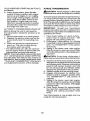
engine, read and understand this manual.
IMPORTANT:
For answers to your questions
Read and follow all Safety
Rules and Instructions before
about this product, Call:
operating this equipment.
1-800-659-5917
SEARS Craftsman
5 am - 5 pro, Mon-
Help Line
Sat
Gasoline containing up to 10% ethanol (El0) is acceptable for use in this machine.
The use of any gasoline exceeding 10% ethanol (ElO)wiii void the product warranty.
Esta m_quina puede utilizar gasolina con un contenido de hasta el 10% de etanol (Et0).
El uso de una gasolina que supere el 10% de etanol (El0) anulard la garantla del producto.
Sears Brands Management Corporation, Hoffman Estates, IL 60179 U.S.A.
Visit our Craftsman website:www.sears.com!craftsman
*Asra_ed
bytheeng_ns
manufacturer
........
581887396
Warranty .................................................. 2
Safety Rules ............................................ 3
Product Specifications ............................. 6
Assembly/Pre-Operation ......................... 7
Operation ............................................... 13
Maintenance Schedule .......................... 2t
Maintenance ..........................................
21
Service and Adjustments ....................... 26
Storage ..................................................
3I
Troubleshooting
.....................................
32
Sears Service .......................... Back Cover
Craftsman Riding Equipment Warranty
CRAFTSMAN FULL WARRANTY
FOR TWO YEARS from the date of purchase, all non-expendable parts of this riding equipment are
warranted against any defects in material or workmanship. A defective non-expendable part will
receive free in-home repair or replacement if repair is impossible.
FOR FIVE YEARS from the date of purchase, the frame and front axle of this riding equipment are
warranted against any defects in material or workmanship. A defective frame or front axle will receive
free in-home repair or replacement ff repair is impossible.
FOR 90 DAYS from the date of purchase, the battery (an expendable part) of this riding equipment
is warranted against any defects in material or workmanship (our testing proves that it will not hold a
charge), A defective battery will receive free in-home replacement.
ADDITIONAL LIFETIME LIMITED WARRANTY on CAST IRON FRONT AXLE (if equipped)
FOR AS LONG AS IT iS USED by the original owner after the fifth year from the date of purchase, the
cast iron front axle (if equipped) of this riding equipment is warranted against any defects in material or
workmanship. With proof of purchase, a defective cast front axle will receive free in-home replacement.
WARRANTY SERVICE
For warranty coverage details to obtain free repair or replacement, call 1-800-659-5917 or visit the
web site: www.craftsman.com
in all cases above, if part repair or replacement is impossible, the riding equipment will be replaced
free of charge with the same or an equivalent model.
All of the above warranty coverage is void if this riding equipment is ever used while providing
commercial services or if rented to another person.
This warranty covers ONLY defects in material and workmanship. Warranty coverage does NOT
include:
• Expendable parts (except battery) that can wear out from normal use within the warranty period,
including but not limited to blades, spark plugs, air cleaners, belts, and oil filters.
• Standard maintenance servicing, oil changes, or tune-ups.
• Tire replacement or repair caused by punctures from outside objects, such as nails, thorns,
stumps, or glass.
-=_-Tire Orwheeirepiacernent_or repair
improperoperation or ....
maintenance.
• Repairs necessary because of operator abuse, including but not limited to damage caused by
. towing objects beyond the capability of the riding equipment, impacting objects that bend the
frame, axle assembly or crankshaft, or over-speeding the engine.
• Repairs necessary because of operator negligence, including but not limited to, electrical and
mechanical damage caused by improper storage, failure to use the proper grade and amount
of engine oil, failure to keep the deck clear of flammable debris, or failure to maintain the riding
equipment according to the instructions contained in the operator's manual.
• Engine (fuel system) cleaning or repairs caused by fuel determined to be contaminated or oxidized
(stale). In general, fuel should be used within 30 days of its purchase date.
• Normal deterioration and wear of the exterior finishes, or product label replacement.
This warranty gives you specific legal rights, and you may also have other rights which vary from
state to state.
Sears Brands Management
......
Corporation,
Hoffman
Estates,
IL 60179
d_I_DANGER:This cutting machine is capable of amputating hands and feet and
throwing objects, Failure to observe the following safety instructions could result
in serious injury or death.
_IbWARNING: 1n orderto prevent accidental starting when setting up, transporting,
adjusting or making repairs, always disconnect spark plug wire and place wire where
it cannot contact spark plug.
•
Never direct discharged materialtoward
anyone. Avoid discharging material
against a wall or obstruction, Material
may ricochet back toward the operator.
Stop the blades when crossing gravel
surfaces.
_ILWARNING: Do not coast down a hill in • Do not operate machine without the enneutral, you may lose control of the tractor.
tire grass catcher, discharge chute, or
othersafety devices inplace and working,
_I_WARNING: Tow only the attachments
• Slow down before turning,
that are recommended by and comply with
• Never leave a running machine unatspecifications of the manufacturer of your
tended. Always turn off blades, set
tractor. Use common sense when towing.
parkingbrake, stop engine, and remove
Operate only at the lowest possible speed
keys before dismounting.
when on a slope. Too heavy of a load, while
•
Disengage blades when not mowing.
on a slope, is dangerous. Tires can lose
Shut off engine and wait for all parts to
traction with the ground and cause you to
cometo a complete stop before cleaning
lose control of your tractor.
the machine, removing the grass catcher,
or unclogging the discharge chute.
_WARNING:
Engine exhaust, some of
• Operate machine only in daytight or good
itsconstituents, and certain vehicle compoartificial light,
nents contain or emit chemicals known to
° Do not operate the machine while under
the State of California to cause cancer and
the influence of alcohol or drugs.
birth defects or other reproductive harm.
o Watch for traffic when operating near or
_t, WARNING: Battery posts, terminals and
crossing roadways.
related accessories contain lead and lead
• Use extracare when loading or unloading
compounds, chemicals known tothe State of
the machine into a trailer or truck.
California to cause cancer and birth defects
• Always wear eye protection when operator other reproductive harm. Wash hands
ing machine.
after handling.
• Data indicates that operators, age 60
years and above, are involved in a large
I. GENERAL OPERATION
percentage of riding mower-related injuries. These operators should evaluate
• Read, understand,and follow allinstructheir ability to operate the riding mower
tions on the machine and in the manual
safely enoughto protectthemselves and
before starting.
o
'
"
*injury
'
others from senous
......
Dp°r_s°trPUthe?n..
ds °T&Itnn_ep!clenag ...........
" ...Fo!!owthe
manufa._ure[:s iecornmenda_"
.......
ttonforwheel weights or counterweights
of the di schar ge opening at all times,
• Only allow responsible adults, who are
" Keep machine free of grass, leaves or
other debris build-upwhich can touchhot
familiar with the instructions, to operate
exhaust/engine parts and burn, Do not
the machine.
allow the mower to plow leaves or other
• Clear the area of objects such as rocks,
debris which can cause build-up to octoys, wire, etc., which could be picked
cur, Clean any oil or fuel spillage before
up and thrown by the blades.
operating or storing the machine, Allow
• Be sure the area is clear of bystanders
machine to cool before storage,
before operating. Stop machine ifanyone
enters the area,
. Never carry passengers.
• Do not mow inreverse unless absolutely
necessary.Always look down andbehind
before and while backing.
Ii, SLOPE OPERATION
• Keep children out of the mowing area
and inthe watchful care of a responsible
Slopes are a major factor related to loss of
adult other than the operator.
control and tip-over accidents, which can
, Be alert and turn machine off if a child
result in severe injury or death. Operation
enters the area.
on all slopes requires extra caution. If you
° Before and while backing, look behind
cannot back up the slope or ifyou fee] uneasy
and down for small children.
on it, do not mow it.
, Never carry children, even withthe blades
- Mow up and down slopes, not across.
shut off. They mayfall offand be seriously
- Watch for holes, ruts, bumps, rocks, or
injured or interfere with safe machine
other hidden objects. Uneven terrain
operation. Children who have been given
could overturn the machine. Tall grass
can hide obstacles.
rides inthe past may suddenly appear in
the mowing area for another ride and be
• Choose a tow ground speed so that you
run over or backed over bythe machine.
will not have to stop or shift while on the
• Never allow children to olqeratethe maslope.
chine.
• Do not mow on wet grass. Tires may lose
traction.
• Use extra care when approaching blind
corners, shrubs, trees, or other objects
Always keep the machine in gear when
that may block your view of a child.
going down slopes. Do notshiftto neutral
and coast downhill.
IV. TOWING
• Avoid starting, stopping, or turning on a
° Tow only witha machine that has a hitch
slope. Ifthe tires Iosetraction, disengage
designed for towing. Do not attach towed
the blades and proceed slowly straight
equipment except at the hitch point.
down the slope.
• Foltowthe manufacturer's recommenda° Keep all movement on the slopes slow
tionfor weight limits for towed eq uipme nt
and gradual.
Do not make sudden
and towing on slopes.
changes in speed or direction, which
• Never allow children or others in or on
could cause the machine to roll over.
towed equipment,
• Use extra care while operating machine
• On slopes, the weight ofthetowed equipwith grass catchers or other attachments;
ment may cause loss oftraction and loss
they can affect the stability of the maof control.
chine. Do no use on steep slopes.
•
Travel slowly and allow extra distance to
, Do not try to stabilize the machine by
stop.
putting your foot on the ground.
V. SERVICE
° Do not mow near drop-offs, ditches,
or embankments, The machine could
SAFE HANDLING OF GASOLINE
suddenly roll over if a wheel is over the
To avoid personal injury or property damedge or if the edge caves in.
age, use extreme care in handling gasoline.
I!1. CHILDREN
Gasoline is extremely flammable and the
___
vapors are explosive,
WARNING: CHILDRENCAN BE INJURED.........; Exfinguist_ all cigarettesl Cigarsl pipesl .....
BYTHIS EQUIPMENT.The American Acadeand other sources of ignition.
my of Pediatrics recommends that children
• Use only approved gasoline container.
be a minimum of t 2 year of age before op° Never remove gas cap or add fuel with
erating a pedestrian controlled lawn mower
the engine running. Allow engine to cool
and a minimum of 16 years of age before
before refueling.
operating a riding lawn mower.
• Never fuel the machine indoors.
° Never storethe machine orfuel container
Tragic accidents can occur if the operator
is not alert to the presence of children,
where there is an open flame, spark, or
Children are often attracted to the machine
pilot light such as on a water heater or
and the mowing activity. Never assume
other appliances,
• Never fill containers inside a vehicle or
that children will remain where you last
saw them.
• on a truck or trailer bed with plastic liner,
Always place containers on the ground
away from your vehicle when filling.
* Remove
gas-powered
equipment
from ° Nevertamperwith safety devices. Check
thetruckortrailerandrefuel
it onthe
their proper operation regularly.
ground.
Ifthisisnotpossible,
thenrefuel • Keep machine free of grass, leaves, or
suchequipmentwith
aportablecontainer,other debris build-up. Clean oil or fuel
rather
thanfroma gasoline
dispenser spillage and remove any fuel-soaked denozzle.
bris. Allow machineto cool beforestoring.
. Keep
thenozzle
incontact
withtherim • If you strike a foreign object, stop and
inspectthe machine. Repair,if necessary,
ofthefueltankorcontainer
opening
at
alltimes
until
fueling
iscomplete.
Donot
before restarting.
• Never make any adjustments or repairs
useanozzle
lock-open
device.
• lffuelisspilled
onclothing,
change
cloth- with the engine running.
• Check grass catcher components and the
ingimmediately.
discharge chute frequently and replace
• Never
overfill
fueltank.
Replace
gascap
with manufacturer's recommended parts,
andtighten
securely.
GENERAL SERVICE
.
•
°
Never operate machine in aclosed area.
Keep all nuts and bolts tightto be sure the
equipment is in safe working condition. - •
when necessary.
Mowerblades are sharp. Wrapthe blade
or wear gloves, and use extra caution
when servicing them.
Check brake operation frequently. Adjust
and service as required.
. Be alert and turn machine off if a child
Maintain or replace safety and instruction
enters the area.
labels, as necessary.
• Before and while backing, look behind
• Be sure the area is clear of bystanders
and down for small children.
before operating. Stop machine if anyone
enters the area.
• Mow up and down slopes (15° Max), not
across.
• Never carry passengers.
• Choose alow ground speed so that you
• Do not mowin reverse unless absolutely
will not have to stop or shift while on the
necessary. Always look down and behind
slope,
before and while backing.
• Avoid starting, stopping, or turning on a
• Never carry children, even with the
slope. Ifthetires Iosetraction, disengage
blades shut off, They may fall off and
............
beseriouslyinjuredotinterfeCewithSa.fe ...................
the blades and proceed slowly straight
machine operation. Children who have
down the slope.
• If machine stops while going uphill,
been given rides inthe past maysuddenly
disengage blades, shift into reverse and
appear in the mowing area for another
back down slowly.
ride and be run over or backed over by
the machine.
• Do not turn on slopes unless necessary,
and then, turn slowly and gradually
Keep children out of the mowing area
and inthe watchful care of a responsible
downhill, [f possible.
° When loading or unloading this machine,
adult other than the operator.
do not exceed the maximum recommended operation angle of 15°.
•
PRODUCT
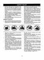
In the state of Californiathe above is required
by law (Section 4442 of the California Public
Resources Code). Other states may have
similar laws, Federal laws apply on federal
lands. A spark arrestor for the muffler is
ava ablethrough your nearest Sears service
center (See REPAIR PARTS manual).
SPECIFICATIONS
Gasoline Capacity
and type:
3.0 Gal_ons!t 1,35 L
Regular Unleaded
Oil Type;
API: SG-SL)
SAE30
(above
32°F/0°C
SAE 5W30 (below 32_F/0°0
Oi} Capacity:
Wl Fitter:
W/out Filter:
Spark Plug:
Champion QC12YC
(Gap: ,040"/1,02 ram)
Charging
System:
1S Amps @3600 RPM
Battery:
AmpiHr:
Min, CCA:
Case size:
Blade Bolt Torque:
45-55 Ft. Lbs./62-75
54 Oz./1.95 L
80 Oz./1.77 L
REPAIR PROTECTION AGREEMENTS
Congratulations on making a smart purchase, Your new Craftsman@ product is
designed and manufactured for years of
dependable operation, But like all products,
itmay require repair from timetotime, That's
when having a Repair Protection Agreement
can save you money and aggravation.
Purchase a Repair Protection Agreement
now and protect yourself from unexpected
hassle and expense.
28
230
U1R
Nm
CONGRATULATIONS onyour purchase of
a new tractor, It has been designed, engineered and manufacturedto giveyou the best
possible dependability and performance.
Should you experience any problem you cannot easily remedy, please contact a Sears or
other qualified service center. We have competent, well-trained representatives and the
proper tools to service or repair this tractor.
Please read and retain this manual. The
instructions will enable you to assemble
and maintain your tractor properly. Always
observe the 'SAFETY RULES".
CUSTOMER
Here's what's included in the Agreement:
RESPONSIBILITIES
°
Expert service byour 12,000 professionaI
repair specialists.
*
Unlimited service and no charge for parts
and labor on all covered repairs.
•
Product replacement if your covered
product can't be fixed.
,
Discount of 10% from regular price of
service and service-related parts not
covered by the agreement; also, 10% off
regular price of preventive maintenance
check.
• Read and observe the safety rules.
, Follow a regular schedule in maintaining,
• Fast help by phone - phone support
caring for and using your tractor.
from a Sears representative on products
• Follow instructions under "Maintenance"
requiring in-home repair, plus convenient
and "Storage '_sections of this manual.
repair scheduling.
• Wear proper Personal Protective EquipOnce you purchase the Agreement, a simple
ment (PPE) while operating this machine,
phone call is allthat ittakes for youto schedincluding (at a minimum) sturdy footwear,
ule seNice. Youcan call anytime day or night,
eye protection, and hearing protection.
or schedule a service appointment online.
Do not mow in shorts and/or open toed
footwear.
Sears has over 12,000 professional repair
-LAIways letsomeoneknowyouareoutside .............
specialists, who have access to over 4.5 ....
million quality parts and accessories. That's
mowing.
the kind of professionalismyou can count on
_,WARNING: This tractoris equipped with
to help prolong the life of your new purchase
an internal combustion engine and should
for years to come. Purchase your Repair
not be used on or near any unimproved Protection Agreement today!
forest-covered, brush-covered or grassSome limitations and exclusions apply.
covered land unless the engine's exhaust
For prices and additional information call
system is equipped with a spark arrestor
1-800-827-6655,
meeting applicable local or state laws (if
SEARS INSTALLATION SERVICE
any), If a spark arrestor is used, it should
be maintained in effective working order by
For Sears professional installation of home
the operator.
appliances, garage door openers, water
heaters, and other major home items, inthe
U.S.A. call 1-800-4-MY-HOME@
6
i iiiii
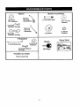
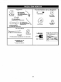
11,
11,
Mower
Mower
i
Front Wheel
©
(2) Rear __
O,D,
Washers
(5) 1-3/t6
Lift Link
_}
Assemblies
_-_
(1) Shoulder Bolt
(1) 1-1/40.D,
Washer
W
(1) Small _@
Retainer Springs
(1) Front
Lift Link
_\
Assembly
"<_._
\_
(1) 3/s-16
(1) Wheel
Locknut
Retainer Springs
11,1,
Slope Sheet
If Equipped
(1) Anti-Sway Bar
Keys
(1) 3/40,D,
Washers
(1) Small Retainer
Springs
*Installed by Dealer
*BrushGuardKit
,,,
(2) Keys
i
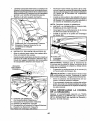
Your new tractor has been assembled at the factory with exception of those parts left unassembled for shipping purposes. To ensure safe and proper operation of your tractor all parts
and hardware you assemble must be tightened securely. Use the correct tools as necessary
to ensure proper tightness.
TOOLS REQUIRED
FOR ASSEMBLY
•
Release lever to lock seat in position.
A socket wrench set will make assembly
easier. Standard wrench sizes are listed.
(2) 7/16" wrenches
Utility knife
(1) 1/2" wrench
(1) 3/4" wrench
Tire pressure gauge
Pliers
(f) 3/4" socket w!drive ratchet
(1) 9/16" wrench
Flashlight
When right or left hand is mentioned in this
" manual, it means when you are in the operating
position (seated behind the steering wheel).
TO
REMOVE
CARTON
UNPACK
•
•
•
•
TRACTOR
FROM
CARTON
Remove allaccessible loose parts and parts
cartons from carton.
Cut along dotted lines on all four panels of
carton. Remove end panels and lay side
panels flat.
Remove mower and packing materials.
Check for any additional loose parts or
cartons and remove.
BEFORE
FROM
REMOVING
TRACTOR
SKID
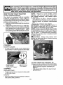
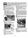
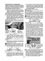
TO CHECK
BATTERY
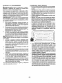
1. Lift hood to raised position,
NOTE: if this battery is put into service after
month and year indicated on label (label is
located between terminals) charge battery
for minimum of one hour at 6-10 amps, (See
"BATTERY" in Maintenance section of this
manual for charging instructions).
.
•
For battery & battery cable installation see
..........................
"REPLACING BATI'ERY" in the "Service
and Adjustments" section in this manual.
Label
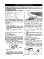
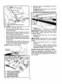
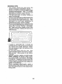
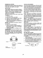
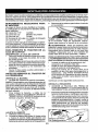
TO ADJUST SEAT
• Sit in seat.
•
Uft up adjustment lever (A) and slide seat
until acomfortable position is reached which
allows you to press clutch/brake pedal all
the way down.
NOTE: You may now roll your tractor off the
skid. Follow the appropriate instruction below
to remove the tractor from the skid.
_, WARNING: Before starting, read, understand and follow all instructions in the Operation
section of this manual. Be sure tractor is in a
well-ventilated area. Be sure the area in front
of tractor is clear of other people and objects.
TO ROLL
Operation
TRACTOR
section
OFF SKID
for location
(See
and
function
of controls)
1. Raise attachment lift lever to its highest
position.
2. Release parking brake bydepressing brake
pedal.
3. Place freewheel control in disengaged position to disengage transmission (See "TO
TRANSPORT" in the Operation section of
this manual).
4. Roll trastorforward
off skid.
Continue with the instructions that follow.
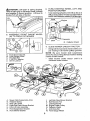
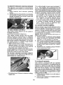
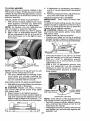
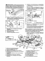
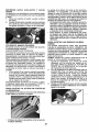
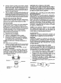
TO INSTALL
MOWER
1. SET PARKING BRAKE LEVER AND
LOWER ATTACHMENT LIFT LEVER
:Depress
clutch!brake Pedal all the way.......
down and hold.
* Pullparkingbrake]everupandhold,
release
pressure from clutch/brake pedal, then
release parking brake lever. Pedal should
remain in brake position. Ensure parking
brake will hold tractor secure.
_CAUTION:
Lift lever is spring loaded,
Have a tightgrip on lift lever, lower it slowly
and engage in lowest position, Lift lever is
located on left side of fender,
3. TURN STEERING WHEEL LEFT AND
POSITION MOWER
* Turn steering wheel to the left as far as it
willgo and position mower on rightside of
tractorwith deflectorshield (Q)tothe right,
Lift
Lever
2,
ASSEMBLE
Front
FRONT
(W) TO FRONT
GAUGE
WHEEL
OF MOWER
Transaxle
Q. Deflector Shield
H.
W.
X.
Y.
Z.
A.
B.
C.
D.
E,
E
H.
Front Mower Bracket
Front Gauge Wheel
Shoulder Bolt
1-1/40.D. Washer
318-16 Locknut
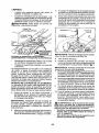
4. SLIDE MOWER UNDER TRACTOR
• Bring beltforwardand check beltforproper routing in all mower pulley grooves.
NOTE: Be sure mower side suspension
arms (A) are pointing forward before sliding
mower under tractor.
° Slide mower under tractor until it is
centered under tractor.
Mower Side Suspension Arms
Retainer Spring
Rear Lift Link(S)
Right Side Rear Mower Bracket
Front Lift Link Assembly
Front Suspension Bracket
Front Mower Bracket
I.
K.
L
M.
Q.
S.
W,
Left Side Rear Mower Bracket
Belt Tension Rod
Locking Bracket
Engine Clutch Pulley
Deflector Shield
Anti-Sway Bar
Front Gauge Wheel
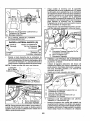
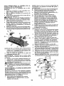
•
•
Pivot the integrated washer end of antisway bar IS)towards mower deck bracket
on right side of mower. Insert integrated
washer end of bar into hole inrear mower
bracket (D), Move mower as needed to
insert integrated washer end of bar into
rear mower bracket (D).
Secure with small washer and small
retainer spring as shown,
A. MowerSide SusaensionArms
Q, DeflectorShield
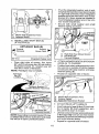
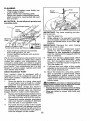
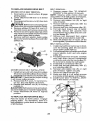
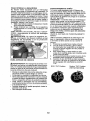
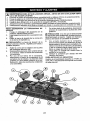
5. INSTALL ANTI-SWAY BAR IS)
(IF EQUIPPED)
_
ANTI-SWAY
Towards
Transaxle
90° End
•
BAR IS)
Towards
Mower Deck _1_
D. Right SideRear MowerBracket
S. Anti-SwayBar
T TransaxleBracket
IntegratedWasherEnd
l"
From right side of mower, first insert
90 ° end of anti-sway bar IS) into hole in
transaxle bracket IT), located near Ieft
rear tire in front of transaxle.
NOTE: Flashlight may be helpful.
Anti-Sway
Bar IS)
Location,,,
_'t
i_
.............. r
6, ATTACH MOWER SIDE SUSPENSION
ARMS (A) TO CHASSIS
• Positionfront hole inside suspension arm
(A) over pin on outside of tractor chassis
and secure with large washer and large
retainer spring (B),
• Repeat on opposite side of tractor.
f)
_x,,_y..................",,
U'! i
I_
\
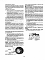
7. ATTACH REAR LIFT LINKS (C)
Insert rod end of rear lift link (C) into hole
(U) in tractor lift shaft suspension arm
and pivot link down to mower.
Liftrear corner of mower and position slot
in link assembly over pin on rear mower
bracket (D) andsecure with large washer
and large retainer spring.
• Repeat on opposite side of tractor,
NOTE: Depending on model, bracket (_ may
be differentthan shown but hole for anti-sway
bar will be in same position/location,
10
9
°
-
8
•
ATTACH FRONT LINK (E)
]3Jrn steering wheel to position wheels
straight forward.
• From front of tractor, insert rod end of
front link (E) through front hole in tractor
front suspension bracket (F).
• Movetoleftsideofmower andand insert
large retainer spring (G) through hole in
front link (E) behind front suspension
bracket (F).
Insert other end of link (E) into hole in
front mower bracket (H) and secure with
washer and smalt retainer spring (J).
NOTE: Requires deck lifting.
Front Unk
i
INSTALL BELT ON ENGINE CLUTCH
PULLEY (M)
Disengage belt tension rod (K) from
locking bracket (L).
Install bettonto engine clutch pulley (M).
M.Engine
Clutch Pulley
IMPORTANT: Check belt for proper routing
in all mower pulley grooves and under
mandrel covers.
• Engage belt tension rod (K) on locking
bracket (L).
_ICAUT!ON:
Belt tension rod is spring
foaded. Have atight grip on rod and engage
slowly.
• Raise attachment lift lever to highest
position.
• If necessary, adjust gauge wheels
before operating mower as shown inthe
Operation section of this manual.
MOWER DRIVE BELT INSTALLATION
Follow procedure
described
in "TO
REPLACE MOWER BLADE DRIVE BELT"
in the "Service and Adjustments" section of
this manual.
._..... ' / .......... "\
1!
CHECK TIRE PRESSURE
The tires on your tractor were overinflated
at the factory for shipping purposes. Correct tire pressure is important for 6est
cutting performance.
o Reduce tire pressure to PSI shown on
tires.
_CHECKLIST
Before you operate your new tractor, we
wish to assure that you receive the best
performance and satisfaction from this
Quality Product,
Please review the following checklist:
d" All assembly instructions have been
completed.
J" No remaining loose parts in carton.
J" Battery is properly prepared and
charged,
J Seat is adjusted comfortably and tightened securely.
J All tires are properly inflated. (For shipping purposes, the tires were overinflated
at the factory).
v/ Be sure mower deck is properly leveled
side-to-side/front-to-rear for best cutting
results. (Tires must be properly inflated
for leveling).
J Check mower and drive belts. Be sure
they are routed properly around pulleys
and inside all belt keepers.
vt Check wiring. See that all connections
are still secure and wires are properly
clamped,
_" Before driving tractor, be sure freewheel
control is in"transmission engaged" position (see "To Transport" in the Operation
section of this manual).
CHECK DECK LEVELNESS
For best cutting results, mower housing
should be properly leveled. See "TO
LEVEL MOWER" in the Service and Adjustments section of this manual.
CHECK FOR PROPER
OF ALL BELTS
POSITION
See the figures that are shown for replacing motion and mower blade drive belts
in the Service and Adjustments section
of this manual. Verify that the belts are
routed correctly.
CHECK BRAKE SYSTEM
After you learn how to operate your tractor, check to see that the brake is operating properly, See "TO CHECK BRAKE"
in the Service and Adjustments section of
this manual.
While learning howto use your tractor, pay
extra attention to the following important
items:
J" Engine oil is at proper level,
v/ Fueltank is filledwith fresh, clean, regular
unleaded gasoline.
!/" Become familiar with all controls, their
location and function. Operate them
before you start the eng!_ne_
...............................
-Z-Besure brake sys:temiS insafe operating
condition,
Be sure Operator Presence System and
Reverse Operation System (ROS) are
working properly (See the Operation and
Maintenance sections in this manual).
d" it is important to purge the transmission
before operating your tractor for the first
time. Follow proper starting and transmission purging instructions (See "TO
START ENGINE" and "PURGE TRANSMISSION" in the Operation section ofthis
manual).
12
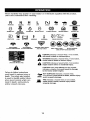
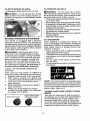
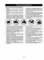
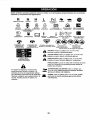
These symbols may appear on your tractor or in literature supplied with the product.
Learn and understand their meaning.
R
N
REVERSE
H
NEUTRAL
I'-.!
L
HIGH
LOW
CHOKE
SLOW
FAST
lnNmON
i.mt
ENGINE
OFF
LIGHTS
ON
REVERSE
OPERATION
SYSTEM
(ROS)
FUEL
ATTACHMENT
CLUTCH
DISENGAGED
ENGINE
BATTERY
ON
ENGINE
REVERSE
ATTACHMENT
CLUTCH
ENGAGED
START
PARKING
FORWARD
DANGER,
KEEP HANDS
AND FEET AWAY
BRAKE
CRUISE
KEEP
MOWER
HEIGHT
CLEAR
(SEE
SAFETY
MOWER
LIFT
CLUTCWBRAKE
PEDAL
CONTROL
AREA
SWITCH
SLOPE
RULES
HAZARDS
SECTION)
DANGER
will
result indicates
in death aorhazard
seriouswhich,
injury,if not avoided,
FREE WHEEL
(Automatts Models only)
WARNING
hazard
which,
if not avoided,
could resultindicates
in deatha or
serious
injury.
CAUTION
indicates
a hazard
which, injury.
if not avoided,
might result
in minor
or moderate
CAUTION when used without the alert Symbol,
indicates a situation that could result in damage
to the tractor and/or engine.
Failure to follow instructions
could result in serious injury or
death. The safety alert symbol
is used to identify safety information about hazards which can
result in death, serious injury
and!or oroDertv damaae.
HOT SURFACES indicates a hazard which,
,,_,_,_., if not avoided, could result in death, serious injury
•""'-"
and/or property damage.
_'_.41_'J. FIRE indicates e hazard which, if not avoided,
could result in death, serious injury and/or
property damage,
13
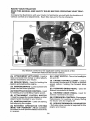
KNOWYOURTRACTOR
READ
THISMANUAL
ANDSAFETY
RULES
BEFORE
OPERATING
YOUR
TRAC-
TOR
Compare the illustrations with your tractor to familiarize yourself with the locationsof
various controls and adjustments. Save this manual for future reference.
Our tractors conform to the applicable safety standards of the
American Natfonal Standards Institute,
(A) ATTACHMENT LIFT LEVER - Used to
rafse and lower the mower or other attach-
(H) LIGHT SWITCH - "SJrns
the headlights
on and off.
ments mounted to your tractor.
(J) CRUISE CONTROL LEVER - Used to
(B) BRAKE PEDAL- Used for braking the
set forward movement of tractor at desired
tracto[_and=sta_t!_gthe engir)e. ..................................
speed without ho!ding the forward _driye
pedal,
(C) PARKING BRAKE- Locksclutch/brake
pedal intothe brake position.
(K) FORWARD DRIVE PEDAL - Used for
forward movement of tractor.
(D) THROTTLE/CHOKE CONTROL- Used
for starting and controlling engine speed.
(L) REVERSE DRIVE PEDAL- Used for
reverse movement oftractor,
(E) ATTACHMENT CLUTCH SWITCH
- Usedto engagethe mower blades, or other
attachments mounted to your tractor.
(M) FREEWHEEL CONTROL- Disengages
transmission for pushing or slowly towing
the tractor with the engine off.
(F) IGNITION SWITCH - Used for starting
and stopping the engine.
(P) SERVICE REMINDER/HOUR METER
- indicates when service is required for the
engine and mower.
(G) REVERSE OPERATION SYSTEM
(ROS) "ON" POSITION - Allows operation
ofmowerorother 3owered attachment while
in reverse,
14
ii
The operation of any tractor can result in foreign objects thrown into
the eyes, which can result in severe eye damage, Always wear safety
glasses or eye shields while operating your tractor or performing any
adjustments or repairs, We recommend standard safety glasses or a
...............
w!de vision safety mask worn over spectacles.
.....
HOW TO USE YOUR TRACTOR
TO SET PARKING BRAKE
Your tractor is equipped with an operator
presence sensing switch. When engine is
running, any attempt bythe operatorto leave
the seat without first setting the parking brake
will shut off the engine.
1. Depress brake pedal (B)alltheway down
and hold.
2, Pull parking brake lever (C) up and hold,
release pressure from brake pedal (B),
then release parking brake lever. Pedal
should remain in brake position. Make
sure parkingbrake will holdtractorsecure,
I
I
|
I
I
NOTE: Failure to move throttle control
between haft and full speed (fast) position, before stopping, may cause engine
to "backfire".
o Turn ignition key (F) to "STOP" position
and remove key. Always remove keywhen
leaving tractor to prevent unauthorized
use.
• Never use choke to stop engine.
IMPORTANT: Leaving the ignitionswitch in
any position other than "STOP" will cause
the battery to discharge and go dead.
NOTE: Undercertain conditionswhentractor
is standing idle with the engine running, hot
engine exhaust gases may cause "browning" of grass. To eliminate this possibility,
always stop engine when stopping tractor
on grass areas.
_JLCAUTION: Always stop tractor completely, as described above, before leaving
the operator's position.
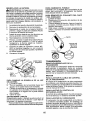
STOPPING
MOWER BLADES • To stop mower blades, push attachment
clutch switch into disengaged position (O).
(I) Attachment
Clutch Switch
Pull Out To "Engage"
TO USE THROTTLE CONTROL (D)
Always operate engine at full speed (fast).
• Operating engine at less than fult speed
(fast) reduces engine's operating efficiency,
• Full speed (fast) offers the best mower
performance.
(O) Push-In to
"Disengaged"
STOPPING
GROUND DRIVE • Tostop ground drive, depress brake pedal
all the way down.
ENGINE • Move throttle control (D) between half and
full speed (fast) position.
15
TO MOVE FORWARD AND BACKWARD
The direction and speed of movement is
controlled by the forward and reverse drive
pedals.
1. Start tractor and release parking
brake.
2. Slowly depress forward (K) or reverse(L)
drive pedal to begin movement, Ground
speed increases the further down the
pedal is depressed.
TO USE CRUISE CONTROL
The cruise control feature can be used for
forward travel only,
SYSTEM CHARACTERISTICS
The cruise control should only be used
while mowing or transporting on relatively
smooth, straight surfaces. Other conditions
such astrimming at stow speeds may cause
the cruise control to disengage. Do not use
the cruise control on slopes, rough tertian
or while trimmimg or turning.
• With forward drive pedal depressed to
desired speed, pull cruise control lever
(J) up and hold while lifting your foot off
the pedal, then release the lever.
Todisengage the cruise control, depress the
brake pedal, tap on forward drive pedal or
push the cruise control tever down,
TO ADJUST MOWER CUTTING HEIGHT
The position of the attachment lift lever (A)
determines the cutting height.
The cutting height range isapproximately 1"
to 4". The heights are measured from the
ground tothe bladetip withthe engine not running.These heights are approximate and may
vary depending uponsoil conditions, height
of grass and types of grass being mowed,
• The average lawn should be cut to approximately 2-t/2" during the cool season and to over 3" during hot months.
For healthier and better looking lawns,
mow Often and after moderate growth.
• For best cutting performance, grass over
6 inches in height should be mowed
twice, Make the first cut relatively high;
the second to desired height.
TO ADJUST GAUGE WHEELS
Gauge wheels are properly adjusted when
they are slightly offthe ground when mower
is at the desired cutting height in operating
position. Gauge wheels then keep the deck
in proper position to help prevent scalping
in most terrain conditions,
NOTE: Adjust gauge wheels with tractor on
a flat level surface.
1, Adjust mower to desired cutting height
(See "TO ADJUST MOWER CUTTING
HEIGHT" in this section of manual).
2. With mower indesired height of cut position, gauge wheels should be assembled
so they are slightly offthe ground, Install
gauge wheel inappropriatehole, Tighten
securely.
3. Repeat for all, installing gauge wheel in
same adjustment hole.
TO OPERATE MOWER
Your tractor is equipped with an operator
presence sensing switch. Any attempt bythe
operator to leave the seat with the engine
running and the attachment clutch engaged
will shut off the engine. You must remain
fully and centrally positioned in the seat to
prevent the engine from hesitating or cutting
offwhen operating your equipment on rough,
rolling terrain or hills.
I. Select desired height of cut with attachment lift lever,
2. Start mower blades by engaging attachment clutch control,
. Put attachment liftlever in desired cutting
height slot.
16
TO STOP MOWER BLADES • Disengage attachment clutch control.
_CAUTION:
Do not operate the mower
without either the entire grass catcher, on
mowers so equipped, orthe deflector shield
(S) in place.
REVERSE OPERATION SYSTEM (ROS)
Your tractor is equipped with a Reverse
Operation System (ROS). Any attempt by
the operator to travel in the reverse direction
withthe attachment clutch engaged willshut
off the engine unless ignition key is placed
in the ROS "ON" position.
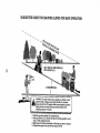
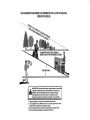
TO OPERATE ON HILLS
_WARNING:
Do not drive up or down
hills with slopes greater than 15° and do not
drive across any slope, Use the slope guide
provided at the back of this manual,
• Choose the slowest speed before starting
up or down hills.
. Avoidstopping or changingspeed on hills.
• If stopping is absolutely necessary, push
brake pedal quickly to brake position and
engage parking brake.
o Torestart movement, slowlyrelease parking brake and brake pedal.
• Slowly depress appropriate drive pedal to
slowest setting.
• Make all turns slowly.
TO TRANSPORT
When pushing or towing your tractor, be
sure to disengage transmission by placing
freewheel control in freewheeling position.
Free wheel control is located at the rear
drawbar of tractor.
• Raise attachment lift to highest position
with attachment lift control,
• Pul! freewheel control out and into the slot
and release so it is held inthe disengaged
position.
. Do not push or tow tractor at more than
two (2) MPH.
• To reengage transmission, reverse above
procedure_
_WARNING:
Backing up with the attachment clutch engaged while mowing
is strongly discouraged. Turning the ROS
"ON", to allow reverse operation with the
attachment clutch engaged, should only
be done when the operator decides it is
necessary to reposition the machine with
the attachment engaged, Do not mow in
reverse unless absolutely necessary,
USING THE REVERSE OPERATION
SYSTEM Only use if you are certain no children or
other bystanders willenter the mowing area.
1. Depress brake pedal all the way down,
2, With engine running, turn ignition key
counterclockwise to ROS "ON" position.
3. Look down and behind before and
NOTE: To protect hood from damagewhen
transporting yourtractor on atruck or atrailer,
while backing,
-4,-Slowly depress reverse drive peda{ to..................
besure hood isclosed andsecuredtotractor, .....
Use an appropriate means of tying hood to
start movement.
5. When use of the ROS is no longer
tractor (rope, cord, etc.).
needed, turn the ignition key clockwise
TOWING CARTS AND OTHER ATTACHto engine "ON" position.
MENTS
ROS "ON" Position
Tow only the attachments that are recommended by and comply with specifications
of the man_acturer of your tractor, Use
common sense when towing. Too heavy
of a load, while on a slope, is dangerous.
Tires can lose traction with the ground and
cause you to lose control of your tractor.
Engine "ON" Position
(Normal Operaling}
17
SERVICE REMINDER/HOUR METER
Service reminder shows the total number of
hours the engine has run and indicates when
the engine or mower needs servicing. After
every 50 hours of operation the oil can icon
will stay on for 2 hours or until a manual reset
occurs. To reset the display manually turn
the ignition switch to the on position, then
the off position five times (! second on, 1
second off). To service engine and mower,
seethe Maintenance section of this manual•
Note: Service reminder runs when the
ignition key is in any position but "STOP",
For accurate reading, be sure key remains
in the "STOP" position when engine is not
running,
BEFORE STARTING THE ENGINE
CHECK ENGINE OIL LEVEL
The engine in your tractor has been
shipped, from the factory, already filled
with summer weight oil,
t. Check engine oil with tractor on level
ground.
2. Remove oil fill cap/dipstick and wipe
clean, reinsert the dipstick and screw
cap tight, wait for a few seconds, remove and read oil level. If necessary,
add oil until "FULE' mark on dipstick is
reached. Do not overfill,
* For cold weather operation you should
change oil for easier starting (See the
oil viscosity chart in the Maintenance
section of this manual).
. To change engine oil, see the Maintenance section in this manual.
- Fill fuel tank to bottom of filler neck. Do
not overfill. Use fresh, clean, regular
unleaded gasoline with a minimum of
87 octane. (Use of leaded gasoline will
increase carbon and lead oxide deposits
and reduce valve life). Do not mix oil
with gasoline. Purchase fuel in quanti.............................................................
ties tf_at can 5e used witRln 30 _ays to
assure fuel freshness.
CAUTION: Wipe off any spilled oil or
• Do not store, spill or use gasoline
near an open flame,
IMPORTANT: When operating in temperatures below 32°F(0°C), use fresh, clean
winter grade gasoline to help insure good
cold weather starting.
I8
CAUTION: Alcohol blended fuels (called
gasoho[ or using ethanol or methanol) can
attract moisture which leads to separation
and formation of acids during storage.
Acidic gas can damage the fuel system
of an engine while in storage, To avoid
engine problems, the fuel system should
be emptied before storage of 30 days
or longer. Drain the gas tank, start the
engine and let it run until the fuel lines
and carburetor are empty. Use fresh fuel
next season. See Storage instructions for
additional information. Never use engine
or carburetor cleaner products in the fuel
tank or permanent damage may occur.
TO START ENGINE
When starting the engine for the first time
or if the engine has run out of fuel, it will
take extra cranking time to move fuel from
the tank to the engine.
1. Be sure freewheel control is in the
transmission engaged position.
2. Sit on seat in operating position,
depress brake pedal and set parking
brake.
3. Move attachment clutch to disengaged
position.
4. Move throttle control to choke position.
NOTE: Before starting, read the warm
and cold starting procedures below,
5, Insert key into ignition and turn key
clockwise to start position and release
key as soon as engine starts. Do not
run starter continuously for more than
fifteen seconds per minute. If the
engine does not start after several
attempts, move throttle control to fast
position, wait a few minutes and try
again. If engine still does not start,
move the throttle control back to the
choke position and retry.
WARM WEATHER STARTING
(50 FI( .......................................
0 C) and above)
6. When engine starts, move the throttle
control to the fast position.
• The attachments and ground drive can
now be used. tf the engine does not
accept the load, restart the engine and
allow it to warm up for one minute using
the choke as described above.
COLD WEATHER STARTING (50°F(10°C)
and below)
6. When engine starts, leave throttle
control in choke position until engine
warms up and begins to run roughly.
Once rough running begins, immediately move the throttle control to the
fast position. Engine warm-up may
take from several seconds to several
minutes (the colder the temperature,
the longer the warm-up).
AUTOMATIC TRANSMISSION WARM UP
Before driving the unit in cold weather,
the transmission should be warmed up as
follows:
1. Be sure the tractor is on level ground.
2. Release the parking brake and let the
brake slowly return to operating position.
3. Allow one minute for transmission to
warm up. This can be done during
the engine warm up period.
The attachments can also be used during the engine warm-up period after the
transmission has been warmed up.
NOTE: Ifata high altitude (above 3000 feet)
or in cold temperatures (below 32°F(0°C))
the carburetor fuel mixture may need to be
adjusted for best engine performance (see
"TO ADJUST CARBURETOR" inthe Service
and Adjustments section of this manual).
PURGE TRANSMISSION
_ILCAUTION: Never engage or disengage
freewheel lever while the engine is running.
Toensure proper operation and performance,
it is recommended that the transmission be
purged before operating tractor for the first
time. This procedure will remove anytrapped
air inside the transmission which may have
developed during shipping of your tractor.
IMPORTANT: Should your transmission
require removal for service or replacement,
it should be purged after reinstallation before
operating the tractor.
1, Place tractor safely on a level surface that is clear of objects and open - with
engine off and parking brake set.
2. Disengage transmission
by placing
freewheel control in disengaged position
(See "TO TRANSPORT" in this section
of manual).
3. Sitting in the tractor seat, start engine.
After the engine isrunning, move throttle
control to slow position. Disengage parking brake.
,_CAUTION:
At any time, during step 4,
there may be movement of the drive wheels.
4. Depress forward drive pedal to full forward position and hold forfive (5)seconds
and release pedal. Depress reverse drive
pedal to full reverse position and hold
for five (5) seconds and release pedal.
Repeat this procedure three (3) times.
5. Shutoff engine and set parking brake.
6. Engage transmission by placing freewheel control in engaged position (See
"TO TRANSPORT" in this section of
manual).
7. Sitting in the tractor seat, start engine.
After the engine isrunning, move throttle
control to haft (i/2) speed. Disengage
........parking brake; ...................................................
...........................
8. Drive tractor forward for approximately
five feet then backwards for five feet.
Repeat this driving procedure three
times.
Your transmission is now purged and now
ready for normal operation.
19
MOWING TIPS
- Tire chains cannot be used when the
mower housing is attached to tractor.
• Mower should be properly leveled for best
mowing performance. See "TO LEVEL
MOWER HOUSING" in the Service and
Adjustments section of this manual.
• The left hand side of mower should be
used for trimming.
• Drive sothat clippings are discharged onto
the area that has already been cut, Have
the cut areato the right ofthetractor. This
will result in a more even distribution of
clippings and more uniform cutting.
• When mowing large areas, start byturning
to the right so that clippings will discharge
away from shrubs, fences, driveways,
etc. After one or two rounds, mow inthe
opposite direction making left hand turns
until finished.
• If grass is extremely tall, it should be
mowed twice to reduce load and possible
fire hazard from dried clippings. Make
first cut relatively high; the second to the
desired height.
. Do not mow grass when it is wet. Wet
grass will plug mower and leave undesirable clumps. Allow grass to dry before
mowing,
• Always operate engine at full throttle
when mowing to assure better mowing performance and proper discharge
--of material: Regulate ground speedby
selecting a low enough speed to give the
mower cutting performance as welt asthe
quality of cut desired.
• When operating attachments, select a
ground speed that will suit the terrain and
give best performance of the attachment
being used.
20
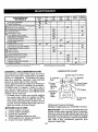
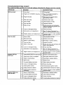
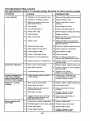
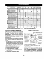
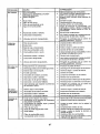
MAINT E NANCE
SCHEDULE
T
A
C
,,,,,,
I_ACH
ii
Operation
Check
Brake
Check
T_te Pressure
==Pc.= _sRv
use
.ou.s
iV
V
B
'
V
_
If
eveRY _Rv
_VERV _V_RY e_OnE
.OURS .OUAS .OURS
25
50
tO0
nl
SEASON
STORAGe
ii
Check Op"rator Presence & ROS Systems
Check for Loose,,Fasteners
i Check/Replace
Mower
Blades
_
....
'
T
Lubrication Chart
If
0
Check
1_4
R
Clean Battery and Terminals
Batte_
Level
Transe×le
Check
Mower
Check
V-BsII_
Chae_e
....
V"
,
0[I
Engine
Change
Level
OIl (with
Cleric
Air
G
C_een
Air Screen
I
Inspect
N
Replace
oiI filter)
E
Clean
eli filter)
FiIter
I
If
,
I
If
.....
L*_'t,2
_i.2
V_
'
If
V';_
Filter
En,gine
,
_
Muffler/Spark
eli
HH
If
En_llne Oil (without
Arrester
(If equipped)
Cooling
Replace
Spark
Replace
Air" Filter
ReDIace
Ik/s
Co,cling
LeveIness
ChEeck Engine
If
Ik/
Clean Debris Off Steering Plate
Check
If
, _'s
Plug
_
....
Fins
{k #12
,
If
Paper Carlridge
FueI Pi_ter
"
......
,,
V"
, _;_
If
,,
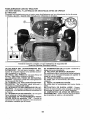
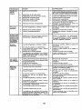
LUBRICATION CHART
GENERAL RECOMMENDATIONS
The warranty on thistractordoes notcover
(_Steering Pivot BoIts
items that have been subjected to operator
abuse or negligence. To receive full
value
(_
Spindle
Zerk
from the warranty, operator must maintain
Zerk
tractor as instructedin this manual.
Front Wheel
Some adjustments will need to be made peBearing Zerk
riodically to properly maintain your tractor.
Wheel
At least once a season, check to see if
Bearing
Zerk
you should make any of the adjustments
Engine
described in the Service and Adjustments
_)Steerir
7secti6n
ofthismanual: ..................................................................................................
Sector.............
I
• At least once a year you should replace
Gear
the spark plug, clean or replace air filter,
Teeth
Mandrel
and check blades and belts for wear. A
Zerks
new spark plug and clean air filter assure
proper air-fuel mixture and help your en(_General Purpose Grease
gine run better and last longer,
(_Refer to Maintenance "ENGINE" Section.
BEFORE EACH USE
IMPORTANT: Do notoilor greasethe pivot
1. Check engine oil level.
points which have special nylon bearings.
2. Check brake operation.
Viscous lubricants wilt attract dust and dirt
3. Check tire pressure.
that will shorten the life of the self-lubricating
4, Check operator presence and
bearings. Ifyou feel they must be lubricated,
ROS systems for proper operation.
use only a dry, powdered graphite type
5. Check for loose fasteners.
lubricantsparingly.
21
TRACTOR
CHECK REVERSE OPERATION (ROS)
SYSTEM
Always observe safety rules when per_
forming any maintenance.
• When the engine is running with the
BRAKE OPERATION
ignitionswitch in the engine "ON" position and the attachment clutch engaged,
If tractor requires more than five (6) feet to
any attempt by the operator to shift into
stop at highest speed in highest gear on a
reverse should shut off the engine.
level, dry concrete or paved surface, then
• When the engine is running with the
brake must be serviced, (See "TO CHECK
ignition switch in the ROS "ON" position
BRAKE" in the Service and Adjustments
and the attachment clutch engaged,
section of this manual).
any attempt by the operator to shift into
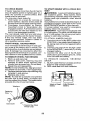
TIRES
reverse should NOT shut off the engine.
• Maintain proper air pressure in all tires
BLADE CARE
(See PSi on tires).
For best results mower blades must be
• Keep tires free of gasoline, oil, or insect
control chemicals which can harm rubsharp. Replace worn, bent or damaged
blades.
ber,
_k CAUTION: Use only a replacement
• Avoid stumps, stones, deep ruts, sharp
blade approved by the manufacturer of
objects and other hazards that may
your tractor. Using a blade notapproved
cause tire damage.
bythe manufacturer of yourtractor is
NOTE: To seal tire punctures and prevent
hazardous, could damage your tractor and
flat tires due to slow leaks, tire sealant
void your warranty.
may be purchased from your local parts
dealer. Tire sealant also prevents tire dry
BLADE REMOVAL
rot and corrosion.
1. Raise mower tohighest positionto allow
OPERATOR PRESENCE SYSTEM AND
access to blades.
REVERSE OPERATION SYSTEM (ROS)
NOTE: Protect your hands with gloves and/
or wrap blade with heavy cloth.
Be sure operator presence and reverse
2. Remove blade bolt by turning counteroperation systems are working properly. If
clockwise.
your tractor does not function as de3. lnstalt newbladewithstamped"THISSIDE
scribed, repair the problem immediately.
UP" facing deck and mandrel assembly.
• The engine should not start unless the
IMPORTANT: To ensure proper assembly,
brake pedal is fully depressed, and
the attachment clutch control is in tfie
center hole in blade must align with star on
disengaged position.
mandrel assembly.
4. Install and tighten blade bolt securely
CHECK OPERATOR PRESENCE
(45-55 Ft, Lbs. torque),
SYSTEM
IMPORTANT: Special blade bolt is heat
• When the engine is running, any attreated.
Mandrel
tempt by the operator to leave the seat
Assembly
withoutfirst setting the parking brake
/
should shut off the engine.
BIade
__i
• When the engine is running and the
¢--__
_._x
attachment clutch is engaged, any atBlade8eltL--_._
_,_'_-/_))_
tempt by the operatortoleavethe
seat ........................
(spe,_ial)_
',-_'_-q. _. 6--_
I.........
should shut off the engine,
""_,_4_" ,-_. "_s,a,
• The attachment clutch should never op_ ._ .[ "._'%.._,'_
erate unless the operator is in the seat.
_Jenler
Hole
"_&
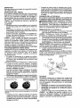
BATTERY
ROS"ON" Position
Engine"ON" Position
(NormalOperating)
Your tractorhas a battery charging system
which is sufficient for normal use. However,
periodic charging of the battery with an automotive charger will extend its life.
• Keep battery and terminals clean.
• Keep battery bolts tight.
° Keep small vent holes open.
• Recharge at 6-10 amperes for 1 hour.
22
NOTE: Although multi-viscosity oils
NOTE: The original equipment battery on
your tractor is maintenance free, Do not (5W30, 10W30 etc.) improve starting in
cold weather, they will result in increased
attempt to open or remove caps or covers.
oil consumption when used above 32°E
Adding or checking level of electrolyte is
Check your engine oil level more frequentnot necessary.
TO CLEAN BATTERY AND TERMINALS
ly to avoid possible engine damage from
running low on oil.
Corrosion and dirt on the battery and terminals can cause the battery to "leak" power. Change the oil after every 50 hours of operation or at least once a year ff the tractor
1. Remove terminal guard.
is not used for 50 hours in one year.
2. Disconnect BLACK battery cable first
Check the crankcase oil level before
then RED battery cable and remove
starting the engine and after each eight
battery from tractor.
3. Rinsethe batterywith plain waterand dry. (8) hours of operation. Tighten oil fill cap/
dipstick securely each time you check the
4. Clean terminals and battery cable ends
oii level.
with wire brush until bright.
5. Coat terminafs with grease or petroleum
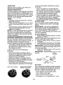
TO CHANGE ENGINE OIL
jelly.
Determine temperature range expected
6. Reinstall battery (See "REPLACING
before oil change, All oil must meet API
BATTERY" in the SERVICE AND ADservice classification SG-SL,
JUSTMENTS section of this manual).
* Be sure tractor is on level surface,
TRANSAXLE MAINTENANCE
- Oil will drain more freely when warm.
Thetransmission fan and cooling fins should
be kept clean to assure proper cooling. Do
° Catch oil in a suitable container.
not attemptto clean fan or transmission while
1. Remove oil fill cap/dipstick, Be careful
engine is running or while the transmission
notto allow dirt to enter the engine when
is hot, Toprevent possible damage to seals,
changing oil.
do not use high pressure water or steam to
2, Slide oi!drain extension fromthe decking
clean transaxle,
position on the engine blower housing
• Inspect cooling fan to be sure fan blades
and extend outward from engine.
are intact and clean.
• Inspectcoolingfins for dirt, grass clippings
Docking
Oil Drain
and other materials. Topreventdamageto
sition
seals, do not use compressed air or high
pressure sprayer to clean cooling fins,
TRANSAXLE PUMP FLUID
The transaxle was sealed atthe factory and
fluid maintenance is not required for the life
of the transaxfe, Should the transaxle ever
leak or require servicing, contact your nearest Sears or other qualified service center.
V-BELTS
Check V-belts for deterioration and wear after
3. To open, twist cap counter-clockwise
t00 hours of operation
and replace !....................
ff neces" ........
...........................................
'......................................
4, .After oil is drained-completely, replace.....
san/. The belts are not adjustable. Replace
cap and twist clockwise until it stops.
belts if they begin to slip from wear.
5. Re-attach oil drain extension to engine
ENGINE
blower housing.
LUBRICATION
6, Refill engine with oilthrough oil fill dipstick
Only use high quality detergent oil rated
tube. Pour slowly, Do not overfill, For apwith APi service classification SG.SL,
proximate capacity see "PRODUCT SPSelect the oil's SAE viscosity grade
ECIFICATIONS" section of this manual.
according to your expected operating
7. Use gauge on oil fill cap/dipstick for
temperature.
checking level. For accurate reading,
tighten dipstick cap securely onto the
tube before removing dipstick. Keep oil
at "FULL:' line on dipstick, Tighten cap
onto the tube securely when finished.
"
23
ENGINE OIL FILTER
Replace the engine oil filter every season or
every other oil change if the tractor is used
more than 100 hours in one year,
AIR FILTER
Your engine will not run properly using a
dirty airfilter. Clean the foam pre-cleaner
after every 25 hours of operation or every
season. Service paper cartridge every
1O0 hours of operation or every season,
whichever occurs first.
Service air cleaner more often under dusty
conditions.
1. Remove cover.
TO SERVICE PRE-CLEANER
2. Wash it in liquid detergent and water.
3. Squeeze it dry in a clean cloth,
4. Saturate it in engine oil Wrap it in
clean, absorbent cloth and squeeze to
remove excess oil.
NOTE: If very dirty" or damaged, replace
pre-cleaner.
TO SERVICE CARTRIDGE
1, Clean cartridge by tapping gently on
flat surface. If very dirty or damaged,
replace cartridge,
2. Reinstall precleaner cartridge, cover
and secure.
IMPORTANT: Petroleum solvents, such
as kerosene, are not to be used to clean
the cartridge. They may cause deterioration of the cartridge. Do not oil cartridge,
Do not use pressurized airto clean or dry
cartridge.
_
CLEAN AIR SCREEN
Air screen must be kept free of dirt and chaff
to prevent engine damage from overheating.
Clean with awire brush or compressed air to
remove dirt and stubborn dried gum fibers.
CLEAN AIR INTAKE/COOLING AREAS
To ensure proper cooling, make sure the
grass screen, cooling fins, and other external surfaces of the engine are kept clean
at all times.
Every 100 hours of operation (more often
under extremely dusty, dirty conditions),
remove the blower housing and othercooling
shrouds. Clean the cooling fins and external
surfaces as necessary. Make sure the cooling
shrouds are reinstalled.
NOTE: Operating the engine with ablocked
grass screen, dirty or plugged cooling fins,
and/or cooling shrouds removed will cause
engine damage due to overheating.
MUFFLER
Inspect and replace corroded muffler and
spark arrester (if equipped) as it could create
a fire hazard and/or damage,
SPARK PLUG(S)
Replace spark plug(s) at the beginning of
each mowing season or after every 100
hours of operation, whichever occurs first.
Spark plug type and gap setting are shown
in "PRODUCT SPECIFICATIONS" section
of this manual.
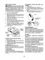
IN-LINE FUEL FILTER
The fuel filter should be replaced once each
season. If fuel filter becomes clogged, obstructing fuel flew to carburetor, replacement
is required.
1. With engine cool, remove filter and plug
fuel line sections.
2. Place newfuelfilter in position in fuel line
with arrow pointing towards carburetor.
3. Be sure there are no fuel line leaks and
..........
_la_psai"eprbpe_ly _pSsitiSi_ed.......................
4, tmmediatelywipe up anyspilled gasoline.
jOartridge
Fuel Filter -------__
Foam
_
I
PreoC[eaner_f_
24
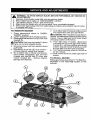
CLEANING
• Clean engine, battery, seat, finish, etc,
of all foreign matter.
• Clean debris from steering plate.
Debris can restrict clutch/brake pedal
shaft movement, causing belt slip and
loss of drive.
Nozzle
Washout
Por_
A CAUTION: Avoid all pinch points and
movable parts
Clutch/brake pedal
Clean
IMPORTANT: Tug hose ensuring connection is secure.
5. Turn the water on.
6. While sitting in the operator's position
Steering
on the tractor, re-start the engine and
place the throttle lever in the Fast "._y"
position.
CAUTION:
IMPORTANT: Recheck the area making
Steering System, Dash,
_&
Pinch
certain the area is clear.
Fender and Mower Not Shown
_
Points
7. Move the tractor's attachment clutch
control to the "ENGAGED" position.
• Keep finished surfaces and wheels
Remain in the operator's position
free of all gasoline, oil, etc.
with the cutting deck engaged until the
• Protect painted surfaces with automodeck is cleaned.
tive type wax.
8. Move the tractor's attachment clutch
We do not recommend using a garden hose
control to the "DISENGAGED" posior pressure washer to clean your tractor
tion. Turn the ignition key to the STOP
unless the engine and transmission are
position to turn the tractor's engine off.
covered to keep water out. Water in engine
Turn the water off.
or transmission will shorten the useful life of
your tractor. Use compressed air or a leaf
9. Pull back the lock collar of the nozzle
blower to remove grass, leaves and trash
adapter to disconnect the adapter from
from tractor and mower.
the nozzle washout port.
DECK WASHOUT PORT
t0. Move the tractor to a dry area, preferably a concrete or paved area. Place
Your tractor's deck is equipped with a
the attachment clutch control in the
washout port on its surface as part of its
"ENGAGED" position to remove excess
deck wash system, tt should be utilized afwater and to help dry before putting the
ter each use.
tractor away.
1. Drive the tractor to a level, clear spot
_WARNING: A brokenor missingwashout
on your lawn, near enough to a water
................
spigot=foryourgarden hose =toreach ............
fltting_could=expose..you=.or
other.s.to_thrownu
IMPORTANT: Make certain the tractor's
objects from contactwith the blade.
discharge chute is directed AWAYfromyour
• Replacebrokenor missing washoutfiffing
house, garage, parked cars, etc. Remove
immediately,priorto usingmoweragain.
bagger chute or mulch cover if attached.
• Plug
any holes in mower with bolts and
Iocknuts.
2. Make sure the attachment clutch control
is in the "DISENGAGED" position, set
the parking brake, and stop the engine.
3. Thread the nozzle adapter (packaged
with your tractor's Operator's Manual)
onto the end of your garden hose.
4. Pull back the lock collar of the nozzle
adapter and push the adapter onto the
deck washout port atthe [eft end of the
mower deck. Release the lock collar to
lock the adapter on the nozzle.
25
,_
1.
3.
4.
5,
6,
WARNtNG:
TO AVOIDSERIOUSINJURY,BEFOREPERFORMINGANY SERVICEOR
ADJUSTMENTS:
Depress clutch/brake pedal fully and set parking brake.
Place attachment clutch in "DISENGAGED" position.
Turn ignition key to "STOP" and remove key.
Make sure the blades and all moving parts have completely stopped,
Disconnect spark plug wire from spark plug and place wire where it cannot come
in contact with plug,
TO REMOVE MOWER
t.
Place attachment clutch in "DISENGAGED" position,
2, Lower attachment lift to lowestposition,
3. Disengage belttension rod (K) from lock
bracket (L),
• ILCAUTION: Rod is spring loaded. Have a
tight grip on rod and release slowly,
4, Remove mower belt from electric clutch
pulIey (M).
5. Disconnect front link (E) from mower remove retainer spring and washer,
6, Go to either side of mower and disconnect mower suspension arm (A) from
chassis and rear lift link (C) from rear
mower bracket (D) - remove retainer
springs and washers.
26
7. Go to other side of mower and disconnect
the suspension arm and rear lift link.
_tk CAUTION: After rear lift links are disconnected, the attachment liftleverwitI be spring
loaded. Have a tight grip on lift lever when
changing position of the lever,
8, From right side of mower, disconnect
anti-sway bar (S) from right rear mower
bracket (D) - remove retainerspring and
washer and pull mower toward you until
the bar falls from the hole in bracket.
9. Turn tractor steering wheel to the left as
far as it will go,
10. Slide mower out from under right side of
tractor.
TO INSTALL MOWER
Follow procedure described in"TO INSTALL
MOWER" in the Assembly section of this
manual.
TO LEVEL MOWER
Make sure tires are properly inflated to the
PSi shown on tires. Iftires are over or under
inflated, it may affect the appearance of your
lawn and lead you to think the mower is not
adjusted properly.
VISUAL SIDE-TO-SIDE ADJUSTMENT
1. With all tires properly inflated and ifyour
lawn appears unevenly cut, determine
which side of mower is cutting lower,
NOTE: As desired, you can raise the low
side of mower or lower the high side.
2. Go to side of mower you wish to adjust.
3. With a 3/4" or adjustable wrench, turn
lift link adjustment nut (A) to the left to
lower the mower, or,to the right to raise
the mower.
Turn nut ri
to raise mower
"Pjrn nut left
to lower mower
NOTE: Each full turn of adjustment nut will
change mower height about 3/16".
4. Test your adjustment by mowing some
uncut grass and visually checking the
appearance. Readjust, if necessary, until
you are satisfied with the results.
PRECISION SIDE-TO-SIDE ADJUSTMENT
1. With alltires
on level ground or driveway.
CAUTION: Blades are sharp. Protect
your hands with gloves and/or wrap blade
with heavy cloth.
2. Raise mower to its highest position.
3. At both sides of mower, position blade at
side and measure the distance (A) from
bottom edge of blade to the ground. The
distanceshould bethesameon bothsides.
27
4. ff adjustment is necessary, see steps 2
and 3 in Visual Adjustment instructions
above.
5. Recheck measurements, adjustif necessary' until both sides are equal.
FRONT-TO-BACK ADJUSTMENT
IMPORTANT: Deck must be level sideto-side.
To obtain the best cutting results, the mower
blades should be adjusted so the front tip is
1/8" to 1/2" lower than the rear tip when the
mower is in its highest position.
CAUTION: Blades are sharp. Protect
your hands with gloves and/or wrap blade
with heavy cloth.
• Raise mower to highest position.
- Position any blade so the tip is pointing
straight forward. Measure distance (B) to
the ground atfront and reartip of the blade.
,, Iffronttip of blade is not t/8" to 1/2" lower
than the rear tip, go to the front of tractor.
• With an 11/16" or adjustable wrench,
loosen jam nut A several turns to clear
adjustment nut B.
• With a 3/4" or adjustable wrench, turn
front link adjustment nut {B) clockwise
(Itighten) to raise the front of mower, or,
counterclockwise (loosen) to lower the
front mower.
Tighten adjust nut
B to raise mower
Loosen adjust
nut B to lower
mower
Loosenjam nut A first
NOTE: Each full turn ofthe adjustment nut
will change mower height about 1/8".
• Recheck measurements, adjust if necessary until front tip of blade is 1/8" to 1/2"
lower than the rear tip.
- Holdadjustment nut in position withwrench
and tighten jam nut securely against adjustment nut.
TO REPLACE MOWER DRIVE BELT
MOWER DRIVE BELT REMOVAL
1. Park tractor on a level surface, Engage
parking brake.
2. Lower attachment lift lever to its lowest
position.
3, Disengage belttension rod (K) from lock
_lbracket (L).
AUTION: Belttension rodis spring loaded. Have afirm grip on rod and release slowly,
4. Remove screws (P) from R.H. and L,H.
mandrel covers and remove covers (Q).
5. Remove any dirt or grass clippings which
may have accumulated around mandrels
and entire upper deck surface.
6. Remove belt from electric clutch pulley
(M), both mandrel pulleys (R) and all idler
pulleys (S).
BELT REMOVAL t. Remove mower (See "TO REMOVE
MOWER" in this section of manual).
NOTE: Observe entire motion drive belt
and position of all belt guides and keepers,
2. Disconnect clutch wire harness (A).
3, Remove anti-rotation link (B) on right
side of tractor.
4. Remove belt from stationary idler (C)
and clutching idler (D),
5. Remove bett from centerspan idler (E).
6. Pull belt slack toward rear of tractor,
Carefully remove belt upwards from
transmission input pulley and over cooling fan blades (F),
7, Remove belt downward from engine
pulley and around electric clutch (G).
8, Slide belt toward rear of tractor, off the
steering plate(H) and removefromtractor.
BELT INSTALLATION 1. I nstalt new belt from tractor rear to front,
over the steering plate (H) and above
clutch brake pedal shaft (J).
2. Pull belttowardfront oftractor andr01tbelt
around electric clutch and onto engine
pulley (G).
3, Pull belttoward rear of tractor. Carefully
work belt down around transmission
cooling fan and onto the input pulley (F).
Be sure belt is inside the belt keeper,
4. Install belt on centerspan idler (E).
5. tnstali belt through stationary idler (C)
and clutching idler (D).
6. Reinstall anti-rotation link (B) on right
side of tractor. Tighten securely.
7, Reconnect clutch harness (A).
8. Make sure belt is in all pulley grooves
and inside all belt guides and keepers,
9, Install mower (See "TO INSTALL MOWER" in this section of manual),
MOWER DRIVE BELT INSTALLATION
1, Install belt around both mandrel pulleys
(R) and around idler pulteys (S)as shown.
2. Install beltonto electricclutch pulley (M).
IMPORTANT: Check beltfor proper routing
in all mower pulley grooves.
3, Reassemble R,H, and L.H. mandrel covers (Q). Securely tighten all screws.
._4+_.Engage belt tension rod (K) on locking ................................
bracket (L),
("=_1
& CAUTION: Belt tension rod is spring load_
ed. Have atight gripon rodand engage slowly,
iY',_t I
5. Raise attachment lift lever to highest
_-_"
position,
TO REPLACE MOTION DRIVE BELT
Park the tractor on level surface. Engage
parking brake. For assistance, there is a
belt installation guide decal on bottom side
of left footrest.
"J
28
(_
TO CHECK BRAKE
If tractor requires more than five (5) feet to
stop at highest speed in highest gear on a
level, dr:i concrete or paved surface, then
brake must be serviced.
You may also check brake by:
1. Park tractor on a level, dry concrete or
paved surface, depress brake pedal all
theway down and engage parking brake.
2. Disengage transmission by placing
freewheel control in "transmission disengaged" position. Pullfreewheel control
out and into the slot and release so it is
held in the disengaged position,
The rear wheels must lock and skid when
you try to manually push the tractor forward.
If the rear wheels rotate, then the brake
needs to be serviced, Contact a Sears or
other qualified service center.
FRONT WHEEL TOE-IN/CAMBER
Your new tractor front wheel toe-in and camber is set at the factory and is normal. The
front wheeltoe-in and camber are not adjustable. If damage has occurred to affect the
factory set front wheel toe-in or camber, contact a Sears or other qualified service center.
TO REMOVE WHEEL FOR REPAIRS
1. Block up axle securely.
2. Remove axle cover, retaining ring and
washers to allow wheel removal (rear
wheels have a square key- Do not lose).
3. Repair tire and reassemble.
NOTE: On rearwheels only: align grooves in
rear wheel hub and axle. Insert square key.
4. Replacewashers and snap retainingring
securely in axle groove.
5. Replace axle cover.
NOTE: To seal tire punctures and prevent
flat tires due to slow leaks, purchase and
usetire sealantfrom Sears. Tire sealant also
prevents tire dry rot and corrosion,
Battery
Washers
Retaining
Ring
_le_Oover
TO START ENGINE WITH A WEAK BATTERY
_WARNING:
Lead-acid batteries generate explosive gases. Keep sparks, flame
and smoking materials away from batteries.
Always wear eye protection when around
batteries.
If your battery is too weakto start the engine, it
should be recharged. (See"BATI-ERY" inthe
MAINTENANCE section of this manual).
If "jumper cables" are used for emergency
starting, follow this procedure:
IMPORTANT: Your tractor is equipped with
a 12 volt system. The othervehicle must also
be a 12 volt system. Do not use your tractor
battery to start other vehicles.
TO ATTACH JUMPER CABLES
1. Connect one end ofthe RED cable tothe
POSITIVE (+) terminal of each battery(AB),taking care notto shortagainst tractor
chassis.
2. Connect one end of the BLACK cable
to the NEGATIVE (-) terminal (C) of fully
charged battery.
3. Connect the other end of the BLACK
cable (D) to good chassis ground, away
from fuel tank and battery.
TO REMOVE
CABLES,
REVERSE
ORDER
1. BLACK cable first from chassis and then
from the fu[ly charged battery,
2. RED cable last from both batteries.
I
'_Square
Key(Rear
Wheel Only)
29
Battery
REPLACING BATTERY
n_asWARNING: Do not short battery termiby allowing awrench or any other object
to contact both terminals at the same time.
Before connecting battery, remove metal
bracelets, wristwatch bands, rings, etc.
Positiveterminal must be connected firstto
preventsparkingfrom accidental grounding.
t. Lift hood to raised position.
2. Remove terminal cover.
3. Disconnect BLACK battery cable then
RED battery cable and carefully remove
battery from tractor.
4. Install new battery with terminals insame
position as old battery.
5. Reinstall terminal cover.
6. First connect RED battery cable to positive (+) battery terminal with bolt and nut
as shown. Tighten securely,
7. Connect BLACK grounding cable to
negative(-) batteryterminal with remaining bolt and nut.Tighten securely
8. Close hood.
TO REMOVE HOOD AND GRILL ASSEMBLY
1. Raise hood.
2. Unsnap headlight wire connector,
3. Stand in front of tractor. Grasp hood at
sides, tilt toward engine and lift off of
tractor,
4. When replacing hood, be sure to reconnect the headlight wire connector.
_
H°iladlight Wire
Connector
TRANSMISSION
REMOVAL/REPLACEMENT
Should yourtransmission require removalfor
service or replacement, it should be purged
after reinstallation and before operating the
tractor. See "PURGE TRANSMISSION" in
the Operation section of this manual.
ENGINE
TO ADJUST THROTTLE CONTROL
CABLE
The throttle control has been preset at
TO REPLACE HEADLIGHT BULB
the factory and adjustment should not be
1. Raise hood.
necessary Check adjustment as described
2. Remove bulb holder from the hole inthe
below before loosening cable, If adjustment
is necessary, see engine manual.
backside of the grill.
-3;--Repface-bulb in holder- and instatFbulb .......TO.ADJUST CHOKECONTROL ........................
holder securely back into the hole in the
The choke control has been preset at
backside ofthe grill.
the factory and adjustment should not be
4. Close hood.
necessary. If adjustment is necessary, see
INTERLOCKS AND RELAYS
engine manual.
TO ADJUST CARBURETOR
Loose or damaged wiring may cause your
tractortorun poorly,stop running,orpravent
Yourcarburetor has been presetatthe factory
it from starting.
and adjustment should not be necessary.
• Check wiring.
However, minor adjustment may be required
TO REPLACE FUSE
to compensate for differences in fuel, temperature, altitude or toad. Ifthe engine does
Replace with 30 amp automotive-type plugin fuse. The fuse holder is located behind
need adjustment, see engine manual.
the dash,
30
Immediately prepare your tractor for storage
ENGINE
at the end of the season or if the tractor will FUEL SYSTEM
not be used for 30 days or more.
IMPORTANT: It is important to prevent
,_ILWARNING: Never store the tractor with gum deposits from forming in essential fuel
system parts such as carburetor, fuel hose,
gasoline inthe tank inside a building where
ortank during storage. Also, alcohol blended
fumes may reach an open flame or spark,
Allow the engine to coo! before storing in fuels (called gasohol or using ethanol or
methanol) can attract moisture which leads
any enclosure.
to separation and formation of acids during
TRACTOR
storage. Acidic gas can damage the fuel
Remove mower from tractor for winter
system of an engine while in storage.
storage. When mower is to be stored for a • Emptythe fueltank by starting the engine
period of time, clean it thoroughly, remove
and letting it run until the fuel lines and
all dirt, grease, leaves, etc. Store in a clean,
carburetor are empty.
dry area.
• Never use engine or carburetor cleaner
1. Clean entire tractor (See "CLEANING"
products in the fuel tank or permanent
in the Maintenance section of this
damage may occur.
manual).
- Use fresh fuel next season.
2. Inspect and replace belts, if necessary
NOTE: Fuel stabilizer is an acceptable al(See belt replacement instructions in the ternative in minimizing the formation of fuel
Service and Adjustments section of this
gum deposits during storage. Add stabilizer
manual).
to gasoline in fuel tank or storage container.
3. Lubricate as shown in the Maintenance
Aiways foilowthe mix ratiofound on stabilizer
section of this manual,
container. Run engine at least 10 minutes
4. Be sure that all nuts, bolts and screws
after adding stabilizer to allowthe stabilizerto
are securely fastened. Inspect moving
reach the carburetor. Do not empty the gas
parts for damage, breakage and wear, tank and carburetor if using fuel stabilizer,
Replace if necessary.
ENGINE OIL
5. Touch up all rusted or chipped paint
Drain oil (with engine warm) and replace
surfaces; sand lightly before painting,
with clean engine oil. (See "ENGINE" inthe
BATTER'{
Maintenance section of this manual).
CYLINDER(S)
• Fully charge the battery for storage.
• After a period of time in storage, battery
1. Remove spark plug(s).
may require recharging.
2, Pour one ounce of oil through spark plug
• Tohelp prevent corrosion and power leakhole(s) into cylinder(s),
age during long periods of storage, battery 3. Turn ignition key to "START" position for
cables should be disconnected and bata few seconds to distribute oil.
tery cleaned thoroughly (see "TO CLEAN
4. Replace with new spark plug(s).
BATTERY AND TERMINALS" in the
OTHER
- Maintenance section ofthiS ma_nual):........................................................................................................
o Do not store gasoline from one season to
, After cleaning, leave cables disconnected
another.
and placecables wherethey cannot come
• Replaceyourgasotine can ifyourcan starts
in contact with battery terminals,
to rust, Rust and/or dirt in your gasoline
, If battery is removed from tractor for
will cause problems.
storage, do not store batter/directly on
° tf possible, store your tractor indoors and
concrete or damp surfaces.
cover itto give protection from dustand dirt,
• Cover your tractor with a suitable protective cover that does not retain moisture,
Donot use plastic. Plasticcannotbreathe
which allows condensationto form and will
cause your tractor to rust.
IMPORTANT:
Never cover tractor while
engine and exhaust areas are still warm,
31
TROUBLESHOOTING CHART:
See appropriate section in manual unless directed to Sears service center
PROBLEM
CAUSE
,,,,,,
Will not start
t
Out of fuel.
1
FIII fuel tank.
2
Engine not "CHOKED _ properly.
2
See "TO START ENGINE _ in
Operation section.
3
Engine flooded.
3
Wait several minutes before
attempting to start.
4
Bad spark plug.
4
Replace spark plug.
5
Dirty air filter.
5
Clean!replace
6
Dirty fuel filter.
6
Replace fuel filter.
7
Waterin
8
Loose or damaged wiring.
8
Check all wiring.
9
Carburetor
9
See "To Adjust Carburetor" in
Service and Adjustments section.
Engine valves out of adiustment.
10
Contact s Sears or other qualified
service center.
Dirty air filter.
1
Clean/replace
10
Hardto start
1
2
Engine clacks but
wilt not start
fuel.
,7
out of adjustment.
air filter.
Empty fuel tank and carburetor,
refill tank with fresh gasoline and
replace fuel filter.
air filter.
Bad spark plug,
2
Replace spark plug,
Weak or dead battery.
3
Recharge or replace battery.
4
Dirty fuel tilter.
4
Replace fuel filter.
5
Stale or dirty fuel.
5
Empty fuel tank and refill tank with
fresh, clean gasoline.
6
Loose or damaged wiring.
6
Check all wiring.
7
Carburetor
7
See "To Adjust Carburetor" in
Service and Adjustments section.
8
Engine valves out of adjustment.
8
Contact a Sears or other qualified
sewice center.
1
Clutch/brake
1
Depress clutch!brake
2
Attachment
2
Disengage attachment
3
Weak or dead battery.
3
Recharge or replace battery.
4
=Blown fuse_-................................................................................................................................
4 Replace fuse.
5
Corroded
battery terminals.
5
Clean battery terminals.
6
Loose or damaged wiring.
6
Check all wiring.
7
Faulty ignition switch.
!7
Check/replace
ignition switch.
8
Faulty solenoid or starter.
8
Check/replace
solenoid or starter.
9
Faulty operator presence
switch (as).
9
Contact a Sears or other qualified
service center.
1
Weak or dead battery.
1
Recharge or replace battery.
2
Corroded battery terminals.
2 : Clean battery terminals.
3
Loose or damaged wiring.
3
Check all wiring.
4
Faulty solenoid or starter.
4
Check!replace
i3
Engine will not
turn over
CORRECTION
.........................
out of adjustment.
pedal net depressed
clutch is engaged.
32
pedal.
clutch.
solenoid or starter.
TROUBLESHOOTING CHART:
See appropriate section in manual unless directed to Sears service center
PROSLEM
Loss of power
CAUSE
.............
CORRECTION
1
Cutting too much grass/too fast,
1
Raise cutting height/reduce
2
Throttle in "CHOKE" position.
2
Adjust throttIe control.
speed
3
Build-up of grass, leaves and
trash under mower,
3
Clean underside of mower
housing,
4
Dirty air _ter.
4
Clean/replace
5
Low oil level/dirty oil,
5
Check oil level/change oil,
6
Faulty spark plug.
6
Clean®aporchangesparkplug
7
Dirty fuel filter,
7
Replace fuel filter.
8
Stale or dirty fuel.
8
Empty fuel tank and refill tank witt"
fresh, clean gasoline.
9
Water in fuel.
9
Empty fuel tank and carburetor,
refill tank with fresh gasoline end
replace fuel fiJter,
air filter.
!10
Spark plug wire loose.
10
Connect & tighten spark plug wire.
11
Dirty engine air screen/fins,
11
Clean engine air screen/fins.
12
Dirty/clogged muffler,
12
C[eanireplace
13
Loose or damaged wiring.
13
Check all wiring.
14
Carburetor
14
See 'q'o Adjust Carburetor" in
Service and Adjustments section.
15
Engine valves out of adjustment.
15
Contact a Sears or other qualified
service center.
out of adjustment,
muffler,
,,,,,,.,,,,,,,
....
1
Worn. bent or loose blade.
1
Replace blade. Tighten blade boit,
2
Bent blade mandrel.
2
Contact a Sears or other qualified
service center,
3
Loose/damaged
3
Tighten loose part(s),
Replace damaged parts.
Engine continues to
run when operator
leaves seat with attachment clutch engaged
1
Faulty operator-safety
control system,
I
Check wiring, switches and
connections. If not corrected,
contact a Sears or other
Poorcut - uneven
t
Worn, bent or loose blade.
presence
,,,,,,........
2
1
Replace blade. Tighten blade bolt.
_Mowerdeck_ not IeveI_...............................................
2
Buildup of grass, leaves, and
trash under mower.
3
Clean underside
housing.
Bent blade mandrel.
4
Contact a Sears or other
qualified service center,
Clogged mower deck vent from
build-up of grass, leaves, and
trash around mandrels.
5
Clean around mandrels
open vent holes.
to
,,_,,,_,,, ,,., ,,,
,
1
Obstruction
1
Remove obstruction,
2
Worn/damaged
2.
Replace mower drive belt.
3
Frozen idler pulJey.
3
Replace idler pulley,
4
Frozen blade mandrel,
4
Contact a Sears or other
qualified service center.
3
Mower blades will
not rotate
part(s).
in clutch mechanism,
mower
33
drive belt
of mower
TROUBLESHOOTING
CHART:
See appropriate section in manual unless directed to Sears service center
PROBLEM
'CAUSE
Poor grass
discharge
Headlight(s)
not
working
(if so equipped)
1
Engine speed too slow.
1
Place throttle control in "FAST"
position,
2
Travel speed too fast.
2
Shift to slower speed.
3
Wet grass.
3
Allow grass to dry before mowing
4
Mower deck not level
4
Level mower deck.
5
Low/uneven
5
Check tires for proper PSi.
6
Worn. bent or loose blade.
6
Replace/sharpen
blade bolt.
7
Buildup of grass, leaves and
trash under mower,
7
Clean underside of mower
housing.
8
Mower drive belt worn.
8
Replace mower drive belt.
9
Blades improperly installed.
9
Reinstall blades sharp edge down
tire air pressure.
blade. Tighten
10
Improper blades used.
11
Clogged mower deck vent holes
11
from buildup of grass, leaves, and
trash around mandrels.
Clean around mandrels to
open vent holes.
I
Ught swi'tch is "OFF'.
Turn {ight switch "ON".
2
Bulb(s) or lamp(s) burned out.
2
Replace bulb(s) or lamp(s).
3
Faulty light _tch.
3
Check/rep[ace
4
Loose or damaged wiring.
4
Check wiring and connections.
5
Blown fuse.
5
Replace fuse.
Bad battery cell(s).
1
Replace battery.
2
Poor cable connections.
2
Check/clean
3
Faulty regulator (if so equipped).
3
Rep{ace regulator.
4
Replace alternator.
1
Place freewheel control in
"ENGAGED" position.
,,,,,,,,,,,,,,,,,,,,,,
,
Battery
charge
CORRECTION"'
"10 Replace with blades listed in
thJs manual.
'_
!1
light switch.
,,,,,
will not
1
,,,,
4
Faulty alternator.
_
Freewheel control in
"DISENGAGED" position.
"" ""
all connections.
,_,
Loss of drive
,u,,,
2
Debds on steering plate (if
2. See "CLEANING" in the
..........................................................................................
eciu!pped)_........................................................................................
rDaintenance s_qt!Qn ......................................
3
Motion drive belt worn, damaged,
or broken.
3
Replace motion drive belt.
4
Air trapped in transmission during
shipment or servicing.
4
Purge transmission.
5
Axle key missing.
5
Install axle keyat rear wheel. See
"TO REMOVE WHEEL" in the
Service and Adjustments section.
1
Engine throttle control not se_ I
between half and full speed (fasl
position before stopping engine,
Move throttle control between
half and full speed (fast) position
before stopping engine.
1
Reverse operation system (ROS)
is not "ON" while mower or other
attachment is engaged,
,
Engine "backfires"
when turninq
engine "OFF"
,,,,,,
,,,
......
Engine dieswhen
tractor is shifted
into reverse
,,,
,
34
......
1
,
Turn ign;tion key to ROB "ON"
position. See Operation section.
TROUBLESHOOTING CHART:
See appropriate section in manual unless directed to Sears service center
NEED
MORE HELP?
find the answer
and more
You'll
on managemyhome.com
- for
free!
i
• Findthisand a[[your otherproductmanuaLsonUne.
.......
Get-answers-from our team-of_h0meexperts; .............................................................................................................
" Get a personalized
maintenancep[anforyour home.
, Findinformation
and tooLsto helpwith home projects,
manage
home
brought
to you by Sea_s
35
SUGGESTED
co
o3
GUIDE
FOR SIGHTING
SLOPES
ONLY RIDE UP AND DOWN
NOT ACROSS HILL
15 DEGREES
1
FOR SAFE OPERATION
HILL,
MAX.
down the face of slopes, never across the face. Do not mow
WARNING:
To avoid
serious
injury,
operate
your f_ractor
up and
slopes
greater
than 15
degrees.
Make
turns gradually
to prevent
tippTng or ioss of control. Exercise extreme caution when
changing direction on slopes.
1, Fold this page along dotted line indicated above.
2. Hold page before you so that its left edge is vertically parallel to a tree
trunk or other upright structure,
3, Sight across the fold in the direction of hill slope you want to measure.
4. Compare the angle of the fold with the slope of the h_lL
Garantia ..........................................................
Reglas de Seguridad ......................................
Especificaciones del Producto ........................
Montaje/Pre Operaci6n ...................................
Operaci6n .......................................................
Mantenimiento ................................................
37
38
41
42
48
56
Programa de Mantenim[ento .......................... 56
Servicio y Ajustes ........................................... 61
Almacenamiento ............................................. 66
Identificaci6n de Problemas ........................... 67
Servicio Sears .................................. Contratapa
Garantia para equipos tractores Craftsman
GARANTiA COMPLETA DE CRAFTSMAN
POR DOS AI_JOS desde la fecha de compra, todae las partee no sustituiblee de eete equipo tractor eet.'__n
garantizadas contra cualquier defecto de material o mano de obra. Una parle no sustitu[ble defectuosa
recibir& reparaciSn o reemp[azo gratuito encaea eila reparaci6n ee imposible.
POR CINCO AI;,IOS deede la fecha de compra, el bastidor y el eje delantero de eete equipo tractor eetdn
garantizados contra cualquier defecto de material o maria de obra. Un bastidor o eje delantero defectuoso
recibir__reparaci6n o reemplazo gratuito en case si la reparaci6n es imposib[e.
DURANTE 90 D[AS desde la fecha de compra, la bateria (Una parts eustitu[ble) de este equipo tractor
est& garantizada contra cualquier defecto de matedaI o mano de obra (nusstra prueba comprueba que no
contendrd carga). Una bater[a defectuoea recibir_, un reemplazo gratuito encaea.
GARANTiA LIMITADA
est_ provisto)
DE POR VIDA ADICIONAL
en el EJE DELANTERO
DE HIERRO COLADO
(sl
DURANTE EL TIEMPO EN QUE $E USE por el propietario original despu_s del quinto aP,o a partir de la
fecha de compra, el eje delantero de hierro colado (ei est,. prov[sto) de este equipo tractos eetd garantizado
contra cualquier defecto de material o mano de obra. Con el comprobante de compra, un eje de_antero de
hierro colado recibir& un reemplazo gratuito encasa.
SERVIClO
DE GARANTiA
Pars conccer los detalles de la cobertura de garantia pars obtener una reparaci6n
IEame at 1 -B00-659-5917 6 visite el sitio web: wv_v. crafteman.com
En todoe los casoe anteriores, si el reemplazo
el miemo modelo o uno equivalents.
o reemplazo
gratuito,
es impoeible, el equipo tractor ser_ sust[tuido sin cargo con
Toda la cobertura de garantia anterior set& nula ei este equipo tractor se utiliza alguna vez pars brindar
eervicios comerciales o si se alquila a otra persona.
Eeta garantta cubre 0NICAMENTE defectosde materialy mano de obra. Lacobertura de garantia NO incluye:
• Partes sustituibles (excepto la bateria) que se puedan desgaetar per el uso normal dentro del periodo de
garantia inclueo, pero sin limitarse a, cuchillas, bujias, filtros de airs, correas y filtroe de aceite..
• Servicios de mantenimiento eet_.ndar' cambios de aceite o afinacionee.
• Reemplazo o reparaci6n de neum_.t[cos por pinchazos caueados por objetos extemos como clavos,
espinas, toconee o vidrios.
• Reemplazo o reparaci6n de naum=Sticoe o ruedas pot desgaste normal, accidentes o por operaciSn o
......mantenimiento incorrectos: ..........................................................................................................................................................................
• Reparaciones necesarias pot abuso deI operador inc]ueo, pero sin limitaree a, daflos caueados por
remolcar objetoe que superen la capacidad deI equipo tractor, chocar contra objetos que doblen el
bastidor, el eneamble deI eje o el cigLieSaI o eobrepasar la velocidad del motor.
• Reparaciones necesarias pot negl[gencia del operador, incluso (pero sin Fimitaree a elIo) daflos el6ctricos
y mec&nicoe causados por el a[macenamiento incorrecto, pot no usar et grado y la cantidad correctos de
aceite de motor, por no mantener del muel[e libre de residuos inflamablee o por no mantener el equipo
tractor de acuerdo con lae inetrucciones que contiene el manual del operador.
• Limpieza o reparaciones
del motor (sistema de combustible)
cuando ee determina
que se us6
combustible contaminado y oxidado (sarro), En general, el combustible debe uearse dentro de los 30
dies postedores a su compra.
• Deterioro y desgaste normal de los acabados exteriores o sustituci6n de r6tulos de productos.
Esta garantia le otorga derechos legales especfficos, y ueted tambi_n puede tener otros derechos que
vat{an de un estado a otro.
Sears Brands Management Corporation, Hoffman Estates, IL 60179
37
,_PELIGRO:
Esta Maquina cortadora es capaz de amputar las manosy los pies y de lanzar
objetos, si no se observan las instrucciones de seguridad siguientes se pueden producir
lesiones graves o la muerte.
° No maneje la m_quina si no tiene Ia trampa
_ADVERTENC1A: Siempre desconecteel alampara c@spedcompleta, la canaleta de descarga
bre de Ia bujia y p6ngalo donde no pueda entrar
u otrosdispositivos de seguridad en su lugar
en contacto con la bujla, para evitar el arranque
yen funcionamiento.
por accidente, durante ]a preparaci6n, el trans• Ralentizar antes de girar.
porte, el ajuste o cuando se hacen reparaciones.
• Nunca dejar una m__quinaencendida sin vigi_0_DVERTENCIA-" No avarice cuestaabajo a punlancia. Apagar siempre Ias cuchillas, poner el
to muerto yaque podrfa perder el control del tractor.
freno de estacionamiento, parar el motor, y
,_ADVERTENCIA:
RemoIque solamente los
quitar [as Ilaves antes de bajar.
accesodos recomendados y conformes alas
• Desenganche Ias hojas cuando no est@cortancaracteristicas indicadas pot el fabricante de su
do c6sped. Apague el motor y espere hasta que
tractor. Tenga coidado y prudencia al utilizar el
todas las partes se detengan por completo antractor. Cuando se encuentre en un declive, oper
tes de limpiarIa m&quina, retirar latrampa para
utilizando exclusivamente la velocidad m,_s baja.
c@sped o destapar la canaleta de descarga.
En caso de un declive una carga e×cesiva po• Hacer funcionar Ia m_.quina SSIocon la luz deI
dria resultar peligrosa. Los neum_.ticos pueden
dia o luz artificial buena.
perder la tracci6n con el suelo y hacerle perder
• No hacer funcionar la m&quina estando bajo
el control de su tractor.
los efectos de alcohol o droga.
_I_ADVERTENCIA: El tubo de escape del motor,
• Poner atencibn al tr&fico cuando se opera
cerca de calles o se cruzan.
algunos de sus constituyentes y afgunos componentes del-veh_culo contienen o desprenden
, Poner la m_v,ima atencidn al cargar o descarproductos quimicos conocidos en el Estado de
gar Ia m&quina en una caravana o cami6n.
California como causa de c&ncer y defectos al
• Uevar siempre gafas de protecci6n cuando se
nacimiento u otros dafios reproductivos.
hace funcionar la m&quina.
_ADVERTENCtA:
Los bornes, terminales y ac• Los datos indic.anque los operadores a partir
cesorios re]ativos de la bateria contienen piomo
de los 60 afios estan afectados por un gran
o compuestos de plomo, productos quimicos
porcentaje de heridas retativas a Ia conducci6n
conocidos en el Estado de Califomia como causa
del cortac@sped. Estos operadores tendrian
de c&ncer y defectos al nacimiento u otros daSos
que evaluar su habilidad de hacer funcionar
reproductivos. Lavar tas manos despu_s de
el cortac@sped de modo Io bastante seguro
para proteger a si mismos y a otras personas
rnanipular|os.
de heridas graves.
I. FUNCIONAMIENTO
GENERAL
- Seguir Ias recomendaciones de[ fabricante
•Leer, entenderyseguirtodaslasinstrucciones
para los pesos y contrapesos de tas ruedas.
sobre [a mdquina yen el manual antes de
• Mantener la m&quina Iibre de hierba, hojas u
empezar,
otros escombros que pueden tocar el tubo de
• No poner 1asmanos o los pies cerca de partes
escape/partes deI motor calientes y quemarse.
giratorias o debajo de la m_.quina, mantener
No permitir queet puente del cortac@sped
siempre limpia la abertura de descarga,
cargue hojas u otros residuos que pueden
• Permitir el funcionamiento de la m_.quina s61o
causar acumulaciones. Limpiar toda salpica_-adultos
que tengan familiaridad con las ............dora de aceite o carbttrante ant_s de hacerinstrucciones.
operaciones sobre Ia m,_quina o guardarla.
• Limpiar el &rea de objetos como piedras,
Dejarla enfriar antes de guardarla.
juguetes, cables, etc. que pueden ser reeogiIi. FUNCIONAMIENTO
EN PENDIENTES
dos y disparados con las cuchillas.
Las
pendientes
son
el
mayor
factorde acoidentes
• Asegurarse de que el &rea est_ IJbrede otras
relativos a la p6rdida de control y vuelco, que
personas antes de ponerla en marcha. Parar
pueden causar severas heridas o muerte. El funIa m&quina si alguien entra en el _rea.
cionamiento en pendientesrequiere una atenci6a
• Nunca Ilevar pasajeros.
extra. Si no es posible hacer marcha atr&s en una
• No cortar marcha atr&s al no ser absolupendiente o site sientes incomodo,no In cortes.
tamente necesario. Mirar siempre abajo y
* Cortar hacia arriba y abajo de una pendiente,
detante mientras se procede atr_is.
no de modo horizontal.
• Nunca dirigir el material descargado hacia na, Poner atenciones a los hoyos, las raices, los
die. Evitar descargar material contra paredes
bultos, las piedras u otros objetosescondidos.
u obstrucciones. El material podria rebotar
:
Et terreno irregularpuede volcar la m_.quina.
hacia el operador. Parar las cuchilias cuando
se pasan superficies de grava,
La hierba alta puede esconder obst&culos.
38
• Escoger una velocidad de marcha baja de
modo que no sea necesario pa.rarse o cambiar
estando en una pendiente.
- No cortar la hierba rnojada. Las ruedas pueden
perder traccibn.
Porter siempre una rnarcha cuando se est&
en pendientes. No poner en punto muerto e ir
cuesta abajo.
• Evitar arrancar, pararse o girar en una pendienre. Si las ruedas pierden traccibn, desconectar
las cuchillas y proceder despacio cuesta abajo
en la pendiente.
• Mantener todo los movimientos en Ias pendientes Ientos y gradual. No hacer cambios
repentinos de velocidad o direcci6n, ya que
pueden causar et escape de la m_.quina.
• Poner la m&xima atenci6n cuando la m&quina
funciona con captadores de hierba u otros
dispositivos enganchados; pueden afectar la
estabilidad de Ia m&quina. No usar en pendientes empinados.
• No intentar estabilizar la rn&quina poniendo el
pie en el terreno.
• No cortar cerca de bajadas, cunetas y orillas.
[_as m&quina puede voicarse improvisamente
si una rueda est& en el horde o se hunde.
• Tenet el m&ximo cuidado cuando se acerca
a cantos ciegos, arbustos, &rboles u otros
objetos que pueden impedir la vista de niSos.
IV. REMOLQUE
* Remoicar s6Io con una m&quina que tenga un
gancho disefiado para rernolcar. Enganchar el
equipo o remolcar s61oen el punto dispuesto
al efecto.
- Seguir las recomendacionesdel productorcon
respecto a los limites deI equipo por remolcar
y et remolque en pendientes.
, l'-,luncapermitir qua nifios u otras personas
est6n dentro deI equipo por remolcar.
* En pendientes, el peso det equipo remotcado
puede causar la p6rdida de tracci6n y la perdida de control.
, Viajar despacio y dejar rn_.sdistancia para
frenar.
V. SERVIClO
MANIPULACION SEGURA DE LA GASOLINA
Para evitar heridas personales o daSos alas
cosas, poner el m_imo cuidado a la hora de
manipular la gasolina. La gasotina es extremamente inftamable y los vapores son explosivos.
* Apagar todos los cigarrillos, cigarros, pipas y
o_'as fuentes de ignici6n.
• Usar s6tocontenedores para gasolina aprobados.
, Nunca quitar ef tap6n de la gasolina o aSadir
carburante con el motor en marcha, dejar
enfriar el motor antes del abastecimiento de
la gasolina.
, Nunca abastecer Ia mz_quinaal interior de un
local.
• Nunca guardar la m__quina o e] contenedor
deI carburante donde haya una llama abierta,
chispas o una Iuz piloto como un calentador
de agua u otros dispositivos.
, Nunca flenar los contenedores a! interior de
un vehiculo o en una caravana o cami6n
III, NIl;lOS
_ADVERTENCIA:
LOS NII_IOS PUEDEN
SUFRIR DANOS CON EL USO DE ESTE EQUIPO. La Academia Estadounidense de Pediatria
(American Academy of Pediatrics) recomienda
que s61o se permita a ni_os con una edad m_nima de 12 afios manejar m_.quinas cortac_sped
rnanua]es, y al menos de 16 argospara maneiar
tractores cortac_sped.
Si eI operador no pone atenci6n a la presencia
de los niSos pueden ocurriraccidentes tr&gicos.
Los niSos a menudo est&natraidos por la m&quinay las actividad de cortar. No dar por hecho
de que los nifios se queden adonde estaban la
51tima vez que los vistes.
Mantener los nifios fuera de! &rea de corte y
recubiertos can un forro de pI&stico. Colocar
---=qigil_,closp6rL_fiadulto i'espor_sa.ble_que
n0sea ................
siempre los contenedores enel-terreno-tejos .......
el operador,
del vehiculo cuando se est,. llenando.
° Quitarel equipo de gas del cami6n o caravana
Estar alerta y apagar la m&quina si un niSos
y abastecerlo en el terreno. Si no es posible,
entra en et &rea.
abastecer dicho equipo con un contenedor porAntes y durante la marcha atr_s, mirar adelante
t&til, m&s bien que de un surtidor de gasoiina.
y abajo para vet si hay niSos pequeSos.
° Mantener la boquilla a contacto del borde
Nunca Ilevar niSos, incluso si hay las cuchiilas
de] dep6sito de carburante o ]a abertura del
apagadas. Podrian caer y herirse seriamente
contenedor durante toda la operaci6n de
o intefferircon el funcionamiento seguro de la
abastecimiento. No utilizar un dispositivo con
m&quina, los nifios que se han lievado precboquilla cerrada-abierta.
edentemente pueden aparecer de pronto en el
° Si se vierte carburante sobre Ia ropa, cambi&rea de corte por otro paseo y ser atropeltados
arse la ropa inmediatamente.
o tumbados pot Ia m,_quina.
° Nunca ]lenar el dep6sito m&s de lo debido.
Nunca dejar que los niSos manipulen la m_Volver a colocar el tap6n deI gas y cerrar de
quina.
modo firme.
39
OPERACIONES DE SERVtCIO GENERALES
• Nunca hacer funcionar la m_quina en un &rea
cerrada.
• Mantener todas las tuercasy pemos apretados
para asegurarse de que trabaja en condiciones
seguras,
° Nunca modificar los dispositivos de seguridad.
Controlar su correcto fiJncionamiento regularmente.
• Mantener la m_quina libre de hierba, hojas
u otros residuos acumulados, Limpiar las
salpicaduras de aceite o carburante y quitar
cualquier cosa mojada con carburante. Dejar
que Ia m&quina se enfrie antes de guardarla.
• Si se golpea un objeto ajeno, hay que pararse
e inspeccionar la m&quina, Reparar, si es
necesario, antes de volver a poner en marcha,
• Nunca hacer ning0n ajuste o reparaci6n con
el motor en funci6n.
• Verifique los componentes de la trampa para
c_sped y la canaleta de descarga con frecuencia y sustituya con repuestos recomendados
por el fabricante cuando sea necesado.
• Las cuchillas del cortac_sped son afiladas.
Envolver la cuchilla, ponerse guantes y poner
la m_.ima atenci6n cuando se hacen operaciones en elias,
• Controlarel funcionamiento del frenofrecuentemente. Ajustar y hacer las operaciones de
mantenimiento cuando eso sea necesario,
• Estar alerta y apagar la m_.quina si un nifios
entra en el _.rea,
Antes y durante la marcha atr&s, mirar adelante
° Mantener y sustituir las etiquetas de seguddad
y abajo para ver si hay nifios pequefios,
e instrucci6n, cuando sea necosario,
• Cortar hacia arriba y abajo de una pendiente
° Asegurarse de que el &rea est6 libre de otras
(I 5° M_), no de modo horizontal.
personas antes de ponerla en marcha, para Ia
• Escoger una velocidad de marcha baja de
m_.quina si alguien entra en el &rea.
modo que no sea necesario pararse o cambiar
• Nunca Ilevar pasajeros,
estando en una pendiente.
• No cortar marcha atr&s al no ser absolutamente
• Evitar arrancar, pararse o girar en una pendiennecesado. Mirar siempre abajo y delante
te. Si las ruedas pierden tracci6n, desconectar
mientras se procede atr&s,
las cuchillas y proceder despacio cuesta abajo
en la pendiente.
• Nunca Ilevar niSos, inoluso si hay las cuchillas
apagadas, Podrian caer y herirse seriamente
- Si la m&quina se para mientras va cuesta
o interferir con el funcionamiento seguro de Ia
arriba, desconectar las cuchillas, poner la
marcha atr_s y ir hacia atr_.s despacio.
m&quina, los nifios que se han Ilevado precedentemente pueden aparecer de pronto en el
• No girar estando en pendientes si no es nece_rea de corte por otto paseo y ser atropellados
sario, y luego girar despacio y gradualmente
o tumbados per la m&quina.
cuesta abajo, si es posible.
-'--Mantene_losnifiosfueradel&readecortey
•
........ AI cargaro descargarla m&quina_no sobrepasevigilados per un adulto responsable que no sea
el &ngulo m&ximo recomendado de 15°,
el operador.
4O
ESPECIFICACIONES
DEL
3_0 Galones/11,35 L
Regular Sin PIomo
Tipo de Aceite
(AP_: SG-SL):
SAE 30 (sobre 32°F]0°C)
SAE 5W30 (deabajo B2°F,/0°C)
Capacidad
Aceite:
Con Fil_ro:
Sin Filtro:
de
En el estado de California, Laley exige Io anterior
(Secci6n 4442 deI "California Public Resources
Code"). Otros estados pueden contar con otras
leyes parecidas. Las Ieyes federales se aplican
en la tierras federales. Su centro de Servicio m&s
cercano tiene disponible amortiguadores de chispas para el silenoiador. (Vea laseccibn de Partes
de Repuesto en el manual Ingl6s deI duefio.)
PRODUCTO
Capacidad y Tipo
de Gasolina:
64 Ozj1.96 L
60 OzJ1.77 L
ACUI=RDOS DE PROTECCi6N
PARA
LA REPARACION
Congratulaciones por su buena compra. Su
Sistema de
16 Amps @ 3600 RPM
nuevo producto Craftsman® est,. diseSado y
Carga:
fabricado para funcionar de modo fiable pot
Bateria:
Amp/Hr:
28
muchos amos. Pero como todos ios productos,
Min. CO.&:
230
puede necesitar alguna reparaci6n de tanto en
Mode[o TamaSo:
U_ R
tanto. En este caso tenor un Acuerdo de ProtecTorsi6n del Perno 45-55 Ft. LbsJ62-75 Nm
cibn para Ia Reparaci6n puede hacerles ahorrar
de la Cuch[lla:
dinero y fastidios.
Cornpre ahora unAcuerdo de Protecci6n para la
FELICffACIONES por la compra de su tractor.Ha
Reparaci6n y prot6gese de molestias y gastos
sido disefiado, planificadoyfabricadopara darle la
inesperados.
mejor confiabilidady el mejor rendimiento posible.
Un Aouerdo incluye los puntos siguientes:
En el caso de que se encuentre con cualquier
• Servieio experto de nuestros 12.000 espeproblema que no pueda solucionarfdcilmente,
cialistas profesionales en la reparaci6n.
haga el favor de ponerse en contacto con un
centro de servicio Sears o con un otto centro de
• Servicio ilimitado sin cargo alguno para
serviciocualificado. Cuenta con representantes
las partes y la mano de obra sobre todas las
bien capacitados y competentes y con las herreparaciones garantizadas.
ramientas adecuadas para dade servicio e para
• Sustituci6n del producto si su producto
reparar este tractor.
garantizado no puede set arreglado.
Haga el favor de leer y de guardar este manual
• Descuento de110% sobre e] precio corriente
Estas instruc-cionesle permitir&nmontar y mandel servicio y de [as partes relativas al servicio
tener su unidad en forma adecuada. Siempre
no cubiertas pot el acuerdo; tambi6n el 10%
observe las "REGLAS DE SEGUR]DAD."
menos sobre el precio corriente de un control
de mantenimiento preventivo.
RESPONSABILIDADES
DEL CLIENTE
• Ayuda r_pida pot tet_fono - soporte telefSni• Lea y observe Ias reglas de seguridad.
co pot parte de un representante Sears sobre
• Siga un programa regular de rnantenimiento,
productosque requieren un arreglo en casa, y
cuidado y uso de su tractor.
adem&s una programaci6n sobre los arreglos
• Siga Ias instrucciones descritas en las secm&s convenientes.
ciones "Mantenimiento" y '_lmacenamiento"
Cuando se ha comprado el Acuerdo, basta con
de este manual.
una I]amada telef6nica para programar el servicio.
• Utilice prendas de seguridad adecuadas al
Puede Ilamar cuando quiera, dla y neche o fijar
manejar Ia mdquina, incluidos(como minimo)
en I|nea una cita para obtener e] servicio. Sears
calzado de seguridad, galas protectorasy protiene m&s de 12.000 especialistas profesionales
tecci6n auditiva. No utilice pantalones cortos
en la reparaciSn, que tienen acceso a m_.s de
y!o caizado abierto cuando corte Ia hierba.
4.5 millones de partes y accesorios de calidad.
--- -lnforme siempre a alguieri de que se dispone ........
Este esel tipo de pr0fesionalidadcon que puede
a cortar ]a hierba en el exterior,
contar para ayudar a alargar Fa vida del producto que acaba de comprar, pot muchos afios.
_Iv_.DVERTENCIA" Este tractor viene equipado
iCompre hoy su Acuerdo de Protecci6n para ta
con un motor de combusti6n internay no se debe
Reparaoi6n!
usar sobre, o cerca, de un terreno no desarroliado
Se aplican algunas limitaciones y exclusiones.
cubierto de bosques, de arbustos o de c_sped,
Para conocer los precios y toner mds Inforo menos queet sistema de escape del motor
macibn, Ilame al 1-800-8276655,
venga equipado con un amortiguador de chispas
Bujia
Champion QC12YC
(Abertura: .040"/1.02
mm)
que cumpla con tas [eyes Iocales o estatales (si
existen). Si se usa un amortiguador de chispas,
el operador debe mantenerlo en condiciones de
trabajo eficientes.
SERVIClO
DE INSTALACI(_N
SEARS
Para /a insta/acidn profesiona/ Seara de aparatos de casa, puertas de garaje, calentadores de
agua y otros importantes artfculos para ta casa,
en U.S.A Ilamar a
1-800-4-MY-HOME@
41
Segadora
Rueda Delantera De La Segadora
(2) Conjunto
de eslabones
de levantamiento
(5) 1-3/16"
Arandela
\\
,_j
(1) Perno
(1) 1-1/4"
Arandela
traseros
(1) Abrazadera
peque_o
_\
de retenci6n
_
-%.
(___
(1) Es|abones
_\
de ievantam|ento
"%
delanteros
"_
(1)3t8-16"
(1) Rueda
Tuerca
(5) Abrazadera
grande de retenci6n
Si Los Tiene,
(1) Barra
Antioscilaci6n
(1) Abrazadera
peque_o
(1) 3/4"
Arandela
Llaves
de retenci6n
(2) Llaves
*lnstalado por el
d[stribuidor
*Juego de cubierta
42
Hoja de pendiente !
Su tractor nuevo ha sido montado en la f&brica con la excepci6n de aquellas partes que no se ban montado pot razones de env_o. Para asegurarse que su tractor funcione en forma adecuada y segura todas
Ias partes y los articulos de ferreteria que se monten tienen que set apretados en forma segura. Use Ias
herramientas correctas, seg_n sea necesario, para asegurarse de que est_n apretados en forma segura.
HERRAMIENTAS
NECESARIAS
PARA
EL MONTAJE
Un juego de Ilaves de tubo facilitarb el montaje,
A continuaci6n se enurneran los tamafios de las
I[aves estbndar,
(2) Uaves de 7/t 6"
Cuchillo
(1) Llaves de U2"
Medidor de preal6n
(1) Llave de 3/4"
Pinzas
{1) Montura de 3/4 pulg. con mando de trinquete
(1) Uaves de 1/2"
Linterna
Cuando en este manual se mencionan los t@rminos"mano derecha" o "mano izquierda" se refiere a
cuando usted se encuentra en Ia posici6nde operaci6n (sentadola detr_s del volante de direcci6n).
PARA REMOVER
EL TRACTOR
CAJA DE CARTON
DE LA
DESEMPAQUE LA CAJA DE CARTON
•
Remueva todas las partes sueltas que est&n
accesibles, y las cajas de partes, de la caja
de cart6n grande,
•
Cortaralo Iargode Iaslineas de puntos entodos
los cuatro paneles de cart6n. Remover los paneles de cierre y aplanar los paneles laterales.
° Remueva la segadora y los materiales del
embalage,
Revise si hay partes sueltas adicionales o
cart6n y remu@valas.
ANTES DE REMOVER
EL TRACTOR DE
LA CORREDERA
3.
Desconecte la palanca para trabar el asiento
en la posici6n.
AVISO: Ahora puede rodar su tractor fuera
de fa corredera. Siga Ias siguientes instrucciones para remover el tractor de la corredera.
ADVERTENCIA: Antes de empezar, leer,
entender y seguir todas las instruccionespresentes en la secci6n Operaciones de este manual,
Asegurarse que el tractor est_ en un &rea bien
ventilada, Asegurarse que la zona delante deI
tractor est_ Iibre de otras personas y objetos.
PARA HACER RODAR ELTRACTOR FUERA DE
LA CORREDERA (Veaiaseccibndela operacibn
para la Iocalidad y la funcibn de los controles)
•
Levante la palanca de Ievantamiento deI
accesorio a su posici6n m&s alta.
° Suelte el freno de estacionamiento presionando el pedal deI embrague/freno.
Ponga el control de Ia rueda libre en la
posici6n de giro libre para desenganchar la
transmisi6n, (Vea "PARA TRANSPORTAR"
en Ia secci6n de Operaci6n de este manual).
•
Haga rodar et tractor hacia delante fuera de
la corredera.
VERIFIQUE LA BATERIA
t, Levante del capota a la pos[ci6nievantada.
Continuar con las siguientes instrucciones.
AVISO: Siesta bateria esta utilizadadespu@sdel
INSTALE LA SEGADORA
rues y a_o indicado sobre la etiqueta (Ia etiqueta
quese encuentraentre los terminales), eargue la
1. ACCIONE LA PALANCA DEL FRENO DE
bateria pot un,m_nimo de una hora a 6-10 amps.
ESTACIONAMIENTO Y LA PALANGA DE LE(Vea "BATERI_' en la secci6n de Mantenimento
VANTAMIENTO DELACCESORIO INFERIOR
de este manual).
•
Pres[one
el pedaI de embrag ueifreno cornpie......
------Para-instate-Ia
batefia; y cable de la....................
"
bateria, realice el procedim!entodescrito en
tamente hasta abajo y mant6ngalo apretado.
"REEMPLAZAR LA BATERIA_'del capituIo de
•
Tire y mantenga Ia palanca del freno de estaServicio y Ajustes de este manual,
cionamiento hacia arriba, libere la presi6n deI
pedal de embrague!freno y, luego, suelte la
palancadelfrenodeestacionamiento. El pedal
debe permanecer en posici6n de frenado.
Aseg_rese de que elfreno de estacionamiento
mantendr& asegurado e] tractor.
AJUSTE EL ASIENTO
1. Si_ntese sobre el asiento.
2. Levante Ia palanea del ajuste (A) hacia ardba
y mueva el asiento hasta que alcance una
posic[6nc6modaquele permitapresionar completamente sobre el pedal del embragueifreno.
43
PRECAUCION: Lapalancade Ievantamiento
est_.accionada pot resorte. Sost@ngaIafirmemente
apretada, b&jela Ientamente y eng&nchela en ]a
posicibn m&s baja, La palanca deIevantamiento se
encuentra en el lado izquierdo de Ia defensa.
3.
GIRE ELVOLANTE HACIA LA tZQUIERDA
Y UBIQUE LA CORTADORA DE CESPED
EN SU LUGAR
°
Gire el volante completamente hacia la
izquierda y ubique la cortadora de c@sped
en el lado derecho del tractor con et blindaje
deflector (Q) a la derecha,
Palanca De
Levantamiento
Parte Delantera
2. ARMELARUEDACALIBRADORADELANTERA _W) ENLAPARTE DELANTERA DE
LACORTADORA DE CESPED
J
'
=*'"
='_1_
_Transeje
Parte Trasera
Ho Escuadra De La Cortadora De C(_sped
Delantera
W. Rueda Calibradora Delantera
X, Perno Con Resalto
Y. Arandela De 1-1/4
Z. Tuerca De Seguridad De 3/8-16
Q. Blindaje Deflector
4.
DESLICE
DEBAJO
LA CORTADORA
DEL TRACTOR
DE CISSPED
•
L/eve la correa hacia adelante y veritique que
su trayectoria sea correcta en todos Ios surcos
de la polea de la cortadora de c_sped,
NOTA: Aseg_rese de que los brazos de suspensi6n lateral de la cort_dorade c_sped (A) est_n
orientados hacia adelante antes de deslizar la
cortadora de c_sped debajo del tractor.
Deslice Eacortadora de c_sped debajo del
tractor hasta que se encuentre centrada
debajo del tractor.
®
A. Brazos De Suspensi6n Lateral
De La Cortadora De C6sped
B, Resorte De Retencidn
C, Eslabones De Levantamiento Traseros
D, Escuadra Trasera Derecha De La Cortadora
De C@sped
E. Conjunto De Eslabones De Levantamiento
Delanteros
E Escuadra De Suspensi6n Delantera
H. Escuadra De La Cortadora De C_sped
Delantera
I. Escuadra Trasera Izquierda De La
Cortadora De C_sped
K, VariIla Tensora De La Correa
L Escuadra De Bloqueo
M, Polea Del Embrague DeI Motor
Q, BIindaje Deflector
S. Barra Antibalanceo
W, Rueda Catlbradora Delantera
44
Haga oscilar el extrerno con la arandela
integrada de la barra antibalanceo (S) hacia
la escuadra de la plataforma de la cortadora
de c_sped en el lado derecho de la cortadora,
Inserte el extremo con la arandela integrada
de la barra en el agujero de la escuadra
trasera de la cortadora de c_sped (D). Mueva
la cortadora de c_sped seg6n sea necesario
para insertar el extremo con la arandela
integrada de la barra en la escuadra trasera
de Ia cortadora de c_sped (D).
Asegure con una arandeta pequeSa y un resorte de retenci6n pequefio, como se ilustra.
Deflector
5. SILATIENE0 INSTALEELA BARRA
ANTIBALANCEO
(S)
BARRA
HaCia El
ANTIBALANCEO
(S)
Hacia La Plataforma
nseje
Extremo
En 90 °
Extremo Con
Arandela Integrada
T.
Desde el lado derecho de la cortadora de
c_sped, inserte primero el extremo en 90° de Ia
barra antibalanceo (S) dentro del agujero de la
escuadra de transeje (T), ubicadocerca de la
rueda trasera izquierda adelante del transeje.
NOTA: Puede resultar 6til usar una Iinterna.
6.
•
Ubicaci6n
_"_
.? ..........
De La Barra _ !
!S'_S/
........-_
Antibalanceo (S) _._z._:_ _ i t
\
7.
NOTA: Dependiendo del modelo, laescuadra (T)
puede ser diferente de Ia que se ilustra, pero el
agujero para ta barra antibalanceo estar& en ta
misma posici6n/ubicaci6n.
45
Escuadra
INSTALE LOS BRAZOS DE SUSPENSION
LATERAL DE LA CORTADORA DE CESPED
(A) EN EL CHA$IS
Ubique el agujero de]antero deI brazo de
suspensi6n lateral (A) sobre Ia chaveta en la
parte exterior del chasis det tractor y asegure
con una arandela grande y un resorte de
retenci6n grande (B).
Repita en el lado opuesto del tractor.
ConadoraDe
C6sped
Co_adoraDe
C_sped
INSTALE LOS ESLABONES DE LEVANTAMIENTO TRASEROS (C)
Inserte el extremo de varilla del eslab6n de
levantamiento trasero (C) dentro del agujero
(U) en el brazo de suspensi6n del ejede levantamiento del tractor y haga oscilar el eslab6n
hacia abajo hacia Ia cortadora de c@sped.
Levante la esquina trasera de ]a cortadora de
c6sped y ubique la ranuraen elconjunto de eslabonessobrelachavetaenlaescuadratrasera
de lacortadora (D);asegure con unaarandela
grande y un resorte de retenci6n grande.
Repita en el lado opuesto del tractor.
•
•
•
•
Mu@vase hasta el lado izquierdo de la cortadora e inserte un resorte de retenci6n grande
(G) a traves del agujero del eslab6n delantero
(E) detr&s de la escuadra de suspensi6n
delantera (F).
tnserte el otto extremo del eslab6n (E) en el
agujero de Iaescuadra derecha de lacortadora
de c_sped (H) y asegure con una arandela y
un resorte de retenci6n pequeSo (J),
NOTA: Requiere levantar la plataforma.
9. INSTALE LA CORREA EN LA POLEA DEL
EMBRAGUE DEL MOTOR (M)
Cortadora
Agujero
U.
8.
•
•
Desenganche la varilla tensora de la correa
(K) de la escuadra de bloqueo (L).
•
Instale Ia correa en la polea del embrague
del motor (M)
De C@sped
INSTALE EL ESLABON DELANTERO (E)
Gire el volante hasta ubicar las ruedas derechas en posici6n de avance.
Desde ta parte delantera del tractor, inserte el
extremo de varilla del eslab6n delantero (E) a
trav_s del agujero deiantero de la escuadra
de suspensi6n delantera del tractor (F).
Ubicaci6n
De] Eslab6n
DeJantero,
•
/"
i
M. Polea De
Embrague
De! Motor
tMPORTANTE: Verifique que la trayectoria de
Ia correa sea correcta en todos los surcos de ta
polea de la cortadora de c@spedy debajo de las
cubiertas de mandril,
_'_kA_ <I_:_U
/ ........i i
/ .....................
_,.
Enganche la vadlla tensora de la correa (K)
en la escuadra de bloqueo (L).
_ PRECAUCI6N: la varillatensora de la corfea
estb accionada por resorte. Sostenga la vari]la
firmemente apretada y eng&nchela Ientamente.
•
Eleve la palanca de levantamiento del accesorio hasta la posici6n m&xima.
° Si es necesado, ajuste las rueditas del calibre
antes de poner en funcionamiento la corta_]0ra_ooYn0se ilustrae5 el eapitu!6 de M_iiej6
de este manual.
PARA REEMPLAZAR LA CORREA
DE LA SEGADORA
Realice e[ procedimiento descrito en "PARA
REEMPLAZAR LA CORREA DE LA CUCHILLA
DE LA SEGADORh_' deI capitulo de Servicio y
Ajustes de este manual.
M. Polea
Del Motor
46
REV|SION
DE LA PRESION
DE LAS
LLANTAS
Las Uantas en su unidad fueron infiadas demasiado en fa f&bdca pot razones de envto. La
presi6n de fas Ilantas correctas es importante
para obtener el mejor rendimiento en el torte.
• Reduzca la presi6n de los neum&ticos a la PSI
que se indica en estos.
JLISTA
DE REVISION
Antes de operar y de disfrutarde su tractor nuevo,
le deseamos que reciba el meior rendimiento y la
mayor satisfaccion de este producto de calidad.
Haga el favor de revisar la lista a continuacion:
J' Se hart completado todas las instrucciones de
montaje.
J'No quedan partes sueltas en la caja de
cart6n.
REVISION
DE LA NIVELACION
DEL
CONJUNTO
Para obtener los mejores resultados en el corte,
la caja de la segadora tiene que estar nivelada
en la forma adecuada. Vea "PARA NtVELAR
LA CAJA DE LA SEGADOR!_' en la secci6n de
Servicio y Ajustes de este manual.
REVISION DE LA POSICION ADECUADA
DE TODAS LAS CORREAS
Vea las figuras que aparecen para cambiar las
correas de impulsi6n de la cuchilla de la segadora y de movimiento en Ia secci6n de Servicio y
A)ustes de este manual. Verifique que tas correas
s_gansu paso correcto.
REVISION DEL SISTEMA DE FRENOS
Una vez que usted haya aprendido a manejar su
tractor, verifique que el freno funcione correctamente. Ver "PARA VERIFICAR SI FUNCIONA
BIEN EL FRENO" en el capitulo de servicio y
ajustes de este manual.
J La bateria est& preparada y cargada en forma
adecuada.
J El asiento ha sido ajustado en forma c6moda
y apretado en forma segura.
J'Todas las Ilantas han sido infladas en forma
adecuada. (Para fines de env{o, tas ltantas se
inflaron demasiado en la f&brica,)
v_AsegQrese que el conjunto segador est_
nivelado en forma adecuada, de lado a lado y
desde adelante hacia atr&s, para obtener los
mejores resultados en el corte. (Las Ilantas
tienen que estar infladas en forma adecuada
para la nivelaci6n.)
J Revise las correas de impu]si6n y de la
segadora. Aseg_rese que recorran el paso
adecuado alrededor de las poleas y dentro de
todos los fijadores de las correas.
#' Revise el alambrado. Fijese que todas las
cortex|ones todavia est@nseguras y que los
alambres est@nsujetos en forma adecuada.
#" Antes de conducir el tractor, aseg_rese que
el control de rueda libre este en la pomcLon
de 'transmisi6n enganchada" (Vea "PARA
• TRANSPORTAR" en la secciOn de la Operaci6n de este manual).
AI mismo tiempo que aprende a como usar su
tractor, presto atencion extra a los puntos de
importancia que se presentan a continuacion:
J El ace|re deI motor tiene que Ilegar al nivel
adecuado,
_/El estanque de combustible tiene que estar
ileno con gasolina sin plomo regular, nueva y
limpia,
J Familiaricese con todos los controles - su ubicacibn y su funci6n. Op6relos antes de hacer
arrancar el motor.
J Asegfirese que el sistema de frenos est@en
......_unacorld!c!6rld.e o_eraci6n segu_"_. ..........................
J" Asegurarse de que el Sistema de Presencia
del Operador y el Sis_ema de Funcionamiento
Atr&s (ROS) funcionan de modo adecuado (Vet
las Secciones de Funcionamiento y Mantenimiento en este manual).
_/Es importante purgar la transmisi6n antes de
operar su tractor por la pdmera vez, Siga las
instrucciones adecuadas para el empiezo y
para purgar (Vea "PARA EMPESAR EL MOTOR" y "PARA PURGAR LA TRANSMISION"
en la secci6n de Ia Operacibn de este manual,
....
47
Estos simbolos pueden aparecer sobre su tractor oen la literatura proporoionadacon e] products.
Aprenda y comprenda sus significados.
R
MARCHA
N
ATRAS
6
NEUTRO
H
ALTO
I'xl
L
ESTRANGULACION
SAJO
R,_PIDO
LENTO
=
MOTOR
APAGADO
MOTOR
S|STEMA
ENGENDIDO
FUNCIONAMIENTO
ATR/_S(ROB)
MOTOR
FRENODE
ENMARCHA
ESTACIONAMIENTO
ALTURADE LA LEVA_JTAMIENTO
SEGADORA DELASEGAOORA
o,oooo
LUCES
ENSENDIDAS COMBUSTIBLE SATERIA MARCHA
MARCHA
PALANCADE MANDO PEDALDE FRENO/
ATRAS HACIAADSLANTE
CRUCERO
DE EMBRAGUE
ACCESORIOOSL
EMSRAGUE
ENGANCHAOO
ACCESORIOeEL
PELIGRO,GUARDELAB
EMSRAGUE
MANESY LOS PIESLEJOS MANTENGAEL
PELIGROSDE
OESENGANCHADO
AREADESPEJADA
PENDIENTES
(VealasecciSn6e las teg]asdesegurid_d)
PEBGRO muerte
indica un
petigro que,
si no se evita,
provoea
o lesiones
graves.
ADVERTENCIA
que,graves,
si no se evita,.
puede provocar indica
muerteunopeligro
lesiones
RUEDA LIBRE
(Bo!_mente ;sara los
mo_eIos automatics)
PRECAUCION
un peligro
si no se evita,
puede
provocarindica
leslones
ngerasque,
o moderadas,
PRECAUCION cuando ss utiliza sin el simbole de aviso,
tractor yto al motor.
indica una situaci0n que puede prsvocar da_os al
No seguir las siguientes instrucciones
puede provocar herJdaso muerte. Los
_='='='='='='='='=_
SUPERFICIES CALIENTES indica un peligro que,
,,_t_,, si no se evita, puede provocar la musrte, lesiones
="""graves yfo danes a la m._qulna.
simbo[os de aviso de seguridadse utilizan
para identificar informaciones de seguridad /_11_5.
relativas a peligros que puedenprovocar la _
muerte, heddas graves y/o daSos a la
mdquina:.
FUEGO indica un peligro que, si no se evita, puede
provocar la muerte, lesiones graves y/o danes
a la mdquina.
48
FAMILIARICESE
CON SU TRACTOR
LEA ESTE MANUAL Y LAS REGLAS DE SEGURIDAD ANTES DE OPERAR
SU TRACTOR
Compare las ilustraciones con su tractor para familiarizarse con las ubicaciones de los diversos
controles y ajustes. Guarde este manual para referencia en el futuro.
Nuestros tractores cumplen con los est_.ndares de seguridad de1
American National Standard Institute.
(A) PALANCA DEL LEVANTAMIENTO DEL
(H) INTERRUPTOR DE LA LUZ - Enciende y
ACCESORIO - Se usa para levantar, bajar y
apaga las luces delanteras,
ajustar el conjuntosegador o los dem&sacoeso(J) PALANCA DE MANDO CRUCEROdos montados en su tractor,
Se utiliza para fijar el rnovimiento hacia adetante
, (B) PEDAL DEL FRENO-Se usa para frenar el
del tractor a la velocidad deseada sin apretar el
tractor y para hacer arrancar el motor.
pedal de marcha atr_.s.
(C) PALANCA DEL FRENO DE ESTACIONA(K) PEDAL DE MARCHA ADELANTEMIENTO - Asegura el pedal deI embrague/freno
Se utiliza para et movimiento de1 tractor hacia
en la posici6n del freno,
adelante.
(D) CONTROL DE ACELERACION/ESTRAN(L) PEDAL DE MARCHA ATRAS --GUL-AClON=_-Se-usaparahacer
arrancar y-.Se
utitiza para el movimiento-dei-tractor-.hacia ........
controlar la velocidad del motor.
atr&s.
(E) INTERRUPTOR DEL EMBRAGUE DELAC(M) CONTROL DE RUEDA LIBRE - DesenCESORIO - Se usa para enganchar las cuchillas
gancha ]a trans-misi6n para empujar o arrastrar
segadoras, o los dem&s accesorios montados en
ientamente el tractor con e] motor apagado.
su tractor.
(P) DISPOSITIMO DE AMISO DE SERVICIO /
(F) INTERRUPTOR DE IGNIC|6N - Se usa para
CRONOMETRO - tndica cu_.ndo hay que hacerhacer arrancar o hacer parar el motor.
les el servicio al motor y a Ia cortadora.
(G) SISTEMA DE FUNOIONAMIENTO HACIA
ATRAS (ROS) en posici6n "ON" - Permite la
operaciSn deI conjunto segador o otro accesorio
accionado mientras queen rev_s.
49
La operaci6n de cualquier tractor puede hacer que salten objetos extrafios dentro
de sus ojos, Io que puede producir dafios graves en 6stos. Siempre use anteojos
de seguridad o protecoiones para los ojos rnientras opere su tractor o cuando
haga ajustes o reparaciones. Recomendames galas de seguridad o una mfiscara
de visi6n amplia de seguridad uSada sobre las galas.
COMe USAR SU TRACTOR
PARA AJUSTAR EL FRENO DE ESTACIONAMIENTO
Su tractor viene equipado con un interrupter
sensor que exige la presencia del operador.
Cuando el motor est& funcionando, si el operador trata de bajarse del asiento sin primero
aplicar el freno de estacionamiento, se apagar&
el motor.
1. Presione el pedal (B) del freno completamente y sostengale.
2. Jale hacia arriba la palanca de! freno de
mane (C) y mant6ngala en esa posici6n;
suelte gradualmente el pedal del embragueifreno (B), y luego suelte la palanca
del #eno de mane. El pedal tiene que quedar en Ia posici6n de freno. AsegBrese que
el freno de estacionamiento va a sujetar el
tractor en forma segura.
AVISO:Si no se mueve la palanca de mando
entre la posici6n de velocidad media y mztxima
(rfipida), antes de pararse, se puede causar un
"retorno de llama" del motor.
• Gire la tlave de ignici6n (F) a la posici6n
de apagado "STOP" y remueva la Ilave aI
abandonar el tractor para evitar el use no
autorizado.
• Nunca use Ia estrangulaci6n para parar el
motor.
IMPORTANTE: Dejando el interrupter de la
ignici6n en cualquier posici6n otra que "STOP"
causar i qua la bateria se descargue (muerta).
AVISO: Bajo ciertas condiciones, cuando el
tractor est& parade con el motor andando en
vacio, los gases de escape del motor caliente
pueden hacer que el c6sped se ponga "car@."
Para eliminar esta posibilidad, siempre pare
el motor cuando pare e] tractor en fireas con
c6sped.
_I_PRECAUCI6N: Siempre pare el tractor
completamente, seg_n se ha descrito antedormente, antes de abandonar la posici6ndeI
operador.
PARADA
CUCH]LLAS
•
DE LA SEGADORA
-
Mueva el interrupter deI embrague
sorio a la posici6n desenganchado
gaged O).
(I) Interrupter del Embrague
del Accesorio Estire Para
"Enganchar"
deI acce(disen-
(O) Posici6n de
"Desenganchado"
(Disengaged)
!MPULSION DE RECORRIDO * Para parar el mecanismo impulsor, presione
e] pedal del freno completamente.
MOTOR -
PARA USAR EL CONTROL DE LA ACELERACION (D)
Siempre opere el motor a una aceleraci6n
completa.
• Si el motorfuncionaa una velocidad inferiora la
m_×ima (r&pida),su rendimiento disminuye,
• Elrendimiento 6primo se obtienea la velocidad
m_xima (r_pida),
° Mover la palanca (D) de mando entre la
posici6n de velocidad media y mztxima
(r&pida).
5O
MOVERSE
HACIA
ADELANTE
Y HACIA La gama de la altura de carte es de aproximaATRAS
damente 1 a 4 pulgadas. Las alturas se miden
La direcci6n y la velocidad de movimientos est_.n
controlados par los pedales de marcha adelante
y atr_s.
1. Poner en marcha el tractor y quitar el freno
de maria.
2. Apretar fentamente el pedal marcha adelante
(14)y atr__s(L) para iniciar el movimiento. M&s
se aprieta el pedal y mayor es ta velocidad.
desde el suelo a la punta de Ia cuchilla cuando
el motor no est& funcionando. Estas afturas son
aproximadas y pueden variar dependiendo de las
condicionesdel suelo, de la altura det c_sped y
del tipo del c6sped que se est& segando,
* El c6sped promedio debe cortarse aproximadamente a 2-1/2 pulgadas durante la temporada frtay sabre 3 pulgadas durante los meses
calurosos. Para obtener un c6sped mils saludable y de rnejor apariencia, siegue a menudo
y despu_s de un crecimiento moderado.
, Para obtener el mejor rendimiento de carte,
el c6sped que tiene m&s de 6 pulgadas de
altura debe segarse dos veces. Haga el primer
carte relativamente alto; el segundo a la altura
deseada.
PARA AJUSTAR LAS RUEDAS CALIBRADORAS
Las ruedas calibradoras estbn bien ajustadas
cuando se encuentran un poco a distancia del
terreno al mismo tiempo que la segadora est6 a
la altura de carte deseada. Entonces las ruedas
calibradoras mantienen el conjunto segador en
posici6n para prevenir el carte raspeo en casi
todos los terrenos.
AVISO: Ajuste las ruedas calibradoras con el
tractor en una superficie nivelada plana.
1. Ajuste la segadora a la altura de carte
deseada con la manilla de ajuste de altufa (Vea "PARA AJUSTAR LA ALTURA DE
CORTE DE LA SEGADORi_' en la secci6n
de Operaci6n de este manual).
2. Con Ia segadora a la altura deseada para Ia
posici6n de carte, se tienen que nlontar ias
ruedas calibradoras de maria que queden
un poco sabre el suelo. Instale las ruedas
calibradoras en el agujero adecuado con el
perno con resalto, la arandeta de 3/8, y la
tuerca de seguridad de 3/8-t6 y apri_,telos
en farina segura.
3. Repita el procedimiento para el lado opuesto
instalando la rueda catibradora en et mismo
agujero de ajuste.
UTILIZAR EL MANDO CRUCERO
El mando crucero se puede utiUzar s6Io durante
la marcha hacia adelante.
CARACTERiSTICAS TECNICA8
El control de velocidad crucero s61odebe usarse
mientras el tractor est6 en labores de siega o
transportaci6n, movi6ndose sabre superficies que
est6n relativamente planas y rectas.
Otras condiciones de trabajo, coma Ia poda, que
requiere velocidades bajas, podriandesengranar
el control de velocidad crucero. No emplee el
control de velocidad crucero mientras el tractor se
desplaza par elevaciones, terrenos escarpados
o mientras el tractor est@en Iabores de poda o
virando.
1. Con el pedal (14)de marchaadelante apretado
a Ia velocidad deseada, mover la palanca de
mando de crucero hacia adelante hasta la
posici6n "SET' y mantenerla mientras se levanta el pie del pedal, tuego soltar la palanca
(J) de mando de crucero.
Para desconectar el mando de crucero, e pujar
Ia palanca hacia atr&s en fa pasici6n "OFF", o
apretar completamente et pedal det freno.
PARA AJUSTAR LA ALTURA DE CORTE DE
LA SEGADORA
__Laposici6.nde la patancaelevadora (B)determina
a qu_ altura se cortar&el c@sped.
• Coloque la palanca elevadora en la ranura de
ta altura deseada.
51
PARA OPERAR LA SEGADORA
Su tractor "_iene equlpada con un interruptor
sensor que exige la presencia del operador. Si
el motor est& funcionando y el ernbrague deI accesodo est& enganchado y el operadortrata de
bajarse del asiento, se apagar_, el motor. Tiene
que mantenerse sentado cornpletay centralmente
en el asiento para impedir que el motor vacile o
se apague cuando se opere su equipo en terreno
disparejo, _spero o en cerros.
1. E]ijaa qu_ aitura cortar_,el c_sped por rnedio
de la palanca elevadora.
2. Haga arrancar las cuchillas de la segadora
enganchando el control dee ernbrague del
accesorio.
PARA PARAR LAS CUOHILLAS DE LA SEGADORA- desenganche el control del embrague
deI accesorio.
_ILPRECAUCI6N:
No opere la segadora sin,
ya sea, el recogedor de c6sped completo en las
segadoras asi equipadas o con la proteccibn
contra Ia descarga en su lugar.
PARA OPERAR
EN CERROS
_IbADVERTENCIA: No maneje hacia arriba o haw
cia abajo en cerros con pendientes superiores a
t 5 ° y no rnaneje atravesando ninguna pendiente.
Utilice la guia de la pendiente proporcionada en
la parte posteriora de este manual,
° Escoja Ia velocidad m&s lenta antes de arrancar hacia arriba o hacia abajo en eerros,
• Evite parar o carnbiar ta velocidad en cerros.
• 8iesabsolutarnentenecesarioelparar,
ernpuje
el pedal de freno r_.pidamente a la posici6nde
freno y enganche el freno de estacionamiento,
• Para volver a ernpezar con el movirniento,
suelte lentamente, el frenode estacionamiento
-y el.pedal de freno
• Apretar despacio el pedal apropiado basra Ia
posici6n m&s lent&
• Gire siempre lentarnente.
52
FUNCIONAMIENTO ATRAS
Tu tractor es_ equipado con el Sistema de
FuncionamientoAtr&s (ROS). Cualquier tentativa de] operador de viajar rnarcha atr_tsconel
embrague puesto apagar& el motor a rnenos
que ]a Ilave de ignici6nse ponga en la posicibn
de "ON" ,deIROS,
ATENCION: Ir marcha atr_,s con el embrague
puesto para cortar, no es recomendable, Poniendo et ROSen posici6n "ON", para perrnitir
el funcionamiento atr&s con el ernbrague puesto, se tiene que hacer s61o cuando el operador
]o considera necesario para reposicionar la
rn_.quina con el dispositivo ernbragado. No
siegue en rev_s a menos que sea absolutamente necesario.
USAR EL SISTEMA DE FUNCIONAMfENTO
ATR_.S Utilice el tractor solamente si est_ seguro de
que no ingresar&n niSos ni otras personas
o anirnates al &tea donde se vaa cortar el
c6sped.
1. Presionar el pedal freno hasta et rondo:
2. Con el motor en marcha, girar la Have
del interruptor de la ignici6n en el sentido
inverso al de Easagujas del reloj hasta Ia
posici6n "ON".
3 Mire hacia abajo y hacia arras no s61o
antes de ir marcha art&s, sino rnientras est@
yendo marcha atras.
4. Presione lentamente el pedal reverso de la
impulsi6n para cornenzar el rnovirniento.
5. Cuando el uso deI ROSes m_s necesario,
d@vue]ta a la llave de ignici6n en el sentido
de Ias agujas del reloj hasta fa posiei6n
"ON".
ROS "ON" Position
Engine "ON" Position
(Normal Operating)
PARA TRANSPORTAR
Cuando empuje o arrastre su tractor aseg_rese
de desenganchar la transmisi6n poniendo
el control de la rueda libre en la posici6n de
marcha de rueda tibre. El control de marcha d_=
rueda libra esta situado en la barra de tracci6n
trasera de! tractor,
1. Levante Ia palanca de Ievantamiento deI
accesorio a su posici6n m&s a[ta,
2. Tire del mando de Ia rueda libre hacia afuera y hacia abajo hasta que se coloque en
la guia y su_lta]o de manera que se mantonga en la posici6n de desenganchada.
• No empuje o arrastre el tractor a m_s de dos
(2) MPH.
• Para volver a accionar ]a transmisi6n, invierta este procedimiento,
ANTES
DE HACER
ARRANCAR
EL MOTOR
REVISE EL NIVEL DE ACEITE DEL MOTOR
El motor en su tractor ha sido enviado desde la
_brica ]Ieno con aceite de calidad para verano.
1. Revise el aceite del motor con el tractor en
terreno nivelado,
2. Destornille y remuevaIa tapaivarilIaindicadora
de nivel de relleno de aceite, limpie el aceite,
Vuelva a insertar la varilla indicadora de nivel
en el tubo, y haga descansar la tapa deI relIeno del aceite en el tubo. No enrosquela tapa
en el tubo. Remueva y lea el nivel del aceite.
Si es necesario, agregue aceite hasta se
Ilegue a la mama de lleno (FULL) en la varilla
indicadora de nivel, No 1o Ilene demasiado,
• Para la operaci6n en clima fdo, debe cambiar
Transmisi6n Enganchada
el aceite para poder arrancar m&s f&cilmente
(Vea "Tabla de Viscosidad Del Aceite" en la
secci6n de Mantenimento de este manual).
• Para cambiar el aceite de1motor, vea Ia secci6n
de Mantenimiento en este manual,
AGREGUE GASOLINA
• Llene el estanque de combustible. Llene
hasta Ia parte inferior del cuello de relleno del
estanque de gasolina. No lo llene demasiado,
Use gasolina regular, sin pLomo,nueva y limpia
Transmisibn
Desenganchada
con el mi'nimo de 87 octanos. (El uso de gasoliAVISO: Para proteger el cap6 contrael daSo
na con plomo aumentar& los depOsitos de 6xido
cuando transporte su tractor en un cami6n o rede plomo y carbonoy se reducir& la duraci6n de
molcador, aseg0rese que el cap6 est6 cerrado
Isv&Ivula). No mezcle el aceite con la gasolina.
y asegurado al tractor, Use los medios apropiaPara asegurar que la gasolina utilizada sea
dos para amarrar el cap6 al tractor (cuerdas,
fresca compre estanques los cuales puedan
cordeles, etc.),
set utilizados durante los primeros 30 dias,
REMOLQUE DE CARRETILLAS O OTROS
_PRECAUCI6N:
Limpie el aceite o el combustible derramado, No almacene, derrame o use
ACCESORIOS
gasolina cerca de una llama expuesta.
Remotque solamente los accesorios recomendaIMPORTANTE: Cuando se opere en temperados y especificados por el fabricante del tractor,
Use sentido com0n cuado este remolcando. Las
turas per debajo de 32°F (O°C) use gasolina de
inviemo limpia y nueva para auedar a asegurar
cargas pesadas, cuando este yendo sobre una
un buen arranque en clima fdo.
pendiente, son peligrosas, tas llantas pueden
PRECAUClON: Combustibles mezclados con
perder su traccibn con el terreno y pueden ocaalcohol (conocidos como gasohot, o el uso de
sionar que pierda el control de su tractor,
etanof o metanol) pueden atraer la humedad,
MECANISMO
DE AVISO DE SERVICIO /
]a que conduce a ta separaci6n y formaci6n de
CRONOMETRO
&cidos durante el almacenamiento. La gasolina
Elrecordatedode servicio muestraeln0merototal
acfdica puede dafar el sistema del combustible
de boras de funcJonamiento del motor e indica
de un motor durante el almacenamiento. Para
el momento en que el m0tor o ia corta.dora__de-_--evitarlos pr651emascon el m0t0r, so debe 9aciar .......
c6sped necesita mantenimiento. Despu6s de cada
el sistema de combustible antes de guardarlo por
50 horas de funcionamiento, el icono de Iata de
un periodo de 30 dias o m&s. Vacie el estanque
aceite permanece encendido durante 2 horas o
de combustible, haga arrancar el motor y h&gafo
hasta que se reaiiza el restablecimiento manual.
funcionar hasta que Ias lineas del combustible y el
Para restablecer la pantalla manualmente, gire el
carburador queden vacios. La pr6xima temporada
interruptor de arranque ala posici6n de encendido use combustible nuevo. Vea Ias Instrucciones
y despu_s a Ia de apagado cinco veces (1
para el Almacenamiento para m_.s informaci6n.
segundo encendido, 1 segundo apagado), Para
Nunca use productos de limpieza para el motor o
el mantenimiento del motor y de ta cortadora de
para el carburadoren el estanque deI combustible
c6sped, consulte ta secci6n Mantenimiento de
pues se pueden producir daSos permanentes.
este manual.
NOTA: El recordatorio deservicio se activacuando
la Ilave de contacto est& en cualquier posici6n
que no sea "STOP". Para una lectura precisa,
la Ilave debe permanecer en la posici6n "STOP"
cuando el motor no est& en marcha.
53
PARA
HACER
ARRANCAR
ELMOTOR
AI hacer arrancar el motor pot la primera vez o
si se ha acabado el combustible del motor, se
necesitar& tiempo para el arranque extra para
mover el combustible desde el estanque hasta
el motor.
I,
2.
Asegt3rese clue el control de rueda libra este
en la posici6n enganchada.
Si_ntase en el sUl6n en la posici6n de operaci6n, suelte el pedal de]freno y pongael freno
de estacionamiento.
3.
Muevael embrague deI accesodo a laposiciSn
desenganchado.
& Mueva {apalancade control de la aceleraci6n
a [a posici6n de estrangutaci6n.
AVlSO: Antes de arrancar, lea las instrucciones siguientes para el arranque en clima fdo y
templado.
5.
CALENTAMIENTO
AUTOMATICA
PARA LA TRANSM[SION
Antes de conducir la un[dad en un tiempo frlo, la
transmis[6n debeser calentada como las instrucciones siguientes:
1. Aseg_rese que el tractor este situado en una
superficie nivelada.
2. AIMe el freno de estacionamiento y deje que
el freno vuelva a Ia posicibn de operaclon.
3. Permitaque Iatransmisi6n se caliente durante
un minuto. Esto puede ser echo durante et
tiempo de calentamiento deI motor.
• Los accesorios pueden ser utilizados
durante el periodo del recalentamiento del
motor despu#s que latransmisi6n halIasido
calentada.
AVISO: Si se encuentra a mucha altura (sobre
3000 pies) o en clima frio (por debajo de ;32°F
[0°C]), la mezola deI combustible del carburador
debe set ajustada para el mejor rendimiento det
motor. (Vea "PARA AJUSTAR EL CARBURADOR" en ta secci6n de Servicio y Ajustes de este
manuel).
lnserte laIlave en ta ignici6ny gire {a llave en
el sentido qua giran las manillas del reloj a la
posicibn de arranque start, y suette la Ilave tan
pronto como arranque el motor. No hagafuncionar el arrancador continuamente por m&s
de quince segundos por minuto. Si el motor no
arranca despu@sde ratios intentarlos,mueva
el control de la aceleracibn a ]a posici6n de
r&pido, espere unos cuantos minutos ytrate de
nuevo. Si el motor sigue sin funcionar, mueva
el control de la aceleraci6n a la posici6n de
estrangulacibn y intente de nuevo.
ARP_ANQUE CON TIEMPO TEMPLADO
(50° F/10°C y m&s)
6. Cuando arranque el motor, mueva el con_'o]
de la aceleraci_n a la posici6n de r&pido.
• Los accesorios y eI embrague ahora pueden
ser utilizados. Si el motor no acepta esta
carga, vuelva a arrancar el motor para permitirle qua se caliente pot un minuto utilizando el estrangulador como describido arriba.
ARRANQUE CON TIEMPO FRiO
(50° F/10°C y menos)
6. AI hacer arrancar el motor, rnantenga el
control de la aceleraci6n a la posici6n de estrangulaci6n hasta que el motor se caliente y
empieze funcionar real. Una vez clue empieze
a funcionar maI, mueva inmediatamente e[
-contrordela aceleraci6nafa poslci6nr&pid_.
El calentamiento del motor puede tomar a
partir de ratios segundos a varios minutos
(cuanto m&s fria es ta temperatura, m&s targo
es el calentamiento).
54
PURGAR
LA TRANSMISION
_I, PRECAUCI6N: Nunca enganche o desenganche la palanca del control de rueda libre
cuando el motor esta funcionando.
Para asegurar ia operaciSn y ejecuci6n adecuada, es recomendado que la transmisi6n sea
purgada antes de operar el tractor para la primera vez. Este proceso remover& cualquier aire
adentro de ta transmisi6n que se halta formado
durante el transporte de su tractor.
IMPORTANTE: Si poracaso sutransrnisi6n debe
set removida para servicio o reempiazo, debe
ser purgada despu_s de la reinstalaci6n y antes
de operar el tractor.
1. Para mayor seguridad, ubique el tractor en
una superficLe nivelada, despejada de cuaIquiet objeto y abierta, con el motor apagado
y el freno de mane puesto.
2. Desenganche Ia transmisi6n poniendo el
control de rueda libre en ]a posici6n de desenganchado (Vea"PARA EL TRANSPORTE" en
esta seccibn de este manual).
3. Sentado en el asiento deI tractor, empiece
el motor. Despu_s que este corriendo et motor, mueva el control de estrangu[aci6n a la
posici6n de lento. Quitar el freno de mane.
_I_PRECAUCI6N: En el transcurso deI paso 4,
puede que de pronto se pongan en movimiento
Ias ruedas.
4. Apretar el pedal de marcha adelante hasta
el rondo, mantener per cinco (5) segundos y
soltar el pedal. Apretar el pedal de marcha
atr&s hasta el fondo, mantener per cinco (5)
segundos y soltar el pedal. Repetir el procedimiento tres (3) veces.
5. Apague el motor y embrague el freno de
estacionamiento.
CONSEJOS
PARA SEGAR
• No se pueden usarlascadenas para IasIlantas
cuando Ia caja de Ia segadora est& adjunta al
tractor.
• La segadora debe estar nivelada en forma
adecuada para obtener ef meier rendimiento
al segar. Vea "PARA NIVELAR LA CAJA DE
LA SEGADOR_' en Ia secci6n de Servicio y
Ajustes de este manual.
• El lade izquierdo de Ia segadora se debe usar
para recorte.
• Maneje de mode que los recortes se descarguen en el &tea que ya ha side cortada. Mantenga et _,rea de corte a Ia derecha det tractor.
Esto producir,_ una distribuci6n m&s pareja de
los recortes y un corte m&s uniforme.
• AI segar las &rea grandes, empiece girando a
ta derecha de mode que los recortes se descarguen, a[ej_.ndose de los arbustos, cercos,
entradasde autom6viles, etc. Despu@sde una
o dosvueltas, siegue en Ia direcci6n opuesta,
haciendo virajes a la izquierda, hasta que
termine,
f
• Si el c_sped est& demasiado alto, se debe
segar dos veces para reducir la cargay los
posibles petigros de incendio debido a los
recortes secos. Haga el primer corte relativamente alto; el segundo a la altura deseada.
6. Enganche la transmisi6n poniendo el control
• No siegue el c@spedcuando est& mojado. El
de rueda l]bre en la posici6nde conducir (Vea
c@spedmojado taponar& la segadora y dejar&
"PARA TRANSPORTAR" en esta secci6n de]
montones indeseables. Permita que se seque
manual).
el ceSspedantes de segarlo.
• Siempre opere el motorcon una aceleracibn
7. Sentado en el asiento del tractor, empiece el
completa euando siegue para asegurarse
motor. Despu_s que este corriendo el motor,
de conseguir un mejor rendimiento y una
mueva el control de estrangulaci6n media
descargaapropiada de los materiales. Regule
(1/2) velocidad. Quitar el freno de mane
.8,=-Conduzca =su-tractor hacia adelantedurante ............]a=.ye!oc!.dad.=.de
t'ecor=[!dose!ecc!or}.ando_u=n".......
aproximadamente cinco pies y entonces hacameto to SUT=c_entemente
Da]o para o[_[ener
cia marcha atr_,scinco pies (150 cm). Repita
un rendimiento de corte de parte de su segaeste proceso tres (3) vecos,
dora y tambi@n la calidad del corte deseada.
• Cuando opere con accesorios, seleccione una
Su transmisi6n esta ahora purgado y dispuesto
velocidad de recorrido que se acomode al terpara la operaci6n normal,
reno y Ie permita obtener el mejor rendimiento
del accesorio que se est,. usando.
55
PROGRAMA
DE
MANTENIMJENTO
R_'vlsat
la oper_;i_n
Revlsa¢
la. presld_
A_SDE
CADAUSO
de_ _O
_,_m_ur
el{es_lsm_
"'V
d RO_
V
_
......................
C_rl3_['_'
el _ai_s
'_11 i_l_l_lSi
_ del ._OtO_
dal m_tor
{_o_ _)
d_I
{_II'_
rp_O_O'
_ll=
ii
_
V
_
V
)
0 u._.,=.,,o,_,,_.,........
,_,,,_
T
V_
la r_l_ila kle ai_e
i l_-_PeCdC_
R !amad_da_
el s=le_cJ_,dor!
....
LJmpi_
_ 13_
_
Carr, blat
dol a_'it
;_MPORAO_
_ '
......
_J niv_
.........
HOP_S
uu
R_sar
O
' CAR
......
.im
M
CADA
_S
V
de la._ H_nf_as
T V_ri_z
bcom_d_
_eprd,_er,,c=
R
C_
_OP_S
de r.h_pas
,,, ,,H
RECOMENDACIONES
GENERALES
La gar_ntia de este tractor no cubre los arficulos
que han estado sujetos al abuso o a Ia negligencia de[ operador, Para recibir todo el valor de
la garantia, el operador tiene que mantener Ia
segadora segt3n las instrucciones descritas en
este rn anual
Hay algunos ajustes que se tierlen que hacer en
TABLA
DE LUBRICACION
QPerno articulado deI volant
m, ..........
_
_._u_,u
u_--_f/ \ 3j-_
Accesor_o de
..............
_rasa del Arbol
@ Aecesor'o__'_@
Accesor,o
de
forma peri5dica para poder rnantener su tractor
~ Grasa
.
. del
_'_ 1%__-\_. __'_
de Grasa det
Hooamlento de
adecuadamente.
I '
le
_.___':_;__ "_
Rodamiento
AI menos una vez cada estaci6n
comprobar
_e?a_e_a
/'_'--_-/ r,_..
de la Rueda
si es necesario efectuar
los adjustes descritos
_
_
'_\ "%r_
Delantera
en las secciones
de Servicio y Ajustes de este
_ Pl_ncha /
\-,./_
... [_k_-.,/
--\
manual,
def engranaje I_( _
_
"@Motor
_Z_"_Una vez aI al%, cambie la bujia, limpieo.cam
.......... de.Sector:de
......................................
bie e{ filtro de aire y revise si Ias cuchillas y las
Direcci6n
I I \ _ ; t" /
I I
_'_.
.
correas est&n desgastadas. Una bujia nueva y
L.J _" --" ' L_
_eg_e_:_°r'°
un filtro de aire limpio aseguran una mezcla de
deI mandril
H _-I-
aim-combustible adecuada y le ayudan a que
su motor funcione mejor y que dure m&s.
ANTES DE CADA USO
1. Revise el nivel del aceJte del motor.
2, Revise la operacibn de los frenos.
3, Revise la presi6n de Ias Ilantas.
4. Verifique que el sistema de presencia deI
operado y el sistema de] ROS funcionen
adecuatamente.
5. Revise si hay sujetadores sueltos,
F"_
• Grasa de proposito general
@ Refi_rase a la secci6n del "MOTOR" en
Mantenimiento
IMPORTANTE: No aceite o engrase los puntas
pivotes, los que tienen rodamientos de nil6n
especiales. Los Iubricantes viscosos atraer&n
polvo y mugre, Io que acortara la duracidn de
los rodamientos auto-Iubricarse, use solamente
un ]ubricante tipo grafito de polvo seco in forma
moderada.
56
• Cuando el motor est& en marcha con el interruptor de Ilave del sistema de funcionam[ento
atr&s (ROS) en la posici6n "ON" y el embrague
del accesorio conectado, cualquier tentativa del
operador de viajar marcha atr_s, NO apagar&
el motor,
CUIDADO DE LA CUCHILLA
Para obtener resultados 6ptimos, las cuchil[asde
Ia cortadora deben estar afiladas+Reemplace las
chilIas que es_n gastadas, dobladas o dafiadas+
PRECAUCION:
Usar solamente la hojas
de repuesto aprobada pot el fabricante de su
cortacL=sped. Usar una hoja no aprobada pot el
fabricante de su cortac_sped es peligroso, puede
dafiar su cortac@sped y anular su garantia.
TRACTOR
Siempre observe las reglasde seguridad cuando
d_ mantenimiento.
OPERACION DEL FRENO
Si el tractor necesita m&s de cinco (5) pies para
detenerse a la m&xima velocidad at camb[o mas
alto en una superficie nive[ada, de hormig6n o
pavimentada, hay que hacerle e[ servicio al freno.
Vet "PARA VERIFICAR SI FUNCIONA BtEN EL
FRENO" en el capitulo de Servicio y ajustes de
este manual.
LLANTAS
• Mantenga todos los neum&ticos con la presi6n
de aire adecuada (Vet la PSI que se indica en
estos)+
• Mantenga las Ilantas sin gasolina, aceite o
substancias qu[micas para control de insectos
que pueden dafiar la goma+
• Ev[te los tocones, Ias piedras, las gdetas profundas, los objetos afiiados y otros peligros que
pueden dafiar alas Ilantas+
AVISO:
Para arreglar tas Ilantas perforadas
y p_ra prevenir que tenga ltantas pinchadas a
causa de pequefias fugas, puede comprar el
sello para tlantas de su comerciante de partes de
repuesto mils cercano+ Elsetlo previene que las
Uantas se sequen y tambi6n ]a corros+on.
SISTEMA PFIESENCIA OPERADOR Y SISTEMA
FUNCIONAMIENTO ATRAS (ROS)
Asegurarse de que el sistema de presencia del
operador, el sistema de trabajo y el sistema funcionamiento atras funcionen bien+ Si tu tractor
no funci6n corno descrito, reparar el problema
inmediatamente.
• El motor no arrancar& si el pedal de embragueifreno est_ completamente presionado y
el mando del embrague det accesorio est&
desconectado+VFcRIFI(_Z SISTEMA PRESENCIA OPERADOR
REMOCION DE LA CUCHILLA
1. Levante la segadora a su posici6n m&s alta
para permitir el acceso alas cuchil[as.
AVISO: Proteja sus manos con guantes y/o
envuelva la cuchilla con una tela gruesa.
2. Remueva el pemo de [acuchilla dandote vueltas
en el sentido inversoal de lasagujas deI retoj.
3. Instate ta nueva cuchillao cuchilla afiladacon
el estampado "THIS SIDE UP" en la direction
de la segadora y del conjunto del mandril.
IMPORTANTE: Para asegurar la [nstalacion apropiada, posicioneel agujero centra[ de la cuchilla
con Ia estrella del conjunto del mandril.
4. Instale y apriete el perno de ta cuchilla firmemente (Par 45-55 pies!libras)+
IMPORTANTE: El perno de la cuchilta es tratado
a calo. Si es necessario sust_uir los pernos, sus+
tituirlos s61ocon pernos aprobados mostrados en
Partes de Reparaci6n.
Conjuntod_l
Mandril
Cuchilfa
° Cuando el motor est& en marcha, cuatquier
tentativa del operador de abandonar el asiento
sin haber puesto el freno de estacionamiento
primero, apagar_, el motor.
• Cuando el motor est& en marcha y el embrague del accesorio est& conectado, cualquier
tentativa deI operador de abandonar el asiento,
apagar& el motor.
Pemo de la
Ouchilla
nar nunca si el operador no est& en su asiento.
Motor on posici6n
Posici6n
ROS "O N"
(Operac
(_n Norma
"ON"
)
[
I
V_R]FIF.Z SISTEMA FUNCIONAM]ENTO ATRAS
(ROS)
• Cuando el motor est_ en marcha con el interruptor de Ilave en posicibnde motor "ON" y el
embrague deI accesodo conectado, cualquier
tentativa del operador de viajar marcha atrb.s,
apagar,_ el motor.
57
BATERIA
Su tractor cuenta con un sistema de carga de la
bateria que es suficiente para el uso normal. Sin
embargo, si se carga la bater[a peri6dicamente,
con un cargador de autom6viles, se prolongar&
su duraci6n.
• Mantenga la bateria y los terminales limpios.
• Mantenga los pernos de la bateria apretados.
• Mantenga los agujeros de ventilaci6n peque5os abiertos.
• Vuelva a cargar de 6-10 amperes pot 1 hora+
AVISO: La bateria del equipo original de su
tractor no becesita servicio+ No intente abrir o
remover las tapas o cubiertas. No esnecesar{o
afiadir o verificar el nivel del electrblito.
PARA LtMPIAR LA BATERiA Y LOS TERMINALES
La corrosi6n y la mugre de la bateria y de los
termina:les puoden producir "escapes" de potencia
on la bateria.
1, Remueva la protecci6n de los terminales,
2, Desconecte el cable de la baterta NEGRO
primero y luego el cable de ta bateda ROJO
y remueva la bateria def tractor,
3. Enjuague la bater_a con agua corriente y
s_quela.
4, Umpie Iosterminales y los extremos del cable
de la bateria con un cepi]lo de alambro hasta
que queden brillantes,
5, Cubra los terminales con grasa o parafina.
6, Reinstate la bateria (Vea "Reemplazar _a
Bateda" en la secci6n de Servicio y ajustes
de este manual),
ENFRIAMIENTO DEL TRANSEJE
Las aletas de enfriamiento y el ventilador de [a
transmisi6n tienen que mantenerse limpios para
asegurar el enfdamiento adecuado,
No trate de limpiar el ventilador o la transmisi6n
cuando el motor est@func[onando o mientras la
transmisi6n est_ caliente.
• Inspeccioneel ventilador de enfriamiento para
asegurarse que las aspas del ventiladorest_n
intactasy limpias.
• Inspeccionelasa[etasdeen#iamientoparaverificar si hay mugre, recortes de c_sped u otros
materiales, Para impedirdafios a ]asjuntas, no
use un rociador de aire compresado o de alta
presi6n para Iimpiar las aletas de enfriamiento
NIVEL DEL FLU|DO DE LA BOMBA DEL
TRANSEJE
El transeie ha sido sellado en la f&brica y eJ
mantenimiento dol f_uido no es necesario para la
vida del transeje. En e] caso de queef transeje
se filtrase o necesitase servicio, haga el favor de
ponerse en contacto con un centro de servicio
AVISO: A pesar de que los aceites de multiviscosidad(5W30, 10W30, etc,) mejoran
el arranque en clima frio, estos aceites de
multiviscosidad van a aumentar el consumo de
aceite cuando se usan en tomperaturas sobre
32 ° F (0° C). Revise el nivel de! aceite del motor m&s a menudo, para evitar un posibledaSo
en el motor, debido a que no tiene suficiente
aceite.
Cambie e] aceite despu6s de 50 horas de
operaci6n o pot io menos una vez al afio si el
tractor se utiliza menos 50 horas el aSo,
Revise el nivel det aceite de] c&rter antes do
arrancar el motor y despu6s de cada echo (8)
horas de uso continuado. Apriete la tapa del
retlenoivarilla indicadora de nivel del aceite en
forma segura cada vez que revise el nivel del
aceite.
PARA CAMBIAR
ELACEITE
DEL MOTOR
Determine la gama de Ia ternporatura esperada
antes de cambiar el aceite, Todo el aceite debe
cumpIircon Iaclasificaci0n de servicio API SG-SL.
• AsegSrese que eltractor estL=en unasuperficie
nivelada,
° Et aceite se drenar& m&s f_cilmente cuando
est@caliente,
• Recoja el aceite en un envase adecuado.
1. Remueva la tapa/vadlla indicadora do nivel
para relleno del aceite. Tenga cuidado de no
permitir que la mugre entre en el motor cuando
cambie el aceite.
2,
Deslice el accesorio de purgadel aceite desde
la posicibn de ensamblaje en el alojamiento
de la turbina deI motor y sep&re!o del motor.
Posici6n de
Extensor
Ensamblaie
de
drenaje
.....
Revise Ias correas V para vedficar si existe
detedoro y desgaste despu6s de 100 horas de
operaci6n y c&mbielas si es necesario, Las cor_
SearSCoRREAsO
reas no con
sonVun
ajustables,
otto centro Cambie
de servicio
lascualiflcado,
correas si
empiezan a deslizarse debido al desgaste.
MOTOR ...............................................................................................................................................................
___squiWo__
......
LUBRICACION
Use solamente aceite de detergents de alta
3, Para abrido,gire Ia tapa hacia la izquierda.
calidad clasificado con la clasificaci6nSG-SL
4, Unavez que hayavaciado completamente el
de servicioAPI, Seleccione la calidad de viscoaceite, vuelva a colocar la tapa y girela hacia
Sidad del aceite SAE seg_n su temperatura de
[a derecha hasta el tope.
operaci6n esperada.
5. Vuelva a fijar el accesorio de purga dsl aceite
on el alojamiento de ta turbina del motor.
58
6.
Vuelva a I]enar el motor con aceite a tray, s
deI tubo de la varilla ind[cadora de nivel para
relleno deI aceite. Vactelo lentamente. No Io
llene demasiado. Para la capacidad aproximadavealas"Especificaciones del Producto"
secci6n de este manual.
LIMPIEZA DE LA REJILLA DE AIRE
La rejilla de aire debe mantenerse sin mugre y
paja para evitar et dafio al motor debido al sobrecalentamiento.Limpiela conuncepillode alambre
o con aire comprimido para remover la mugre y
las fibras de goma secas, pegadas.
7.
Use un medidor en latapa/vadllaindicadora del
nivel para reflenode lacoite para revisarel niveL
Mantenga el aceite en la linea de lleno (FULL)
en lavarilla indicadora de niveL Apriete latapa
en e] tubo en forma segura ouando termine.
LIMPIEZA DE LA ENTRADA DE AIRE/AREAS
DE ENFR1AMENTO
Para asegurar un enfriamiento
adecuado,
aseg0rese que ta rejilla del c_sped, tas aletas de
enfriamiento, y otras superficies externas del motor se mantengan limpias en todo memento.
Cada 100 horas de operacibn (m&s a menudo
bajo condiciones extremadamente polvorosas
o sucias), remueva Ia caja det ventilador y otras
tapas de enfriamiento. Limpie las aletas de enfriamiento y Ias superficies externas, seg0n sea
necesario. Aseg0rese que se vuelvan a instalar
las tapas de enfdamiento.
FILTRO DE ACEITE DEL MOTOR
Cambie el filtro de aceite del motor carla temporada ovez por medio que cambie el aceite, si el
tractor se usa m&s de 100 horas en un afio.
FILTRO DE AIRE
Su motor no va a funcionar en forma adecuada
si usa un filtro sucio. Limpie el elemento del
prefiltro de espuma despu_s de cada 25 horas
de operaci6n o carla temporada. Dele servico aI
cartucho de papeI cada 100 horas de operaci6n
o carla temporada, lo que suceda primero.
Dele servicio aI filtro de aire m&s a menudo
bajo condiciones potvorosas
1. Remueva tas la cubierta.
Para darle servicio al prefiltro.
2, L&velo en detergente liquido y agua.
3. S_quelo apret&ndolo en un paAo limpio.
4. Impregnar en aceite de motor. Envu_lvalo
en un patio limpio y absorbente y apri6telo
para remover et exceso de aceite.
AMISO: Siesta sucio o dafiado reemplace el
prefiltro.
Para darJe servic[o al cartucho
1, kimpie el eartucho golpe&ndolo suavemente
en una superficie plana. Si el cartucho esta
muy sucio o dafiado c&mbielo.
2. Reinstale el cartucho deI prefiltro,la cubierta y aseg_relos.
AVISO: Los solventes de petr61eo,tales como
el kerosene, no se deben usar para limpiar el
cartucho. Pueden producirel detedoro de este.
No aceite el cartucho. No use aire de presi6n
para Iimpiarlo o secarIo.
ianilla--_
,_
\_\"_\\
........
_._j
_
_
_ubierta f
--_
AVISO: Si se opera ta m,_quina con una rejilla
del c6sped bloqueada, sucia, o con las aletas
de enfriamiento taponadas, yio las tapas de
enfriamiento removidas se producir&dafio en et
motor debido al calentamiento excesivo.
SILENCIADOR
Inspeccione y cambie el silenciador corroido y el
amortiguador de chispas (si viene equipado) pubs
pueden crear un peligro de incendio y/o daSos.
eUJiA(S)
Cambie tas bujia(s) al comienzo de cada temporada de siega o despu_s de cada 100 horas
de operaei6n, to que suceda primero. El tipo de
bujia y el ajuste de la abertura aparecen en "ESPECIFICACIONES DEL PRODUCTO" secci6n
de este manual.
FILTRO DE COMBUSTIBLE EN LINEA
El filtro de combustible debe cambiarse una vez
cada temporada. Si el filtro de combustible se
tapona, obstruyendoel flujo del combustiblehacia
el carburador, es necesado cambiado.
1. Con el motor frfo, remueva el filtro y tapone
Ias secciones de la linea de combustible.
2. Ponga el filtro de combustible nuevo en su
posici6n en ]a Iinea de combustible con la
flecha ser_alando hacia el carburador.
.,._
3. AsegSrese de que no hayan fugas en la
t/]}_//]
linea deI combustible y que las grapas est_n
........................................................
colocadas enformaadecuada: .............................................
4. Inmediatamente limpie toda la gasolina derramada.
Cartucho
Abrazadera __.._._..
Espuma
59
Abrazadera
LIMPIEZA
3,
•
Limpie todo material extrafio deI motor, ]a
bateria, el asiento, el pulido, etc.
•
Limpie los desechos de la placa guia. Los
desechos pueden Iimitar el movimiento del eje
del pedal del freno/embrague, Io que har& que
patine la correa y que se pierda la tracci6n.
_PREOAUC!6N:
Evite todos los puntos de
enganche y las piezas m6viles.
4,
Enrosque el adaptador de la boquilla (empaquetado con el manual dei operador del tracto o en el extreme de la manguera del jardfn.
Eche hacia atr_.s la abrazadera de cierre del
adaptador de Ia boquilla y empuje _ste en el
puerto de lavado de [a cubierta en et extreme
izquierdo de la cubierta de la segadora.
Suelte la abrazadera de cierre para fijar el
adaptador en Ia boquilla.
Pedal Del
Pue_o de
Lavado
Adaptador
de
Placa
De
\
_]L PRECAUCION;
dnLPUNTOS
DE
ENGANCHE
IMPORTANTE: Tire de la manguera para asegurarse de que la conexi6n est,_ bien fija.
SISTEMA
DE DIRECCION,
SALPICADERO,
GUARDABARRO8
Y SEGADORA
NO MOSTRADOS
•
•
Mantenga lassuperficies pulidasy las ruedas
sin derrames de gasolina, aceite, etc.
Proteja las superficies pintadas con cera ripe
automotriz.
No recomendamos que se utilice una manguera
de jardin o agua a presi6n para Iimpiar el
tractor a no set que el motor y la transmisi6n
est@n cubiertos para protegerlos deI agua.
El agua en el motor y la transmisi6n acortan Ia
vida 6til del tractor. Utilizar airs comprimido o un
sop]ador de hojas para remover hierba, hojas y
basura del tractor y cortac_spedes.
PUERTO DE LAVADO DE LA CUBIERTA
La cubierta de su tractor est_ equipada con un
puerto de lavado sobre la superficie que forma
parts deI sistema de lavado de la cubierta. Se deberia utilizar cada vez que se haya usado eltrac_or.
5. Abra ]a Ilave del agua.
6. Desde la posici6n del operador del tractor,
vuelva a arrancar el motor y ponga la palanca
de aceleraci6n en la posicibn rApido ("_1('),
IMPORTANTE: Vuelva a comprobar la zona para
asegurarse de que est& despejada.
7. Mueva elcontrol de[ embrague del accesorio a
la posici6n "ENGANCHAR'. Mant6ngase en la
posici6n del operador con lacubierta de corte
acoplada hasta que la cubierta est6 Iimpia.
8. Mueva elcontrol del embrague del accesodo a
la posici6n "DESENGANCHADO". Gire lagave
de encendido a Ia posicibn STOP para apagar
el motor det tractor. Cierre la llave del agua.
9. Tire hacia atr&s la abrazadera de cierre de{
adaptador de la boquilla para desconectar el
adaptador del puerto de lavado de la cubierta.
10. Ueve el tractor a una zona seca, preferenteJ__.LI.e__..el= tractor .a un_luga[ horizontal _y.................
mente de-cemente e-pavimentada;- Mueva .....
despejado de su c@sped, Io bastante cerca
el control del embrague del accesorio a Ia
de una boca de riego come para que Ilegue
posici6n "ENGANCHAR" para quitar el exIa manguera def jardin.
ceso de agua y ayudar a que se seque antes
de
guardar e] tractor.
tMPORTANTE: AsegSrese de que la boca de
descarga del tractor est& orientada LEJOS de
_ADVERTENOIA:
S! el aeoesorio de lavado
su oasa, garaje, coches aparcados, etc. Quite
est,, rote o no est&, Ud. y otras personas esla boca de ensacado o cubierta de mantillo si
tar_n expuestos a q ue la hoja les lance aquello s
est& acoplada.
objetos con los que entre en contacto.
• Sustituya inmediatamente el accesorio de
2. Mueva et control del embrague del aocesorio
lavado rote o que falta antes de volver a
a la posicibn"DESENGANCHADO", pong a el
usar la segadora.
freno de estacionamiento y apague el motor.
- Tape todos los orificios de la segadora con
pernos y tuercas de seguridad.
60
ADVERTENCIA:PARA EVITAR LESIONES SERIAS, ANTES DE DAR CUALQUIER SERVI
CIO O DE HACER AJUSTES:
1, Presione el pedal de[ embrague/freno completamente y aplique el freno de estacionamiento,
2. Ponga la patanca de control de movimiento en ]a posici6n de neutro,
3. Ponga el embrague del accesorio en la posici6n desenganchado (DISENGAGED).
4, Ponga ta llave de lgnici6n en la posici6n de apagado (STOP) y remu_vala.
5. Aseg_Jreseque _ascuchi_as y que t_das _aspar_esm_vib[es se hayan dstenid_ _mp_etamente_
6, Desconecte el alambre de la bujla y p6nga]o en donde no pueda entrar en contacto con _sta,
PARA DESMONTAR LA CORTADORA DE
CESPED
1, Ponga el embrague deI accesorio en la
pceici6n "DESENGANCHADO",
2. Haga segadora descender a su posici6n m&s
baja,
3. Retire la barra de tensi6n de Ia correa (K)
de la barra de sujeci6n (L),
7,
PRECAUCION: La barra de tens/6n de ta
correa funciona a resorte. Suj_te]a con fuerza y
su_ltela despaclo,
8.
4,
5.
6,
Por el otto lado de la cortadora, desconecte
el brazo de suspensi6n y la pieza de uni6n
posterior.
,_ PRECAUCION: Una vez que se desconecten
las piezas de uni6n posteriores, la palanca elevadora funcionard a resorte. Su_ete con fuerza ta
palanca elevadora at cambiada de posici6n.
Por el lado derecho de Ia cortadora,
desconecte la barra anti-balanceo (S) de [a
barra posterior derecha de Ia corladora (D) retire el resorte de contenci6n y la arandela,
y ja[e la cortadora hacia usted hasta que la
barra se salga det orificio de ]a barra,
9,
Haga girar el volante del tractor todo Io
posible a ta izquierda,
10. Deslice la cortadora pot debajo det lado
derecho deI tractor.
PARA INSTALAR LA SEGADORA
Retire la correa de la cortadora de la po[ea
del embrague el_ctrico (M),
Desconecte la pieza de unibn anterior (E)de
la cortadora - retire et resorte de contenci6n
y la arandela.
Por uno de los [ados de la cortadora,
desconecte el brazo de suspensi6n de la
cortadora (A) del chasis y la pieza de uni6n
posterior (C) de ]a barra posterior de la cortadora (D) - retire los resortes de contencl6n
y las arandelas,
Realice el procedimiento descrito en "PARA INSTALAR LA SEGADOR/_' del capitulo de Armado
de este manual.
61
PARA NWELAR LA SEGADORA
Aseg6rese de que los neum&ticos est_n inflados a
la PSI que se ind[caen estos. Si est&n demasiado
inflados o poco inflados, el c_sped no Ie quedar&
bien cortado, Io cuaI pedr& llevarlo a pensar qua
Ia SEGADORA no eat& bien regulada.
REGULAC[ON VISUAL DE LADe A LADe
1. Si todos los neum&tices est_n correctamente
inflades yet c6sped parece haber quedado
cortado desparejo, determine qu6 lade de la
cortadora est,_ cortando m_s al ms.
NOTA: Segt3n 1odesee, puede subir el lade m&s
bajo o bajar el [ado m&s alto de la segadora.
2. Aborde ellado detacortadoraque quieraregular.
8. Con una Ilave inglesa de 3/4" o de calibre
regulable, haga girar hacia la izquierda Ia
tuerca de ajuste de la pieza de uni6n {A) para
bajar la cortadora, o bien h&gala girar hacia
Ia derecha para subirla.
NOTA: Cada vuelta comp]eta de ta tuerca de
ajuste har&variar la altura de Ia cortadora aproximadamente 3/t6".
Iuerca hacia
la deracha
para subir la
segadora
IMPORTANTE: El piso debe quedar bien niveIado de lade a lade.
Para queet c_sped le quede perfectamente cortado, las cuchillas de la cortadora deben ajustarse
de tal manera que la punta anterior quede 1/8" a
1/2" m&s abajo que la punta posterior cuando la
cortadora se encuentre en su posici6n m&s alta.
_,CUIDADO:
Las cuchillas son afiladas. Prot@jase las manes con guantes o envuelva tascuchiIlas con tela gruesa, o bien haga ambas cosas.
* Suba la SEGADORA a Ia posici6n m&s alta.
- Ubique cualquiera de las hoias de la cuchilla
de tal manera que Ja punta quede apuntando
directamente hacia adeiante. Mida la distancia
(B) que hay entre [a punta anterior y el suelo
y entre la punta posterior y el suelo.
• Si la punta anterior de la hoja de Ia cuchilla no
est& 1/8" a 1/2" m_s abajo qua la punta posterior, dirijase a la parte de adelante del tractor,
, Con una llave inglesa de 11/16" o de calibre
regulab]e, afloje Ia tuerca A, d&ndole varias
vuettas para despejar la tuerca de ajuste B.
, Con una Ilave inglesa de 3/4" o de calibre
regulable, haga girar la tuerca de ajuste de la
pieza de uni6n anterior (B) en sentido horario
(ajustar) para elevar la parte de adelante de la
cortadora, o bien en sentido antihorario (aflojar)
para bajarta.
tusrca hacia la
izquierda
para
4.
Pruebe la regulaci6n reaIizada cortando
c_sped que aLin no haya cortado y observando c6mo queda. Vuelva a ajustar, en
case necesario, hasta obtener resultados
safisfactorios.
REGULACK_N DE LA PRECISION DE LADe
A LADe
1. Con todos los neum&ticos correctamente
inflados, estacione el tractor a nivel del suelo
o en la entrada a la casa.
I_ascuchillas son afiladas. Prot_jase tas manes con guantes o envuelva las cuchiIlas con tela gruesa, o bien haga ambas cosas.
2. Suba la SEGADORA a la posici6n m_s alta.
3,
4. En case que sea necesario realizar un ajuste,
lea los pasos 2 y 3 de las instrucciones de
Regulaci6n visual que aparecen m&s ardba.
5. Vuelvaa verificar las medidas y ajuste nuevamente, en case necesario, hasta que ambos
lades queden iguales.
AJUSTE DE DELANTE A ATR%,S
A ambos lades de la cortadora, ubique Ia
cuchilla hacia un lade y mida Ia distancia(A)
que hay entre el horde inferior de la cuchi!Ia
y el suelo. Dicha distancia debeser la mnisma
a ambos lades.
62
Ajuste la tuerca
de regulaci6n
de altura
B
para levantar
Ia segadora
_ tuerca
de regulaci6n
de altura B para
rgadora
Iatuerca
A pdmero
NOTA: Cada vuelta cornpleta de la tuerca de
ajuste hark variar Ia altura de ]a cortadora 1/8".
• Vuelva a verificar las medidas y ajuste nuevamanta, en case necesario, hasta que Ia punta
anterior de ta hoja de ta cuchilla quede 1/8" a
1/2" m&s abajo qua fa punta posterior.
° Mantenga en la posici6n la tuerca de ajuste
per medio de una Ilave inglesa, y apriete bien
la tuerca contra dicha tuerca de ajuste,
PAPA REEMPLAZAR LA CORREA DE LA
CUCHILLA DE LA SEGADORA
DESMONTAJE DE LA CORREA DE LA 8EGADORA
NOTE: Observe toda la correa de impulsi6n de
movimiento y la poeici6n de todas las gufas y
guardacorreas.
2. Desconecte elarn6s delcable detembrague (A).
3. Quite fa pieza de uni6n anti-rotacibn (B)
que est& det lado derecho deI tractor.
4. Retire la correa del pi56n estacionario {C) y
del pifi6n del embrague (D).
5. Retire la correa del pifidn central (E).
6. Jale el cable de la correa hacia la parte
de atr&s de] tractor, Con mucho cuidado,
retire la correa jalando bacia arriba desde
la polea de entrada de la transmisi6n y por
encima de las paletas del ventilador (F).
7. Retire la correa jalando hacia abajo desde
la polea del motor y atrededor deI embrague el_ctrico (G).
8. Deslice la correa hacia la parte de atr&s det
tractor, retirela de la plata de direccidn (H)
y s&quela de[ tractor.
MONTAJE DE LA CORREA
I. Instale Ia correa nueva pas&ndola de ]a parle
de atr_.s a la parte de adelante del tractor,
por encima de la placa de direcci6n (H) y dot
v&stago del pedal del embrague I treno (J).
2. Jale la correa hacia ta parle de adetante del
tractor y p&sela alrededor del embrague y
por sobre la polea del motor (G).
3. Jale la correa hacia la parte de atr#.s del
tractor. Con mucho cuidado, paso la correa
de arriba a abajo atrededor del ventilador
de transmisi6n y por sobre la polea de entrada (F). Aseg_rese de que la correa est6
dentro dot guardacorrea.
4, Monte la correa en el pifi6n central (E),
5. P&selaa trav6s dot pir_6nestacionario (C) y
del pi_6n del embrague (D).
6. Vuelva ainstalar la piezade uni6n anti-rotacibn
(B) dot lado derecho de] tractor. AjQstela bien.
7. Vuelva a conectar el arn_s del embrague (A).
8. Aseg_rese de queta correa calce en todas
las ranuras de las poleas y dentro de todas
las gu[as y guardacorreas.
9. Monte IaSEGADORA (Ver"PARA MONTAR
LA SEGADOR/_' en este capitulo del manual).
1, Estacione el tractor en una superficie ni_elad& Ponga el freno de mano.
2, Baje la palanca elevadora a la posici6n de
m_.s abajo.
3, Retire la barra de tensi6n de la correa (K) de
_lbla barra de sujeci6n (L).
CUIDADO: La barra de tensi6n funciona a
resorte. Suj_tela con fuerza y su_ltela despac[o.
4. Quite los torniflos (P) de Ias cubiertas derecha e izquierda y retirelas (Q),
5. Quite toda suciedad y testes de hierbas que
pueda haberse acumulado alrededor de
los dispositivos de recoleccidn y de toda la
superficie superior.
6. Retire la correa de lapoleadeI embrague el_ctrico (M), las dos poleas de los dispositivos de
recolecci6n (R)y [aspoleas de los pifiones (S).
%
MONTAJE DE LA CORREA DE LA SEGADORA
t. lnstale la correa pas&ndola alrededor de las
poleas (R) y alrededor de las poleas (S),
come se muestra en la figura.
2. Paso Ia correa por encima de la polea del
embrague el_ctrico (M).
IMPORTANTE: Verifique que la correa calce
bien en todas las ranuras de las poleas de la
cortadora.
3. Vue[va a colocar las cubiertas derecha e iz..... _q_u!_[_a_
(Q). Ajuste bien todos los tornillos.
4. Coloque Ja6arC'a-detensi6ri de la _si'fe#,i
&_n
la barra de sujecidn (L).
UlDADO: La barrade tensi6n funciona a resorte. Suj6te]a con fuerza y pbngala despacio.
5, Suba la palanca elevadora a Ia posici6n de
m&s arrlba,
PAPA CAMBIAR LA CORREA DE IMPULSION
DE MOVIM1ENTO
Estacione el tractor en una superficie nivelada.
Ponga el freno de mano. Si necesita asistenciao
del ladode abajo del apoyapi6s izquierdo hay una
gu[a pr&ctica para el montaje de la correa
DESMONTAJE DE LA CORREA
1. Desmonte la SEGADORA (Ver"PARA
DESMONTAR LA SEGADORA en este
capitulo del manual).
63
VERIFIQUE EL FRENO
Si el tractor exJge m&s de cinco (5) pies para
pararse a una velocidad m&s alta en el cambio
m&s alto en una superficie nivelada de hormig6n
seco o pavimentada, entonces se debe controlar
y ajustar el freno.
PARA HACER ARRANCAR EL MOTOR CON
UNA BATER[A BAJA
CONTROL DEL FRENO
1. Aparcar el tractor en una superficie nivelada
de hormig6n seco o pavimentada, presionar
el pedal del freno hasta eI rondo y aecionar
eI freno de estacionamiento.
2. Desembragar la transmisi6n colocando el
mando de Ia rueda Iibre en la posici6n "transmisi6n desembragada", Tirar el mando de la
rueda fibre fuera y dentro la ranura y soltar
asi se coloca en la posici6n desembragada,
Las ruedas traseras tiene que bloquearse y patinar cuando se intenta empujar hacia adelante
et tractor manualmente. Sustituir las zapatas det
freno o contactar con Sears o con un otro centro
de servicio cualificado.
IMPRESI6N/INCLINAC|ON
DE LAS RUEDAS
DELANTERAS
La impresi6n e inc]inaci6n de las ruedas delanteras de su nuevo tractor vienen asi de f_.brica
y son normales. La impresi6n y Ia inclinaci6n de
Ias ruedas delanteras no son regulables. En
caso que se produzca algfln da5o que afecte la
impresi6n o Ia inclinaci6n de las ruedas delanteras taI como vinieron de f_.bdca, p6ngase en
contacto con un centro de servicios Sears u otro
centro de servicios autorizado.
PARA REMOVER LAS RUEDAS PARA HACER
REPARACIONES
1. Bloquee el eje en forma segura.
2. Remueva lacubiertadeI eje, el anillo de retenciOny las arandelas para permitir la remoci6n
de Ias ruedas (la rueda trasera contiene una
gave cuadrada - no la pierda).
3. Repare la tlanta y vu6lvala a montar.
AVISO: En las ruedas traseras solamente: alinee
Ias ranuras en el cubo de la rueda trasera en el
eje. Inserte la Ilave cuadrada.
4. Vuelva a colocarlas arandelas e inserte el aniUo
de retenci6nen formaseguraen laranuradeleje.
5. Vuelva a colocar Ia cubierta del eje.
-AVISO: Para a-ri_eglarIas Ilantas perfbi_adas-......
y p_ra prevenir que tenga Ilantas pinchadas a
causa de pequeSas fugas, comprar de su commerciante Sears y utilizar el sello pare llantas,
Elsello previene que las Ilantas se sequen y
tambi_n Ia corrosi6n.
Arandelas
Anillo de
Retenci6n
Gub{erta
"\
LIave Cuadmda (rueda _'
trasera solamente)
64
_I=ADVERTENCtA: Las baterias de &cido-plomo generan gases explosivos, Mantenga tas
ehispas, las llamas y los materia[es para fumar
alejados de las baterias. Siempre use una pro*
tecci6n para los ojos alrededor de las baterias.
Si su baterfa est& demasiado baja como para
hacer arrancar el motor tiene que volverse a
cargar, (Vea "Bateria" en la secci6n de Mantenimiento de este manual).
Si se usan "cables de empalme" para un arranque de emergencia, siga este procedimiento:
IMPORTANTE: Su tractor esta equipado con un
sistema de 12 volts. El otro vehicuto tambien tiene
que tenet un sistema de 12 volts. No use la bateria
de sutractor para hacer arrancar a otros vehiculos,
PARA ADJUNTAR LOS CABLES DE EMPALME 1, Conecte cada extrerno del cable ROJO con el
terminal (A-B) POSITIVO (+)de cada bateria,
preocupdndose de no hacer cortocircuito en
el chasis,
2. Conecte un extremo de] cable NEGRO con
el terminal (C) NEGATIVO (-) de una bateria
completamente cargada.
3. Conecte elotto extremo d.eIcable (D) NEGRO
con un buena CONEXION A TIERRA DEL
CHASIS, alejado del estanque de combustible y de Ia bateria.
PARA REMOVER LOS CABLES, INVIERTA EL
ORDEN
1. El cable NEGRO primero del chasis y luego
de Ia bater_a completamente cargada.
2. El cable ROJO al 61timo de ambas baterias.
Bateda D_bit o
Descargada
Bater_a
GompIetarnente
Gargada
REEMPLAZAR LA BATERIA
_ADVERTENCIA:
No hagacortocircuitocon los
termina[es de la bater|a aI permitir que una Ilave
de tuerca o cualquier otro objeto entre en contacto
con ambos terminales a la misma vez. Antes de
instalar la bateria remueva las pulseras de metal,
los relojes de pulsera de metal, los anilIos, etc.
El terminal positivo tiene que conectarse primero
para evitar las chispas debido a la conexi6n a
tierra por accidente,
1. Levantamos ta capota a la posici6n levantada.
2. Remueve Ia protecci6n de los termina[es.
3, Desconecte el cable de la bateria NEGRO
primero y Iuego el cable de la bateria ROJO
y remueva la bateria del tractor.
4. Instale la nueva bateria con los t_rminos en
misma posici6n como Ia bateria vieja.
5. Reemplazamos cubierta terminal.
6. Primero, conecte el cable de la bateria ROJO
con el terminal positivo (+) con el perno
hexagonal y la tuerca seg_n se muestra.
Apri_telos en forma segura.
7. Conecte el cable de conexibn a tierra NEGRO al terminal negativo (-) con el perno
hexagonal y latuerca que queden. Apri_telos
en forma segura.
8. Cerramos Ia capota.
__
_
Cable Negro
Terminal
cable_
\
_ _
"d
PARA CAMBtAR EL FUSIBLE
C&mbielo pot un fusible tipo enchufable de 30
amps, tipo automotriz. El sujetador deI fusible
est& ubicado detr&s del tablero.
PARA REMOVER EL CONJUNTO DEL CAPO
Y DEL ENREJADO
1. Levante el cap6.
2. Desabroche el conector del alambre de tas
Iuces delanteras,
,3. P_.rese delante del tractor. Agarre el cap5 en
los lados, inclinelo un poco hacia el motor y
s&quelo deI tractor.
4. Para volver a instalar el cap6, asegt_rese de
volver a conectar el conector deI a[ambre de
las lutes.
Capota
Conector del
alambre de
las Luces
Delanteras
TRANSMISION
REMOCION/REEMPLAZO DE LA
TRANSM1SION
Si por acaso su transmisi6n debe set removida
para servicio o reemplazo, debe ser purgada
despu_s de ta reinstalaci6n y antes de 9pemr el
tractor. Vea "PURGAR LATRANSMISION" en la
secci6n de la Operaci6n de este manual.
MOTOR
PARA CAMBIAR
LA
DELANTERA
1. Levante el cap6.
BOMBILLA
PARA AJUSTAR EL CABLE DE CONTROL
DE LA ACELERACION
DE LA LUZ
El control de la aceleraci6n ha sido preajustado
en la f&brica y no deberia necesitar ajustes, Re-2:--Tire el sujetador de la bombilta- fuera-del ........
vise los ajustes quese describena continuaci6n,agujero en la parte trasera deI enrejado,
antes de soltar el cable. Si el ajuste es necesario,
yea de manual de motor.
3. Cambie la bombilla en el sujetador y empuje
el sujetador de Ia bombilla, en forma segura,
PARA AJUSTAR EL CONTROL DE
hacia atr&s en el agujero en la parte trasera
ESTRANGULACION
del enrejado.
El control de la estrangulaci6n ha sido preajusta4. Cierre el cap6,
do en la f_brica yno deberia necesitar ajustes.
ENTRECIERRE Y RELI_S
PARA AJUSTAR EL CARBURADOR
El alambrado suelto o dahado puede producirel
real funcionamiento de su tractor, o que deje de
El carburador ha sido preajustado en la f&brica
funcionar, o Ie impida et arrancar.
y no deberia necesitar ajustes, Sin embargo, se
* Revise eIalambrado, Vea eldiagrama deI alambpueden necesltar ajustes de menor importancia
radoe[_ctricoenlasecc{6n dePartes de Repuesto.
para compeSsar por {as diferencias en el combustible, temperatura, altura o carga. Si el carburador
neces_majustes, vea de manual de motor,
65
tnmediatamente prepare su tractor para el almacenamiento aI final de Ia temporada o si el
tractor no se va a usar por 30 dlas o m_s.
_DVERTENC|A:
Nunca almacene e] tractor
con gasolina en el estanque dentro de un edificio
en donde los gases pueden alcanzar una llama
expuesta o una chispa. Permita que el motor se
enfrte antes de almacenarlo en cualquier recinto
privado.
TRACTOR
Remueva la segadora del tractor para el almacenamiento por el invierno. Ouando la segadora
se va a almacenar pot cierto periodo de tiempo,
llmpiela cuidadosamente, quite toda la mugre,
]a grasa, Ias hojas, etc. Gu&rdela en una area
limpia y seca.
1. Umpie todo el tractor (vea "LIMPIEZ_' en la
secci6n de Mantenimiento en este manual).
2. Inspeccione y cambie las correas, si es necesario (vea las instrucciones para e[ cambio
de tas correas en la secci6n de Servicio y
Ajustes de este manual).
3. Lubrlque[o, seg_n se muestra en la secci6n
de Mantenimiento de este manual.
4. AsegOrese que todas las tuercas, los pernos y
los tornillos est_n sujetados en forma segura.
Inspeccione las partes movibles para ver_car
si hay dafio, rotura o desgaste. C&mbielassi
es necesario.
5. Retoque todas superficies pintadas oxidadas
o picadas; aplique lija antes de pintar.
duce a la separaci6n y a Ia formaci6n de acudos
durante elalmacenamiento. La gasolina acidica
puede daSar el sistema de combustible de un
motor durante el periodo de almacenamiento.
• Vaciar el dep6sito del carburante poniendo en
marcha el motor y dej&ndolo funcionar hasta que
e[ carburante termine el carburador est_ vacio.
- Nunca use los productos para limpieza del
carburador o deI motor en el estanque de
combustible pues se pueden producir daffos
permanentes.
• Use combustible nuevo la pr6xima
temporada.
AVlSO: El estabilizador de combustible es una
alternativa aceptable para reducir a un minimo
la formaci6n de dep6sitos de goma en el combustible durante el periodo de almacenamiento.
Agregue estabilizador a lagasolina en el estanque
de combustible o en el envase para el almacenamiento. Siempre siga la proporci6n de mezcla
que se encuentra en el envase del estabilizador.
Haga funcionar e] motor por lo menos 10 minutos
despu_s de agregar el estabilizador, para permitir
que 6ste Ilegue al carburador. No vaciar la gasolina deI estanque de gasolina y el carburador si se
est& usando estabilizador de combustible.
ACEITE DEL MOTOR
Drene el aceite (con el motor caliente) y c&mbielo
con aceite de motor limpio. (Vea "MOTOR" en la
secci6n de Mantenimiento" de este manual.)
CILINDRO(S)
i. Remueva]a(s) bujfa(s).
BATERiA
2. Vacie una onza de aceite a tray, s del
• Cargue Ia bateria completamente antes de
agujero(s) de la bujia en el cilindro(s).
guardada.
3. Gire la Havede ignici6n a la posici6n de 'mr• Despu_s de cierto periodo de tiempo en
ranque" (Start), por unos cuantos segundos
almacenamiento, la bateria puede necesitar
para distribuir el aceite.
volver a cargarse.
4. Cambie pot bujla(s) nueva(s).
• Para ayudar a evitar la corrosi6n y Ias fugas de
OTROS
potencia durante largos periodos de almace• No guarde la gasolina de una temporada a la
namiento, se deben desconectar los cables de
otra.
Ia bateria y se debe limpiar cuidadosamente
• Cambie el envase de Ia gasotina si se empieza
(yea "PARA LIMPIAR LA BATERIA Y LOS
TERMINALES" en Ia secci6n de Mantena oxidar. La oxidaci6n yio la mugre en su gasoimiento de este manual),
lina producir&n problemas.
--,_Despu_s
de Iimpiarla_ deje Jos cables=_.___Si.es posible, guarde su u0idad er__4nre_cinto
cerrado y c_brala para protegerla contra el
desconectados
y p6ngalos en donde no
polvo y la mugre.
puedan entrar en contac_o con los terminales
• Cubra su unidad con un forro protector adde la bateda.
ecuado que no retenga la humedad. No use
• Si se remueve la bateria del tractor para el
pl_.stico. El pt&stico no puede respirar, Io que
atmacenamiento, no ta guarde directamente
permite la formaci6n de condensaci6n, Io que
sobre concreto o sobre superficies hLlmedas.
producir& Ia oxidaci6n de su unidad.
MOTOR
IMPORTANTE: Nunca cubra el tractor mientras
SISTEMA DE COMBUSTIBLE
el motor y las areas de escape todavia estan
IMPORTANTE: Es important evitar que se forcalientes.
man depositos de goma en partes fundamentales de/sistema de combus-tible tales como el
carburador, el filtro del combustible, Ia manguera
del combustibles mezclados con alcohol
(conocido como gasohol o que tienen etanol o
metanol) pueden atraer humedad, 1oque con-
66
NO arranca
CORRECCI6N
CAUSA
PROBLEMA
1.
2.
3,
Sin combustible.
Motor sin la"ESTRANGULACION"
(CHOKE) adecuada.
Motor ahogado.
1.
2.
Bulls mala.
Filtro de airs sucio.
Filtro de combustible sucio.
8.
4_
5,
6.
7,
Agua en el combustible.
4.
5.
6.
7.
8.
Alambrado suetto o dahado,
8.
Revise todo el aiambrado.
9.
Carburador desaiustadm
9.
Vea"PARA AJUSTAR EL CARBURADOR"
en la secci6n de Servicio y Ajustes.
-1o. V&ivulas del motor desajustadas.
......
Dificil de
arrancar
Llene'el estanque de combustibte.
Vca"PARA HACER ARRANCAR EL MOTOR" en la secci6n de operaeiSn.
Espere varies minutes antes detratar de
arrancar.
10.
Cambie la bulls.
Limpieicambie el tiltrc de airs.
Cambic el filtro de combustible.
Vaciar el estanque de combustible y ell
carburador, vuelva a Ilenar el estanque
con gasofina nueva cambie el filtro de
combustible.
Port,ace ea contacto con un centrc de
servicio cualificado "SEARS".
,,,,,,,,
1. Filtro de aire sucio.
:2. Buj|a mala.
3, Baterla baja o descargada.
1.
2.
Umpietcambie el filtro de airs.
Cambie la bujia.
i VueNa a cargar c cambieIa bateda.
4,
Filtro de combustible sucic.
3.
4.
5,
Combustible rancio o sucio.
5.
6.
Alambrado suelto o daSado.
6.
7.
Carburador desajustado.
7.
Vea "PARAAJUSTAR EL CARBU RADOR"
en Ia sccci6n de Servicio y Ajustes.
8.
V_vulas deI motor desajustadas.
8.
Pcngase en contacto con un centre de
servicio cualfficado "SEARS".
1.
2.
PedaldeI freno no presionado.
1.
Presione el pedal delfreno.
Elembraguadelaccesorioest&enganchado.
3,
Bateda baja o descargada.
2.
&
Desenganche el embrague del acceserio.
Vuelva a cargar e cambie la baterla.
4.
Fusible quemado.
Terminales de la bateria corroidos.
.€.
Oambie el fusible.
5.
6.
Aiambrado suelto o daSado.
5.
6.
Limpie los tsrminales de la bateria.
Revise todo el alambrado.
7,
Interrupter de Ia ignici6n fallado.
7.
Reviseicambic elinterruptor de la igniciSn.
8,
Solenoids o arrancadcr fallados.
8.
Revise/cambie el solenoide 0 arrancador.
9,
Interruptor(es) que exige(n) Ia presencia
deI operador falIade.
9.
Pongase en contactc con un centre de
servicio cualificado "SEARS".
El motor
suena pete
no arranca
1.
2.
Bateria baja c descargada
1.
Vuelva a cargar 0 cambie ]a bateria.
Terminales de la bateria cc_roidos.
2.
Limpie los terminales de Ia baterla.
...............................
3 ....
Alambradc sue]to_o.daSado
............................
:..............
3_..Revisetodcelalambr.ado
........................
4.
Solenoids o arrancador re!lades.
El motor no
la vuelta
P!_rdlda de
fuerza
Cambie el flltro de combustible.
Vaciar eIestanque de combustible y vuelva
a Ilenarlo con gasoline nueva.
Revise todo el alambrado.
4.
Revisetca,mbie el solenoide o arra.ncador.
Corta mucho c_sped, muy r&pidc.
Acelerac[bn en ta posicibn de "ESTRANGULAGION" (CHOKE).
3, Acumulaci6n de c_sped, hojas y basura
debajo de Ia segadora.
4., Filtro de sire sucio.
5, NiveI de aceite bajoiaceite sucio.
6. Bujia fallada.
t.
2.
Eleve la atturade corte/reduzca lavelocid&d
Ajuste eI control de la aceleraci6n.
S.
Umpie la parle inferior de la cajade la
segadora.
4.
5.
Umpie/cambie el filtre deairs.
Revise el nivel de aceite/cambie e[aceite.
6.
7.
8.
7.
Limpie y vuelva a ajustar Ia abertura o
cambie Ia bujia.
Cambie el filtro de combustib[e.
, ,,,,,,,.......
t,
2.
Fi[tro de combustible sucio.
Combustible rancio o sucio.
8.
67
Vaciar elestanque de combustibleyvuelva
a Ilenar[o con gasolina nusva.
P6rdldade
fuetza
(sigue)
CORRECCI6N
CAUSA
PROBLEMA
9.
,,,, ,,,,,,,,......
Agua en el combustible,
9.
to,
11,
t2,
13.
Alambrado de la bujia suelto,
Re|ilia/elates de airs del motor sucias.
Silenciador sucio/taponado.
Alambrado suelto o daSado.
t4,
Carburador desa|ustado.
40.
1.
I2.
_3.
_4.
t5,
V&lvulas
45.
del motor dBsajustadas,
Vaciar elestanquede cornb ustib[eyelcarburador,vuelvaallenarelestanque con gasoline nuevay cambie eifiltro de combustiblE.
Conecte y apdete el alambre de la buj{a,
Utopia las rejillaialetas de aide dEI motor.
Limpie/cambie e] silanciador.
Revise redo el alambrado,
Vea"PA RA AJU STAR EL CARBURADOR"
en Ia secci6n de Sewicio y Ajustes,
Pongase en conlacto con un centre dE
servicio cuaf_cado "SEARS",
, ,,,,,,,,,,
,,,,,,,,,
,,,, ,,,,,,,,,,,,,,,,,,,,,,,,,
....
Vibtacl6n
excestva
£| motor cord,
n_afunclo_ando
cuando e! operador se baja
del asiento con
el embrague
de! accesodo
engEnchado
El torte
1_ Cuohilla desgaslada, doblada o suelta.
1,
2,
3,
Mandril de la cuchilla doblado,
Parts(s) suelta(s)ida_ada(s).
2.
3,
1,
Sistema da control que exige la presencia
del operador -seguridad fallado.
1.
CuchilIa desgastada, doblada 0 suelta,
1.
2.
El con|unto segador no estdnivelado,
Acumulaci6n de c6sped, he|as y basura
debajo de la segadora.
Mandr[t de la cuchilla doblado,
Los agujeros de ventilac}6n del conjunto
se_ador taponadosdebido a fa acumulacl6n dace-sped, he|as y basura alrededorde los roandriles.
2.
3.
Obstrucci6nenelmecanismodelembrague,
Lacor,teadeimpulsi6ndelasegadEraest_,
desgastadaidaSada,
Polea de guia atascada,
Mandrii de la cuchilla atascado,
1.
2.
Revise el a[ambrado, los interruptores
y la conexiooes,Si no est&n correctas,
Pongase en contacto con un centro de
servicio cuat_cado "SEARS °.
disparejo
3.
Las cuchil*
las segadoras no reran
1.
2.
3,
4,
Male des-'
carga del
c_sped
"" 1.' " _Jeio'cidad deI motor rouy lenta.
4.
5,
3.
4.
1.
2.
3.
Velocidad de recorrido demasiado rdpida.
C_sped roe|ado,
2.
3.
4.
5.
El con|unto segador no est,_nivelado.
Presi6n de airs de Ias I[antas baja o
dispareja.
4.
5
7,
Acumalaci6n de c6sped, hojas y basura
debajo dE la segadora,
Lacorreadeimpulsi6ndelasegadoraest&
desgastada 0 desajustada,
Las cuchillas est&n mat coninstaladas.
7,
8.
g.
s.
9.
_0.
Cuchillas inadecuadas en use.
10.
_1,
Los agu eros de venti]aci6n del conjunto
agujeros segador taponados debido ala
acumulaci6n de c6sped, hojas y basura
alrededor de los mandriles,
11.
68
Cambie la cuchilla. Apriete el perno de
la cuchilIa.
Cambie {a mandril dE la cuchilla,
Apdete la(s) parte(s). Carobie las partes
decades.
Cambie [a cuchilla. Apdete el perno de
la cuchi{{a,
N_vele e[ con|unto segador.
Liropie la parts inferior de Ia cajade la
segadora,
Carobie {a mandril de la cuchil{a,
Limpie alrededor de los roandriles pare
abrir los de ventilaci6n.
Reroueva [a obstrucci6n.
Cambie la correa de impulsi6n
segadora.
Cambie {a poise de gu_a.
Gamble la mandril de la cuchiita.
de la
Ponga el contoI de la a'celetaci6n en [a
posici6n de "RAPIDO" {fast).
Carobie a una velocidad m&s lenta,
Permita qua se seque el c6spedantes
de sager.
Nivele el con|unto segado_,
Revise lasllantas para vedficarquetienen
]a presi6n de airs.
de Ia cuchi[[a.
Limpie la parts inferior de ia caiade la
segadora,
Cambie/ajuste la cerrea de impulsi6n de
la segadora,
Vuelva a instalar las cuchitlas elborde afilado
hacia able.
Gamble per las cuch[llas enumeradas sn
este manual.
Liropie akededor de los mandriles pare
abdr Ios de ventilaci6n.
CORRECCION
CAUSA
PROBLEMA
",-
El interruptor est_'_PAGADO"(OFF).
1.
"ENCIENDA _ (ON) et interruptor,
2.
Bombilla(s) 0 t&mpara(s) quemada(s).
2
Cambie Ia bombilla(s) o I&mpara(s).
3,
Interrupter de la luz falIado,
3.
Revise/cambie el interruptor de la luz.
4.
Alambrado sue[to 0 dafiado.
4.
Revise el alarnbraday las ccne:_ones.
5.
Fusible quemado.
5.
Gamble el fusible.
La bater|a
no carga
1.
2.
3.
4,
Elemento(s ) de la beteria malo(s).
Males conexiones de cables.
Regulador fallado (si equipado).
AIternador
fallado.
,,,,,,,, ,,,,,,,,,,,,,,,
1.
2.
3.
4.
Cambie la baterta.
Revisellimpie todas Ias cables.
Gamble el regu[ador.
Cambie el alternador.
P_rdida de
tmpulsI6n
r.
El control de rueda libra est& en[a posici6n
"DESENGANCHADO" (disengaged).
Residuos as en de la placa de direcci6n
(Si los tiane),
La correa de impulsi6n de impulsi6n de
movimiento,
Aireatrapadoenlatransporleoelservicio.
Llave cuadrada de eje es ausente.
"L
Panga el control de rueda libra enla
posici6n "ENGANOHADO"(disengaged).
Vea"LIMPIEZ/_' en lasecci6n de Mantenimanta de este manual.
Reemplace la correa de movimian-ta esta
gastada, dafieda o rata.
Purgue la transmisi6n.
Vea "PARA REMOVER LAS RUEDAS"
en la seccibn de Servicio y Ajustes de
este manual
Las luz (ces)
de lantera(s)
no funcionaado
2.
3.
4.
5.
2.
3.
4.
5.
El motor tien
"contraexplosiones"
cuando
se
"APAGA"
Etco ntrolde laacele rac i6ndeI motor no rue
ajustado en la posici6n de velocidad media
y m_=xima(r_.pida) antes de pare el motor.
Mueva el control de ta aceleraci6n a {a
posicibn de velocidad mBdia y m_ima
(r&pida) antes de pare eI motor.
Eltractor se
parian ma_
cha arras
Elsistemade funcionamiento atr&s (ROS)
no est& "ON". cuando enganche la sagadora o otro accesorio.
Girar el ROSen la posici6n "ON".vea Ia
$ecci6n de operaci6n.
69
70
GUfA SUGERIDAPARA MEDIRLAS PENDIENTESCON LA VISTA PARAIUNA
OPERAClONSEGURA
I
y abaJo de tas pendientes, nunca transversarmente con respecto a Ias
]
ADVERTENCIA:
Para evitar
dai_os mayores
graves, haga
su tractor
pendientes.
No cortar
pendientes
de 15funcionar
grados. Haga
los ardba !
vlraJes gradua_mente para evltar volca_se o la p_rdlda de control,
Tenga mucho culdado cuando camble de direcci6n en |as pendlentes,
1. P]egar esta p_g|na a lo largo de la linea punteada arriba |ndicada,
2. Tener la p_igtna antedesrmlsmosdemodo
quesuborde
izquierdo sea vertlca!
paralelo al tronco del drbol u otra estructura vertical.
3. Mirar a trav6s del pllegue en dJrecclSn de la pendtente que se qulere medir,
4.. Comparar el dnguto del pliegue con la pend]ente del terreno.
NEED MORE HELP?
YouI[ find the answer and mo_e on managemyhome.com
- for free!
. Find this and a[[ your other product mamJa[s online.
• Getanswersfrom ourteamof homeexperts,
I • Geta per;onaUzed
maintenanceplanfor yourhome.
, Findinformationandtootsto hetpw_thhomeprojects.
manage
home
bTot_ht
to you by Se_
Your
Home
For repair- in your home - of all major brand appliances,
lawn and garden equipment, or heating and cooling systems,
no matter who made it, no matter who sold it!
For the replacement parts, accessories and
owner's manuals that you need to do-it-yourself.
For Sears professional installation of home appliances
and items like garage door openers and water heaters.
1-800-4-MY-HOM_
(%80D469-4663)
Any[ime,
dayor
night
(U.S,A, and Canada)
WWW,SaaPS.COfP.
WWW.aeats,ca
@
Our Home
For repair of carry-in products like vacuums, lawn equipment,
and electronics, call or go on-line for the nearest
Sears Parts and Repair Center.
%800488-1222
Anytime, day or night (U.S,A, only)
W",_N.S
eal_.Com
To purchasea protectionagreement(U.S.A.)
..........
or maintenance agreement(Canada) on a-productserviced by Sears:.........
1-800-827-6655
(U,SA)
Para pedirservido de reparad6n
a domicilio,
y para ordenarpiezas:
!-aBa-SU.HOGAR®
(1-888-7_-S427)
® Registered Trademark I
® Marca
Registtada/-m
TM
t-800-361-6665
_Canada)
Au Canada pour seMce en francis:
I"800"LE'FOYERM°
(t-_0.533-S937)
Trademark l _ Service Mark of Sears Brands, LLC
Merca
de F&bdco
t s_ Marca de
Se_i_io
de Sears
Sra_tds,
LLC
_c Marque de COmmerceI uO Matqge d_pos6e de Sears Brands,LLC
11.01.12
BD
Printed in the U,S.A,