1
PAGER HANDBOOK for the Radio Amateur
Philip N. Anderson, W0XI
CONTENTS
Preface
Chapter 1 - Introduction to Paging
Chapter 2 -The Defacto Standard: POCSAG
Chapter 3 - A Two-Way POCSAG QSO
Chapter 4 - Digital Pagers: Receiver, Decoder
Chapter 5 - Buying a Pager for Amateur Radio Use
Chapter 6 - Recrystalling, Programming
Chapter 7 - Setting up a Paging Station
Chapter 8 - KPC-9612 Paging Command Set
Appendix 1 - Glossary
Appendix 2 -Frequency Tables
Appendix 3 - Typical Pager Specification
Appendix 4 - Sensitivity Table
Bibliography
PREFACE
The purpose of this handbook is to introduce paging technology to the radio amateur. We'll describe the
Radiopaging Code No.1, also known as POCSAG; outline what's needed to complete a two-way POCSAG
QSO; list what's needed to monitor paging; investigate the inner guts of a typical pager - both the FM
receiver board and the decoder board; suggest where to purchase pagers for amateur use; outline procedures
for recrystalling pagers for 2-meter and 70-cm use; describe how to set up an amateur station for paging; and
describe the paging commands and paging capability added to the Kantronics KPC-9612 packet modem.
While attending Wireless World last December in San Francisco, I managed to take in the sessions on
paging. I was just a bit curious about the future of paging although it wasn't my main mission for attending
the convention. As it turned out, the discussions on two-way paging and new paging formats were thought
provoking; they got me thinking about the possibilities for paging in amateur radio.
Once home, I obtained a copy of the International Radio Consultative Committee's Radiopaging Code NO.1
(RPC1) recommendation (R-584-1), outlined some feasibility experiments for 2-meter paging, checked
appropriate sections of Part 97, and asked Mike Huslig, KB0NYK, to program and port a POCSAG encoder
and monitor into our 9600 baud packet modem. Not long thereafter, we were transmitting 512, 1200, and
2400 baud numeric and alphanumeric pages with an IFR signal generator, copying them on a pager lying on
the bench, and monitoring them on loop-back into the KPC-9612. We had proof of concept!
Once the equipment was working on the bench, two application ideas came to mind: paging in emergency
situations where amateurs assist and coupling paging with packet radio. A host of other thoughts followed
too. As a result, we decided to add ten pager related keyboard commands and a packet paging server (PS) to
the firmware of the KPC-9612. With the PS in place, amateurs can connect to the TNC, leave a page for
transmission, list a log of pages sent, or set up a page for a group. We also added sysop (TNC owner)
password control, just in case they might want to restrict access to the PS.
It is my hope that our POCSAG adventure will add some excitement to our hobby and enhance the amateur
service's ability to provide emergency communication. At the same time, I realize that not everyone will
welcome this adventure; some stated that it was "the end of amateur radio" when SSB was added, when
packet radio was, introduced, when AMTOR and Pactor appeared on 20-meters, and when GGTOR appeared
later. Obviously I don't believe that; I think we should strive to advance the state of the art, experiment with
new modes, adapt modes from other services (like we did with AMTOR), and strive to compete with those
importing equipment.
I recognize that adding yet another mode to the VHF and UHF bands could cause additional crowding in
some regions. Hence, it is extremely important, if you embrace the idea of paging, that you coordinate your
activities with the other spectrum stakeholders in your area.
Is paging legal?· A careful reading of Part 97 [sections 97.3(a)(10), 97.1 1 1 (b)(2), 97.305(c), and 97.307(f)
(5)] makes it clear that digital paging is allowed for VHF and UHF operations. One-way transmissions are
made every day by amateurs to establish communications with other amateurs, even using one mode to
establish a link in another. Paging simply creates another way of establishing communication. Don't confuse
one-way transmissions with "broadcasting. "
The benefits of investigating alternative technologies and mixing them with existing systems are well proven.
Our efforts as a nation in space have brought us the integrated circuits we use today. My point is that parts of
the paging technology will yield benefits for the amateur. An unplanned benefit of porting the POCSAG
protocol into our packet TNC is that it, becomes a piece of test equipment, a POCSAG encoder. Hence, it can
be used in conjunction with an RF signal generator to test pagers and aid in recrystalling them. Another
unplanned benefit is the realization that pager receiver boards can be converted for other uses: as an FM
receiver, as a data (packet) receiver, or as a portion of a deviation meter! Spin-offs like these occur naturally
when technologies are mixed.
I'll leave you with this thought to get your creative juices going: We've discovered that some of the packet
"data ready" radios are plug-and-play for sending and monitoring paging when coupled with a TNC
containing a paging encoder/decoder.
CHAPTER 1
INTRODUCTION TO PAGING
Commercial pagers have become super popular in the last decade, competing strongly with the cellular
phone. Applications are no longer limited to businesses or doctors; teenagers and college students are signing
up with service providers by the thousands; and tens of thousands of new pagers are coming on line every
week. These folks have found out the secret about paging; it works, it's convenient, and it's reasonably
inexpensive compared to other services.
Regardless of the type of pager - beep-only, voice, numeric readout, or alphanumeric display - the function is
pretty much the same; someone wants to contact the personal carrying the pager. Once paged, those carrying
the older style beep-only pager respond by calling a dispatcher or automated service to obtain a call-back
number. Those carrying pagers with a liquid crystal display (LCD) receive their call-back number as a part of
the page message, which is the usual practice. They can respond by returning a call directly. Most pagers sold
with an LCD are numeric; that is, they are capable of receiving numbers and a limited number of special
characters. Even so, with these devices, a call-back my not be necessary if the parties have agreed that certain
numbers have specific meaning. For example, 123 may mean call the main office and 456 might mean call
your motherlaw. Alphanumeric pagers provide even more flexibility and are gaining in popularity. The
strong preference for numerics continues, however, and may have to do with the fact that the person sending
the message can use a touch-tone phone to initiate the page. Alphanumerics require a computer keyboard,
terminal, or dispatcher.
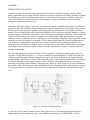
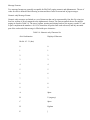
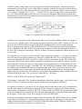
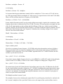
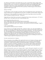
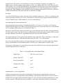
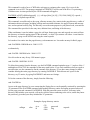
How does the paging system work as a whole? Let's investigate by looking at a typical paging system for
Any town, USA as shown in Figure 1-1. A page is initiated at a touch-tone phone. To page your spouse, for
example, you'd. dial a phone number assigned to the pager, wait for the automated voice prompt from the
paging terminal - "please enter a number followed by the # sign," enter the phone number where you'd like to
be reached, and hang up. The paging terminal, in turn, "makes up" the paging message for your spouse,
including your message and the address of the pager (ID), adds it to a stack of pages to be sent, and transfers
these pages within a few minutes to a bank of transmitters. Once transmitted, at the radio frequency assigned
to your paging service, your spouse's pager beeps after recognizing its unique ID - and stores the message
sent.
Figure 1-1: Commercial Paging System
As you can see, the system is similar to many other systems we use. In collecting paging messages, the
paging terminal simply prompts the caller - as a telephone answering device (TAD) would - to leave a
message. Your touch-tone phone and the telephone company's equipment does the rest. The paging terminal
has other jobs too. It must keep track of pairs of phone numbers and pager IDs, keep a record of messages
sent, control the transmitters spread out across the city, and manage the paging system as a whole. With intercity paging, so-called wide area paging, paging network controllers handle the job of exchanging pages
between cities and systems, often using the Telecator Network Paging Protocol (TNPP) to accomplish their
task.
The job of the transmitters is basic. They transmit a batch of pages upon demand, and may transmit each
page on all transmitters at once, called simulcasting. The messages are sent at the radio frequency (RF)
assigned to the paging service by the FCC using frequency modulation (FM). For numeric and alphanumeric
pagers, the digital information is sent with a frequency-shift-keying (FSK) modulation format. To send ones
and zeroes, the frequency of the transmitter signal, the carrier, is shifted (deviated) up or down in frequency
by 4.5 kHz.
The pagers complete the system. They wake up about once per second to look for a paging signal addressed
specifically for them. If a pager sees its ID in any of the pages being transmitted, it picks out that page, beeps
(or vibrates) the person carrying or wearing it, and stores the message (if a numeric or alphanumeric pager).
The person carrying the pagers is then free to display the message on the LCD.
First generation pager systems (beep-only and/or voice) were assigned to the VHF bands, 33-50 MHz and
139-175 MHz. Today, paging services are assigned VHF, UHF, and 900 MHz carrier frequencies as shown
in Table 1-1.
Table 1-1: Paging Frequency Bands
paging band
frequency range
VHF low band
33-50 MHz
VHF high band
138-175 MHz
UHF
406-422 MHz
UHF high
435-512 MHz
'900' band
929-932 MHz
In 1978, to accommodate more pages sent per hour per frequency and to include numeric or alphanumeric
messages in a pager signal, a standards group formulated a new paging format referred to at that time as
POCSAG. This pioneering planning was carried out by the Post Office Code Standardization Advisory
Group (POCSAG). A bit later the International Radio Consultative Committee (CCIR), a committee of the
International Telecommunications Union (ITU), renamed the POCSAG code as Radiopaging Code No. 1
(RPC1) and specified its format in their Recommendation for International Paging, R-584-1. We'll continue,
in this handbook, to refer to the RPCl as POCSAG. This protocol for sending paging messages is today's
defacto standard and its details are presented in Chapter 2.
You'll hear talk about Golay Sequential Code (GSC), Flex, and the Advanced Paging Operator Code (APOC)
paging formats. GSC systems (and pagers) are still in use in the US today, particularly in hospitals, but their
numbers are now small compared to POCSAG systems. Motorola has introduced and is pushing their new 4level FSK system, Flex, designed for higher speeds. (Flex is a trademark or registered trademark of
Motorola.) The APOC specification was written at Phillips Telecom and they are promoting it. None of
these paging formats will be covered in this handbook.
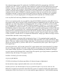
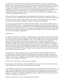
Figure 1-2: Amateur Paging System 2-meters or 70-cm.
You might wonder at this point how this all fits with amateur radio. Can we retrofit commercial pagers for
amateur use and can we encode, transmit and monitor pages? As it turns out, we're in luck on all four points!
First, some commercial POCSAG pagers made for the VHF and UHF frequency bands can be recrystalled
for the US 2-meter and 70-cm amateur bands. We'll investigate the insides of these pagers, buying them, and
converting them in Chapters 4, 5, and 6. Second, Kantronics' KPC-96l2 packet modem (v7.0) now includes
POCSAG encoding/decoding. A page message is encoded simply by typing in the pager ID and message
from a computer keyboard; the TNC does the rest - forming up the page and sending it to the transmitter.
We'll describe this process in Chapters 3, 7, and 8. Third, some of the 9600 "data ready" transceivers made
for packet radio operation are capable of transmitting and receiving POCSAG pages. We'll check this out in
Chapter 7. With these lessons in hand, you'll be ready to examine, convert, and apply pagers and paging
technology to our hobby.
Before reading these chapters, however, let's take a look at the POCSAG paging code as defined in
Recommendation 584-1 as described in Chapter 2. While this task will be a bit tedious, it's necessary. The
code is the foundation for everything else we'll do.
CHAPTER 2
THE DEFACTO STANDARD: POCSAG
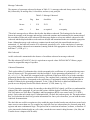
Introduction
The single purpose of this chapter is to describe the Post Office Code Standardization Advisory Group
(POCSAG) code used for sending and receiving numeric and alphanumeric pages. You might think of the
code as an alphabet, like the Baudot code for RTTY or the ASCII code for your computer serial port. The
term code as used here, however, is meant to be synonymous with the term protocol. The POCSAG code is a
description not only of the specific binary codes used but also of the format, rate, and signalling method used
in sending and receiving page messages.
The transmission format of the code is a preamble of 576 bits - alternating ones and zeroes - followed by one
or more batches of codewords. Each batch consists of a 32 bit synchronization codeword (SC) followed by
eight frames of 64 bits each, each frame consisting of two codewords. Codewords are defined as
synchronous, idle, address, and data. The format of the data codeword differs slightly from the rest, but all
codewords contain ten check bits for error detection and correction. The signalling (modulation) method
called for is frequency shift keying (FSK) with a deviation of 4.5 kHz.
The transmission rate for POCSAG is either 512, 1200, or 2400 baud. The rate and format of the code
determine the shortest duration possible for a page transmission (Table 2-1.) It's easy to differentiate between
rates when monitoring; simply listen for the pitch and duration of the preamble.
Table 2-1: Minimum Transmission Duration
baud rate
preamble (seconds)
batch (seconds)
total duration
512
1.125
1.0625
2.1875
1200
0.480
0.453
0.933
2400
0.240
0.227
0.467
Numerous descriptions of the POCSAG code can be found in the literature. I've found fairly complete
descriptions, with timing diagrams, in several pager theory/maintenance manuals. The most complete
description I've found from a protocol point of view, however, is "CCIR Recommendation 584," found in
part 2 of The Book of the CCIR Radiopaging Code NO.1. It's purpose is to define the codes, the error
detection/correction scheme, and the transmission sequence of the codes - the protocol if you will. I've
enclosed a summary of the recommendation in the next section. With the CCIR's description and some
experimentation, we were able to complete and port software into a packet modem to encode and decode
pages at 512, 1200, and 2400 baud, for both numeric and alphanumeric paging.
You may wish to obtain a complete copy of The Book of the CCIR Radiopaging Code NO.1. Five parts are
included: Part 1 - Introduction and System Definition, Part 2 - CCIR Recommendation 584, Part 3 Experience with the Code, Part 4 - Report of the Studies of British Post Office Standardization Code
Advisory Group (POCSAG), and Part 5 - Report of the Studies of the POCSAG. If so, I suggest that you
write the Radio Design Group, 3810 Almar Road, Grants Pass, OR 97527-4550. Ask for the "CCIR-l" book.
The last time I checked their fee for the book was $100 plus shipping. If you plan to write software/firmware
for encoding/decoding paging signals, I highly recommend that you obtain a copy. I make no guarantees that
the summary enclosed here is complete enough, without error, or suitable for any particular purpose. Clearly,
you are responsible for any code you write.
POCSAG CODE or Radiopaging Code No. J
A page transmission consists of a preamble and batches of codewords, each batch starting with a
synchronization codeword (SC). The format of the signal is tabulated in Table 2-1.
Table 2-1: Signal Format
preamble
batch
1
codewords
batch
2
codewords
batch 3...
10101010 ....
SC+16
codewords
SC+16
codewords
and so on...
Preamble
The preamble, used by the pagers to gain signal synchronization, is a pattern of alternating ones and zeroes,
repeated for a period of (at least) 576 bits.
Pagers may be designed to make use of the duration of the preamble to extend battery life. The receiver may
be left off most of the time but turned on often enough to catch a portion of the preamble. The rate at which
receiver power is cycled on/off depends, of course, upon the baud rate selected. Example. At 512 baud the
duration of the preamble is over one second; therefore, the pager could go to sleep for nearly a second at a
time without missing a preamble.
Batch Structure
Each batch consists of a SC and 16 additional codewords, a total of 544 bits. The sixteen codewords are
grouped in pairs, called frames. The frames are numbered 0 to 7 and the pager population is divided into
these 8 groups. Further, each pager is assigned to one of the 8 frames according to the 3 least significant bits
of its 21 bit identity, and only examines address codewords in that frame. Therefore each pager's address
codewords must be transmitted only in the assigned frame.
This frame structure within a batch not only multiplies the address possibilities of each codeword by 3 but
also offers an additional means of saving the battery within the pager, since the receiver need only be turned
on during the synch codeword and its particular frame. Thus the energy requirement is reduced by another
14/17ths prior to the message portion of the reception.
"Message codewords for any receiver may be transmitted in any frame but follow, directly, the associated
address codeword. A message may consist of a number of codewords transmitted consecutively and may use
one or more batches but the synchronization codeword must not be displaced by message codewords.
Message termination is indicated by the next address codeword or idle codeword. There is at least one
address or idle codeword between the end of one message and the address codeword belonging to the next
message. In any batch wherever there is no meaningful codeword to be transmitted, an idle codeword is
transmitted." (CCIR, The Book of the CCIR: Radio Paging Code NO.1, 1982, "CCIR Recommendation 584,
" Annex 1 p 9).
Types of Codewords
There are four codeword types: synchronization, idle, address, and message. All contain 32 bits which are
transmitted with the most significant (MSB) bit first. The SC is $7CD215D8 (hex), and the idle codeword is
$7A89C197 (hex). The SC and idle codewords are listed fully in Tables 2-2 and 2-3.
Table 2-2: Synchronization Codeword, $7CD215D8
position no.
BIT
position no.
BIT
1 (MSB)
0
17
0
2
1
18
0
3
1
19
0
4
1
20
1
5
1
21
0
6
1
22
1
7
0
23
0
8
0
24
1
9
1
25
1
10
1
26
1
11
0
27
0
12
1
28
1
13
0
29
1
14
0
30
0
15
1
31
0
16
0
32 (LSB)
0
Table 2-3: Idle Codeword, $7A89C197
position no.
BIT
position no.
BIT
1 (MSB)
0
17
1
2
1
18
1
3
1
19
0
4
1
20
0
5
1
21
0
6
0
22
0
7
1
23
0
8
0
24
1
9
1
25
1
10
0
26
0
11
0
27
0
12
0
28
1
13
1
29
0
14
0
30
1
15
0
31
1
16
1
32 (LSB)
1
Address Codewords
"The structure of an address codeword is illustrated in Table 2-4. Bit 1 (the flag bit) of an address codeword
is always a zero. This distinguishes it from a message codeword. Bits 2219 are address bits corresponding to
the 18 most significant bits of a 21 bit identity assigned to the pager ... Bits 20 and 21 are the two function
bits which are used to select the required address from the four ass1ned to the pager. Hence the total number
of addresses is 22 (over 8 million). Bits 22 to 31 are the parity check bits and the final bit is chosen to give
even parity." (CCIR, p. 11.)
Generally just one address is assigned to each pager and each is assigned one of the 8 frames for addressing;
hence the number of distinct pagers can be 218 +23 or 221 (over 2 million).
Table 2-4: Address Codeword
use
flag address
function
check bits
parity
bit nos.
1
2-19
20-21
22-31
32
value
0
as assigned
as assigned
as required
even parity
Message Codewords
The structure of a message codeword is shown in Table 2-5. A message codeword always starts with a 1 (flag
bit), followed by 20 message bits, 10 check bits, and one (even) parity bit.
Table 2-5: Message Codeword
use
flag
data
check bits
parity
bit nos.
1
2-21
22-31
32
value
1
data
as required
even parity
"The whole message always follows directly after the address codeword. The framing rules for the code
format do not apply to the message and message codewords continue until terminated by the transmission of
the next address codeword or idle codeword. Each message displaces at least one address codeword or idle
codeword and the displaced address codewords are delayed and transmitted in the next available appropriate
frame. Although message code words may continue into the next batch, the normal batch structure is
maintained, i. e. the batch will consist of 16 codewords, preceded by a Sc. At the conclusion of a message,
any waiting address codewords are transmitted, starting with the first appropriate to the first free· frame or
half frame." (CCIR, p 11.)
Idle Codeword
An idle codeword is transmitted in the absence of an address codeword or message codeword.
The idle codeword ($7A89C197 (hex)) is equivalent to capcode values 2007664-2007671 Hence, pagers
cannot be assigned this range of capcodes.
Codeword Generation
"Each codeword has 21 information bits, which correspond to the coefficients of a polynomial having terms
from x30 down to xl0. This polynomial is divided, modulo-2, by the generating polynomial xl0 + x9 + x8 +
x6 + x5 + x3 + 1. The check bits correspond to the coefficients of the terms from x9 to x0 in the remainder
polynomial found at the completion of this division. The complete block, consisting of the information bits
followed by the check bits, corresponds to the coefficients of a polynomial which is integrally divisible in
modulo-2 fashion by the generating polynomial. To the 31 bits of the block is added one additional bit to
provide an even bit parity check of the whole codeword. "(CCIR, Annex 1 p. 11.)
If you're planning to write software for encoding or decoding POCSAG signals, you'll have to understand the
content of the above paragraph. If you're not but curious what the algebra is all about, here's the scoop.
POCSAG makes use of the Bose, Chaudhuri, and Hocquenghem (BCH) error control code (31:21 BCH +
parity). Each codeword is made up of21 information bits, 10 check bits, and one parity bit. The math outlines
how you'd calculate the check bits given the information bits. Once you've done that, you can build the entire
codeword for transmission.
The check bits are useful in reception too; they enable the pager decoder board to not only detect errors but in
some cases to correct them too. For example, any single bit error in a codeword may be corrected using shift
registers and some combinatorial logic. This process can be carried out in hardware, software, or firmware. If
you're interested in further details on cyclic codes, consult the error control coding literature. (Lin, Shu, and
Costello devote a chapter to BCH codes).
Message Formats
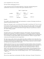
Two message formats are generally acceptable for POCSAG paging, numeric and alphanumeric. The set of
codes for each is defined in the following sections and these codes are not mixed in page messages.
Numeric-only Message Format
Numeric-only messages are limited to a set of characters that can be represented by four bits. By using just
four bits, airrtime is saved compared to the alphanumeric format. The sixteen symbols chosen for numeric
paging are listed in Table 2-6. The space, hyphen, opening and closing brackets, the urgency symbol 'U,' and
a spare compliment the numbers o to 9. Five characters are packed into each codeword, and any unwanted
part of the codeword of the message is filled with space characters.
Table 2-6: Numeric-only Character Set
4-bit Combination
Displayed Character
Bit No. 4 3 2 1 (hex)
0
0
1
1
2
2
3
3
4
4
5
5
6
6
7
7
8
8
9
9
A
Spare
B
U (urgency)
C
Space
D
Hyphen
E
]
F
[
Alphanumeric or general data format
Alphanumeric messages are limited to the set of characters included in The CCITT Alphabet No 5 (7 bits per
character). The bits of each character are transmitted in numerical order starting with bit No 1, and the
characters are transmitted in the same order as they are to be read. The pager address which introduces a
message (or segment of a message) using this format has its function bits set to 11 (decimal 3). (Some paging
services don't follow this format.)
"The complete message is partitioned into contiguous 20 bit blocks for the purpose of filling consecutive
message code words. Thus a character may be split between one message codeword and the next. Any
unwanted part of the last codeword of the message is filled with appropriate nonnprinting characters such as
'end of message,' 'end of text, null, etc. All characters, except null, are complete. " (CCIR, p. 12.)
That completes the brief but detailed description of the POCSAG code. In the next chapter, I describe how
one might apply it to a two-way communication system rather than for one-way paging. While this might
seem a bit strange, examining paging as a two-way digital system illustrates its similarity to RTTY, AMTOR,
Pactor, and G-TOR systems.
CHAPTER3
A TWO-WAY POCSAG OSO
It's true; we think of paging as a one-way transmission mode. However, the paging code (protocol) can just
as well be used in a two-way system, say between two amateur stations. You see, I'm thinking it may be best
to present paging systems for amateur use in this context. If you're a radio teletype (RTTY), AMTOR,
Pactor, G-TOR or packet operator, you can draw on your experiences with these modes to understand paging
systems. You'll see that paging equipment requirements and operations are similar, in particular when
compared to systems for 9600 baud packet. If you're not familiar with the digital modes listed above, give the
digital systems review; of comparison of these systems with paging systems; and the description of a twoway POCSAG QSO a try anyway.
digital systems review
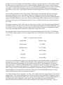
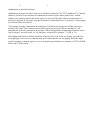
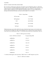
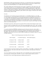
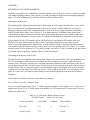
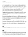
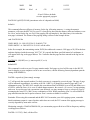
The system shown in Figure 3-1 consists of an antenna, a transceiver, a digital controller, and a computer. It's
a general digital system for the transmission and reception of data over radio. If the transceiver is a full
featured HF rig and the controller is an all-mode terminal node controller (TNC), then the system pictured is
capable of sending and receiving all of the popular HF modes listed above. If the transceiver is a general 2meter or 70-cm FM rig and the controller is a packet TNC, the system is capable of sending and receiving
packet radio frames. In either case, the job of the transceiver is to convert audio to RF or RF to audio, and the
job of the controller is to convert characters to sets of tones or sets of tones to characters. The computer
simply ships out characters to the controller or receives characters from it, using any generic communication
terminal program.
Figure 3-1: Monitor Station or Two-Way POCSAG Station
Let's take radio teletype (RTTY) as an example. For transmission, ASCII characters are sent from the
computer to the controller. The controller converts these 7-bit characters to 5-bit Baudot characters, and
transforms the bits into a sequence of tones. The tones are converted by the transceiver to a frequency shift
keyed (FSK) RF format for transmission. For reception, the FSK RF signal is converted to a set of audio
tones by the transceiver, converted to ASCII by the controller, and then displayed on the computer monitor.
For AMTOR, Pactor, G-TOR, and packet the job of the transceiver and the computer remains the same.
However, the controller gets extra work; it must control the sequence of events between stations, and it must
form and process groups of data, called frames. AMTOR frames consist of three 7-bit characters; Pactor and
G- TOR frames contain on the order of one hundred bits or more; and Packet frames contain several
thousand bits. For each of these modes complete frames are sent on each transmission instead of one
character at a time as with R TTY.
comparison
In all of these modes, except for 9600 baud packet, data presented to the transceiver or taken from the
transceiver is in the form of audio tones. Each bit of data is represented for a short duration by several cycles
of a specific audio frequency. For RTTY, a MARK (or 1) is represented by a 2125 hertz signal and a SPACE
(or 0) is represented by a 2295 hertz tone. For 9600 baud packet, each bit of data is transmitted at radio
frequencies (RF) by pulling the frequency above or below the carrier frequency by about 3 kHz and keeping
it there for the duration of the bit. This method is sometimes called direct FSK.
In a similar fashion, POCSAG paging uses the direct method of keying. As noted in chapter two, POCSAG
code is transmitted at 512, 1200, or 2400 baud. The direct method of keying requires a "data ready"
transceiver. For both 9600 baud packet and POCSAG transmissions, a bi-polar digital signal must be used to
drive the frequency determining element of the FM rig, usually the varactor. For 9600 baud packet and
POCSAG reception, discriminator audio must be used. Audio processing, in either case, distorts the signal
enough that it cannot be copied consistently.
There are differences between 9600 baud packet and POCSAG signalling in addition to baud rate. 9600
signals are scrambled during transmission while POCSAG signals are not. Scrambling keeps a signal
balanced; that is, the number of ones and zeros are kept in balance over a fixed number of bits. [With
POCSAG, it is possible to have a long string of ones or zeroes, and the result is a signal with low audio
frequency content. Hence, POCSAG transmitters must have a low audio response, around 20 to 50 hertz.
That means that data ready radios that have good low audio response as well as a wide audio response do
well with POCSAG. For this reason, some rigs advertised as 9600 "data ready" work for paging and some do
not.
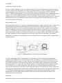
format of the paging signal
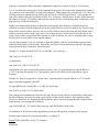
Before describing a set up for and the operation of a two-way POCSAG QSO, let's take one more look at the
format of the POCSAG signal (Figure 3-2). The reason for this is that we'll need to decide where to place the
address codeword for each transmission. The transmission format of the code is a preamble of 576 bits alternating ones and zeroes - followed by one or more batches of codewords. Each batch consists of a 32 bit
synchronization codeword (SC) followed by eight frames, each consisting of two 32 bit codewords.
Codewords are defined as synchronous, idle, address, and data. The format of the data codeword differs
slightly from the rest, but all codewords contain ten check bits for' error detection and correction (See
Chapter 2 for details).
Figure 3-2: Page Signal Format
According to the POCSAG code, each pager is assigned one slot in eight, i.e. one of the 8 frames in a batch
for an address codeword. Hence, in addition to the 18 bits assigned for addressing within an address
codeword itself, 3 more bits are (in effect) added to the address, establishing unique addressing for over 2
million (221) pagers on a given frequency. This assignment, of course, allows a pager to be turned off during
the time in which the non-assigned frames are received (without a message) which extends battery life. All
messages for a particular pager follow the address codeword for that pager.
the two-way POC5AG QSO
With this in mind, it makes sense, if we're going to have a QSO between stations - rather than a one-way
transmission to an actual pager, to use a pager address (capcode) located in the first frame of the first batch
transmitted. In this way, no pre-address frames are wasted. Such an assignment scheme is shown in Figure 33. We could use a capcode of 8, 16, 24, 32 ... 1234568, 1234576, and so on. By picking a capcode divisible
by 8, we'll insure that the address codeword is the first codeword transmitted following the prean'ible and
synchronization codeword. The remaining codewords and those that follow in additional batches can be filled
with data and (then) idle codewords.
Figure 3-3: Two-Way POCSAG QSO Transmission
Assuming you've operated one of the digital modes before, you've probably figured out how we're going to
set up a two-way POCSAG QSO. We'll arrange the station to operate just like a RTTY station. In RTTY, we
place the TNC in RTTY mode for reception and key the transmitter when we wish to send something.
There's nothing automatic about it, unlike AMTOR, Pactor, or G-TOR where the transmissionn-reception
cycle is controlled by the TNC. When we're ready to type a response, we'll key the transmitter (control-C T
for some TNCs) and type in the message. When we're done we'll enter a command to return the transceiver to
receive mode.
We can do the same for a two-way POCSAG QSO. Take another look at Figure 3-1. This station can be our
POCSAG station given that the transceiver is "data ready" and that the KPC-9612 (or an equivalent TNC)
can decode and encode POCSAG. Like RTTY we'll have to have a command to put the TNC in POCSAG
listen mode and we'll have to have another command to override that to send a page. So, while we describe
these commands in much more detail in a later chapter, let me introduce these two commands briefly so we
can complete our two-way example. For the KPC-9612, the PAGEMON command is used to monitor pages.
You simply type PAGEMON ON after the command prompt and the TNC is placed in receive mode. The
PAGE command is used to send a page and includes the following parameters: format, baud rate, pager
address (cap code), and message. For example, to send a page to an alphanumeric pager with ID 1234568 at
2400 baud with the message "Can you hear me Captain Morse?," We'd type:
PAGE -A-2400 1234568 Can you hear me Captain Morse?
The parameter -A directs the TNC to send an alphanumeric rather than a numeric page; -2400 calls for 2400
baud, 1234568 is an arbitrary first-frame capcode, and the rest is the message for Mr Morse.
Let's assume now that we've just placed our TNC in page monitor mode and received a CQ or transmission
from the other station. We will answer by typing the PAGE command, an arbitrary (first frame) capcode, a
short message, and hitting the return key. The TNC will then encode the full POCSAG message and transmit
it. Once the transmission is complete, the TNC returns to monitoring pages. When the distant station sends
his next page, we'll be ready to copy. We're having a two-way POCSAG QSO!
It's likely you can think of some improvements for this scheme right away, and I'll address ones I've thought
of now. Keep in mind that we've constructed this imaginary QSO only for the purposes of showing how
similar the transmission and reception of POCSAG is to the other digital modes. With that in mind, you're
probably as much an expert as I am now - maybe more so!
How about the improvements? I'd combine the P AGEMON and PAGE commands into a POCSAG
command. Like R TTY then, we could use control characters to switch back and forth between receive and
transmit. Of course, a capcode and the other page parameters would have to be assigned to the POCSAG
command - like MYCALL for packet. I'd also initiate a preamble immediately upon changing from receive to
transmit, and I'd not limit the number of characters to 128 per transmission. As it stands now, the PAGE
command is like the packet UNPROTO command; transmission does not start until the whole command,
including the message, is entered. Please keep in mind, however, that these commands were designed to
work that way; we're just imagining how we'd change the PAGE command into a full blown mode!
a two-way POCSAG OSO using TERMINAL in Windows and a KPC-9612 TNC
Still, we can experiment with a two-way QSO by using the PAGEMON command to put the KPC-9612 in
page monitor mode and by using the PAGE command to initiate an alphanumeric page at 2400 baud. For this
experiment, my station setup consists of a Kantronics KPC-9612 (version 7.0 firmware), a Kenwood TM251A data ready radio, a 486-66 PC, and the TERMINAL program in Windows 3.1. I've set up two function
keys in TERMINAL, as shown in Figure 3-4, to place the TNC in monitoring mode and to initiate pages.
PAGEMON is defined as function key 1 (Fl) and the PAGE command less the message is defined as function
key 5 (F5). When Fl is pressed, the TNC is placed in page monitor mode. When F5 is pressed, it overlays the
monitor function, and automatically types out all of the PAGE command except the message. For example,
when F5 is pressed, the cmd: prompt is called for (using the control-C directive) and the text string "PAGE A-2400 1234568" is entered for me. To complete the transmission, I simply type whatever message I wish to
send and follow that with a return (carriage return).
Using these techniques, a simulated QSO is displayed in Figure 3-5. It's simulated in that I supplied the
receive signal from my own transmit signal; I looped the output of the KPC-9612 (TXA) back into the input
(RXA). In this way, without a partner out there somewhere, I could experiment with having a two-way QSO!
(By the way, the loop back, if you have a KPC-9612 at 7.0 and want to try this, is pins 2 and 3 of port 2. I
used a paper clip!)
At the top of the screen, you'll see that I put the TNC is page monitor mode. I then clicked on F5 to initiate
the entry of the page command. After that, I simply typed my CQ message at the keyboard and followed it
with a return. Within a fraction of a second, the page was send and simultaneously monitored. Each page
received consists of the following fields : header, pager ID (capcode), type of page character, optional time
and date stamp, and message. For my page, I received
PAGER> 1234568(3) [03/16/96 14:00:00]:
CQ CQ CQ DE W0XI K
1234568 is the arbitrary first-frame page address (3) denotes the page as alphanumeric
the date and time stamp is optional (added at the receive side of the QSO)
So there you have it, the full description of a two-way POCSAG QSO. As you can see, there are few
differences in equipment requirements when POCSAG systems are compared with the other digital modes.
At this point, it's time for us to move on. Let's look inside the pagers themselves. You'll find them amazing.
CHAPTER 4
DIGITAL PAGERS: RECEIVER AND DECODER
The vast majority of digital pagers sold today are designed to receive Radiopaging Code No. 1 (POCSAG).
They receive numeric or numeric/alphanumeric messages at either 512, 1200, or 2400 baud, 1200 being most
common. Pagers are made for all of the popular business bands, as listed in Table 4-1. A typical pager
features a liquid crystal display (LCD), is housed in a high-impact plastic case, contains FM receiver and
microprocessor-based decoder boards, and is powered by a single AA or AAA battery.
Table 4-1: Pager Bands
VHF low band
33-50 MHz
VHF high band
138-175 MHz
UHF
406-422 MHz
UHF high
435-512 MHz
'900' band
929-932 MHz
Within brand, many pager models will utilize the same decoder board and a range receiver boards to span
each radio band. For example, the VHF version of the Bravo Plus, by Motorola, may be made with one of
seven radio receiver boards listed in Table 4-2. A UHF Bravo may be made with a board listed in Table 4-3.
Table 4-2: VHF Page Receiver Boards
Part No. VHF Receiver Board*
Frequency Range MHz
AARD4050A
138-143
AARD4051A
143.148.6
AARD4052A
148.6-152
AARD4053A
152-159
AARD4054A
159-164
AARD4055A
164-169
AARD4056A
169-174
* A similar sub-band applies to the earlier Bravo "NRD" boards. See MRT magazine, Sept 1994.
Table 4-3: UHF Receiver Boards
Part No. UHF Receiver Board
Frequency Range MHz
NRE6550B
406-423
NRE6551B
435-450
NRE6552B
450-465
NRE6553B
465-480
NRE6555B
495-512
Most paging receivers are dual-conversion superheterodynes with a quadrature detector tacked on for
demodulation of the (FM) paging signal. Most include a preamp, a first IF at either 17.9 MHz or 45.00 MHz,
a second IF at 455 kHz, a "peak and valley" detector, and a discriminator. The rest of the pager consists of
the decoder board with power supply
module, various switches and connectors - for programming ID (capcode) and format, and the LCD. The
decoder board contains a microprocessor, programmable ready-only memory (prom), electrical erasable readonly memory (EEPROM) (also called a code plug), random access memory (RAM), and power control
circuitry. Let's take a closer look at a typical receiver board.
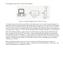
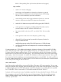
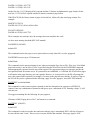
Typical Pager Receiver Board
While synthesized receiver boards are beginning to appear, nearly all receiver boards in use are crystal
controlled superhetes, as shown in Figure 4-1. The antenna and preamplifier receives, filters, and amplifies
the paging signal. The oscillator, multiplier, and mixer converts the paging signal to the first IF frequency. A
crystal filter adds selectivity, and the second oscillator and second mixer converts the paging signal to the
final IF, 455 kHz. A ceramic filter at 455 adds further filtering, and the discriminator converts the FM signal
to audio. You're right! It's just a single-channel dual-conversion FM receiver!
Figure 4-1: Pager Receiver
Napier (of math fame) once said that we don't know anything about something unless we can put numbers on
it. So, let's pick a paging carrier frequency (paging provider's transmit frequency) and apply it to our typical
receiver to see what happens! Let's try 152.840 MHz, a common commercial paging frequency. Most VHF
high band pagers utilize a 17.9 MHz first IF. Hence, with the IF set, the oscillator and multiplier must supply
a signal to the mixer with a frequency that is 17.9 MHz less (or more) than the received carrier, or
.
foscillator multiplier = fcarrier - IF
or rearranging,
foscillator = (fcarrier - IF) / multiplier
Let's assume that the pager maintenance manual calls for a multiplier of 3 for a carrier of 152.840. (In fact,
my VHF pager manual calls for a multiplier of 3 if the receive is to operate between 148.6 and 174.00 MHz).
Hence, our first oscillator must have a frequency of 44.9800 MHz.
foscillator = (152.840 -17.9)/3 = 44.9800 MHz
In turn, with the first and second IF set, the second oscillator must supply a signal to the second mixer with a
frequency that is above or below the first IF by 455 kHz. The mixer, of course, produces two signals: the sum
of the first IF signal and the second oscillator and their difference. Either way, with the second oscillator
frequency offset by 455 kHz from the first IF frequency, a 455 kHz second mixer signal is produced. The 455
kHz ceramic filter eliminates that "sum" frequency. In numbers then, assuming our pager service manual
calls for a low-side second oscillator:
ffirstIF - f2nd oscillator = 455 kHz
or rearranging,
f2nd oscillator = f first IF - 455 kHz
f2ndoscillator = 17.9 Mhz - 0.455 Mhz = 17.445 Mhz
Napier would be proud!
Now let's try an amateur 2-meter frequency, 145.07 MHz, and see how the numbers work out. My Bravo
Plus service manual calls for a times-two multiplier and low-side injection when using an AARD4050 or
AARD4051 receiver board (for 138 to 148.599 MHz). Again the first IF is 17.9 MHz. Therefore, the first
oscillator crystal must be made for
fosc = (145.07 -17.9 )/2 = 63.585 Mhz
If we wish to convert a higher frequency board, e.g. an AARD4052 or AARD 4053 (made for the sub-bands
148.66152 and 152-159 MHz), we'll have to use a times 3 multiplier or change parts. Using the 4053,
fosc = (145.07 -17.9)/3 = 42.390 Mhz
The manual states (for the 4051 board) that the 2nd oscillator must be low-side, 455 kHz below the first IF.
So, my second oscillator must have a frequency of 17.445 MHz. In addition, the manual states that the range
of the first LO can be about 43 to 65 MHz, so the pager will work for 145.07! (In fact it does!) As you can
see, there is not substitute for obtaining and using the maintenance and service manuals for your pager in
order to recrystal for the amateur bands.
The Multiplier and the Overtone Crystal
The multiplier factor used in calculating the required first LO crystal frequency should not be confused with
the "overtone" multiplier of the crystal itself. In the receiver, the output of the crystal oscillator circuit is
MULTIPLIED to obtain the signal needed at the first mixer. As mentioned in the previous paragraph, the
4052 receiver board is capable of supporting an LO operating frequency of from 43 to 65 MHz. It is this
frequency that is MULTIPLIED by 2 or 3 to obtain the mixer injection frequency.
The crystal oscillator itself, at least for the Bravo-series pagers, is operated as a 3rd overtone circuit. The
crystal used is (usually) an 'AT' cut which supports overtone oscillations, when placed in the appropriate
circuit, of three times the fundamental of the crystal itself. So, the fundamental frequency of the crystal is
actually 43/3 MHz at the low end and 65/3 MHz at the high end for the 4052 receiver board. Third overtone
circuits are used simply because fundamental crystals cannot be made as high as 43 MHz but reach a limit of
manufacturability at about 25 MHz.
Inversion
Given that the receiver board of your pager is built for the 142 - 148.6 MHz sub-band, you can readily
recrystal it. However, some portions of the 2-meter band require that the 2nd oscillator be above the 2nd IF
(i.e., 18.355 MHz) while other portions require that the 2nd oscillator be 455 kHz below the 2nd IF (i.e.,
17.445 MHz). So, you might have to change the 2nd LO crystal too. (See Table 4-4). So what? Why bother
with high-side 2nd LO injection in the first place if it causes these hassles? "Well," as Reagan said, if you
don't, you'll find that some 2nd LOs (either high or low injection) have harmonics that fall right in the middle
of the receiver front-end pass band!
When high side injection is called for, the received data will be inverted at the discriminator output. It's just
the same as with lower sideband (LSB) versus USB when operating digital modes on HF ; when you change
sidebands, you invert the data. All is not lost; however, the decoder board can be programmed to reinvert the
data.
You see, the decoder board EEPROM (codeplug) keeps track of inversion. Inversion, when needed, is
generally programmed at the same time the capcode is changed. Each manufacturer sells a programmer for
their pagers - they run around $300 or so, but you might want to pick a frequency that doesn't require
changing the status of your inversion bit in the EEPROM (codeplug), thus avoiding the expense of or time in
locating a programmer.
Table 4-4: 2nd LO Requirements for the Bravo Plus for 2-meters
carrier frequency
1st oscillator frequency
2nd oscillator frequency
143.6660-143.7060
62.8830-62.9030
18.355
145.5060-145.6990
63.8030-63.8995
18.355
145.9610-146.0020
64.0305-64.0510
18.355
146.1130-146.1460
64.1065-64.1230
18.355
*2-meter frequencies not listed in the table would use a 2nd oscillator of 17.445 MHz. A similar table would
apply to other pagers. (The entries in this table were taken from my Bravo Plus Maintenance Manual, by
Motorola, Inc.)
Are you out of luck if you pick up a used pager with a receiver board that does not span the amateur band
you're interested in? Not necessarily. The 4051A, of course, is ideal for amateur radio use for the 2meter'band. It's just a crystal change and tuneup, resulting in good sensitivity.
In most cases it's possible to convert other boards, such as the 4052A board - which is just above the 2-meter
band ˆfor VHF use. In order to meet sensitivity specifications (and perhaps to keep spurs down too) you may
have to change out a few surface mount parts and/or the oscillator coil. The results of such an experiment are
presented in Chapter 6.
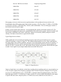
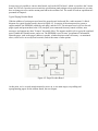
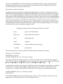
Typical Paging Decoder Board
With the addition of a microprocessor board, the pager doesn't look much like a radio anymore! A block
diagram of a typical decoder board is shown in Figure 4-2. It consists of the microprocessor system, a
support module, the EEPROM (called the code plug), and the LCD. The microprocessor's job is to decode
pager signals and present them to the LCD, interpret your commands from any control switches, store
messages, and support any other "features" the model offers. The support module's job is to provide regulated
power, handle the vibration motor, and so on. The EEPROM is used to store "programmed" information
about the pager, such as the pager's address (capcode), whether data inversion is necessary - as mentioned
above, select twelve or twenty-four hour time, and set the status of other options.
Figure 4-2: Pager Decoder Board
At this point, we've covered enough material to move on· to our main target, recrystalling and
reprogramming pagers for the amateur bands, the next chapter.
CHAPTER 5
BUYING A PAGER FOR AMATEUR RADIO USE
You have three choices in selecting a pager for 2-meter or 70-cm amateur use: buy one already cry stalled for
one of these bands, buy a new or refurbished commercial band pager and recrystal it, or pick up a used pager
and convert it. Recrystalling procedures are covered in the next chapter. If you find a commercial pager for
sale, make sure it's convertible for 144-148 or 435-450 MHz use before purchasing it. If you buy a used
pager, you have three questions to answer: does it have the features you need, does it work, and is it
convertable. Let's address these choices one at a time.
Amateur Pagers
Kantronics offers refurbished Motorola Bravo-series (Bravo Plus, Bravo Classic, Lifestyle Plus) numeric
pagers recrystalled for the 2-meter and 70-cm bands for the frequencies listed in Table 5-1. They also
maintain a crystal bank of these popular frequencies for the do-it-yourselfer. (Remember to check first with
other amateurs in your area before settling on a frequency for pager use. They'll thank yoy if that frequency is
already in use or planned for!)
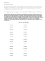
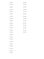
Table 5-1: Popular 2-meter/70cm Pager Frequencies (MHz)
145.070
145.090
145.630
144.730
145.770
149.895 (CAP)
441.000
441.075
446.150
145.670
CAP is the Civil Air Patrol
Commercial Pagers
Buying and converting a commercial pager is a viable option. First of all, you're pretty sure the pager is
working. You simply need to select the right pager and then convert it or have it converted. Sources for these
pagers are discount stores, specialty stores catering to cellular phone and pager users, the paging providers
(services) themselves, and sometimes two-way radio shops. Check the yellow pages for your area. Most of
these outlets will sell you a pager outright; some will refuse to do so if you don't sign up for their commercial
service, typically $10 to $15 per month!
How should you select the pager?
My experience is with the Bravo series mentioned above. I've converted these pagers originally manufactured
for 148.6-152 and 152-159 MHz for 2-meter use and made for 435-450 and 450-465 MHz for 70-cm use. If
you find a shop that has Bravo series pagers cry stalled for operation within these frequency bands, they
should be suitable for recrystalling for amateur use. Some shops carry '900' MHz pagers only, since they're a
reseller for a 900 service. The receive board in these pages isn't convertable for amateur use; however, the
decoder board might be useful as a spare. If the price is right, consider buying the unit for that reason. If your
club or group plans to operate a paging system on 2-meters, then select a pager with the receiving frequency
that falls between 143-148.6, 148.6-152 or 152-159 MHz.
If you can't find Bravo series pagers, you might consider Motorola's Express or alphanumeric series. Most of
these pagers made for the 150 and 450 bands use the same crystal-based receiver boards as the Bravo series.
So, chances are you'll be able to convert them. However, since I've not done that, take my suggest with a
grain of salt; that is, you are on your own! I recommend that you obtain a service manual for the pager you're
considering to buy or buy, or research it by scanning the many articles listed in the bibliography. David
Ludvigson's 16 article series on pagers appearing between late 1994 and early 1996 in Mobile Radio
Technology would be an excellent start. He too focuses primarily on Motorola pagers, but the material is
applicable to other pagers as well.
Buying a Used Pager
You third choice is to buy a used pager. If you know what you're looking for this can be a great option. The
pagers mentioned above are rugged and they last a long time. I wouldn't be concerned if they're simply old. If
you find some, it's likely that they'll be convertable. If you can buy a bag of them, you have an excellent
chance of getting one going from the parts - a fun project!
What should you look for? Make sure the unit is working first! Insert a battery into the pager, a 1.5V AA for
the Bravo-series - tip of battery goes in first - and perform these tests:
Does the pager beep when you turn it on?
Does it vibrate when you turn it on? (optional feature in some models)
Does the LCD readout work? (all the characters there?) Are the buttons working? (not stuck)
Does the label on the back list the receiver's frequency? Does the label on the back list the pager's 7 digit ID
(capcode)?
Is the case in good shape?
Are the printed circuit boards clean (not corroded)?
If you can answer yes to all of these questions, then - if the price is right - you've got a good candidate. For
the Bravo series, the pager should beep when you push the power switch on the side of the unit fully toward
the LCD. If you push it half-way, it should vibrate (if the pager has that feature - some don't). In either case,
the LCD should display the time of day and/or sequence through the LCD characters. If some of the
characters are missing or the LCD doesn't display anything, pitch that pager! For the Bravo series, try
pushing the menu and read buttons. The LCD should cycle through various messages, such as set time or
display time. If nothing happens, chances are the switch is bad or the plastic case holding the switch is worn.
Consider buying two pagers and using the parts to get one to work.
key items: capcode and receive frequency
Key to your purchase is the availability of the capcode and current receive frequency of the pager, printed
(usually) on the back panel labels. Without this information, you are not going to be able to determine
convertability. The labels should contain the following: phone number, serial number, FCC ID number,
frequency of reception, and capcode. If the pager's for sale, it's likely the phone number is discontinued;
anyway, it's of no use to you. If a pager has been in use for some time, some or all of the labels may be
missing. If they're still there, it's possible that the information is no longer current. If the capcode and
frequency are listed, I'd take the chance; I'd buy the pager.
If you can't determine the current receive frequency and/or capcode of the pager by inspection, you can still
find these facts out if you have access to the right test equipment. You'd need a quality frequency counter to
determine whether or not the LO is working and its frequency of operation. In addition, you'd need a "pager
programmer" for the particular model you're considering. A programmer consists of an RS-232 interface
between the pager and your PC and software. Pager programmers exist for each brand and model of pager.
They're used to read the current contents of the pager's code plug (eeprom) and to reprogram it. Most beeper
shops have a programmer for the units they sell and support but they usually don't have the RF test gear.
Two-way shops usually have the RF test equipment and sometimes have the pager programmers. That's life!
I recommend not purchasing a pager if the labels are missing and you don't have access to a shop(s) with the
necessary RF test equipment and pager programmer. There is one final option: if your club plans on
programming a lot of pagers, you might consider standardizing on one pager and purchasing the pager
programmer.
Assuming your pager looks good at this point, it's time to recrystal it and, perhaps, reprogram it for amateur
use. These are the subjects of the next chapter.
CHAPTER 6
RECRYSTALLING, REPROGRAMMING
Assuming your pager is new, refurbished, or used and appears to be working, it's time to recrystal it to match
your amateur paging frequency. Here you have two tasks, obtaining the right crystal and tuning/aligning the
pager. Let's look at finding the crystals first, likely the harder of the two tasks.
obtaining the right crystal
I'm assuming in the following discussion that you'll be using one of the pagers from the Bravo-series. If not,
there is no substitute for obtaining maintenance and service manuals, working with a two-way shop, or
finding an amateur friend to help in determining the crystal needs for your pager. Kantronics maintains a
bank of crystals for the Bravo series (Table 6-2). You might start there. In addition, most major crystal
vendors produce pager crystals for most of the major pager brands, and some may be willing to take retail
orders for amateur frequencies. However, don't be surprised to find high prices and multi-week lead times.
For my Bravo Plus, the VHF manual calls for a KXN6300AA crystal and the UHF manual calls for a
KXN6301AA; that's all the manual provides. Most crystal houses know how to make these crystals,
however, given the manufacturer's number; they've made millions of them. I, like most amateurs, however,
want to know about the technical aspects of the crystal too, not just purchase them. So I dug a bit. As it turns
out, most pager first La crystals are 'AT' cut, third overtone, are used in a "series" resonant circuit, have about
5 picofarads (pf) of capacitance, and have about 25 ohms of resistance.
calculating the frequency of the crystal
The hardest step in recrystalling is determining what frequency the first oscillator (LO) crystal should be cut
for. We can determine what's needed, even without the service manual in most cases, with a little bit of
detective work. The pager's current receive frequency should be printed on a label on the back of the unit. If
not, open the pager up and see if the frequency of the first LO crystal is printed on the side of the crystal can.
If both of these clues are missing, the person you purchased the pager from might be able to tell you which
commercial service the pager was used for in your area. That would determine the receive frequency of the
pager. As a last resort, you might consider finding a friend with the equipment to measure the oscillator's
frequency.
For the Bravo series the LO frequency must follow this formula:
fLO = (fcarrier - first IF) / multiplier factor
For receiver boards made for the 138 to 175 MHz range, the multiplier will be either a 2 or a 3. For receiver
boards made for the 435 to 512 MHz range, the multiplier is 8. LO frequencies for 2-meters and 70-cm are
listed in the tables below.
Table 6-1: LO Frequency Range for Bravo Series
VHF/UHF Pagers CAP is Civil Air Patrol
receive freq (MHz)
1st IF (MHz)
multiplier
LO freq (MHz)
143-148.9
17.9
2
62.55-65.35
149.895 (CAP)
17.9
3
43.9983
435-450
45.0
8
48.75-50.625
Table 6-2: Kantronics Pager Crystal Bank
(fax 913-842-2031, website http://www.kantronics.com/)
Carrier MHz
IF MHz
Multiplier
1st LO MHz
145.070
17.9
3*
42.3900
145.090
17.9
3*
42.3967
145.630
17.9
3 *#
42.5767
145.670
17.9
3 *#
42.5900
145.730
17.9
3*
42.6100
145.770
17.9
3*
42.6233
149.895
17.9
3*
43.9993
441.000
45.0
8
49.5000
441.075
45.0
8
49.5094
446.150
45.0
8
50.1438
* Assumes that a 4052 or a 4053 board (most common) is used to convert the pager to a 2-meter operation. #
Indicates that inversion is called for; hence a 18.355 kHz 2nd LO crystal is also required. If a 4051 board is
used for 2-meters, the multiplier should be 2 as in Table 6-1.
installing the crystal
Installing the LO crystal is straightforward. Remove the receiver board from the pager case; locate the first
LO crystal; remove it using a soldering iron and solder wick, clean the printed circuit pads, and insert and
solder the new crystal in place.
Again, I'm assuming that you're working with a Bravo Plus, Bravo Classic, or Lifestyle Plus pager.
Removing the back of the case exposes the bottom side of the receiver board (Figure 6-1). The antenna is at
the left, the first LO crystal is at the top, the LO tuning slug (coil) is just below the crystal, test point M1 is at
the upper right, and the 8-pin data header is at the bottom. Remove the board by grasping it near the 8-pin
header and opposite side with thumb and forefinger. You can also use a pencil as leverage; place one end
under the board and use the switch as a pivot point.
Figure 6-1: VHF Receiver Board AARD405X Series
tuning up the pager
Once you've placed the receiver board back in the pager, you're ready to tune it up. Here you have two
choices: have a friend send you pages while you tune the LO slug or find someone who has the proper test
equipment to do the job. (Maybe you're like all hams; you purchased a signal generator, counter, dual-trace
100 MHz scope, and pager radiation test fixture with your tax refund. Sure!)
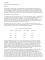
The preferred method of tuning is to use the test equipment shown in block diagram form in Figure 6-2.
You'll need a POCSAG signal encoder (the KPC-9612 with firmware version 7.0 will do), a 150- 450 MHz
RF signal generator, an AC voltmeter, and, a frequency counter covering 455 kHz. An oscilloscope with
counter can, of course, substitute for the AC meter and counter, and some techs prefer it. Follow the steps
outlined in Table 6-3 for tuning the pager to the new crystal frequency.
Figure 6-2: Pager Test Station
Table 6-3: Recrystalling Tune-Up Procedure (for Bravo-series pagers)
step procedure
1
install a 1.5 V batter in the pager
2
put the page in self-test mode (so it doesn't cycle-snooze - tp put the
pager in self-test, hold the menu and read buttons down while turning
the unit on, then immediately press the read button.)
3
attach the RF generator to the pager radiation test fixture (or attach an
antenna to the generator and place the pager near the antenna)
4
attach the AC voltmeter to test point M1 of the pager (the 455 kHz IF)
5
set the generator to a frequency matching the first IF, and increase the
generator output so the AC voltmeter reads half-scale
6
the counter should read close to 455, say within 1 kHz. Not its readout
value
7
set the generator to the exact carrier frequency you'll be using
8
adjust the LO coil (or cap) until you match the frequency obtained in
step 6 to within 200 hertz
9
modulate the generator with a 200 to 600 hertz tone at 4.5 kHz deviation
and adjust the other front end components for a maximum reading on the
AC voltmeter
You may question step 5. Why bother with noting the deviation in frequency of the second IF (455 kHz)
when driving the pager with a signal equal to the first IF frequency (17.9 MHz for 2-meters)? Here's why.
You have to use the counter reading at (near) 455 kHz to accurately set the first LO's frequency. It's likely
that the first IF crystal filter will be cut 'on frequency,' but it's also likely that the 2nd LO will not be exactly
on frequency - since it's not tuneable .. It could be off a kilohertz or so due to parts variations. Hence, you'll
have to tune the first LO such that it converts the incoming signal to exactly 45 MHz. To do this, you'll have
to use the counter reading of the 455 output (2nd IF)! If it was offset, to say 456 in step five, it must be tuned
to 456 when you are tuning the first LO for real!
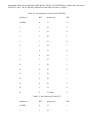
some actual examples
I used the procedure outlined above to recrystal five Bravo Plus pagers for 2-meter operation. My test setup
differed a bit in that I had a radiation fixture to hold the pagers, a scope with a built in frequency counter, and
a calibrated signal generator (IFR-1200A). Before conversion, the pagers were working and were crystalled
for 152.840 MHz. All were converted to 147.650 and the results are listed in Table 6-4.
I replaced the LO crystal (used a times 3 multiplier), tuned the LO slug so that the IF showed 455 kHz, and
then sent pages to each unit 10 check that they were receiving messages. I then decreased the generator
output, each time sending a page, until the pager did not respond. All of the pagers exceeded their 4 u V
sensitivity specification.
Table 6-4: Five Pagers Recrystalled for 2-meters (from 152.840 to 147.650 MHz)
unit baud rate
receiver board
generator
RTF pad*
sensitivity
1
512
AARD4053D
-66 dBm
-40 dB
-106
2
1200
AARD4053A
-62
-40
-102
3
1200
AARD4053A
-64
-40
-104
4
1200
AARD4053D
-66
-40
-102
5
2400
AARD4053D
-62
-40
-102
The 4053 is not the ideal board for 2-meters. The 4051 would be ideal, since it was made for the band
segments including 144-148 MHz. However, as you can see, we met the spec anyway. As expected, the 512
baud pager had the best sensitivity.
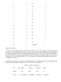
I also used the test setup noted above to convert a number of UHF pagers, from 452.000 to 445.300 MHz.
The results are listed in Figure 6-5. This time I listed the before and after sensitivities. As expected, they
were about the same. I found one unit that had a low sensitivity before conversion, but once converted and
tuned it was fine. I can only assume that it was not peaked originally.
Table 6-5: Pagers Recrystalled for 70-cm Operation (from 452.00 to 455.300 MHz)
unit baud rate
receiver board
sensitivity before
sensitivity after
1
512
NRE6552C
-92 dBm
-92 dBm
2
1200
NRE6552C
-70
-88
3
1200
NRE6552A
-88
-88
4
1200
NRE6552B
-90
-90
5
1200
NRE6552B
-90
-90
6
1200
NRE6552A
-88
-88
7
2400
NRE6552B
-88
-88
note: sensitivity reading does not include the -40 dB attenuation of the RTF.
CHAPTER 7
SETTING UP A PAGING SYSTEM
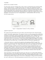
Now that you have the basics of paging under you belt, it's time to assemble and operate an amateur paging
system. As shown in Figure 7-1, a paging system consists of a computer and communication terminal
program, a POCSAG encoder/decoder, a data ready transceiver, an antenna, and pagers (not shown). We'll
reexamine the requirements for each of these pjeces of equipment, describe how to interconnect the encoder/
decoder and data radio, discuss transmitter drive levels and receiver equalization needs, introduce a set of
paging commands for the encoder/decoder, and demonstrate how to send a page or monitor a page. For these
descriptions, we'll assume the use of a PC running Windows 3.1 and the Kantronics KPC-9612 as the
POCSAG encoder/decoder.
Figure 7-1: Paging Station: Transmit, Two-Way, or Monitor
equipment requirements
The computer and encoder/decoder (TNC) in an amateur system take the place of the commercial paging
controller, often called a paging terminal. The computer is used to set up the parameters of the encoder and to
enter pages for transmission. Any basic communication terminal program, such as TERMINAL in Windows,
can be used to carry out these jobs. Encoding/decoding can be carried out in a PC or in a TNC. The
asynchronous format of the PC RS-232 serial port makes PC implementation problematic. The KPC-9612 is
a good encoder choice for several reasons: it's easily located remotely, paging can be supported via a packet
radio connect at port 1, pages can be sent via a telephone modem I attached to the RS-232 port, and the 9600
baud integrated circuit modem in port 2 accommodates the POCSAG synchronous signalling format.
A "data ready" transceiver is required for the transmission and monitoring of POCSAG signals. This
requirement is a must for two reasons: the modulation format for POCSAG is FSK at 4.5 kHz and the audio
frequency content of the signal is low. Neither requirement can be met by typical offfthe shelf voice-based
VHF and UHF FM rigs. In addition, not all of the so-called data ready rigs can handle POCSAG's severe
requirements. Signal frequency content as low as 50 hertz must be supported for both transmission and
monitoring. Direct (varactor or varacap) drive must be used for transmission, and discriminator audio must
be available for monitoring. Speaker audio will not work. As you can see, if it weren't for the development of
a 9600 baud packet modem integrated circuit chip (IC) and subsequent availability of data ready radios,
amateur paging might not be with us today.
Why is the frequency content of the POCSAG signal so low? The source is two-fold: the FSK modulation
format and the absence of any bit stuffing or data scrambling in forming up a pager signal. (This is in contrast
with the formation and transmission of 9600 baud packets where both bit stuffing and scrambling are used,
eliminating the possibility of long strings of ones or zeroes). With paging, if a string of one bits is called for,
the carrier is shifted up by 4.5 kHz and maintained there until all the ones are sent. For zeroes, of course, the
opposite is true. The carrier is never returned to its center or "operating" frequency. For example, if a
numeric page is sent that contains a large number of zeroes, say a phone number 842-1000, fifteen zero bits
will be sent in a row ( or 1000 0000 0000 0000). The transmitter (and the pager) must be able to handle these
one-sided signals. Pagers and commercial paging transmitters are, of course, designed to do so. Given the
low data rates, FSK modulation, wide deviation, and non-scrambling signal format of POCSAG, 1200 baud
(AFSK) and 9600 baud 'RUH' packet modems are unsuitable for paging.
the pagers
Any of the POCSAG pagers used or sold today may be suitable for amateur use. The key is to find those that
can be converted for 2-meter or 70-cm use. I describe how to find and convert pagers in the Motorola Bravo
series in Chapters 5 and 6. Other brands are, of course, convertable too.
interconnecting the encoder and transceiver
Page transmissions and monitoring are handled by the KPC-9612 via port 2. If you have a 9612 and are
running 9600 baud packet, you might as well skip this section; you're ready to go! Otherwise, you'd cable the
9612 to a paging capable transceiver as tabulated in Table 7-1.
The push-to-talk (PTT) line connects to the PTT pin on your radio and causes the radio to transmit when the
TNC has a page to send. Your radio may have a different name for this pin, perhaps standby (STBY); use the
pin whose function is described as "grounding this pin will cause the radio to transmit."
The transmit data pin (TXA) connects to the modulator stage of the radio. Those radios that are "9600 ready"
may identify this pin as the "9600 baud data input (from your TNC)" or as "data transmit."
The receive data line (RXA) connects to the data output pin of your radio. Your radio manual may identify
this pin a discriminator out, discriminator audio, or as data receive. Don't connect to speaker audio.
Don't forget to add ground. It's a good idea to connect the cable shield too but just at one end; signal ground
and shield ground can be the same there.
Table 7-1: Encoder/Decoder to Data Radio Wiring
Signal Name
KPC-9612, port 2, pin #s
Push-to- Talk (PTT)
pin 1
Receive Data (RXA)
pin 2
Transmit Data (TXA)
pin 3
Ground
pin 11
transmitter drive, receiver equalization
All data ready transceivers are not alike! Profound huh? For that reason, transmitter drive and receiver
equalization will have to be adjusted for each installation. The following outlines how to set these levels for
the KPC-9612 and a typical data ready radio. Jumpers J7, J8, and J9 and associated potentiometers are used
for these purposes. With most data ready transmitters, a mid-range adjustment of the drive potentiometer
(pot) and J7 set on both pins produces sufficient deviation for POCSAG activity. It's a good idea to use a
deviation meter to check your setting. I've found that most pagers won't respond to a page if the deviation is
set below 3 kHz, and the POCSAG standard calls for 4.5 kHz. F or reception, most data ready receivers copy
most pages with jumpers J8 and J9 set in their default positions. Some receivers require more or less
equalization, and in these cases, place jumper J8 on pins C and 2 and adjust the pot for best reception. If you
plan to monitor pages with a shop monitor , such as an IFR-1200 (RF signal generator and receiver
combination), then no equalization is necessary. Most commercial test monitors accommodate low audio
content in a signal getting ready to operate
What you can do with your paging station is determined primarily by the suite of commands available in
your encoder/decoder. A minimal encoder might consist of just a keypad for entry. With these systems, you'd
be limited to entering a pager ID number and a numeric message. With a programmable TNC, which is a
microprocessor-based modem, the number of commands for paging can be quite large.
The paging upgrade for the KPC-9612 adds ten keyboard commands. These commands and their primary
functions are tabulated in Table 7-2. The transmission and monitoring of pages are the primary functions of
the encoder/decoder, and these are handled by the PAGE and P AGEMON commands. The remaining eight
commands are of a housekeeping nature; they're used to set parameters in the unit and are generally left alone
after that. While all of these commands are presented in detail in Chapter 8, let's cover them a bit here since
we're discussing setting up a paging system.
command setup
The MYPAGE command is used to define a callsign in the unit so that others (other than the system owner)
my connect via packet radio to send a page. The PAGECWID command is used to control when a CW ID is
sent. The page directory command, PAGEDIR, can be used to establish a directory of page ID and callsign
pairs. Such a directory enables the system owner and packet user to send pages using a call sign (or
nickname) as ID rather than a capcode which is hard to remember. A page log is established by using the
PAGELOG command. This log may be accessed at any time by the operator or packet user to list pages sent
(which are also time stamped). The PAGEPRIV command is used to set up password access, if desired, for
the encoder for packet users, and the PAGEPSWD command is used to specify the actual password. The last
setup command is PAGETEXT. It's used to establish a sign-on message which is presented to remote packet
users when they connect to the encoder.
This gets us back to the two remaining but most used commands, PAGE and PAGEMON. Numerous
examples of how to use both are listed in the next chapter. Briefly, the PAGE command is used to send a
page and includes the following parameters: format, baud rate, pager address (capcode), and message. For
example, to send a page to an alphanumeric pager with ID 1234568 at 1200 baud with the message, "We're
ready to move on to Chapter 8!," I'd type:
PAGE -A-1200 1234568 We're ready to move on to Chapter 8!
The parameter -A directs that the encoder send an alphanumeric page, -1200 specifies that the baud rate be
1200, 1234568 sets the pager ID to be used, and the rest is the message.
The PAGEMON command is used to initiate page monitoring. This command can be left on all the time, and
pages can still be transmitted from time to time. Each page received is displayed on your computer screen
with the following fields: header, pager ID, type of page character, optional time and day stamp, and any
message. For example, if I transmitted an alphanumeric page to 1234568 with the message CQ CQ CQ DE
W0XI K, it would appear as shown below.
PAGER>1234568 (3) [04/15/96 10:46:00] CQ CQ CQ DE W0XIK
1234568 is the capcode or pager ID
(3) denotes the page as alphanumeric
the date and time are optional (added at the time of reception).
A detailed explanation of each of the pager commands for the KPC-9612 POCSAG encoder/decoder is
presented in the next chapter.
Table 7-2: KPC-9612 Paging Command Set
commands
primary function
MYPAGE
establishes packet connect callsign
PAGE
initiates a page
PAGECWID
enables a CW ID after paging
PAGEDIR
establishes a pager ID-callsign pairs directory
PAGELOG
logs all pages sent
PAGEMON
enables page monitoring
PAGEPRIV
sets a flag to limit access to the directory/log
PAGEPSWD
controls password access
PAGETEXT
establishes a sign-on message
PAGEXINV
inverts page signal for transmission
CHAPTER 8
KPC-9612 PAGING COMMAND SET
The Kantronics KPC-9612 packet modem became a POCSAG encoder/decoder with the addition of the
paging commands added to firmware version 7.0. This chapter is a reprint of the command section of the
KPC-9612 Manual Addendum Version 7.0. I debated on whether or not to add the command section as a
chapter or as an appendix. Since the material compliments the last chapter so well, I decided to include it
here. You should find answers to those questions you thought of while reading the last chapter, Setting Up a
Paging System. Information on the paging server, added to the firmware at 7.0, is included. Through the
services of the paging server, packet operators may connect to the paging server, list the log of pages sent,
list the directory of nickname-pager ID pairs, or send a page. (Commands added to the KPC-9612 prior to
version 7.0 are not included. A full manual can be ordered from Kantronics at 913-842-7745).
Paging Commands: Command Section of the KPCC9612 Manual Addendum Version 7.0.
The paging upgrade adds ten keyboard commands and five Page Server (PS) commands. The keyboard
commands, as usual, are supported in host mode. The system operator (sysop) has access to the keyboard
commands at the RS-232 port or by remote access. Remote sysop access is gained by connecting to the
callsign assigned to MYREMOTE. Users gain access to the PS by connecting to the call sign or alias
assigned to MYP AGE.
Pages may be initiated (stored for sending) from the keyboard using the PAGE command once memory has
been allocated to the Pagelog. All pages sent will be logged. A CW -ID will follow each batch of pages sent
unless the PAGECWID command parameter is OFF. In addition, paging activity may be monitored using the
P AGEMON command, and pages to be sent may be queued and sent while monitoring. Connecting to the
PS, i.e. to MYPAGE, is enabled once memory is allocated to the pagelog and MYP AGE is not blank, i.e. a
callsign or alias is assigned. Entries to and deletions from the page directory are made with the page directory
(PAGEDIR) command by the sysop.
Command format: Keyboard command syntax follows that used in the KPC-9612. Within this document the
following applies: commands are listed in capital letters, required parameters are bracketed with {}, optional
parameters are enclosed with [ ], parameters listed in upper case must be typed as shown, parameters listed in
lower case require a substitution, the vertical bar I separates parameter choices, and ( ) are used to specify
parameter range. You may enter the short-form of a command name, using the underlined letters only.
Keyboard Commands
MYPAGE callsign default blank
This command is used to establish a connect call sign (or alias), for the page server, to allocate RAM for it,
and causes a reset if PAGELOG is non-zero.
PAGE {[-A|-N] [-512|-1200|-2400] [<call sign] name|capcode message}
default - N -1200
This command is used to initiate a page to name or capcode at the format and rate specified. If format and
rate are not specified, a numeric message is sent to name or capcode at 1200 bits per second (BPS). Numeric
pagers accept up to 20 numeric-only characters, those listed in the table below. The KPC-9612 will accept
any ASCII message for a numeric or alphanumeric pager, but will send numeric-only characters when a
numeric pager is specified. Any non-numeric-only letters in that message will, however, be retained in the
pagelog (as a potential callback message). Alphanumeric pages may contain as many as 128 characters.
If -A is specified when entering the PAGE command, the message will be sent in the alphanumeric format. If
-N is entered (or left unspecified), the page will be numeric. Three paging rates are supported: 512, 1200, and
2400 bps. If none is entered, the page will be sent at 1200. If a call sign is specified by <call sign, that call
sign will be listed in the page log instead of MYCALL. A capcode , callsign, name, or alias, my be entered as
the address for a pager. If an address other than the capcode is used, it must be supported' with an entry in the
page directory of capcode-name pairs.
Paging is not enabled until memory is allocated for the pagelog. Once memory is available the PAGE
command is accepted from the keyboard or from the sysop via remote access. In addition, the PS will accept
pages with a capcode address; however, the user will be asked to match a password and must answer with a
correct response in order to send a page. Once a list of page directory entries have been made (only by the
sysop), pages will be accepted from the keyboard or via the PS when a call, alias, or nickname that is a page
directory entry is used in place of the capcode address.
Let's try some examples. Let's say you'd like to page Phil (W0XI), and let's assume that no page directory
entries for Phil's pager have been made. That means you'll have to know the numeric capcode of his pager,
and you'll use the page command to initiate the page.
Example #1: To page Phil with '842-7745' at 1200 BPS, you would type:
cmd: PAGE 111222 8427745
or alternatively
cmd: PAGE -N -1200 111222 8427743
Note that there are spaces between the parameter entries. Also, I've assumed that my capcode address is
111222. Capcodes are typically 6 or 7 digit numbers, and several million can be supported on a given
frequency.
Example #2: Now let's page Karl to 'call the office,' assuming that his capcode address is 111333 and his
pager is an alpha supporting 2400 BPS.
To page WK5M with "call the office," at 2400, you would type:
cmd: PAGE -A -2400 111333 call the office
If the callsigns and nicknames are entered in the page directory along with the rate and format of the pagers,
then the nicknames can be used to make a page in place of the capcode numbers. We'll explain the page
directory in detail later. So, assuming W0XI's nickname, Phil, is stored in the page directory along with his
pager capcode, you can page him as follows:
cmd: PAGE Phil 842-7745, and for Karl you'd type cmd: PAGE Karl call the office
If a nickname for W0XI is not in the page directory, you can still page him, using the actual capcode.
Numeric-only Character Set (not reproduced here; see chapter 2)
PAGECWID {n|ON|OFF} (n=0 to 127 minutes)
default ON
This command is used to force a CWID after each page or n minutes after a page. If n is set to 0, the
command is set to OFF. The message contained in CWIDTEXT will be sent as the ID at 15 wpm using a
1200 hertz tone. Action specified by the CWID command still applies.
PAGEDIR {n|LIST[calllaliaslcapcode]| {+|-} call sign [alias] [-A|-N] [-512|-1200|-2400] [-P] capcode }
(max value of n depends upon RAM)
This command, accessible only to the sysop, allocates memory for n entries in the page directory, a table of
information about each pager, including callsign and associated nickname, the pager's format and message
rate, and an optional security flag. The directory serves the same purpose as your phone book, convenience.
The command also provides for the entry into, deletion from, and listing of the directory.
When a nickname is used to initiate a page, the call sign, format, page rate, and capcode are retrieved from
the directory to form the paging signal. If the nickname - or alias if you want to call it that - is not found in
the directory, a page can be still be sent using the actual capcode.
Let's make a few entries into the page directory, to demonstrate use. Lets make an entry for Karl's pager:
cmd: PAGEDIR +WK5M Karl-A -2400 111333
or alternatively
cmd: PAGED +WK5M Karl-A -2400 111333
Now let's make an entry for my 1200 numeric pager:
cmd: PAGED +W0XI Phil 111222
To delete these entries from the directory, use the PAGEDIR command again but type a '-' in place of the '+'
and duplicate EXACTLY the remainder of the entry made before. If you can't remember what you typed at
an earlier time, use the command to list the contents of the directory. If you have many changes to make,
consider deleting the entire page directory by entering PAGEDIR 0. Then allocate new space for the
directory, say 25 entries, by typing PAGEDIR 25 and enter new listings.
To list the contents of the directory, simply Issue the following:
cmd: PAGED list
Access to the page directory by users connecting the Paging Server can be partially restricted by asserting the
'-P' parameter of the P AGEDIR command when making directory entries and setting up password access.
See the page password command, PAGEPSWD. With the password system in effect, your entry in the
directory, that includes your capcode, will not be visible to those connecting to the server, unless they know
the password, given that your entry included the '-P' parameter.
Examples of page directory entries:
callsign
alias
-A or
-N
-512
-1200
-2400
password
flag
capcode
W0XI
Phil
WK5M
Karl
111222
-A
-512
-P
1115555
-N and -1200 are defaults.
see also: pagepswd, pagepriv
PAGELOG {njLIST|CLEAR} (maximum value of n depends on RAM)
default 0
This command allocates n Kbytes of memory for the log. Allocating memory, i.e. using the numeric
parameter, will cause the KPC-9612 to reset. To clear the log but retain the memory allocated without a reset
use 'clear,' and to list the log, use 'list.' If the pagelog fills up completely, the oldest entry is lost when the
next page is initiated. The format of the pagelog listing is shown in the example below.
cmd: PAGELOG list
W0XI>W0XI: -N -1200 *02/25/96 12:30:00842-7745
W0XI>N0GZZ: -A -2400 02/25/96 12:16:01 call the office
In the first example, the transmitting station, W0XI, has addressed a numeric 1200 page to W(1XI at the date
and time displayed with the message '842-7745.' If a capcode had been specified instead of a nickname, it
will appear in the log as the pager address. The * indicates that the page has been entered in the log but not
yet sent.
PAGEMON {ON|OFF|cccc} (c must equal N, Z, or A)
default OFF.
This command is used to set port 2 in page monitor mode. Each page received will be sent via the RS-232
port for display on your computer screen as one or two lines, with the following format (dependent upon the
setting of HEADERLN):
PAGER> capcode (n) [time stamp]: message
A '?' will precede the capcode number if a check sum error is computed in a received page. The type of page
will be indicated in parenthesis. According to R-584-1 (RPC1); (0) should be a numeric page and (3) an
alphanumeric page. The KPC-9612 assumes this convention when PAGEMON is set to ON and defines cccc
as NZZA, where the first c (0) is set to N which denotes numeric, the second c (1) is set to Z to stop printing,
and so on. In case the page type convention is not followed, you may attempt to copy or selectively copy by
rearranging the letters N, A, and Z in any combination of four. While monitoring, port 2 is still available for
page transmissions but not for packet connects. Port 1 remains available for connects.
Reminder: When using this command and the KPC-9612 to monitor your club's paging system, remember
that discriminator output is a must. Speaker audio does not work; the 'DC' content of the paging message is
severely degraded by most audio circuits.
Monitoring examples. With PAGEMON ON, you can monitor pages to Karl or to Phil on frequency and they
would appear as follows:
PAGER> 111333(3): Karl, call the office
PAGER> 111222(0): 842-7745
PAGER> 111222(0): 842-5115
On the first line, 111333 displays Karl's capcode and the (3) denotes an alphanumeric page format. On the
next line, 111222 is Phil's capcode and the (0) denotes a numeric page format.
With TRACE ON, the binary format of pages is listed in hex, followed by the actual page content. For
example:
4l46E2F7 F6758336
PAGER>OI11333(3): Karl, call the office
E1419E32 3EF95465
PAGER>0111222(0): 842-7745
These examples are mockups only: the messages does not match the hex code.
see also: mon, mstamp, headerln (KPC-96l2 manual)
PAGEPRIVE (ON/OFF)
default OFF
This command restricts the page server to password access only when ON. see also: pagepswd
PAGEPSWD text (text up to 128 characters)
default blank
This command sets the password string for use when accessing the Page Server (PS). If the 'text' is left blank
password security is not in effect. If 'text' is specified, then the PS will ask for the PASSWORD command
and an appropriate response from the user when required. The page password process operates just like the
rtext password used for remote access. If a password is not established, i.e. left blank, the PS will allow pages
to all entries in the page directory or to any capcode. However, if a password is set, the PS will prompt the
user when a password is required. For example, if an entry in the page directory has the -P (privacy) flag set,
the PS will ask you for a password before allowing a page. See also: pagepriv, rtext (KPC-96l2 manual)
PAGETEXT text default blank
This command is used to enter text that is printed (in the first data packet) in response to a MYPAGE
connect. Enter any combination of characters and spaces up to a maximum of 128. Entering a single '%' will
clear the text.
We suggest something like the following for your pagetext:
Welcome to Phil's Paging Server, Hit '?' and return for a command.
PAGEXINV {ON|OFF}
default OFF
This command is used to invert the ones and zeroes when a page is transmitted. RPC1 calls for all pages to
be sent with the same "sense," However, not everyone follows that standard. If the page signal is to be
inverted, set PAGEXINV to ON. The setting of the command has no affect on page monitoring. When
monitoring, the KPC-9612 looks for pages sent in the normal sense but also for pages sent with the SC
inverted, indicating the whole page was inverted.
The Page Server and It's Commands
A mailbox-like Page Server (PS) is included in the paging update. It's structure is similar to the Personal
Bulletin Board System (PBBS) that is standard in the KPC-9612. Users may access the PS by connecting to
port 1 or port 2 using the callsign set by MYPAGE. If PAGEMON is ON, the KPCC9612 will not support
packet connects on the 9600 baud port. Like the mailbox, users may select from a list of command options as
shown below. The PS will automatically disconnect users after five minutes of no activity. A unique feature
of the PS is the page directory, a listing of each registered pager with name, alias, format, message rate,
password flag, and capcode. Hence, by using a name - which might be a call sign, alias, or nickname, those
sending the pages need not remember the facts about a pager. And, if the password flag is set to -P, pager
owners need not worry about unauthorized pages to them.
Commands encountered when connecting to the PS are as follows:
B (ye)
page server will disconnect
D(irectory)
display page directory entries
L(og)
display pages sent
P(age)
send page
PASSWORD
enables sending to protected pagers
? (or Help)
lists this table
The PS will respond to a connect to MYPAGE with text and a command line as follows:
[KPC9612-7.0-125ADGNP]
PAGETEXT here (if any)
ENTER COMMAND: B, D, L, P, Password, or Help>
The first line tells the user that the page server is a KPCC9612 with version 7.0 firmware and it supports
1200, 2400, 512, numeric and alphanumeric pages, a page directory, group paging, and POCSAG. This signon follows the convention used by BBS systems to identify features they support.
At this point you are ready to send a page, list the page directory, list the pagelog, send a page, or disconnect
from the PS. For example, suppose that you wish to send a page to me (Phil) - see page directory entry
example earlier. In response to the ENTER COMMAND, you would type the following and hit return:
ENTER COMMAND: B, D, L, P, Password, or Help>
P Phil 8427745
The ENTER COMMAND prompt would appear again, and you could send another command or list the
pagelog to see how the page went out. Let's list the page directory.
ENTER COMMAND: B, D, L, P, Password, or Help>L
W0XI>111222 -N -1200 02/25/9613:00 8427745
ENTER COMMAND: B, D, L, P, Password, or Help>B
If my entry in the page directory had contained the password flag, a - P, then the page server would have
asked you to enter the password command. It in turn would then have issued you a sequence of numbers, and
you would have had to enter letters (from the password) corresponding to the numbers the PS sent to you.
See rtext and passwords. If you entered the correct password letters, then the ENTER COMMAND (prompt)
would again reappear and you'd be able to page Phil.
(This ends the material taken from the Kantronics KPC-9612 Manual Addendum Version 7.0, Lawrence, KS,
1996, "Paging Commands," pp. 7-13.)
APPENDIX 1
GLOSSARY OF PAGING TERMS
Address Codeword - A 32 bit codeword used to carry the address (capcode) of a pager. It's like the address
label on an envelope. It's for you! The actual "address" portion of the address codeword is 18 bits.
Alphanumeric - A pager capable of receiving and displaying the full CCITT Alphabet NO.5, including
numbers and letters.
Batch - A batch is the standard portion of a paging signal less the preamble. Each batch is made up of 17
codewords, the first always being a synchronization codeword of 32 bits.
BCD - A number system representing the digits 0-9 in binary format referred to as binary coded decimal
(BCD). Numeric page messages are coded in BCD.
Bravo - A Motorola numeric pager (also Bravo Plus, Bravo Classic).
Capcode - A Code stored in the pager (in an eeprom) which is its address.
CCIR - International Radio Consultative Committee.
Check bits - Each codeword contains ten check bits. These are used to check for transmission errors and to
correct some errors.
Codeplug - An erasable programmable ready-only memory (EEPROM) that holds the address (capcode) and
features of the pager for restoration upon power on.
Codeword - There are four codeword types in POCSAG paging: synchronization, idle, address, and message.
Each is 32 bits in length, contains ten check bits for error detection and correction, and ends in one even
parity bit. The message codeword differs from the rest in that it always starts with a 1 rather than a O.
Crystal Filter - An IF filter, made from crystals, typically 17.9 or 45 MHz for most pagers.
Decoder - Each pager consists of a receiver board and a decoder board. The decoder, a microprocessor
system, accepts messages addressed to it, generates the alert - beep or vibration - and displays the message
received.
EEPROM - An Electrical erasable programmable ready only memory. The pager codeplug, an eeprom, holds
the capcode and other feature parameters.
Encoding - The process of forming up a POCSAG code from the raw data: capcode, message, and pager
parameters.
Firmware - Software that is burnt into a read-only or erasable read-only memory chip.
Frame sync code - See SC.
Frame - A frame is a set of two codewords.
FSK - Frequency Shift Keying, a form of modulation.
Golay - A code, named after Edward Golay, that is used in the Golay Sequential Code paging format (GSC).
RPCl (POCSAG) is by far the most popular code used now, although GSC is found in some cities.
IF - Intermediate frequency. Most pagers make use of a first IF and a second IF. The first IF varies by band
and manufacturer but is typically 17.9,21.0 or 45.0 MHz. Nearly all pagers use 455 kHz as the second (final)
IF.
Idle Codeword - An idle is used as a filler codeword. It's hex format is $7A89C197.
Inversion - Also data inversion. The data from the receiver board in a pager will be "inverted" if the 455 kHz
local oscillator signal is high-side (injected) instead of low side. In this case, the decoder board must be
programmed to reinvert the data. Paging signals are nearly always sent as normal, rather than inverted, as
specified by RPCI.
LCD - Liquid crystal display.
LO - Abbreviation for local oscillator, usually referring to the first oscillator in a pager or FM receiver.
Mixer - A circuit that combines two (input) signals, and produces, with filtering, a third (output) signal that is
the difference of the first two. In pagers, the LO signal is subtracted from the received carrier frequency (the
local paging provider's transmission frequency) to produce the first IF signal.
Modulo-2 addition - This operation IS equivalent to the logical exclusive-or operation.
Multiplier - For pagers, a circuit that multiplies the frequency of the LO to a higher frequency, always by an
integer number. For example, a pager operating on 152.840 Mhz, using a 17.9 Mhz IF, would use a "times 3"
multiplier to bring it's LO up to 3 times 44.9800 Mhz.
Napier - John Napier, 1550-1617, Scottish mathematician, inventor of logarithms.
Numeric - A pager capable of receiving and displaying numeric paging messages. Sixteen characters are
allowed: 009, a spare, U for urgency, a space, hyphen, and left and right square brackets [ ].
Paging Terminal - In commercial systems, the paging terminal is the computer that accepts calls from a
touch-tone phone and forms up the pages to send to the transmitters. In private paging systems, the terminal
might be a small box with a keypad on the outside and a microprocessor and low power transmitter inside. In
this case the operator keys in the paging signal and the box does the rest.
Paging Transmitter - A radio transmitter that is used to send paging signals received from a paging terminal
or paging network controller.
Password - For pagers, this refers to the sequence of letters stored in the codeplug as the password. Most
pagers are designed to include a password, and if it is used you need it to reprogram the pager!
Paging Server (PS) - A PS could be a software server on a large paging network or a server implemented in
firmware in a modem or local system. The server has the job of receiving a page and translating it for
transmission or for passing along to another paging server or terminal somewhere else, perhaps another city.
POCSAG - Post Office Code Standardization Advisory Group. That's the name of the standards group that
worked out the code.
Preamble - A series of alternating ones and zeroes sent at the beginning of a page system transmission. For
POCSAG, the preamble signal is used by pagers to synchronize to the transmission.
Programmer - In paging, this refers to the device (computer or stand alone box) that is used to enter capcode
and other defining parameters into a pager.
PSTN - Public Switched Telephone Network or the phone system.
R-584-1 - The CCIR's Recommendation for Radiopaging Code No.1 (also know as POCSAG).
RAM - Random access memory. Some RAM exists in each pager for signal processing and message storage.
RPCl - Radiopaging Code Number 1 (formerly POCSAG), as defined by the International Consultative
Committee (CCIR).
Service Monitor - A Generator-receiver used to test two-way radios but which can also be used (very
efficiently!) to test pagers.
Synchronization Codeword (SC) - This is the first of 17 codewords in a paging batch. The 32 bit SC is a
unique codeword used to mark the beginning of a new batch. In hex the SC's value is $7CD215D8.
TNC - Terminal Node Controller, or a packet unit.
VHF Low band - That portion of the VHF band from 33-50 MHz.
VHF High band - The portion of the VHF spectrum from 138-174 MHz.
APPENDIX 2
FREQUENCY TABLES
This appendix contains four tables of readily available crystals listed by frequency of reception for pager use:
VHF high band, UHF, VHF low band, and 900 MHz. These tables may be handy if you obtain a batch of
used pagers (for conversion for ham use) but don't know what their frequencies of reception are. It's not
uncommon for the back panel labels to be missing!
For example, if you suspect that a pager was used on "about" 152.840 MHz, you could use a POCSAG
encoder (KPC-9612 with version 7.0 firmware) and a signal generator or "data ready" transceiver attached to
a dummy load to send pages at this frequency and several adjacent frequencies, as listed in the table. Once
the pager beeps, you know the frequency of operation. If the decoder board isn't working or you don't know
it's capcode (ID), you may still be able to salvage the receiver board. Attach a scope to the 455 kHz output,
test point M1 on Bravo series pagers, and watch for a good signal as you sweep a RF test generator across the
frequencies listed in the table. Obviously, those operating between 149.2000 and 163.2500 MHz are
candidates for 2-meter operation, and those operating between 445.6000 and 465.000 are candidates for 70cm conversion.
Table A-1: VHF High Band
149.2000
152.5000
149.6950
152.5100
150.0750
152.5400
150.6350
152.5700
150.9200
152.6000
151.0700
152.6300
151.1900
152.6500
151.3100
152.6600
151.7400
152.6900
151.9250
152.7000
152.0075
152.7200
152.0300
152.7500
152.0600
152.7800
152.0900
152.8100
152.1200
152.8400
152.1500
153.2600
152.1800
153.3500
152.2100
153.6050
152.2250
153.7100
152.2400
153.7850
152.3750
153.9000
152.4200
154.1300
152.4800
154.1450
154.1900
159.7352
154.2000
161.1002
154.2750
161.4250
154.4450
163.0102
154.5400
163.2500
154.6250
155.1000
155.2800
155.3000
155.3850
155.4000
155.4150
155.7000
157.5501
157.7400
158.0001
158.1000
158.1200
158.3400
158.6701
158.7531
158.7751
159.3251
Table A-2: UHF Band
445.6000
454.3500
445.6750
454.3750
445.8250
454.4000
445.9500
454.4250
449.6750
454.4500
452.1300
545.4550
452.6500
454.4750
452.7500
454.5000
453.1250
454.5250
453.8250
454.5500
454.0250
454.5750
454.0500
454.6000
454.0750
454.6125
454.1000
454.6250
454.1250
454.6500
454.1500
454.7250
454.1750
454.7500
454.2000
455.5000
454.2250
456.3750
454.2500
456.9800
454.2750
457.5750
454.3000
457.9750
454.3250
460.6250
462.2000
462.3500
462.6250
462.7500
462.7750
462.8000
462.8250
462.8500
462.8750
462.9000
462.9250
463.2000
462.2500
464.3500
464.3750
464.5500
464.6125
464.7000
464.9750
465.0000
Table A-4: '900' MHz
929.0125
929.5875
929.0375
929.6125
929.0625
929.6375
929.0875
929.6625
929.1125
929.6875
929.1375
929.7125
929.1625
929.7375
929.1875
929.7625
929.2125
929.7875
929.2375
929.8125
929.2625
929.8375
929.2875
929.8625
929.3125
929.8875
929.3375
929.9725
929.3625
929.9375
929.3875
929.9625
929.4125
929.9875
929.4375
931.0125
929.4625
931.0375
929.5125
931.0625
929.5375
931.0875
929.5625
931.1125
931.1375
931.6875
931.1625
931.7125
931.1875
931.7375
931.2125
931.7625
929.2125
931.7875
931.2375
931.8125
931.2625
931.8375
931.2875
931.8625
931.3125
931.8875
931.3375
931.9125
931.3625
931.9375
931.3875
931.9625
931.4215
931.9875
931.4375
931.4625
931.4875
931.5125
931.5375
931.5625
931.5875
931.6125
931.6375
931.6625
APPENDIX 3
A TYPICAL DIGITAL PAGER SPECIFICATION
battery
1.5 Vdc, 'AA'
battery lifetime
>2500 hours @ 512
>2000 hours @ 1200
code
CCIR RPC1 (POCSAG)
free fall
4 feet to hard concrete
frequency stability
20 ppm of reference oscillator, -10 to 50 deg C
LCD (numeric)
12 digits
LCD (alphanumeric)
number of digits varies
mean time to failure*
5 years
message memory
10 to 20 but varies
receiver selectivity
65 dB @ +- 25 kHz
receiver sensitivity
4 uV/m @ 512 POCSAG
5 uV/m @ 1200
signal format
+- 4.5 kHz deviation, NRZ format
size
smaller than a pack of cigarettes
spurious response
60 dBc
tone frequency
3200 Hz
tone loudness
80 dB @ 12 inches
weight
3 ounces
APPENDIX 4
SENSITIVITY TABLE
A 512 baud POCSAG pager is often specified to have a sensitivity of about 4 microvolts per meter (uV/m);
that is, it should receive a page correctly if the RF signal received at its small loop antenna exceeds 4uV/m.
That sensitivity will be somewhat less than the sensitivity for an average FM receiver, specified as 0.5 uV for
+12 dB SINAD. When testing pagers, using a radiation test fixture, you'll be measuring sensitivity in uV or
dBm as shown in Table A4-1. Expect a good pager to have a sensitivity, taking into account the dB loss of
the test fixture, of about 1 to 2 uV, equivalent to -131 to 137 dBm.
Table A4-1: Microvolt/Power Dial Equivalents (50 ohm load)
uVolts - rms
power in dB
power in dBm
50
-103.0
-73.0
40
-104.9
-74.9
30
-107.4
-77.4
20
-111.0
-81.0
10
-117.0
-87.0
9
-117.9
-87.9
8
-118.9
-88.9
7
-120.1
-90.1
6
-121.4
-91.4
5
-123.0
-93.0
4
-124.9
-94.9
3
-127.4
-97.4
2
-131.0
-101.0
1
-137.0
-107.0
0.5
-143.0
-113.0
sensitivity
pager @ 512
FM receiver
BIBLIOGRAPHY
Anderson, Phil, "Ham Radio Paging: Putting 'POCSAG' on Packet," CQ VHF, July, 1996, p 12.
Cameron, Dennis, "Part 1: Tests Reveal Critical Variables Affecting Simulcast Operation," Mobile Radio
Technology (MRT), March, 1985, page 26.
---, "Part 2: Land Mobile Simulcasting 'Fills Holes,' Defeats Multipath," MRT, May 1985, p 60.
---, "Part 3: Why Radio Links are best for Simulcast Audio Paths," MRT, May, 1985, p 68.
---, "Part 4: Simulcasting Improves Coverage for Digital Paging & Mobile Radio," MRT, June 1985, p 48.
CCIR, "Part 2: CCIR Recommendation 584-1," The Book of the CCIR Radiopaging Code NO.1, 1986,
Annex 1 p 9.
Kantronics Inc., "Digital Paging and the Paging Server," KPC-9612 Manual Addendum, Version 7.0, March
27, 1996.
Legg, Gary, "Not Your Ordinary Beepers: New Pagers add Two-Way and Voice Features," Electronics
Design News (EDN), December, 1995.
Lin, Shu and D.J. Costello, Error Control Coding, Prentice Hall, 1983.
Ludvigson, David, "Frequencies, Coding Formats, " Mobile Radio Technology (MRT), March, 1994.
---, "From Bench to Programmer," MRT, April, 1994.
---, "The Receivers," MRT, May, 1994.
---, "406 MHz - 512 MHz Receivers," MRT, August, 1994.
---, "150 MHz Receivers," MRT, September, 1994.
---, "Tales Crystal Filters Tell," MRT, October, 1994.
---, "Microprocessor Board," MRT, November, 1994.
---, "Essential Differences, (Bravo, Plus, Express)" MRT, April, 1995.
---, "450 MHz Receiver Boards,(Bravo Express and Plus)" MRT, August, 1995
---, "Logic/Decoder Boards for Bravo Plus, Bravo Express," MRT, November, 1995.
Motorola Inc., Theory/Maintenance Manual, 68P81012B355A (Bravo Plus).
Motorola Inc., Service Manual, 6881012B20-A (Bravo Plus).
Shankle, Bob, Digital Radiopaging Formats: NEC/D3, MRT, July, 1986, p62.
Shankle, Bob, Digital Radiopaging Formats: POCSAG, MRT, April, 1986, p46.
Sharpe, A.K., "Four Technologies Compete to Meet Pager Specifications, " MRT, September, 1988.
Stewart, Lynne, "Paging Technology: Systems and Services," MRT, February, 1996.
Tesh, Robert, How the Golay Code Affects NEC Pagers, MRT, October, 1987, p32.
Tridgell, R.H., "Why RPC 1 (POCSAG) Is the International Standard," MRT, May, 1988.