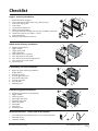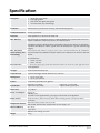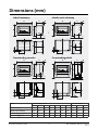
1
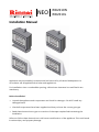
NEO
RIB2310N
RIB2310L
Installation Manual
Appliance must be installed, commissioned and serviced by a licensed tradesperson in
accordance will all applicable local rules and regulations.
For installations into a combustible opening, a Rinnai zero clearance box and flue kit are
mandatory.
Before installation:
• Unpack the appliance and components and check for damage—DO NOT install any
damaged items
• Check all components have been supplied and that you have the correct gas type
• Read these instructions to get an overview of the steps required before starting the
installation
Failure to follow these instructions could cause a malfunction of the appliance. This could result
in serious injury and property damage.
Contents
Checklist
3
Specification
4
Dimensions
5
Location
6
Enclosure dimensions
9
Gas supply
10
Flueing options and components
11
General flueing information
12
Masonry installations
14
Mock chimney installations
16
Freestanding installations
18
Log set installation
20
Granule pack installation
21
Test pressures
22
Checking the flame pattern
24
Fitting the frame assembly
25
Commissioning
26
Wiring diagram
27
WARNING
Improper installation, adjustment, alteration, service or maintenance can cause
property damage, personal injury or loss of life.
For assistance or additional information contact Rinnai on 0800 RINNAI
(0800 746 624).
Checklist
Engine - masonry installation:
1.
2.
3.
4.
5.
6.
7.
8.
9.
10.
1
Rinnai Neo heater (engine)
Outer (attached to heater with 2 x 8 g black screws)
Glass outer dress guard
Inner frame
Log set (inside appliance)
Packet of burner granules
Semi rigid stainless steel gas pipe with 5/8 " UNF flare connection
Flared brass adaptor 5/8 " UNF - ½ " BSPT
Foam sealing strip
Operation and installation manual
2
8
1
4
2
Engine set (see above)
Spigot adaptor
Spigot guide panel
Spigot guide rails
Zero clearance box top panel
Zero clearance box rear panel
Zero clearance box left and right panels
Zero clearance box base panel
Hardware pack
3
A
5
6
8
7
7
1
Engine set (refer masonry installation)
Spigot adaptor
Console top panel
Console right side panel
Console left side panel
Console rear panel
Console pillar
Hardware pack
2
4
A
3
6
8
Engine set (refer masonry installation)
Spigot adaptor
Plinth top panel
Plinth right side panel
Plinth left side panel
Plinth rear panel
Plinth pillar
Plinth base
Hardware pack
1
5
2
4
3
A
7
5
6
Remote/thermostat - comes with all ETR models
1. RF combination remote/thermostatic control with wall mount
2. AA batteries (x2)
3. Operation manual
Rinnai New Zealand Limited
7
6
Freestanding plinth installation:
AA
1.
2.
3.
4.
5.
6.
7.
8.
3
5
Freestanding console installation:
AA
1.
2.
3.
4.
5.
6.
7.
10
5
Inbuilt mock chimney installation:
AA
1.
2.
3.
4.
5.
6.
7.
8.
4
9
3
1
2
3
Neo Installation Manual: 11906-B
02-11
Specification
Description
•
•
•
•
Inbuilt gas space heater
Burning log effect
Glass front with glass dress guard
Convection fan, top air discharge
Installation
Inbuilt masonry, inbuilt mock chimney, and freestanding options
Combustion Method
Bunsen type burner
Data Plate
Inside appliance on the front left hand side
Flue - Masonry
Rinnai strongly recommends the use of a Rinnai flexiliner flue system (flexi Ø 100 mm).
Failure to meet this criteria may result in an unsafe situation.
Installation without a flexiliner flue is permissible as long as the chimney is checked for
soundness and ability to achieve a good draw. Terminal 240 mm x 45 mm rear discharge
(spigot).
Flue - Decorative
(mock chimney) and
Freestanding
Natural draft twin skin flue. An approved 100 mm cowl must be fitted to all installations.
Decorative chimney installations require a Rinnai zero clearance box and zero clearance
flue kit.
Flue dimensions:
• Outer - 150 mm
• Inner - 100 mm
Gas Connection
½ " BSPT, the gas supply terminates inside the heater at the front lower right hand side
of the appliance
Gas Type
NG and General Product LPG
Convection Fan
2-speed centrifugal, double diameter 160 x 180 mm
Heating Area
• Up to 107 m2 (NG)
• Up to 93 m2 (ULPG)
Ignition
Continuous spark electronic ignition
Input/Output
Input NG: 14-30 MJ/h
Input ULPG: 14-27 MJ/h
Noise Level
37-45 dB(A)
Power Consumption
High 50 W
Standby <3 W
1500 mm cord is supplied with 3-pin plug on the rear left of the appliance
Safety Devices
Overheat switch, electrical fuse, flame failure sensing system, and power failure
protection
Temperature Control
Output NG: 3.24-6.94 kW
Output ULPG: 2.98-6.04 kW
Manual models, manual control on unit
ETR models, thermostatic, temperature control range 7-32 °C
Thermal Efficiency
NG - 80.5%
ULPG - 80%
Efficiency star rating: 4.10 stars
Weight
60 kg
Rinnai New Zealand Limited
4
Neo Installation Manual: 11906-B
02-11
Dimensions (mm)
Inbuilt masonry
Inbuilt mock chimney
C
A
B
D
A
F
C
B
F
J
J
E
E
I
G
I
D
H
H
Freestanding console
Freestanding plinth
C
A
D
F
B
C
A
F
B
J
J
E
E
G
I
G
I
H
Model
D
H
External dimensions
Gas connection
A
B
C
D
E
F
G
H
I
J
Inbuilt masonry
865
660
359
62
691
589
-
305
45
235
Inbuilt mock chimney
865
660
363
62
795
650
280
305
45
240
Freestanding console
865
760
363
62
865
760
280
305
140
235
Freestanding plinth
865
837
363
62
865
837
280
305
215
235
Rinnai New Zealand Limited
5
Neo Installation Manual: 11906-B
02-11
Location
The main points governing location are flueing and warm air distribution. The heater must not
be installed where curtains or other combustible materials could come into contact with the
appliance. In some cases curtains may need restraining. The Neo gas fireplace is not designed
to be built into bookcases.
Standard flued appliances draw the air for combustion from the room itself so there is a need
for fixed ventilation. Fixed ventilation must be provided as per NZS 5261.
Clearances
The clearances listed below are minimum clearances unless otherwise stated.
Inbuilt models
Freestanding models (can be positioned directly on the floor)
Rinnai New Zealand Limited
6
Neo Installation Manual: 11906-B
02-11
Location
Mantels, surrounds, and hearths for inbuilt installations
A mantel and surround are allowed providing they are outside the minimum clearances shown
on the previous page.
Minimum clearance
The minimum clearance from the top of the appliance is 400 mm. The depth of the mantel/
surround at this minimum clearance must not exceed 150 mm.
Additional mantel/surround depth
For every 50 mm of added mantel depth/surround, there must be an additional 100 mm of
clearance. For example; a 200 mm mantel depth will require a 500 mm clearance from the top
of the appliance.
Hearths
A hearth is not necessary but can be used for decorative purposes or protection of sensitive
flooring if required. It must not obscure the front of the fire.
Electrical connection
The Neo is supplied with a power cord (length 1500 mm)
and a 3-pin plug. The standard electrical connection passes
through the rear panel, but can also pass through the left
and right hand side of the unit by removing the knockout
tab from the bottom edge of the front panel. If changing
the electrical position use the rubber grommet from the
rear of the appliance for cable protection.
Rinnai recommend the heater is plugged into a dedicated
240 V, 10 A earthed power point. The power point must not
be located above the heater (potential fire hazard). If the
supplied plug and power cord is to be used with an external
power point then the power cord will need to be fitted with
the supplied grommet.
A suitable means of electric isolation must be provided which is adjacent to the appliance and
accessible with the appliance installed.
The electrical cord is not fire rated and should not come into contact with the unit. If the
supply cord is damaged, it must be replaced by a licensed tradesperson. This must be a genuine
replacement part available from Rinnai—part number 6765B.
Rinnai New Zealand Limited
7
Neo Installation Manual: 11906-B
02-11
Location
TV installation above a fireplace
If installing a flat screen TV above the fire the main issue is heat. Heat from the fire and heat
from the flueing components that sit behind the TV, especially if recessed.
The Neo gas fires have a fan that distributes warm air from the top of the appliance out into
the room. As warm air is dispersed outwards as opposed to directly upwards, installation of a
TV may be an option. The diagram below outlines recommended minimum clearances when
installing a TV directly above the Neo inbuilt models. All dimensions are in millimetres.
75
400
400
Mantel
Flue
TV
TV
Flue
20
The 400 mm dimension is the
minimum clearance required
to combustibles and to a
mantel.
200
Rinnai
Neo Inbuilt
Rinnai
Neo Inbuilt
For a TV mounted directly
above the Neo, the mantel
must be at least the depth
of the TV to deflect the heat
away from the appliance.
It is up to the customer to check the TV installation instructions with the TV supplier to verify
clearances. Some TV manufacturers have warranty conditions that state a TV is not to be
installed above a fireplace.
Rinnai does not accept any responsibility for damage to a TV resulting from the use of this
information.
Rinnai New Zealand Limited
8
Neo Installation Manual: 11906-B
02-11
Enclosure dimensions
The enclosure dimensions specified are critical to the successful installation of this appliance.
The appliance must be positioned within the enclosure on a flat level surface. If the appliance is
to be elevated from the ground, a base must be constructed with supporting joists capable of
supporting a minimum of 1.5 times the weight of the appliance.
Inbuilt masonry installations
Inbuilt mock chimney installations
Important
The total cavity depth MUST also include the
thickness of the external cladding as the zero
clearance box MUST BE installed flush with the
cladding surface to ensure alignment of the
flue.
Model
Minimum dimensions (mm)
Height (H)
Width (W)
Depth (D)
Inbuilt masonry
600
695
370
Inbuilt mock chimney
650
800
370
Rinnai New Zealand Limited
9
Neo Installation Manual: 11906-B
02-11
Gas supply
Gas pipe sizing must consider the gas input to this appliance as well as all other gas appliances
in the premises. The gas meter and regulator must be specified for the total gas rate. An
approved sizing chart such as the one in NZS 5261 should be used.
The gas supply termination is inside the heater and enters through the rear of the appliance.
Gas supply location
1 Gas supply location
Mark off the location for the vertical centre line of the heater
enclosure 1 . To the right of the vertical centre line, mark off
the vertical 2 and horizontal 3 locations for the gas supply
penetration.
2
3
Inbuilt
Freestanding
Masonry
Mock Chimney
Console
Plinth
2
305 mm to right of
appliance centre line
305 mm to right of
appliance centre line
265 mm to right of
appliance centre line
305 mm to right of
appliance centre line
3
45 mm from base of
enclosure
45 mm from base of
enclosure
140 mm from floor level
219 mm from floor level
4
Terminate 230 mm from Terminate 230 mm from
front of enclosure
front of enclosure
Terminate at wall
clearance plus 125 mm
Terminate at wall
clearance plus 125 mm
STEP 1
Freestanding installations
TO
ON
FR
The length of the gas supply
termination is measured from the
front of the enclosure.
of
ck
4
5
Ba
LL
WA
cle Min
ara im
nc um
e7
5m
m
OS
UR
E
4
FE
NC
L
E
OF
AR RE
R E OS U
L
NC
he
ate
r
Inbuilt installations
STEP 2
The length of the gas supply
termination is measured from the
back of the heater plus 125 mm.
Installer to terminate to suit, and
fit supplied gas connection 5 .
Leak test the joint between
the flexible gas connection and
termination.
Gas connection:
Gas supply pipe
Installer, terminate to suit
Rinnai New Zealand Limited
Brass adaptor
Flexi
½ ” BSPT
10
Neo Installation Manual: 11906-B
02-11
Flueing options and components
Inbuilt masonry installations
Without flexiliner
Inbuilt mock chimney installations
With flexiliner
A =Direct flue (straight vertical)
B = Offset flue
Freestanding installations
A =Direct flue (straight vertical)
B = Offset flue
Installation
Components available
Part no.
Description
Inbuilt masonry
R1756
R1761
RIB2310 flexi flue kit 4 m
Flexiliner extension 2 m (extends to 3.6 m)
Inbuilt mock chimney,
straight vertical flueing
R2340
R2345
R1762Z
R1763Z
R1763SS
RIB2310 zero clearance box
RIB23 spigot assembly
Flue kit galvanised 3.6 m (same as Timberflame Radius)
Flue extension 1.2 m galvanised
Flue extension 1.2 m stainless steel
R1764
R1766
All of the above components, plus:
45 ° bend kit (same as Timberflame)
Wall penetration kit galvanised (same as Timberflame Radius)
R2345
R1762GL
R1763GL
RIB23 spigot assembly
Freestanding flue kit galvanised black 3.6 m
Freestanding flue extension galvanised black 1.2 m
R1766GL
R1765GL
All of the above components plus:
Freestanding wall penetration kit galaxy black
Freestanding 45 ° bend kit galaxy black
Inbuilt mock chimney,
vertical offset flueing
Freestanding straight
vertical flueing
Freestanding vertical
offset flueing
Rinnai New Zealand Limited
11
Neo Installation Manual: 11906-B
02-11
General flueing information
Every gas fireplace requires a flue system that will draw effectively and clear flue products
safely under all potential wind and climatic conditions. It is the responsibility of the installer to
ensure that the appliance is provided with an effective flue.
For installations requiring a flue, a Rinnai flue system must be used. The flue system must be
fully assembled and secured in place before the appliance is installed.
Flashings
Flashings to the top of chimney structure do not form part of the flue kit and must be specified.
Clearance to combustibles
For installations using the Rinnai zero clearance flue components, the minimum clearance from
inner flue to combustible material must be greater than 50 mm. This equates to 25 mm from
the outer flue when using the Rinnai twin-skin flue.
Flue length and number of bends
Minimum flue length
This is required to ensure adequate draw and prevents spill-back of combustion products which
can cause the safety sensors to shut down the unit.
• minimum flue length before any bends or offsets
• minimum vertical flue length
= 1.0 m
= 3.6 m
Maximum flue length and number of bends
Rinnai recommend a maximum flue length of 8 m with a maximum of two 45° bends.
Self-supporting flue
The weight of the flue system should not be supported by the appliance—it
should be self-supporting. Supporting the flue is usually completed during the
framing stage with flue supports or straps within the cavity.
Rinnai New Zealand Limited
12
Neo Installation Manual: 11906-B
02-11
General flueing information
Shared flues
Gas appliances must not be connected to a chimney or flue serving a separate fuel burning
appliance.
Flue cowl clearance
To ensure products of combustion are cleared, adequate clearance for the building is required
and the below guideline is recommended.
Flue cowl should have a 500
mm clearance from any part of
the building. This also applies
to steeped and pitched roofs
which should be clear of the
ridge line as shown below.
Lesser clearances may provide
perfectly adequate flue systems
depending on the installation.
Minimum clearances are shown
in NZS 5261.
Rinnai New Zealand Limited
13
Neo Installation Manual: 11906-B
02-11
Masonry installations
1. Check dimensions of the opening
Refer 'Enclosure dimensions' and if necessary bring them to the required dimensions.
Check the chimney height as inadequate height can effect product performance. Some
installations may require the chimney height to be extended to reduce down drafts.
2. Check flueway
• Ensure there are no obstructions
• Provide a firm, flat and sealed base (sealed means no holes or openings in the fireplace)
• Ensure adequate support of the appliance (if not properly supported noise and vibration
may result)
3. Install flexiliner flue system
To ensure adequate draw for maximum performance of the appliance, Rinnai strongly
recommends the use of a Rinnai flexiliner flue system for masonry installations. Failure to meet
this installation criteria may result in an unsafe situation. Performance issues resulting from
inadequate flueing is not covered by the warranty.
Installation without a flexiliner is permissible in masonry installations as long as the chimney
has been checked for soundness and ability to achieve a good draw.
Masonry
installation
without aa flexiliner
flexiliner flue
Inbuilt
masonry without
Inbuilt masonry
with
a flexiliner
flue
Masonry
installation
with
a flexiliner
flue
Approved chimney
cowl
Approved chimney
cowl
Chimney plate
Mortar
Chimney plate
Minimum
200 mm
Minimum
3.6 m
Mortar
Adaptor
Minimum
200 mm
Minimum
3.6 m
Flexible chimney
liner
Appliance
adaptor
Rinnai New Zealand Limited
14
Neo Installation Manual: 11906-B
02-11
Masonry installations
4.Installing the heater into the fireplace
Apply the supplied foam seal strip to the rear of the heater. The strip is intended to form a seal
between the heater and the fireplace. If an adequate seal cannot be formed with this strip
another means of sealing must be used (non-combustible insulation) between the fireplace and
the heater body.
If using a flexiliner flue, prepare the heater engine by drilling four x Ø 3.2 mm holes in the prepressed dimples on the top panel of the heater. Attach the flue guide rails from the flue kit
using the supplied screws. Align the guide rails with the guide plate and slide the heater engine
into the enclosure until the guide plate is fully against the rear of the front assembly-this will
ensure the heater and flue spigot are correctly aligned.
Carefully move the appliance into the enclosure ensuring the gas supply feeds into the rear
access hole and fasten heater to the fireplace.
Guide rails
Flue guide rails
Guide plate
Rear of front
assembly
Drill
4 x Ø 3.2mm
holes
Rinnai New Zealand Limited
15
Neo Installation Manual: 11906-B
02-11
Mock chimney installations
For installations into a mock chimney a Rinnai zero clearance box and zero clearance flue kit is
required to isolate the appliance from combustible materials. Failure to meet this installation
criteria will void any product warranty.
1. Construct frame and install zero clearance box
Refer 'Enclosure dimensions' and construct frame. Assemble and install the RIB2310 zero
clearance box. Installation needs to be on a level base. If this is not done the appliance may
twist and become damaged—this will void any product warranty.
650 mm min.
The zero clearance box is installed flush with the cladding surface.
.
in
0
37
m
m
m
7
800 m
m
2. Install the flue and complete electrical connection
The weight of the flue system should not be supported by the appliance—it should be selfsupporting. Supporting the flue is usually completed during the framing stage with flue
supports or straps within the cavity. Flue supports have been included with the flue kit to assist
with this. These are to be riveted to the flue.
Please note, a twin-skin flue requires a 25 mm clearance (from the outer flue) from
combustibles.
Inner flue 100 mm
Flue
Outer flue 150 mm
Combustible Material
(must be greater than 50 mm from inner flue)
Rinnai New Zealand Limited
16
Neo Installation Manual: 11906-B
02-11
Mock chimney installations
Flue cowl
50 mm
Clamping spacer
Sealing collar
(not supplied)
Twin-skin flue
Outer flue 150 mm
Bring the flue down within 50 mm of the unit and then
use the slip collar provided in the flue kit.
Inner flue 100 mm
Any residual heat in the zero clearance box is ducted
away via the outer flue
3. Installing the heater into the fireplace
Carefully move the appliance into the enclosure ensuring the gas supply feeds into the rear
access hole and fasten heater to the fireplace with the four fixings either side of the unit as
shown below.
Rinnai New Zealand Limited
17
Neo Installation Manual: 11906-B
02-11
Freestanding installations
While the following diagrams depict the Neo Freestanding Console model, the steps to
constructing the Neo Freestanding Plinth are the same.
1. Attach the flue spigot to the Neo engine
Using a 3.3 mm drill bit, drill through the four dimples at the rear of the back panel of the Neo
engine. Attach the flue spigot (ordered separately) with the screws provided.
Attach flue spigot
2. Assemble, position and secure base assembly to the floor
Assemble the base assembly provided in the Neo freestander kit and place on the floor where
the Neo is to be located. Using three appropriate bolts or screws secure the base assembly to
the floor. This also acts as a seismic constraint.
The diagram below shows the base assembly for the Neo Console model. The Neo Plinth base
assembly has a pillar section attached.
Fixing positi
Rinnai New Zealand Limited
ons
18
Neo Installation Manual: 11906-B
02-11
Freestanding installations
3. Attach heater to base assembly and fit back panel
Lift the Neo freestanding engine into position over the base assembly and fix into position
using the four M5 x 10 screws supplied.
Remove the three screws from the base of the unit (do not discard) and screw the back
freestanding panel into position—nine screws in total.
1
4
2
5
3
6
Three screws from unit base (screws 7,8 & 9)
Four screw positions for
securing the unit to the
base assembly
4. Add top and side panels
Install the freestanding top panel using three M5 x 10 and three self tapping screws. Install the
freestanding side panels (ensure you push up to minimise the gap) using six screws per side.
M5 x 10 screws
Self tapping screws
Minimise
gap
Screw positions for
side panels
Rinnai New Zealand Limited
19
Neo Installation Manual: 11906-B
02-11
Log set installation
The granule pack and log set, consisting of five log
pieces, comes packaged inside the appliance, you will
need to remove the glass retainer (four screws) before
installing the granules and log set. Use extreme care
when handling the log pieces, they are made from a
fragile material and will damage easily.
It is important you position the pieces in the order
shown below. Incorrect placement can create carbon build up and effect performance.
Malfunctioning due to improper log placement is not covered under warranty. The unit must
never be used with broken logs and should not be mixed with other burn media (except the
Rinnai Neo granules).
1. Check to ensure that the ports of the main
burner are clean and clear of any particles and all
packaging.
2. Select the thicker ‘Y’ log and fit into position by
lining up the two pin holes onto the two pins of
the locating bracket that is fixed to the centre of
the main burner.
1
3. Select the thick straight log and fit onto the
metal locators on the left rear of the panel. When
correctly located this log will be touching the
burner box walls.
4. Select the thinner ‘Y’ log and fit into position by
linking up the two pin holes onto the two pins of
the first two logs. Ensure this log is seated all the
way down until it touches logs 1 and 2.
2
3
1
1
2
5. Select the longest log and fit onto the metal
locators at the right rear of the panel. When
correctly located this log will be touching the
burner box walls and resting on log 1.
6. Locate the final bowed log onto the metal locater
at the base of the right side panel and the bracket
fixed to the main burner. Lean the log back until
it rests on log 4.
3
4
4
1
Rinnai New Zealand Limited
20
Neo Installation Manual: 11906-B
02-11
Granule pack installation
The granules as well as being added to create a more realistic log flame effect (by
diffusing the gas flames through the burner ports) also assist in soot prevention and
are CRITICAL to the performance of the heater.
Never pour the granules directly from the pack as dust particles from the plastic bag
may block the ports.
NG installations
Place the granules evenly across the burner—use the whole pack.
ULPG installations
Carefully place 30 of the granules as close as possible to the front burner ports as shown on
the diagram below. DO NOT cover any of the front right side ports. It’s important this is done
correctly as incorrect placement can cause high yellow flames (dirty combustion) that may
cause sooting.
It is desirable that the flames touch the granules as this diffuses any ‘candling’ effect and
enhances the realistic log burning look of the heater.
Rinnai New Zealand Limited
21
Neo Installation Manual: 11906-B
02-11
Test pressures
To check and set the burner pressures
1. Refer to the data plate located inside the appliance on the front left hand side for the
correct gas pressure settings.
2. Using a screw driver loosen the captive Appliance Test Point Pressure Screw (ATPP) and fit
the manometer.
3. Remove the dust cap from the regulator adjusting nut and screw.
Gas control valve
High pressure
adjusting nut
Gas
inlet
Low pressure
adjusting screw
Inlet test
point
Gas outlet
Appliance test point
pressure
Cap
Gas control power connection
Rinnai New Zealand Limited
22
Neo Installation Manual: 11906-B
02-11
Test pressures
High pressure setting
4. Turn the appliance on and set the heater to its highest setting (refer operation manual).
Using a screw driver hold the low pressure adjusting screw stationary while adjusting the
high pressure setting nut with a 10 mm spanner. Turning the nut clockwise will increase the
outlet pressure while turning the nut anti-clockwise will decrease the outlet pressure.
Low pressure setting
5. Disconnect the power to the Gas Control Valve (GCV) by separating the connector for the
power supply (yellow wires). The GCV will automatically default to low pressure operation.
Using a 10 mm spanner hold the high pressure adjusting nut stationary while adjusting
the low pressure screw with a screw driver. Turning the screw clockwise will increase the
outlet pressure while turning the screw anti-clockwise will decrease the outlet pressure.
6. Replace the dust cap to its original position. It’s important this is done correctly to ensure
the correct operation of the GCV.
7. Reconnect the power to the GCV by rejoining the connector (yellow wires).
8. After confirming the correct pressures, turn the appliance off, remove the manometer,
tighten the ATPP sealing screw and leak test.
9. Turn the appliance on and off a few times to check ignition.
10. When you are satisfied that the heater is working correctly, reassemble and start the
appliance to check the flame pattern (refer next page).
High pressure
adjusting nut
Increase
Low pressure
adjusting screw
Increase
Decrease
Appliance test
point pressure
Decrease
Cap
POV power connector
Rinnai New Zealand Limited
23
Neo Installation Manual: 11906-B
02-11
Checking the flame pattern
It may take approximately two hours of operation for the logs to achieve their full flame
pattern and glow. During the initial burning in period, some smoke and smell may be
experienced. The appliance should be run on the high setting in a well ventilated room until
these dissipate. It is important to check the flame pattern during this time.
Abnormal flame pattern
Abnormal flame performance and/or pattern can indicate a problem with the fire, such as
blocked gas injectors, log movement during installation or incorrect flue installation. There are
some warning signs that could indicate a problem.
•
•
•
•
•
Unusual smell from the appliance
Continued difficulty or delay in establishing a flame
Flame appears either very short or very long
Flame only burns part way across the burner
Severe soot building up on the inside of the glass door
Normal flame pattern
Abnormal flame pattern
Soot build up
It is the responsibility of the installer to check that under normal conditions of the
appliance, all flue gases are exhausted to the outside atmosphere and that there are no
spillage of combustion gases into the room.
If the appliance cannot be made to perform correctly, please contact Rinnai.
Rinnai New Zealand Limited
24
Neo Installation Manual: 11906-B
02-11
Fitting the frame assembly
Before fitting the frame assembly, ensure that it is not scratched or damaged in any way. The
frame assembly comes packaged in one box and contains the outer frame, glass dress guard
and inner frame.
NOTE
When placing the assembly down ensure it is placed on its lower edge or flat. If it is
placed on its left or right edge the glass may slide out off the stand-off posts. If this
should occur ensure that the silicon rubber mounts are not dislodged when sliding the
glass back into position.
1. Before installing the frame assembly remove the two black screws that are already
positioned in the appliance. These are located on the bottom of the unit, one each side.
2. Take the inner frame and hook the slanted edge (bottom is flat) over the top of the glass
retainer brackets and swing down into position onto the magnets.
3. Carefully lift the outer frame assembly complete with glass dress guard, taking care not
to tilt it on its edge as the glass may slide out off the stand-off posts. Come in close to the
heater and plug in the CAT cable into the control panel.
Position of the CAT cable and control panel plug (step 3)
CAT cable
Control panel
plug
Rinnai New Zealand Limited
25
Neo Installation Manual: 11906-B
02-11
Fitting the frame assembly
4. Lift and slot the assembly over the top and swing down, the lower screws need to be
positioned over and inside the bottom flange.
5. Push the outer frame assembly into position and screw in place with the two screws
removed in step 1.
Fitting the frame (steps 4 and 5), ensure you do not place excessive tension or pinch the CAT cable
CAT cable
Position of black screws
Fascia assembly
Rear view of fascia
for reference
Commissioning
Complete the installation and commissioning checklist in the customer operation manual and
make sure you leave the manual with the customer.
Explain to the customer about the use and care of the unit and that they understand the
instructions.
Rinnai New Zealand Limited
26
Neo Installation Manual: 11906-B
02-11
Wiring diagram
Rinnai New Zealand Limited
27
Neo Installation Manual: 11906-B
02-11
Address:
105 Pavilion Drive, Mangere, Auckland
PO Box 53177, Auckland Airport, Auckland 2150
0800:
Phone:
0800 RINNAI (746 624)
(09) 257 3800
Fax:
(09) 257 3899
Email:
[email protected]
Website:www.rinnai.co.nz
All Rinnai appliances meet or exceed the safety standards required by New Zealand
gas and electrical regulations.
Rinnai is constantly improving its products and as such information and
specifications are subject to change or variation without notice.