1
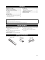
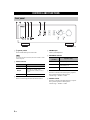
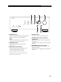
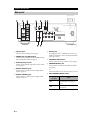
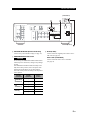
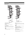
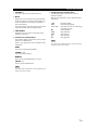
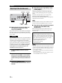
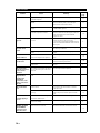
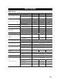
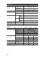
AB
Integrated Amplifier
OWNER’S MANUAL
CAUTION: READ THIS BEFORE OPERATING YOUR UNIT.
CAUTION: READ THIS BEFORE OPERATING YOUR UNIT.
1
2
3
4
5
6
7
8
9
10
11
12
13
14
15
16
To assure the finest performance, please read this manual
carefully. Keep it in a safe place for future reference.
Install this sound system in a well ventilated, cool, dry,
clean place - away from direct sunlight, heat sources,
vibration, dust, moisture, and/or cold. For proper
ventilation, allow the following minimum clearances
around this unit.
Top: 30 cm
Rear: 20 cm
Sides: 20 cm
Locate this unit away from other electrical appliances,
motors, or transformers to avoid humming sounds.
Do not expose this unit to sudden temperature changes
from cold to hot, and do not locate this unit in an
environment with high humidity (i.e. a room with a
humidifier) to prevent condensation inside this unit,
which may cause an electrical shock, fire, damage to this
unit, and/or personal injury.
Avoid installing this unit where foreign object may fall
onto this unit and/or this unit may be exposed to liquid
dripping or splashing. On the top of this unit, do not
place:
– Other components, as they may cause damage and/or
discoloration on the surface of this unit.
– Burning objects (i.e. candles), as they may cause fire,
damage to this unit, and/or personal injury.
– Containers with liquid in them, as they may fall and
liquid may cause electrical shock to the user and/or
damage to this unit.
Do not cover this unit with a newspaper, tablecloth,
curtain, etc. in order not to obstruct heat radiation. If the
temperature inside this unit rises, it may cause fire,
damage to this unit, and/or personal injury.
Do not plug in this unit to an AC wall outlet until all
connections are complete.
Do not operate this unit upside-down. It may overheat,
possibly causing damage.
Do not use force on switches, knobs and/or cords.
When disconnecting the power cable from the AC wall
outlet, grasp the plug; do not pull the cable.
Do not clean this unit with chemical solvents; this might
damage the finish. Use a clean, dry cloth.
Only voltage specified on this unit must be used. Using
this unit with a higher voltage than specified is dangerous
and may cause fire, damage to this unit, and/or personal
injury. Yamaha will not be held responsible for any
damage resulting from use of this unit with a voltage
other than specified.
To prevent damage by lightning, keep the power cable
and outdoor antennas disconnected from an AC wall
outlet or this unit during a lightning storm.
Do not attempt to modify or fix this unit. Contact
qualified Yamaha service personnel when any service is
needed. The cabinet should never be opened for any
reasons.
When not planning to use this unit for long periods of
time (i.e. vacation), disconnect the AC power plug from
the AC wall outlet.
Be sure to read the “TROUBLESHOOTING” section on
common operating errors before concluding that this unit
is faulty.
i En
17 Before moving this unit, press A (power) to set this unit
to standby mode, and then disconnect the AC power plug
from the AC wall outlet.
18 Condensation will form when the surrounding
temperature changes suddenly. Disconnect the power
cable from the outlet, then leave this unit alone.
19 When using this unit for a long time, this unit may
become warm. Turn the power off, then leave this unit
alone for cooling.
20 Install this unit near the AC wall outlet and where the AC
power plug can be reached easily.
21 The batteries shall not be exposed to excessive heat such
as sunshine, fire or the like.
22 Excessive sound pressure from earphones and
headphones can cause hearing loss.
This unit is not disconnected from the AC power source as long as
it is connected to the AC wall outlet, even if this unit itself is turned
off by A. This state is called the standby mode. In this state, this
unit is designed to consume a very small quantity of power.
WARNING
TO REDUCE THE RISK OF FIRE OR ELECTRIC SHOCK, DO
NOT EXPOSE THIS UNIT TO RAIN OR MOISTURE.
This label is required to be attached to a product of which
the temperature of the top cover may be hot during
operation.
■ For U.K. customers
If the socket outlets in the home are not suitable for the
plug supplied with this appliance, it should be cut off and
an appropriate 3 pin plug fitted. For details, refer to the
instructions described below.
Note
The plug severed from the mains lead must be destroyed,
as a plug with bared flexible cord is hazardous if engaged
in a live socket outlet.
■ Special Instructions for U.K. Model
IMPORTANT
THE WIRES IN MAINS LEAD ARE COLOURED IN
ACCORDANCE WITH THE FOLLOWING CODE:
Blue: NEUTRAL
Brown: LIVE
As the colours of the wires in the mains lead of this apparatus may
not correspond with the coloured markings identifying the
terminals in your plug, proceed as follows:
The wire which is coloured BLUE must be connected to the
terminal which is marked with the letter N or coloured BLACK.
The wire which is coloured BROWN must be connected to the
terminal which is marked with the letter L or coloured RED.
Make sure that neither core is connected to the earth terminal of the
three pin plug.
CONTENTS
USEFUL FEATURES ................................... 1
SUPPLIED ACCESSORIES......................... 1
CONTROLS AND FUNCTIONS................. 2
Front panel ........................................................2
Rear panel .........................................................4
Remote control..................................................6
PLAYBACK................................................. 11
Playing a source ............................................. 11
Adjusting to the desired sound ....................... 12
TROUBLESHOOTING.............................. 13
SPECIFICATIONS ..................................... 15
CONNECTIONS............................................ 9
Connecting speakers and source components...9
Connecting power cable..................................10
About this manual
• y indicates a tip for your operation.
• The illustrations used in this Owner’s Manual are A-S701.
• Depending on the model, there are some countries/regions where it may not be sold.
USEFUL FEATURES
This unit allows you to:
◆ Enjoy the highest sound quality of compact discs by
using the CD direct function (A-S701 only)
(see page 12)
◆ Enjoy pure, high fidelity sound by using the Pure
Direct function (see page 12)
◆ Save power by using AUTO POWER STANDBY
switch (see page 4)
◆ Use the remote control of this unit to operate a Yamaha
tuner and/or CD player (see page 7)
◆ Boost bass sounds by connecting a subwoofer
(see page 9)
SUPPLIED ACCESSORIES
Please check that you received all of the following parts.
Remote control
Batteries (x2)
(AA, R6, UM-3)
Power cable
(A-S701 only)
1 En
CONTROLS AND FUNCTIONS
Front panel
(A-S701)
1
A (power) switch
Turns on and off the power of this unit.
4 PHONES jack
Connect your headphones.
Note
5 SPEAKERS selector
Even when this unit is turned off, this unit consumes a small
amount of power.
2 Power indicator
Indicator
Status
Brightly lit
The power of this unit is “on”.
Dimly lit
This unit is in “standby” mode.
For details on the “standby” mode, see
page 6.
Off
The power of this unit is “off”.
3 Remote control sensor
Receives infrared signals from the remote control.
2 En
Selector
position
Speaker status
OFF
Both sets of speakers are off.
A or B
The set of speakers connected to the A
or B terminals is on.
A+B BI-WIRING
Both sets of speakers are on.
6 BASS control
Increases or decreases the low frequency response.
The 0 position produces a flat response.
Control range: –10 dB to +10 dB
7 TREBLE control
Increases or decreases the high frequency response.
The 0 position produces a flat response.
Control range: –10 dB to +10 dB
CONTROLS AND FUNCTIONS
(A-S701)
8 BALANCE control
Adjusts the sound output balance of the left and right
speakers to compensate for sound imbalances.
Note
If you rotate the BALANCE control to the end of L (left) or
R (right), the opposite side of channel is muted.
9 LOUDNESS control
Retain a full tonal range at any volume level
(see page 12).
0 INPUT selector and indicators
Selects the input source you want to listen to. The
input source indicators light up when the
corresponding input sources are selected.
A VOLUME control
Increases or decreases the sound output level.
B CD DIRECT AMP button and indicator
(A-S701 only)
Reproduces CD sound in the highest signal quality
(see page 12).
The indicator above it lights up when this function is
turned on.
C PURE DIRECT button and indicator
Reproduces any input source in the purest sound
possible (see page 12).
The indicator above it lights up when this function is
turned on.
y
The input source names correspond to the names of the
connection jacks on the rear panel.
3 En
CONTROLS AND FUNCTIONS
Rear panel
(A-S501/S301)
(A-S701)
1 CD input jacks
Used to connect a CD player (see page 9).
2 PHONO jacks and GND terminal
Used to connect a turntable that uses an MM cartridge,
and to ground the terminal (see page 9).
3 Audio input/output jacks
Used to connect external components, such as a tuner,
etc (see page 9).
4 DIGITAL (OPTICAL) jack
Used to connect a component with a digital optical
output (see page 9).
5 DIGITAL (COAXIAL) jack
Used to connect a component with a digital coaxial
output (see page 9).
4 En
6 DC OUT jack
For supplying power to a Yamaha AV accessory. For
details on connections, refer to the instruction manual
of the AV accessory.
7 SPEAKERS A/B terminals
Used to connect one or two speaker sets (see page 9).
8 SUBWOOFER OUT jack
Used to connect a subwoofer with built-in amplifier
(see page 9).
y
The SUBWOOFER OUT jack attenuates signals over 90 Hz.
9 AUTO POWER STANDBY switch
Switch
position
Status
ON
The unit enters standby mode
automatically if not operated for 8
hours.
OFF
The unit does not enter standby mode
automatically.
CONTROLS AND FUNCTIONS
(A-S501/S301)
(A-S701)
0 VOLTAGE SELECTOR (General model only)
Used to set to your local main voltage (see page 10).
A IMPEDANCE SELECTOR switch
CAUTION
Do not change the IMPEDANCE SELECTOR switch
while the power is turned on, as doing so may damage
the unit.
If the IMPEDANCE SELECTOR switch may not be
fully slid to either position, remove the power cable
and slide the switch all the way to either position.
Select the switch position according to the impedance
of the speakers.
Speaker
connection
Speaker
impedance
Power cable (A-S501/S301)
Used to connect this unit to an AC wall outlet
(see page 10).
Switch
position
SPEAKERS A
or
SPEAKERS B
6 Ω or higher
HIGH
4 Ω or higher
LOW
SPEAKERS A
and
SPEAKERS B
12 Ω or higher
HIGH
8 Ω or higher
LOW
6 Ω or higher
HIGH
4 Ω or higher
LOW
Bi-wiring
B AC IN (A-S701)
Used to connect the supplied power cable to an AC
wall outlet (see page 10).
5 En
CONTROLS AND FUNCTIONS
Remote control
(A-S701)
1 Infrared signal transmitter
Sends infrared signals.
2
A AMP
Turns this unit on, or sets it to standby mode.
3
OPEN/CLOSE
Opens/closes the disc tray of the Yamaha CD player.
Refer to the owner’s manual of your CD player for
details.
Note
Even when using a Yamaha CD player, certain components
and features may not be available.
(A-S501/S301)
4
A CD
Turns the Yamaha CD player on, or sets it to standby
mode. Refer to the owner’s manual of your CD player
for details.
Note
Even when using a Yamaha CD player, certain components
and features may not be available.
5 CD DIRECT AMP (A-S701 only)
Reproduces CD sound in the highest signal quality
(see page 12).
6 Input selector buttons
Selects the input source you want to listen to.
y
The input source names correspond to the names of the
connection jacks on the rear panel.
6 En
CONTROLS AND FUNCTIONS
7 VOLUME +/–
Increases or decreases the sound output level.
8 MUTE
Reduces the current volume level by approximately
20 dB. Press again to restore the audio output to the
previous volume level. Pressing the VOLUME +/–
also cancels muting.
The input indicator on the front panel for the current
input source blinks while the output is muted.
9 PURE DIRECT
Reproduces any input source in the purest sound
possible (see page 12).
0 Yamaha tuner control buttons
The following buttons can be used to control various
functions of a Yamaha tuner.
Refer to your component’s owner’s manual for more
information.
A Yamaha CD player control buttons
The following buttons can be used to control a
Yamaha CD player.
Refer to your component’s owner’s manual for more
information.
w
f
DISC SKIP
e
b
a
p
s
Rewinds playback
Fast-forwards playback
Skips to the next disc in a CD changer
(A-S501/S301 only)
Pauses playback
Skips backward
Skips forward
Starts playback
Stops playback
Note
Even when using a Yamaha CD player, certain components
and features may not be available.
BAND
Selects the reception band (FM/AM).
TUNING jj / ii
Selects the tuning frequency.
MEMORY
Stores the current FM/AM station as a preset.
PRESET j / i
Selects a preset FM/AM station.
Note
Even when using a Yamaha tuner, certain components and
features may not be available.
7 En
CONTROLS AND FUNCTIONS
■ Installing batteries
AA, R6, UM-3 batteries
■ Operation range
Point the remote control at the remote control sensor on
this unit and remain within the operating range shown
below.
Approximately
6m
Remote control
■
•
•
•
•
•
•
•
•
•
•
•
•
Notes on remote control and batteries
The area between the remote control and this unit must be clear of large obstacles.
Be careful not to spill water or other liquids on the remote control.
Be careful not to drop the remote control.
Do not leave or store the remote control in the following conditions:
– places of high humidity, such as near a bathroom
– places of high temperatures, such as near a heater or stove
– places of extremely low temperatures
– dusty places
Change all batteries if you notice the operation range of the remote control narrows.
If the batteries run out, immediately remove them from the remote control to prevent an explosion or acid leak.
If you find leaking batteries, discard the batteries immediately, taking care not to touch the leaked material. If the leaked material
comes into contact with your skin or gets into your eyes or mouth, rinse it away immediately and consult a doctor. Clean the battery
compartment thoroughly before installing new batteries.
Do not use old batteries together with new ones. This may shorten the life of the new batteries or cause old batteries to leak.
Do not use different types of batteries (such as alkaline and manganese batteries) together. Batteries that look the same may have a
different specification.
Dispose of batteries according to your regional regulations.
Keep the batteries in a location out of reach of children.
Batteries can be dangerous if a child were to put in his or her mouth.
If you plan not to use this unit for a long period of time, remove the batteries from this unit. Otherwise, the batteries will wear out,
possibly resulting in a leakage of battery liquid that may damage this unit.
8 En
CONNECTIONS
Connecting speakers and source components
Make sure to connect L (left) to L, R (right) to R, “+” to “+” and “–” to “–”. If the connections are faulty, no sound will
be heard from the speakers, and if the polarity of the speaker connections is incorrect, the sound will be unnatural and
lack bass. Refer to the owner’s manual for each of your components.
Make sure to use RCA cables or optical cable to connect audio components.
CAUTION
Do not connect this unit or other components to the main power until all connections between components are complete.
Turntable
DVD player,
etc.
Tuner
Audio
out
GND
Audio
out
CD player
Speakers A
Right
Left
TV, etc.
Audio
out
Audio
out
Audio
out
Audio
In
Tape deck,
etc.
BD player, etc.
Audio
out
Audio
In
Audio
out
Audio
out
CD recorder,
etc.
Subwoofer
Right
Left
Speakers B
Only PCM signals can be input to the DIGITAL (OPTICAL/COAXIAL) jacks of this unit. For details on the supported
PCM signals, see page 15.
y
• The PHONO jacks are designed for connecting a turntable with an MM cartridge.
• Connect your turntable to the GND terminal to reduce noise in the signal. However, for some turntables, you may hear less noise
without the GND connection.
9 En
CONNECTIONS
■ REC jacks
Rear panel
• The audio signals are not output via the LINE 2 REC
or LINE 3 REC output jacks when LINE 2 or LINE 3
is selected with the INPUT selector.
• The VOLUME, BASS, TREBLE, BALANCE and
LOUDNESS controls and the CD DIRECT function
(or the PURE DIRECT function) have no effect on the
source being recorded.
Speaker
■ Connecting speaker cables
1 Remove approximately 10 mm of insulation from the
end of each speaker cable.
2 Twist the bare wires of the cable firmly together.
3 Unscrew the knob.
4 Insert one bare wire into the hole in the side of each
terminal.
5 Tighten the knob to secure the wire.
Connect the other speaker to the other set of terminals in
the same way.
Note
When making bi-wire connections, remove the shorting bridges
or cables on the speaker. Refer to the speakers’ instruction
manuals for more information.
y
To use the bi-wire connections, set the SPEAKERS selector on
the front panel to the A+B BI-WIRING position.
10 mm
Red: positive (+)
Black: negative (–)
Connecting power cable
CAUTION
CAUTION
• Set the IMPEDANCE SELECTOR switch according to
the impedance of the speakers to be connected (see
page 5).
• Do not let bare speaker wires touch each other or any
metal part of this unit. This could damage this unit and/
or the speakers.
■ Connecting via banana plug
(North America, General, China and
Australia models only)
1 Tighten the knob.
2 Insert the banana plug into the end of the
corresponding terminal.
Banana plug
■ Bi-wire connection
In the case of speakers supporting the bi-wiring
connection, the tweeter/midrange unit and woofer of the
speakers can be driven independently through connections
shown in the following figure, allowing you to enjoy clear
mid- and high-range sounds.
10 En
(General model only)
Before connecting the power cable, make sure you set
VOLTAGE SELECTOR of this unit according to your
local voltage. Improper setting of VOLTAGE SELECTOR
may cause fire and damage to this unit.
■ AC IN (A-S701)
Connect the supplied power cable to AC IN after all other
connections are complete.
■ Power cable (A-S501/S301)
Connect the power cable to an AC wall outlet after all
other connections are complete.
To the AC
wall outlet
(A-S501/S301)
To the AC
wall outlet
(A-S701)
PLAYBACK
Playing a source
SPEAKERS
4
VOLUME
Rotate the SPEAKERS selector on the front
panel to select SPEAKERS A, B or A+B BIWIRING.
y
Set the SPEAKERS selector to the A+B BI-WIRING position
when two sets of speakers are connected using bi-wire
connections, or when using two sets of speakers simultaneously
(A and B).
(A-S701)
A
5
Play the selected input source.
6
Rotate the VOLUME control on the front
panel (or press VOLUME +/– on the remote
control) to adjust the sound output level.
INPUT
A AMP
Input selector
buttons
y
You can adjust to the desired sound by using the BASS,
TREBLE, BALANCE and LOUDNESS controls, the CD
DIRECT AMP button, or the PURE DIRECT button on the front
panel.
7
When finished listening, press A (power)
switch on the front panel outward to turn off
this unit.
y
VOLUME +/–
1
Rotate the VOLUME control on the front
panel fully counter-clockwise so as not to
play sounds loud suddenly.
2
Press A (power) switch on the front panel
inward to turn on this unit.
3
Rotate the INPUT selector on the front panel
(or press one of the Input selector buttons on
the remote control) to select the input source
you want to listen to.
The indicator for the selected input source lights up.
If A AMP on the remote control is pressed while the A (power)
switch on the front panel is in the on position, this unit enters
standby mode. Press A AMP again to turn this unit on.
11 En
PLAYBACK
Adjusting to the desired sound
LOUDNESS
VOLUME
■ Reproducing pure, high fidelity sound
(PURE DIRECT)
When the PURE DIRECT function is on, noise can be
reduced by bypassing the circuit that the audio input
signal is not using and stopping the power supply to the
circuit.
Therefore, in all input sources, you can enjoy music
playback in straight and high quality sound.
The indicator above the PURE DIRECT button lights up
when this function is turned on.
Note
(A-S701)
CD DIRECT
AMP
PURE
DIRECT
■ Making it easier to hear the high- and
low-frequency ranges even at low
volume (LOUDNESS)
Enjoy natural sound even at low volume by lowering the
mid-range sound level and compensating for the human
ears’ loss of sensitivity to high- and low-frequency ranges
at low volume.
CAUTION
If the CD DIRECT AMP function (or the PURE DIRECT
function) is turned on with the LOUDNESS control set at
a certain level, the input signals bypass the loudness
control, resulting in a sudden increase in the sound output
level. To prevent your ears or the speakers from being
damaged, be sure to press the CD DIRECT AMP button
(or the PURE DIRECT button) AFTER lowering the
sound output level or AFTER checking that the
LOUDNESS control is properly set.
1
Set the LOUDNESS control to the FLAT
position.
2
Rotate the VOLUME control on the front
panel (or press VOLUME +/– on the remote
control) to set the sound output level to the
loudest listening level that you would listen
to.
3
Rotate the LOUDNESS control
counterclockwise until the desired volume is
obtained.
12 En
The BASS, TREBLE, BALANCE and LOUDNESS controls do
not function while the PURE DIRECT function is turned on.
■ Reproducing CD sound with the highest
sound quality (CD DIRECT AMP)
(A-S701 only)
When selecting the input source other than CD, if you
press the CD DIRECT AMP button, the input source
switches to CD.
CD Direct Amp feature
Stop power supply to the unnecessary circuit for CD
playback, convert the input signal to the normal phase
and reverse phase, and balance transfer to the electronic
volume. With the following effects, a more faithful
sound to the original will be provided.
• improved signal-to-noise ratio
• external noise canceling
• reduced distortion
Notes
• The BASS, TREBLE, BALANCE and LOUDNESS controls do
not function while the CD DIRECT AMP function is turned on.
• Be sure to connect the CD player to the CD input jacks if you
use the CD direct function.
• The CD DIRECT AMP function is turned off if the following
operation is performed.
– Select an input source other than CD for the INPUT selector.
– The PURE DIRECT function is turned on.
TROUBLESHOOTING
Refer to the chart below if this unit does not function properly. If the problem you are experiencing is not listed below or
if the instructions below do not help, turn off this unit, disconnect the power cable, and then contact the nearest
authorized Yamaha dealer or service center.
Problem
This unit fails to turn
on.
This unit turns off
suddenly and the
power indicator
blinks.
Cause
See
page
The power cable is not connected or the
plug is not completely inserted.
Connect the power cable firmly.
The A AMP is pressed on the remote
control while this unit is turned off.
Press A (power) switch on the front panel to on.
The impedance setting of the connected
speaker is too small.
Use speaker(s) with proper speaker impedance.
The protection circuitry has been activated
because of a short circuit, etc.
Check that the speaker wires are not touching each
other and then turn the power of this unit back on.
10
There is a problem with the internal
circuitries of this unit.
Disconnect the power cable and contact the nearest
authorized Yamaha dealer or service center.
—
The speaker wires are touching each other
or shorting out against the rear panel.
Connect the speaker cables properly and press the A
(power) switch again. The INPUT indicators blink
and the volume is decreased to the lowest setting
automatically, then the INPUT indicators stop
flashing and the last input source selected lights up.
Confirm normal sound output from speakers by
increasing the volume gradually.
10
Replace the speaker set and press the A (power)
switch again. The INPUT indicators blink and the
volume is decreased to the lowest setting
automatically, then the INPUT indicators stop
flashing and the last input source selected lights up.
Confirm normal sound from speakers by increasing
the volume gradually.
—
The protection circuitry has been activated
because of excessive input or excessive
volume level.
Rotate the VOLUME control on the front panel to
decrease the volume level and then turn the power on
again.
—
The protection circuitry has been activated
due to excessive internal temperature.
Allow about 30 minutes for the temperature inside
this unit to decrease, rotate the VOLUME control on
the front panel to lower the volume and then turn the
power on again. Set the unit in a place where heat can
readily dissipate from the unit.
—
The IMPEDANCE SELECTOR switch is
not fully slid to either position.
Turn the power off and slide the IMPEDANCE
SELECTOR switch all the way to the correct position.
5
The IMPEDANCE SELECTOR switch is
not set to the correct position.
Set the IMPEDANCE SELECTOR switch to the
position that corresponds to the impedance of your
speakers.
5
This unit has been exposed to a strong
external electric shock (such as lightning
or strong static electricity).
Turn off this unit, disconnect the power cable, plug it
back in after 30 seconds, then use the unit normally.
There is a problem with the internal
circuitries of this unit.
Disconnect the power cable and contact the nearest
authorized Yamaha dealer or service center.
—
Sound is muted.
Press MUTE on the remote control or rotate the
VOLUME control.
7
Incorrect cable connections.
Connect the stereo cable for audio units and the
speaker wires properly. If the problem persists, the
cables may be defective.
9
The speaker is malfunctioning.
No sound.
Remedy
10
2
5
—
13 En
TROUBLESHOOTING
Problem
Cause
Remedy
See
page
Playback has been stopped on the
connected component.
Turn the component on and start playback.
No appropriate input source has been
selected.
Select an appropriate input source with the INPUT
selector on the front panel (or one of the Input
selector buttons on the remote control).
11
The SPEAKERS selector is not set
properly.
Set the corresponding SPEAKERS selector to A, B or
A+B BI-WIRING position.
11
The output audio source setting on the
connected component is not PCM.
Only PCM audio sources can be played via the
DIGITAL (OPTICAL/COAXIAL) jacks of this unit.
Set the output audio source of the connected
component to PCM.
16
The automatic power down function has
activated.
Confirm that there are no other issues causing this
problem, and then turn this unit on again.
To turn off the AUTO POWER STANDBY function,
set the AUTO POWER STANDBY switch to OFF on
the rear panel.
4
Incorrect cable connections.
Connect the cables properly. If the problem persists,
the cables may be defective.
9
Incorrect setting for the BALANCE
control.
Set the BALANCE control to the appropriate
position.
3
There is a lack of bass
and no ambience.
The + and – wires are connected in
reverse at the amplifier or the speakers.
Connect the speaker wires to the correct + and –
phase.
10
A “humming” sound
can be heard.
Incorrect cable connections.
Connect the audio plugs firmly. If the problem
persists, the cables may be defective.
No connection from the turntable to the
GND terminal.
Make the GND connection between the turntable and
this unit.
The volume level
cannot be increased,
or the sound is
distorted.
The component connected to the LINE 2
REC or LINE 3 REC jacks of this unit is
turned off.
Turn on the power of the component.
The sound is
degraded when
listening with
headphones
connected to a CD
player connected to
this unit.
This unit is turned off or is in standby
mode.
Turn on the power of this unit.
The sound level is
low.
Sound is muted.
Press MUTE on the remote control or rotate the
VOLUME control.
7
The loudness control function is
operating.
Turn down the volume, set the LOUDNESS control
to the FLAT position, and then adjust the volume
again.
12
The turntable is connected to the jacks
other than the PHONO jacks.
Connect the turntable to the PHONO jacks.
The record is being played on a turntable
with an MC cartridge.
Use a turntable equipped with an MM cartridge.
The CD DIRECT function or the PURE
DIRECT function is turned on.
The CD DIRECT function or the PURE DIRECT
function must be turned off to use those controls.
No sound.
The sound suddenly
goes off.
Only the speaker on
one side can be
heard.
The volume level is
low while playing a
record.
Using the BASS,
TREBLE, BALANCE
and LOUDNESS
controls does not
affect the sound.
14 En
11
9, 10
9
—
—
9
9
12
SPECIFICATIONS
AUDIO SECTION
Item
Minimum RMS output power
A-S701
A-S501
A-S301
8 Ω, 20 Hz to 20 kHz, 0.019% THD
100 W + 100 W
85 W + 85 W
60 W + 60 W
6 Ω, 20 Hz to 20 kHz, 0.038% THD
(Except for Asia and China models)
120 W + 120 W
100 W + 100 W
70 W + 70 W
8Ω
140 W
130 W
100 W
6Ω
170 W
150 W
120 W
4Ω
220 W
185 W
140 W
2Ω
290 W
220 W
150 W
Maximum power per channel
1 kHz, 0.7% THD, 4 Ω
(U.K. and Europe models only)
160 W
120 W
95 W
IEC power
1 kHz, 0.019% THD, 8 Ω
(U.K. and Europe models only)
115 W
100 W
75 w
—
Dynamic power per channel (IHF)
0.04% THD, 50 W, 8 Ω
Power band width
Damping factor (SPEAKERS A)
Maximum Effective Output Power
(JEITA)
Input sensitivity/Input impedance
Maximum input signal
10 Hz to 50 kHz
—
0.04% THD, 42.5 W, 8 Ω
—
10 Hz to 50 kHz
—
0.04% THD, 30 W, 8 Ω
—
—
10 Hz to 50 kHz
1 kHz, 8 Ω
240 or more
210 or more
1 kHz, 10% THD, 8 Ω
(Asia, China and General models
only)
145 W
130 W
100 W
1 kHz, 10% THD, 6 Ω
(General model only)
170 W
—
—
PHONO (MM)
3.0 mV/47 kΩ
CD, etc.
200 mV/47 kΩ
PHONO (MM) (1 kHz, 0. 03%
THD)
45 mV or more
CD etc. (1 kHz, 0.5% THD)
2.2 V or more
REC OUT
Output level/Output impedance
SUBWOOFER OUT (Cut Off
Frequency: 100 Hz)
PHONES jack rated output/
Impedance
CD, etc. (Input 1 kHz, 200 mV,
8 Ω)
200 mV/1.0 kΩ or less
3.5 V/1.2 kΩ
470 mV/470 Ω
430 mV/470 Ω
CD, etc. (20 Hz to 20 kHz)
0 ± 0.5 dB
Frequency response
CD, etc. PURE DIRECT on (10 Hz
to 100 kHz)
0 ± 1.0 dB
RIAA equalization deviation
PHONO (MM)
± 0.5 dB
PHONO (MM) to REC OUT (20
Hz to 20 kHz, 2.5 V)
Total harmonic distortion
360 mV/470 Ω
0.03 % or less
CD, etc. to SPEAKERS (20 Hz to
20 kHz, 50 W, 8 Ω)
0.019 % or less
—
—
CD, etc. to SPEAKERS (20 Hz to
20 kHz, 45 W, 8 Ω)
—
0.019 % or less
—
CD, etc. to SPEAKERS (20 Hz to
20 kHz, 30 W, 8 Ω)
—
—
0.019 % or less
15 En
SPECIFICATIONS
Item
Signal to noise ratio (IHF-A
network)
A-S701
A-S501
PHONO (MM)
(5 mV input shorted)
82 dB or more
CD, etc. PURE DIRECT on
(200 mV input shorted)
99 dB or more
CD DIRECT AMP on
104 dB or more
Residual noise (IHF-A network)
Channel separation
A-S301
—
—
40 μV
CD, etc. (5.1 kΩ input shorted,
1 kHz)
65 dB or more
CD, etc. (5.1 kΩ input shorted,
10 kHz)
50 dB or more
BASS
Tone control characteristics
TREBLE
Boost/
Cut (20 Hz)
± 10 dB
Turnover
frequency
400 Hz
Boost/
Cut (20 kHz)
± 10 dB
Turnover
frequency
3.5 kHz
Continuous loudness control
Attenuation (1 kHz)
Supported digital audio format
(OPTICAL/COAXIAL)
PCM (2-ch)
– 30 dB
192/176.4/96/88.2/48/44.1/32 kHz
PCM word depth
24 bit/16 bit
GENERAL
Item
A-S701
U.S.A. and Canada models
Asia model
Power consumption
AC 110-120 V/220-240 V, 50/60 Hz
China model
—
Korea model
—
AC 220 V, 50 Hz
—
Australia model
AC 240 V, 50 Hz
U.K. and Europe models
AC 230 V, 50 Hz
AC 220 V, 60 Hz
U.S.A and Canada, General,
Australia, U.K and Europe models
270 W
240 W
190 W
Asia model
230 W
220 W
170 W
China model
—
220 W
170 W
Korea model
—
—
190 W
Standby power consumption
0.5 W
Maximum power consumption
1 kHz 6 Ω 10% THD
(General model only)
Dimensions
W×H×D
Weight
Specifications are subject to change without notice.
16 En
A-S301
AC 220-240 V, 50/60 Hz
General model
Power supply
A-S501
AC 120 V, 60 Hz
580 W
510 W
430 W
435 × 151 × 387 mm (17-1/8" × 6" × 15-1/4")
11.2 kg (24.7 lbs)
10.3 kg (22.7 lbs)
9.0 kg (19.8 lbs)
SPECIFICATIONS
Information for Users on Collection and Disposal of Old Equipment
and Used Batteries
These symbols on the products, packaging, and/or accompanying documents mean that used electrical and
electronic products and batteries should not be mixed with general household waste.
For proper treatment, recovery and recycling of old products and used batteries, please take them to
applicable collection points, in accordance with your national legislation and the Directives 2002/96/EC
and 2006/66/EC.
By disposing of these products and batteries correctly, you will help to save valuable resources and prevent
any potential negative effects on human health and the environment which could otherwise arise from
inappropriate waste handling.
For more information about collection and recycling of old products and batteries, please contact your
local municipality, your waste disposal service or the point of sale where you purchased the items.
[Information on Disposal in other Countries outside the European Union]
These symbols are only valid in the European Union. If you wish to discard these items, please contact
your local authorities or dealer and ask for the correct method of disposal.
Note for the battery symbol (bottom two symbol examples):
This symbol might be used in combination with a chemical symbol. In this case it complies with the
requirement set by the Directive for the chemical involved.
17 En
Printed in Malaysia ZM52710-1