1
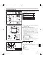
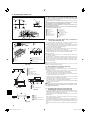
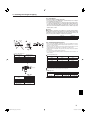
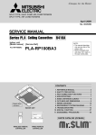
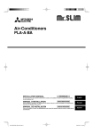
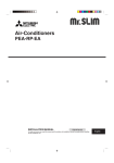
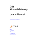
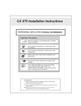
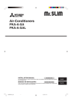
Air-Conditioners PLA-RP·BA INSTALLATION MANUAL FOR INSTALLER For safe and correct use, read this manual and the outdoor unit installation manual thoroughly before installing the air-conditioner unit. RG79D251K01_EN_0227.indd 1 English 28/02/2007 09:48:46 Contents 1. 2. 3. 4. 5. Safety precautions .....................................................................................2 Installation location ....................................................................................3 Installing the indoor unit ............................................................................3 Installing the refrigerant piping ..................................................................5 Drainage piping work.................................................................................6 6. 7. 8. 9. 10. Electrical work ...........................................................................................7 Test run....................................................................................................14 System control ........................................................................................17 Installing the grille....................................................................................17 Easy maintenance function .....................................................................19 1. Safety precautions Before installing the unit, make sure you read all the “Safety precautions”. Please report to your supply authority or obtain their consent before connecting this equipment to the power supply system. Warning: Describes precautions that must be observed to prevent danger of injury or death to the user. Caution: Describes precautions that must be observed to prevent damage to the unit. Warning: • Ask a dealer or an authorized technician to install the unit. • For installation work, follow the instructions in the Installation Manual and use tools and pipe components specifically made for use with refrigerant specified in the outdoor unit installation manual. • The unit must be installed according to the instructions in order to minimize the risk of damage from earthquakes, typhoons, or strong winds. An incorrectly installed unit may fall down and cause damage or injuries. • The unit must be securely installed on a structure that can sustain its weight. • If the air conditioner is installed in a small room, measures must be taken to prevent the refrigerant concentration in the room from exceeding the safety limit in the event of refrigerant leakage. Should the refrigerant leak and cause the concentration limit to be exceeded, hazards due to lack of oxygen in the room may result. After installation work has been completed, explain the “Safety Precautions,” use, and maintenance of the unit to the customer according to the information in the Operation Manual and perform the test run to ensure normal operation. Both the Installation Manual and Operation Manual must be given to the user for keeping. These manuals must be passed on to subsequent users. :Indicates a part which must be grounded. Warning: Carefully read the labels affixed to the main unit. • Ventilate the room if refrigerant leaks during operation. If refrigerant comes into contact with a flame, poisonous gases will be released. • All electric work must be performed by a qualified technician according to local regulations and the instructions given in this manual. • Use only specified cables for wiring. • The terminal block cover panel of the unit must be firmly attached. • Use only accessories authorized by Mitsubishi Electric and ask a dealer or an authorized technician to install them. • The user should never attempt to repair the unit or transfer it to another location. • After installation has been completed, check for refrigerant leaks. If refrigerant leaks into the room and comes into contact with the flame of a heater or portable cooking range, poisonous gases will be released. 1.1. Before installation (Environment) Caution: • Do not use the unit in an unusual environment. If the air conditioner is installed in areas exposed to steam, volatile oil (including machine oil), or sulfuric gas, areas exposed to high salt content such as the seaside, the performance can be significantly reduced and the internal parts can be damaged. • Do not install the unit where combustible gases may leak, be produced, flow, or accumulate. If combustible gas accumulates around the unit, fire or explosion may result. • Do not keep food, plants, caged pets, artwork, or precision instruments in the direct airflow of the indoor unit or too close to the unit, as these items can be damaged by temperature changes or dripping water. • When the room humidity exceeds 80% or when the drainpipe is clogged, water may drip from the indoor unit. Do not install the indoor unit where such dripping can cause damage. • When installing the unit in a hospital or communications office, be prepared for noise and electronic interference. Inverters, home appliances, highfrequency medical equipment, and radio communications equipment can cause the air conditioner to malfunction or breakdown. The air conditioner may also affect medical equipment, disturbing medical care, and communications equipment, harming the screen display quality. 1.2. Before installation or relocation Caution: • Be extremely careful when transporting the units. Two or more persons are needed to handle the unit, as it weighs 20 kg or more. Do not grasp the packaging bands. Wear protective gloves as you can injure your hands on the fins or other parts. • Be sure to safely dispose of the packaging materials. Packaging materials, such as nails and other metal or wooden parts may cause stabs or other injuries. • Thermal insulation of the refrigerant pipe is necessary to prevent condensation. If the refrigerant pipe is not properly insulated, condensation will be formed. • Place thermal insulation on the pipes to prevent condensation. If the drainpipe is installed incorrectly, water leakage and damage to the ceiling, floor, furniture, or other possessions may result. • Do not clean the air conditioner unit with water. Electric shock may result. • Tighten all flare nuts to specification using a torque wrench. If tightened too much, the flare nut can break after an extended period. 1.3. Before electric work Caution: • Be sure to install circuit breakers. If not installed, electric shock may result. • For the power lines, use standard cables of sufficient capacity. Otherwise, a short circuit, overheating, or fire may result. • When installing the power lines, do not apply tension to the cables. • Be sure to ground the unit. If the unit is not properly grounded, electric shock may result. • Use circuit breakers (ground fault interrupter, isolating switch (+B fuse), and molded case circuit breaker) with the specified capacity. If the circuit breaker capacity is larger than the specified capacity, breakdown or fire may result. 1.4. Before starting the test run Caution: • Turn on the main power switch more than 12 hours before starting operation. Starting operation just after turning on the power switch can severely damage the internal parts. • Before starting operation, check that all panels, guards and other protective parts are correctly installed. Rotating, hot, or high voltage parts can cause injuries. • Do not operate the air conditioner without the air filter set in place. If the air filter is not installed, dust may accumulate and breakdown may result. • Do not touch any switch with wet hands. Electric shock may result. • Do not touch the refrigerant pipes with bare hands during operation. • After stopping operation, be sure to wait at least five minutes before turning off the main power switch. Otherwise, water leakage or breakdown may result. 2 RG79D251K01_EN_0227.indd 2 28/02/2007 09:48:47 2. Installation location Refer to the outdoor unit installation manual. 3. Installing the indoor unit 3.1. Check the indoor unit accessories (Fig. 3-1) The indoor unit should be supplied with the following accessories. 1 2 3 4 5 6 7 8 Accessory name Installation template Washers (with insulation) Washers (without insulation) Pipe cover (for refrigerant piping joint) Small diameter Large diameter Band Screw with washer (M5 × 25) for mounting grille Drain socket Insulation Flare nut 1/4F(P60) Q'ty 1 4 4 1 1 8 4 1 1 1 Fig. 3-1 950 860-910 810 3.2. Ceiling openings and suspension bolt installation locations (Fig. 3-2) 20-45 20-45 20-45 Caution: Install the indoor unit at least 2.5m above floor or grade level. For appliances not accessible to the general public. 950 -5 20-45 160 * 50-70 *105 17 Outer side of main unit Bolt pitch Ceiling opening Outer side of Grille 17 35 +5 0 Min. 2500 135 +5 0 C D 160 840 • Using the installation template (top of the package) and the gauge (supplied as an accessory with the grille), make an opening in the ceiling so that the main unit can be installed as shown in the diagram. (The method for using the template and the gauge is shown.) * Before using, check the dimensions of template and gauge, because they change due to fluctuations of temperature and humidity. * The dimensions of ceiling opening can be regulated within the range shown in Fig.3-2; so center the main unit against the opening of ceiling, ensuring that the respective opposite sides on all sides of the clearance between them becomes identical. • Use M10 (3/8") suspension bolts. * Suspension bolts are to be procured at the field. • Install securely, ensuring that there is no clearance between the ceiling panel & grille, and between the main unit & grille. (7.5) 150 90 187.5 620 860-910 605 +35 840 160 (7.5) 160 Grille Ceiling Multi function casement (option) Entire periphery *Note that the space between ceiling panel of the unit and ceiling slab, etc. must be 10 to 15 mm. Min. 500 * When the optional multi-functional casement is installed, add 135 mm to the dimensions marked on the figure. (mm) Fig. 3-2 D 258 298 The figure marked with * in the drawing represent the dimensions of the main unit excluding those of the optional multi function casement. (Fig. 3-3) 284 377 * 190 * 170 * 140 60 C 241 281 3.3. Refrigerant and drainage piping locations of indoor unit 24 B 90 A Models 35, 50, 60, 71 100, 125, 140 (mm) Models 35, 50, 60, 71 100, 125, 140 A 80 85 B 74 77 Drain pipe Ceiling Grille Refrigerant pipe (liquid) Refrigerant pipe (gas) Water supply inlet Main unit * When the optional multi-functional casement is installed, add 135 mm to the dimensions marked on the figure. Fig. 3-3 3 RG79D251K01_EN_0227.indd 3 28/02/2007 09:48:48 3. Installing the indoor unit 3.4. Branch duct hole and fresh air intake hole (Fig. 3-4) *158 120 120 100 90 130 100 100 90 *167 70° *155 At the time of installation, use the duct holes (cut out) located at the positions shown in Fig3-4, as and when required. • A fresh air intake hole for the optional multi function casement can also be made. Note: The figure marked with * in the drawing represent the dimensions of the main unit excluding those of the optional multi function casement. When installing the optional multi function casement, add 135 mm to the dimensions marked on the figure. When installing the branch ducts, be sure to insulate adequately. Otherwise condensation and dripping may occur. Branch duct hole Indoor unit Fresh air intake hole Drain pipe Refrigerant pipe Branch duct hole diagram (view from either side) 14-ø2.8 burring hole ø150 cut out hole ø175 burring hole pitch Fresh air intake hole diagram 3-ø2.8 burring hole ø125 burring hole pitch ø100 cut out hole Ceiling 350 3.5. Suspension structure (Give site of suspension strong structure) (Fig. 3-5) Fig. 3-4 Unit Grille Pillar 605 0 81 Ceiling Rafter Beam Roof beam Use inserts rated at 100-150 kg each (procure locally) Suspension bolts M10 (3/8") (procure locally) Steel reinforcing rod Fig. 3-5 • The ceiling work differs according to the construction of the building. Building constructors and interior decorators should be consulted for details. (1) Extent of ceiling removal: The ceiling must be kept completely horizontal and the ceiling foundation (framework: wooden slats and slat holders) must be reinforced in order to protect the ceiling from vibration. (2) Cut and remove the ceiling foundation. (3) Reinforce the ends of the ceiling foundation where it has been cut and add ceiling foundation for securing the ends of the ceiling board. (4) When installing the indoor unit on a slanted ceiling, attach a pillar between the ceiling and the grille and set so that the unit is installed horizontally. Wooden structures • Use tie beams (single storied houses) or second floor beams (two story houses) as reinforcing members. • Wooden beams for suspending air conditioners must be sturdy and their sides must be at least 6 cm long if the beams are separated by not more than 90 cm and their sides must be at least 9 cm long if the beams are separated by as much as 180 cm. The size of the suspension bolts should be ø10 (3/8"). (The bolts do not come with the unit.) Ferro-concrete structures Secure the suspension bolts using the method shown, or use steel or wooden hangers, etc. to install the suspension bolts. 3.6. Unit suspension procedures (Fig. 3-6) 17 +5 0 A=17 +50 105 (240) Min. 30 Suspension bolt Ceiling Nut Washer (with insulation) Mounting plate Washer (without insulation) Check using the Installation gauge Main unit Ceiling Gauge Ceiling opening dimensions Fig. 3-6 Fig. 3-7 Main unit Ceiling Installation template (top of the package) Screw with washer (Accessory) Fig. 3-8 Suspend the main unit as shown in the diagram. Figures given in parentheses represent the dimensions in case of installing optional multi function casement. 1. In advance, set the parts onto the suspension bolts in the order of the washers (with insulation), washers (without insulation) and nuts (double). • Fit the washer with cushion so that the insulation faces downward. • In case of using upper washers to suspend the main unit, the lower washers (with insulation) and nuts (double) are to be set later. 2. Lift the unit to the proper height of the suspension bolts to insert the mounting plate between washers and then fasten it securely. 3. When the main unit can not be aligned against the mounting hole on the ceiling, it is adjustable owing to a slot provided on the mounting plate. • Make sure that A is performed within 17-22 mm. Damage could result by failing to adhere to this range. (Fig. 3-7) Caution: Use the top half of the box as a protective cover to prevent dust or debris from getting inside the unit prior to installation of the decorative cover or when applying ceiling materials. 3.7. Confirming the position of main unit and tightening the suspension bolts (Fig. 3-8) • Using the gauge attached to the grille, ensure that the bottom of the main unit is properly aligned with the opening of the ceiling. Be sure to confirm this, otherwise condensation may form and drip due to air leakage, etc. • Confirm that the main unit is horizontally levelled, using a level or a vinyl tube filled with water. • After checking the position of the main unit, tighten the nuts of the suspension bolts securely to fasten the main unit. • The installation template (top of the package) can be used as a protective sheet to prevent dust from entering the main unit when the grilles are left unattached for a while or when the ceiling materials are to be lined after installation of the unit is finished. * As for the details of fitting, refer to the instructions given on the Installation template. 4 RG79D251K01_EN_0227.indd 4 28/02/2007 09:48:48 4. Installing the refrigerant piping 4.1. Precautions For devices that use R410A refrigerant • Use ester oil, ether oil or alkylbenzene oil (small amount) as the refrigeration oil applied to the flared sections. • Use C1220 copper phosphorus for copper and copper alloy seamless pipes, to connect the refrigerant pipes. Use refrigerant pipes with the thicknesses specified in the table below. Make sure the insides of the pipes are clean and do not contain any harmful contaminants such as sulfuric compounds, oxidants, debris, or dust. Warning: When installing or moving the air conditioner, use only the specified refrigerant (R410A) to charge the refrigerant lines. Do not mix it with any other refrigerant and do not allow air to remain in the lines. Air enclosed in the lines can cause pressure peaks resulting in a rupture and other hazards. Liquid pipe Gas pipe 4.2. Connecting pipes (Fig. 4-1) A 0.5 RP60-140 ø9.52 thickness 0.8 mm ø15.88 thickness 1.0 mm • Do not use pipes thinner than those specified above. 45 2 .8 R0 .4~ R0 90 RP35, 50 ø6.35 thickness 0.8 mm ø12.7 thickness 0.8 mm Fig. 4-1 • When commercially available copper pipes are used, wrap liquid and gas pipes with commercially available insulation materials (heat-resistant to 100 °C or more, thickness of 12 mm or more). • The indoor parts of the drain pipe should be wrapped with polyethylene foam insulation materials (specific gravity of 0.03, thickness of 9 mm or more). • Apply thin layer of refrigerant oil to pipe and joint seating surface before tightening flare nut. • Use two wrenches to tighten piping connections. • Use refrigerant piping insulation provided to insulate indoor unit connections. Insulate carefully. Flare cutting dimensions Copper pipe O.D. (mm) 6.35 9.52 12.7 15.88 19.05 Flare dimensions A dimensions (mm) 8.7 - 9.1 12.8 - 13.2 16.2 - 16.6 19.3 - 19.7 23.6 - 24.0 B Die Copper pipe Flare nut tightening torque Copper pipe O.D. (mm) ø6.35 ø6.35 ø9.52 ø12.7 ø12.7 ø15.88 ø15.88 ø19.05 Flare nut O.D. (mm) 17 22 22 26 29 29 36 36 Tightening torque (mm) 14-18 34-42 34-42 49-61 68-82 68-82 100-120 100-120 Apply refrigerating machine oil over the entire flare seat surface. Use correct flare nuts meeting the pipe size of the outdoor unit. Available pipe size Fig. 4-2 Copper pipe O.D. (mm) 6.35 (1/4") 9.52 (3/8") 12.7 (1/2") 15.88 (5/8") 19.05 (3/4") B (mm) Flare tool for R410A Clutch type 1.0 - 1.5 1.0 - 1.5 1.0 - 1.5 1.0 - 1.5 1.0 - 1.5 Liquid side Gas side RP35, 50 ø6.35 — ø12.7 RP60 ø6.35 ø9.52 ø15.88 RP71-140 — ø9.52 ø15.88 : Factory flare nut attachment to the heat exchanger. 5 RG79D251K01_EN_0227.indd 5 28/02/2007 09:48:49 4. Installing the refrigerant piping 4.3. Indoor unit (Fig. 4-3) Refrigerant pipe and insulating material Pipe cover (large) Pipe cover (small) Refrigerant pipe (gas) Refrigerant pipe (liquid) Band Cross-sectional view of connection Pipe Insulating material Squeeze Heat insulation for refrigerant pipes: 1 Wrap the enclosed large-sized pipe cover around the gas pipe, making sure that the end of the pipe cover touches the side of the unit. 2 Wrap the enclosed small-sized pipe cover around the liquid pipe, making sure that the end of the pipe cover touches the side of the unit. 3 Secure both ends of each pipe cover with the enclosed bands. (Attach the bands 20 mm from the ends of the pipe cover.) • After connecting the refrigerant piping to the indoor unit, be sure to test the pipe connections for gas leakage with nitrogen gas. (Check that there is no refrigerant leakage from the refrigerant piping to the indoor unit.) 4.4. For twin/triple combination Refer to the outdoor unit installation manual. , Fig. 4-3 5. Drainage piping work 5.1. Drainage piping work (Fig. 5-1) Max. 20m 1.5-2m Max. 15cm • Use VP25 (O.D. ø32 PVC TUBE) for drain piping and provide 1/100 or more downward slope. • Be sure to connect the piping joints using a polyvinyl type adhesive. • Observe the figure for piping work. • Use the included drain hose to change the extraction direction. Correct piping Support metal Wrong piping Air bleeder Insulation (9 mm or more) Raised Downward slope (1/100 or more) Odor trap Grouped piping O.D. ø32 PVC TUBE Downward slope (1/100 or more) Make it as large as possible O.D. ø38 PVC TUBE for grouped piping. (9 mm or more insulation) Indoor unit Make the piping size large for grouped piping. Up to 85 cm Fig. 5-1 (mm) 11 25 25 25 1.Connect the drain socket (supplied with the unit) to the drain port. (Fig. 5-2) (Fix the tube using PVC adhesive then secure it with a band.) 2.Install a locally purchased drain pipe (PVC pipe, O.D. ø32). (Fix the pipe using PVC adhesive then secure it with a band.) 3.Insulate the tube and pipe. (PVC pipe, O.D. ø32 and socket) 4.Check that drain flows smoothly. 5.Insulate the drain port with insulating material, then secure the material with a band. (Both insulating material and band are supplied with the unit.) Unit Fig. 5-2 Drain pipe (O.D. ø32 PVC TUBE) Insulating material Insulating material (purchased locally) Band Transparent PVC pipe Drain port (transparent) O.D. ø32 PVC TUBE (Slope 1/100 or more) Insertion margin Drain socket Matching 6 RG79D251K01_EN_0227.indd 6 28/02/2007 09:48:50 6. Electrical work 6.1. Indoor unit (Fig. 6-1) 1. Remove the electrical wiring service panel. 2. Remove the electrical box cover. 3. Wire the power cable and control cable separately through the respective wiring entries given in the diagram. • Do not allow slackening of the terminal screws. • Leave excess cable so that the electrical box cover can be suspended below the unit during servicing. (Approx. 50 to 100 mm) Entry for control cable Entry for power Clamp Electrical box cover Service panel for electrical wiring Temporary hook for electrical box cover Indoor / Outdoor unit connecting terminals Remote controller connector Secure with the clamp Earth terminal Fig. 6-1 6.1.1. Indoor unit power supplied from outdoor unit The following connection patterns are available. The outdoor unit power supply patterns vary on models.1 System 1:1 System D A B C G A B C D E F G L N S1 S1 S2 S2 S3 S3 E 1 2 F Outdoor unit power supply Earth leakage breaker Wiring circuit breaker or isolating switch Outdoor unit Indoor unit/outdoor unit connecting cords Remote controller Indoor unit * Affix label A that is included with the manuals near each wiring diagram for the indoor and outdoor units. Simultaneous twin/triple/four system G G G G S1 S1 S1 S1 S1 S2 S2 S2 S2 S2 S3 S3 S3 S3 S3 1 2 1 2 1 2 1 2 D A B C L N E F A B C D E F G Outdoor unit power supply Earth leakage breaker Wiring circuit breaker or isolating switch Outdoor unit Indoor unit/outdoor unit connecting cords Remote controller Indoor unit * Affix label A that is included with the manuals near each wiring diagram for the indoor and outdoor units. Circuit rating Wiring Wire No. × size (mm2) Indoor unit model Indoor unit-Outdoor unit *1 PLA 3× 1.5 (polar) Indoor unit-Outdoor unit earth *1 1 × Min.1.5 Remote controller-Indoor unit *2 2 × 0.3 (Non-polar) Indoor unit (Heater) L-N *3 - Indoor unit-Outdoor unit S1-S2 *3 AC 230 V Indoor unit-Outdoor unit S2-S3 *3 DC24 V Remote controller-Indoor unit *3 DC12 V *1. <For 35-140 outdoor unit application> Max. 45 m If 2.5 mm2 used, Max. 50 m If 2.5 mm2 used and S3 separated, Max. 80 m <For 200/250 outdoor unit application> Max. 18 m If 2.5 mm2 used, Max. 30 m If 4 mm2 used and S3 separated, Max. 50 m If 6 mm2 used and S3 separated, Max. 80 m *2. The 10 m wire is attached in the remote controller accessory. Max. 500 m *3. The figures are NOT always against the ground. S3 terminal has DC 24 V against S2 terminal. However between S3 and S1, these terminals are not electrically insulated by the transformer or other device. Notes: 1. Wiring size must comply with the applicable local and national code. 2. Power supply cords and indoor unit/outdoor unit connecting cords shall not be lighter than polychloroprene sheathed flexible cord. (Design 60245 IEC 57) 3. Install an earth longer than other cables. 7 RG79D251K01_EN_0227.indd 7 28/02/2007 09:48:50 6. Electrical work 6.1.2. Separate indoor unit/outdoor unit power supplies (For PUHZ application only) The following connection patterns are available. The outdoor unit power supply patterns vary on models. 1:1 1:1 System System * The indoor power supply terminal kit is required. A B C A B C D E F G H J G D L N J S1 S2 S3 B L N C H S1 S2 S3 E 1 2 F Outdoor unit power supply Earth leakage breaker Wiring circuit breaker or isolating switch Outdoor unit Indoor unit/outdoor unit connecting cords Remote controller Indoor unit Option Indoor unit power supply * Affix label B that is included with the manuals near each wiring diagram for the indoor and outdoor units. Simultaneous twin/triple/four system A B C D E F G H J * The indoor power supply terminal kits are required. A B C D G G G G L N L N L N L N L N S1 S2 S3 S1 S2 S3 S1 S2 S3 S1 S2 S3 1 2 1 2 1 2 1 2 J B C S1 S2 S3 E F H Outdoor unit power supply Earth leakage breaker Wiring circuit breaker or isolating switch Outdoor unit Indoor unit/outdoor unit connecting cords Remote controller Indoor unit Option Indoor unit power supply * Affix label B that is included with the manuals near each wiring diagram for the indoor and outdoor units. If the indoor and outdoor units have separate power supplies, refer to the table below. If the indoor power supply terminal kit is used, change the indoor unit electrical box wiring refering to the figure in the right and the DIP switch settings of the outdoor unit control board. Option L N S1 S2 S3 3 1 2 BLACK CN01 Indoor unit control board Indoor unit power supplied from outdoor unit (initial setting) (SW8) If the indoor and outdoor units have separate power supplies, change the connections of the connectors as shown in the following figure. Option Connectors L N * There are three types of labels (labels A, B and C). Affix the appropriate labels to the units according to the wiring method. S1 S2 S3 CN01 Set the SW8-3 to ON. BLUE YELLOW YELLOW BLUE ON OFF CN01 Required BLUE YELLOW BLUE YELLOW Indoor power supply terminal kit (option) Indoor unit electrical box connector connection change Label affixed near each wiring diagram for the indoor and outdoor units Outdoor unit DIP switch settings (when using separate indoor unit/outdoor unit power supplies only) Indoor unit specifications Required Required Connectors (connections of initial setting are for indoor unit power supplied from outdoor unit) BLACK CN01 Indoor unit control board Separate indoor unit/outdoor unit power supplies Circuit rating Wiring Wire No. × size (mm2) Indoor unit model Indoor unit power supply Indoor unit input capacity Main switch (Breaker) Indoor unit power supply Indoor unit power supply earth Indoor unit-Outdoor unit Indoor unit-Outdoor unit earth Remote controller-Indoor unit Indoor unit L-N Indoor unit-Outdoor unit S1-S2 Indoor unit-Outdoor unit S2-S3 Remote controller-Indoor unit *1 *2 *3 *4 *4 *4 *4 PLA ~/N (single), 50 Hz, 230 V 16 A 2 × Min. 1.5 1 × Min. 1.5 2 × Min. 0.3 – 2 × 0.3 (Non-polar) AC 230 V – DC24 V DC12 V *1. A breaker with at least 3.0 mm contact separation in each pole shall be provided. Use non-fuse breaker (NF) or earth leakage breaker (NV). The breaker shall be provided to ensure disconnection of all active phase conductors of the supply. *2. Max. 120 m *3. The 10 m wire is attached in the remote controller accessory. Max. 500 m *4. The figures are NOT always against the ground. Notes: 1. Wiring size must comply with the applicable local and national code. 2. Power supply cords and indoor unit/outdoor unit connecting cords shall not be lighter than polychloroprene sheathed flexible cord. (Design 60245 IEC 57) 3. Install an earth longer than other cables. 8 RG79D251K01_EN_0227.indd 8 28/02/2007 09:48:51 6. Electrical work 6.2. Remote controller 6.2.1. For wired remote controller 30 1) Installing procedures (1) Select an installing position for the remote controller. (Fig. 6-2) The temperature sensors are located on both remote controller and indoor unit. Procure the following parts locally: Two piece switch box Thin copper conduit tube Lock nuts and bushings [Fig.6-2] 30 30 83.5 46 Remote controller profile 120 Required clearances surrounding the remote controller Installation pitch (2) Seal the service entrance for the remote controller cord with putty to prevent possible invasion of dew drops, water, cockroaches or worms. (Fig. 6-3) For installation in the switch box For direct installation on the wall, select one of the following: • Prepare a hole through the wall to pass the remote controller cord (in order to run the remote controller cord from the back), then seal the hole with putty. • Run the remote controller cord through the cut-out upper case, then seal the cutout notch with putty. B-1. To lead the remote controller cord from the back of the controller B-2. To run the remote controller cord through the upper portion [Fig.6-3] Fig. 6-2 B-1. B-2. Wall Conduit Lock nut Bushing Fig. 6-3 Switch box Remote controller cord Seal with putty Wood screw 2) Connecting procedures (Fig. 6-4) Connect the remote controller cord to the terminal block. To TB5 on the indoor unit TB6 (No polarity) AB 3) Two remote controllers setting If two remote controllers are connected, set one to “Main” and the other to “Sub”. For setting procedures, refer to “Function selection of remote controller” in the operation manual for the indoor unit. TB6 Fig. 6-4 6.2.2. For wireless remote controller 1) Installation area • Area in which the remote controller is not exposed to direct sunshine. • Area in which there is no nearby heating source. • Area in which the remote controller is not exposed to cold (or hot) winds. • Area in which the remote controller can be operated easily. • Area in which the remote controller is beyond the reach of children. 2) Installation method (Fig. 6-5) Attach the remote controller holder to the desired location using two tapping screws. Place the lower end of the controller into the holder. MODEL SELECT ON/OFF MODE TEMP FAN AUTO STOP VANE AUTO START CHECK LOUVER SET Fig. 6-5 h min TEST RUN RESET CLOCK Fig. 6-6 Remote controller Indoor PLA MODEL SELECT ON/OFF MODE TEMP FAN AUTO STOP VANE AUTO START CHECK LOUVER SET h min TEST RUN RESET CLOCK Wall Display panel Receiver • The signal can travel up to approximately 7 meters (in a straight line) within 45 degrees to both right and left of the center line of the receiver. 3) Setting (Fig. 6-6) Insert batteries. Press the SET button with something sharp at the end. MODEL SELECT blinks and Model No. is lighted. Press the temp buttons to set the Model No. button and operate again If you mistook the operation, press the ON/OFF from procedure . Press the SET button with something sharp at the end. MODEL SELECT and Model No. are lighted for three seconds, then turned off. Outdoor PUH, PUHZ, SUZ PU Model No. 001 033 4)Automatic fan speed setting (For wireless remote controller) It is necessary to set for wireless remote controller only when automatic fan speed is not set at default setting. It is not necessary to set for wired remote controller with automatic fan speed at default setting. 1. Press the SET button with something sharp at the end. Operate when display of remote controller is off. MODEL SELECT blinks and Model No. is lighted . 2. Press the AUTO STOP button. blinks and setting No. is lighted . (Setting No.01: without automatic fan speed ) buttons to set the setting No.02. 3. Press the temp. (Setting No.02:with automatic fan speed ) If you mistook the operation, press the ON/OFF button and operate again from procedure 2. 4. Press the SET button with something sharp at the end. MODEL SELECT and Model No. are lighted for 3 seconds, then turned off. Fig. 6-7 9 RG79D251K01_EN_0227.indd 9 28/02/2007 09:48:52 6. Electrical work 5) Assigning a remote controller to each unit (Fig. 6-8) Each unit can be operated only by the assigned remote controller. Make sure each pair of an indoor unit PC board and a remote controller is assigned to the same pair No. 6) Wireless remote controller pair number setting operation Press the SET button with something sharp at the end. Start this operation from the status of remote controller display turned off. MODEL SELECT blinks and Model No. is lighted. min button twice continuously. Press the Pair No. “0” blinks. Press the temp buttons to set the pair number you want to set. button and operate again If you mistook the operation, press the ON/OFF from procedure 2. Press the SET button with something sharp at the end. Set pair number is lighted for three seconds then turned off. MODEL SELECT ON/OFF MODE TEMP FAN AUTO STOP VANE AUTO START CHECK LOUVER TEST RUN SET h min RESET CLOCK Fig. 6-8 A Pair No. of wireless remote controller Indoor PC board 0 Factory setting 1 Cut J41 2 Cut J42 3-9 Cut J41, J42 6.3. Function settings Mode number Setting number Refrigerant address Unit number TEMP. MENU BACK MONITOR/SET PAR-21MAA ON/OFF ON/OFF FILTER DAY CLOCK CHECK TEST OPERATION CLEAR Fig. 6-9 CHECK CHECK CHECK CHECK CHECK ON/OFF MODE TEMP FAN AUTO STOP VANE AUTO START CHECK LOUVER TEST RUN SET h min RESET CLOCK Fig. 6-10 6.3.1. Function setting on the unit (Selecting the unit functions) 1) For wired remote controller (Fig. 6-9) Changing the power voltage setting • Be sure to change the power voltage setting depending on the voltage used. Go to the function setting mode. Switch OFF the remote controller. and TEST RUN buttons simultaneously and Press the FILTER hold them for at least 2 seconds. FUNCTION will start to blink. Use the buttons to set the refrigerant address (3) to 00. Press button and [--] will start to blink in the unit number (4) display. Use the buttons to set the unit number (4) to 00. Press the MODE button to designate the refrigerant address/unit number. [--] will blink in the mode number (1) display momentarily. Press the buttons to set the mode number (1) to 04. Press the button and the current set setting number (2) will blink. Use the button to switch the setting number in response to the power supply voltage to be used. Power supply voltage 240 V : setting number = 1 220 V, 230 V : setting number = 2 Press the MODE button and mode and the setting number (1) and (2) will change to being on constantly and the contents of the setting can be confirmed. Press the FILTER and TEST RUN buttons simultaneously for at least two seconds. The function selection screen will disappear momentarily and the air conditioner OFF display will appear. 2) For wireless remote controller (Fig. 6-10) Changing the power voltage setting • Be sure to change the power voltage setting depending on the voltage used. Going to the function select mode CHECK button twice continuously. Press the (Start this operation from the status of remote controller display turned off.) CHECK is lighted and “00” blinks. Press the temp button once to set “50”. Direct the wireless remote controller h button . toward the receiver of the indoor unit and press the Setting the unit number Press the temp buttons and to set the unit number “00”. Direct the wiremin butless remote controller toward the receiver of the indoor unit and press the ton . Selecting a mode Enter 04 to change the power voltage setting using the temp buttons and . Direct the wireless remote controller toward the receiver of the indoor unit and h button . press the Current setting number: 1 = 1 beep (one second) 2 = 2 beeps (one second each) 3 = 3 beeps (one second each) Selecting the setting number temp buttons and to change the power voltage setting to 01 (240 Use the V). Direct the wireless remote controller toward the sensor of the indoor unit and h button . press the To select multiple functions continuously and to change multiple function settings continuously. Repeat steps Complete function selection Direct the wireless remote controller toward the sensor of the indoor unit and press button . the Note: Whenever changes are made to the function settings after installation or maintenance, be sure to record the changes with a mark in the “Setting” column of the Function table. 6.3.2. Function setting on the remote controller Refer to the indoor unit operation manual. 10 RG79D251K01_EN_0227.indd 10 28/02/2007 09:48:54 6. Electrical work Function table Select unit number 00 Mode Power failure automatic recovery Settings Not available Available *1 Indoor unit operating average Set by indoor unit’s remote controller Remote controller’s internal sensor Not Supported Supported (indoor unit is not equipped with outdoor-air intake) Supported (indoor unit is equipped with outdoor-air intake) 240 V 220 V, 230 V Indoor temperature detecting LOSSNAY connectivity Power voltage Mode no. 01 02 03 04 Setting no. Initial setting 1 2 1 2 3 1 2 3 1 2 setting Select unit numbers 01 to 03 or all units (AL [wired remote controller]/07 [wireless remote controller]) Settings 100Hr 2500Hr No filter sign indicator Silent Standard High ceiling 4 directions 3 directions 2 directions Not supported Supported Equipped with vanes (vanes angle setup 3) Equipped with vanes (vanes angle setup 1) Equipped with vanes (vanes angle setup 2) Mode Filter sign Fan speed No. of air outlets Installed options (high-performance filter) Up/down vane setting Mode no. 07 08 09 10 11 Setting no. Initial setting 1 2 3 1 2 3 1 2 3 1 2 1 2 3 setting *1 When the power supply returns, the air conditioner will start 3 minutes later. *2 Power failure automatic recovery initial setting depends on the connecting outdoor unit. 6.3.3 How to set the fixed up/down air direction (Only for wired remote controller and PUHZ-RP/P, PU(H)-P application) Horizontal airflow • Only the particular outlet can be fixed to certain direction with the procedures below. Once fixed, only the set outlet is fixed every time air conditioner is turned on. (Other outlets follow UP/DOWN air direction setting of the remote controller.) Explanation of word • "Refrigerant address No." and "Unit No." are the numbers given to each air conditioner. • "Outlet No." is the number given to each outlet of air conditioner. (Refer to the right.) • "Up/Down air direction" is the direction (angle) to fix. Downward Remote controller setting Fixed setting The airflow direction of this outlet is controlled by the airflow direction setting of remote contoller. The airflow direction of this outlet is fixed in particular direction. When it is cold because of direct airflow, the airflow direction can be fixed horizontally to avoid direct airflow. Outlet No.3 Outlet No.4 MITSUBISHI ELECTRIC label Reset 1 horizontal 2 3 4 5 Outlet No.2 Outlet No.1 Note: "0" indicates all outlets. 11 RG79D251K01_EN_0227.indd 11 28/02/2007 09:48:56 6. Electrical work Operation buttons (During the fixed airflow direction mode) Press the button with either refrigerant address No., unit No. or outlet No. blinking, ... ON/OFF button Resets the fixed airflow direction mode. Fan Speed button TEMP. MENU BACK MONITOR/SET PAR-21MAA ON/OFF ON/OFF Filter button (<Enter> button) FILTER DAY CHECK TEST OPERATION CLOCK Press for 2 seconds to change / cancel "Fixed airflow direction mode". Only the air conditioner with the No. on remote controller and its outlet are set to the setting 5 of the airflow direction. (Other outlets are closed.) It is used to identify the air conditioner and outlet to set. Sends the information on remote controller display. CLEAR Press the button with Up/Down air direction indicater blinking, ... Check button (Clear button) ·Refer to the next page for details. Attention Mode button (Return button) Moves between the selected(blinking) parts. Unit No. Outlet No. Refrigerant addres No. Up/Down air direction Set temperature buttons Down Only the air conditioner with the No. on Remote controller and its outlet are fixed at "Up/Down air direction" which is blinking. This is used only to decide direction conclusively. Attention: Be careful not to set wrong air conditioner. Up Changes the selection(No.). Unit No. "1-4" Outlet No. Up/Down air direction Refrigerant address No. "00-15" 5 steps or "1-4"or "0" cancel 2.Press Filter < Process for setting > [1] To turn off air conditioner and change the remote controller to "Fixed airflow direction mode" 1.Press ON/OFF button to turn off the air conditioner. 2.Press Fan Speed button and Filter button for more than 2 seconds simultaneously and it becomes the fixed airflow direction mode after a while. "Fixed airflow direction mode" display button to send the information on remote controller. 3. Wait for 15 seconds . How does the air conditioner run? Only the air from the selected outlet blows downward. Go to step[3]. Air from the wrong outlet blows downward. Repeat 1 and set again. All outlets are closed. The numbers of the air conditioner (refrigerant address No., Unit No.) are wrong. Refer to How to find air conditioner No.. [3] To fix air direction Air blows downward after it becomes "fixed airflow direction mode" [2] To select and identify the outlet to set 1.Press Set Temperature button to change number with the outlet No. blinking. Select outlet No. to set. Unit No. Outlet No. Outlet No.3 Up/Down air direction Refrigerant addres No. Outlet No.4 MITSUBISHI ELECTRIC label Outlet No.2 1.Press Mode button (Return button) to blink Up/Down air direction indicater. 2.Press Set Temperature button until the direction to set is chosen. 3.Press Filter button to send the information on remote controller to air conditioner. 4.Wait for 15 seconds . How does the air conditioner run? Airflow direction is set in the selected direction. The fixed setting completed (Go to step [4].) Airflow direction is set in the wrong direction. Repeat 2. and set again. Outlet No.1 Note: "0" indicates all outlets. Unit No. Outlet No. Up/Down air direction Refrigerant addres No. Air direction changes This indicates NO FIXED SETTING(canceled) [4] To cancel "Fixed airflow direction mode" 1.Press ON/OFF button to cancel "Fixed airflow direction mode". It is also canceled by pressing Fan Speed button and Filter button for more than 2 seconds simultaneously. 2.Do not operate remote controller for 30 seconds after the "Fixed airflow direction mode" is canceled. It does not accept even if it is operated. 12 RG79D251K01_EN_0227.indd 12 28/02/2007 09:48:57 6. Electrical work How to find air conditioner No. Each air conditioner has its own refrigerant address No. and unit No. (Example below). To find air conditioner No. to set, refer to the procedures below. Air conditioner No. is found by its airflow direction with the unit No. changed one after the other. Flow of procedure Refrigerant address No."00" Unit No."1" Refrigerant address No."01" Unit No."2" Unit No."1" Unit No."2" Adjust to the next unit No.with Set Temperature button . (refrigerant address No.00 is remained.) button to send the information on remote controller. 2. Press Filter 3. Wait for 15 seconds . How does the air conditioner run? Only air from the outlet which No. displayed on remote controller blows downward. No. displayed on remote controller is air conditioner No.. (Checking completed) All outlets are closed. Repeat [1] and check. (If all the numbers are checked up to No.4 and is not found, go to [3].) "Err" is displayed on remote controller. The refrigerant address does not have further unit No.. (Go to [3].) Remote controller As for this air conditioner, air conditioner No. is "unit No. 1" of refrigerant address "0". Err Check from refrigerant address 00 at first. Change to unit No.1 and check Change to unit No.1 and check Change to unit No.2 and check Change to unit No.2 and check Change to unit No.3 and check Change to unit No.3 and check Change to unit No.4 and check Change to unit No.4 and check Change to unit No.1 and check Change to unit No.1 and check Change to unit No.2 and check Change to unit No.2 and check Change to unit No.3 and check Change to unit No.3 and check Change to unit No.4 and check Change to unit No.4 and check [3] To check Unit No. of following refrigerant address No.(Maxmum refrigerant address No. is 15) 1.Press Mode button (Return button) to blink refrigerant address No.. Adjust refrigerant No. with Set Temperature button . * By changing refrigerant address, unit No. and outlet No. turn to initial display. 2.Go back to [2] and check Unit No. again from Unit No. 1 in order. Unit No. Outlet No. Up/Down air direction Refrigerant addres No. When "Err" is displayed, refrigerant address does not have further "unit No.". Change to the next "refrigerant address No.. (Refrigerant No "00"~max. No."15") <Process to find air conditioner No.> To clear fixed setting To clear all fixed setting(reset to factory default), press check button(clear botton) for more than 3 seconds in fixed airflow direction mode. Display of remote controller blinks and the set information is cleared. Note: This operation clears the fixed setting information of all air conditioner connected to the remote controller. [1] To check refrigerant address No. and unit No. 1.Press Mode button (Return button) and unit No. or refrigerant address No. blinks. Adjust refrigerant address No.to "00" and unit No."1" with Set Temperature button . Unit No. Outlet No. Up/Down air direction Refrigerant addres No. 2.Press Filter button to send the information on remote controller. 3. Wait for 15 seconds. How does the air conditioner run? Only air from the outlet of which No. displayed on remote controller blows downward. Refrigerant address No.00 and unit No.1 are the air conditioner No.. All outlets are closed. Go to step [2]. [2] To check by changing unit No. one after the other (Maximum unit No. is 4) 1.Press Mode button (Return button) and unit No. blinks. Unit No. Outlet No. Up/Down air direction Refrigerant addres No. 13 RG79D251K01_EN_0227.indd 13 28/02/2007 09:49:00 7. Test run 7.1. Before test run After completing installation and the wiring and piping of the indoor and outdoor units, check for refrigerant leakage, looseness in the power supply or control wiring, wrong polarity, and no disconnection of one phase in the supply. Use a 500-volt megohmmeter to check that the resistance between the power supply terminals and ground is at least 1.0 M . Do not carry out this test on the control wiring (low voltage circuit) terminals. Warning: Do not use the air conditioner if the insulation resistance is less than 1.0 M . 7.2. Test run ON/OFF button Test run display Liquid pipe (Indoor unit) temperature display ON/OFF lamp Power display Error code display Test run remaining time display TEST RUN COOL, HEAT °C °C SIMPLE TEMP. MENU BACK ON/OFF MONITOR/SET PAR-21MAA ON/OFF Set temperature button Mode selection button Air direction button TEST button Fan Speed button Louver button FILTER DAY CHECK TEST OPERATION CLOCK CLEAR Fig. 7-1 The following 3 methods are available. 7.2.1. Using wired remote controller (Fig. 7-1) Turn on the power at least 12 hours before the test run. Press the [TEST] button twice. “TEST RUN” liquid crystal display Press the [Mode selection] button and switch to the cooling (or heating) mode. Make sure that cold (or warm) wind is blown out. Press the [Fan speed] button. Make sure that the wind speed is switched. Press the [Air direction button] or [Louver button]. Check operation of the vane or louver. Check operation of the outdoor unit fan. Release test run by pressing the [ON/OFF] button. Stop Register a telephone number. The telephone number of the repair shop, sales office, etc., to contact if an error occurs can be registered in the remote controller. The telephone number will be displayed when an error occurs. For registration procedures, refer to the operation manual for the indoor unit. 7.2.2. Using wireless remote controller (Fig. 7-2) Turn on the power to the unit at least 12 hours before the test run. TEST RUN Press the button twice continuously. (Start this operation from the status of remote controller display turned off.) TEST RUN and current operation mode are displayed. TEST RUN Press the MODE button to activate mode, then check whether cool air is blown out from the unit. Press the ON/OFF TEMP , FAN VANE AUTO STOP Press the VANE AUTO START Press the ON/OFF button to stop the test run. TEST RUN button and check whether the auto vane operates properly. h Note: • Point the remote controller towards the indoor unit receiver while following steps to . • It is not possible to run the TEST RUN in FAN, DRY or AUTO mode. min RESET mode, then check whether button and check whether fan speed changes. FAN CHECK LOUVER SET button to activate warm air is blown out from the unit. Press the MODE MODE CLOCK Fig. 7-2 7.2.3. Using SW4 in outdoor unit Refer to the outdoor unit installation manual. 7.3. Self-check 7.3.1. Wired remote controller (Fig. 7-3) Turn on the power. Press the [CHECK] button twice. Set refrigerant address with [TEMP] button if system control is used. Press the [ON/OFF] button to stop the self-check. CHECK ERROR CODE TEMP. MENU BACK PAR-21MAA MONITOR/SET ON/OFF ON/OFF DAY CLOCK ON/OFF TEMP CHECK button FILTER CHECK TEST OPERATION CLEAR MODE FAN AUTO STOP VANE AUTO START Refrigerant address TEMP. button IC: Indoor unit OC: Outdoor unit Check code CHECK LOUVER TEST RUN ERROR CODE SET h Unit address min RESET CLOCK 7.3.2. Wireless remote controller (Fig. 7-4) Turn on the power. CHECK button twice. Press the (Start this operation from the status of remote controller display turned off.) begins to light. ERROR CODE Fig. 7-4 “00” begins to blink. h Fig. 7-3 While pointing the remote controller toward the unit’s receiver, press the button. The check code will be indicated by the number of times that the buzzer sounds from the receiver section and the number of blinks of the operation lamp. Press the ON/OFF button to stop the self-check. 14 RG79D251K01_EN_0227.indd 14 28/02/2007 09:49:03 7. Test run • Refer to the following tables for details on the check codes. (Wireless remote controller) [Output pattern A] Beeper sounds OPERATION INDICATOR lamp blinking pattern Beep Beep Beep Beep Beep Beep 1st 2nd 3rd nth 1st Beep 2nd · · · Repeated Off On On On Off On On On 0.5 sec. Approx. 2.5 sec. 0.5 sec. 0.5 sec. Self-check Approx. 2.5 sec. 0.5 sec. 0.5 sec. 0.5 sec. starts (Start signal Number of blinks/beeps in pattern indicates the check Number of blinks/beeps in pattern indicates received) code in the following table (i.e., n=5 for “P5”) the check code in the following table [Output pattern B] Beeper sounds OPERATION INDICATOR lamp blinking pattern Beep Off Self-check Approx. 2.5 sec. starts (Start signal received) [Output pattern A] Beep Beep Beep Beep 1st 2nd 3rd nth 1st On On On 0.5 sec. 0.5 sec. 0.5 sec. On 0.5 sec. Off Approx. 2.5 sec. On Approx. 3 sec. Number of blinks/beeps in pattern indicates the check code in the following table (i.e., n=5 for “U2”) On 0.5 sec. Beep 2nd · · · Repeated On 0.5 sec. Number of blinks/beeps in pattern indicates the check code in the following table Errors detected by indoor unit Wireless remote controller Beeper sounds/OPERATION INDICATOR lamp blinks (Number of times) 1 2 3 4 5 6 7 8 9 10 11 12 No sound No sound No sound [Output pattern B] On Approx. 3 sec. Beep Wired remote controller Symptom Remark Check code P1 P2 P9 E6, E7 P4 P5 PA P6 EE P8 E4 — — Fb E0, E3 E1, E2 ———— Intake sensor error Pipe (TH2) sensor error Pipe (TH5) sensor error Indoor/outdoor unit communication error Drain sensor error / Float switch connector open Drain pump error Forced compressor error Freezing/Overheating protection operation Communication error between indoor and outdoor units Pipe temperature error Remote controller signal receiving error — — Indoor unit control system error (memory error, etc.) Remote controller transmission error Remote controller control board error No corresponding Errors detected by unit other than indoor unit (outdoor unit, etc.) Wireless remote controller Beeper sounds/OPERATION INDICATOR lamp blinks (Number of times) 1 2 3 4 5 6 7 8 9 10 Wired remote controller Symptom Remark Indoor/outdoor unit communication error (Transmitting error) (Outdoor unit) Compressor overcurrent interruption Open/short of outdoor unit thermistors Compressor overcurrent interruption (When compressor locked) Abnormal high discharging temperature/49C worked/insufficient refrigerant Abnormal high pressure (63H worked)/Overheating protection operation Abnormal temperature of heat sink Outdoor unit fan protection stop Compressor overcurrent interruption/Abnormal of power module Abnormality of super heat due to low discharge temperature Abnormality such as overvoltage or voltage shortage and abnormal synchronous signal to main circuit/Current sensor error — — Other errors (Refer to the technical manual for the outdoor unit.) For details, check the LED display of the outdoor controller board. Check code E9 UP U3, U4 UF U2 U1, Ud U5 U8 U6 U7 11 U9, UH 12 13 14 — — Others *1 If the beeper does not sound again after the initial two beeps to confirm the self-check start signal was received and the OPERATION INDICATOR lamp does not come on, there are no error records. *2 If the beeper sounds three times continuously “beep, beep, beep (0.4 + 0.4 + 0.4 sec.)” after the initial two beeps to confirm the self-check start signal was received, the specified refrigerant address is incorrect. • On wireless remote controller The continuous buzzer sounds from receiving section of indoor unit. Blink of operation lamp • On wired remote controller Check code displayed in the LCD. 15 RG79D251K01_EN_0227.indd 15 28/02/2007 09:49:04 7. Test run • If the unit cannot be operated properly after the test run has been performed, refer to the following table to remove the cause. Symptom Wired remote controller For about 2 minutes after power-on PLEASE WAIT PLEASE WAIT Error code Display messages do not appear even when operation switch is turned ON (operation lamp does not light up). LED 1, 2 (PCB in outdoor unit After LED 1, 2 are lighted, LED 2 is turned off, then only LED 1 is lighted. (Correct operation) Only LED 1 is lighted. Subsequent to about 2 minutes after poweron LED 1, 2 blink. Only LED 1 is lighted. LED 1 blinks twice, LED 2 blinks once. Cause •For about 2 minutes after power-on, operation of the remote controller is not possible due to system start-up. (Correct operation) •Connector for the outdoor unit’s protection device is not connected. Reverse or open phase wiring for the outdoor unit’s power terminal block (L1, L2, L3) • Incorrect wiring between indoor and outdoor units (incorrect polarity of S1, S2, S3) •Remote controller wire short On the wireless remote controller with condition above, following phenomena take place. • No signals from the remote controller are accepted. • Operation lamp is blinking. • The buzzer makes a short ping sound. Note: Operation is not possible for about 30 seconds after cancellation of function selection. (Correct operation) For description of each LED (LED1, 2, 3) provided on the indoor controller, refer to the following table. LED 1 (power for microcomputer) LED 2 (power for remote controller) LED 3 (communication between indoor and outdoor units) Indicates whether control power is supplied. Make sure that this LED is always lit. Indicates whether power is supplied to the remote controller. This LED lights only in the case of the indoor unit which is connected to the outdoor unit refrigerant address “0”. Indicates state of communication between the indoor and outdoor units. Make sure that this LED is always blinking. Water supply pump Water (about 1000cc) Drain plug Pour water through outlet .Be carefule not to spray water into the drain pump mechanism. 7.4. Check of drainage (Fig. 7-5) • Ensure that the water is being properly drained out and that no water is leaking from joints. When electric work is completed. . Pour water during cooling operation and check. When electric work is not completed. . Pour water during emergency operation and check. * Drain pump and fan are activated simultaneously when single phase 220-240V is turned on to S1 and S2 on terminal block after the connecter (SWE) on controller board in the electrical branch box is set to ON. Be sure to turn it back to the former state after work. 16 RG79D251K01_EN_0227.indd 16 28/02/2007 09:49:05 8. System control Refer to the outdoor unit installation manual. 9. Installing the grille 9.1. Checking the contents (Fig. 9-1) • This kit contains this manual and the following parts. 20 Accessory name Grille Screw with captive washer Gauge Fastener Screw Screw Wireless remote controller Wired remote controller Q’ty 1 4 1 3 4 1 1 1 Remarks 950 × 950 (mm) M5 × 0.8 × 25 (Divided into four parts) 4×8 4 × 12 for PLP-6BALM for PLP-6BAMD 9.2. Preparing to attach the grille (Fig. 9-2) ON/OFF • With the gauge supplied with this kit, adjust and check the positioning of the unit relative to the ceiling. If the unit is not properly positioned relative to the ceiling, it may allow air leaks or cause condensation to collect. • Make sure that the opening in the ceiling is within the following tolerances: 860 860 - 910 910 • Make sure that A is performed within 17-22 mm. Damage could result by failing to adhere to this range. ? Fig. 9-1 A=17 +50 Main unit Ceiling Gauge (inserted into the unit) Ceiling opening dimensions 9.2.1. Removing the intake grille (Fig. 9-3) • Slide the levers in the direction indicated by the arrows to open the intake grille. • Unlatch the hook that secures the grille. * Do not unlatch the hook for the intake grille. • With the intake grille in the “open” position, remove the hinge of the intake grille from the grille as indicated by the arrows . Fig. 9-2 9.2.2. Removing the corner panel (Fig. 9-4) • Remove the screw from the corner of the corner panel. Slide the corner panel as indicated by the arrow to remove the corner panel. [Fig.9-3] [Fig.9-4] Fig. 9-3 Intake grille Grille Intake grille levers Grille hook Hole for the grille’s hook Corner panel Screw Detail Fig. 9-4 4-directional 3-directional One pattern: Factory setting 4 patterns: One air outlet fully closed Blowout direction patterns 2-directional 9.3. Selection of the air outlets For this grille the discharge direction is available in 11 patterns. Also, by setting the remote controller to the appropriate settings, you can adjust the air-flow and speed. Select the required settings from the Table 1 according to the location in which you want to install the unit. 1) Decide on the discharge direction pattern. 2) Be sure to set the remote contoller to the appropriate settings according to the number of air outlets and the height of the ceiling on which the unit will be installed. Note: For 3 and 2-directional, please use the air outlet shutter plate (option). 6 patterns: Two air outlet fully closed Blowout direction patterns 9.4. Installing the grille 9.4.1. Preparations (Fig. 9-5) • Install the two enclosed screws with washer in the main unit (at the corner drain pipe area and at the opposite corner) as shown in the diagram. 15-20 Table 1 Main unit Screw with captive washer Fig. 9-5 17 RG79D251K01_EN_0227.indd 17 28/02/2007 09:49:05 9. Installing the grille 9.4.2. Temporary installation of the grille (Fig. 9-6) Main unit Corner drain pipe area Screw with washer (for temporary use) Grille Screw with washer Socket Bell shaped hole • Temporarily secure the grille using the bell shaped holes by putting the socket of on the corner drain pipe area of the main unit. the grille marked * Make sure that the lead wiring of the grille does not get pinched between the grille and the main unit. 9.4.3. Securing the grille (Fig. 9-7) • Secure the grille to the main unit by tightening the previously installed two screws (with captive washer) as well as the two remaining screws (with captive washer). * Make sure that there are no gaps between the main unit and the grille or the grille and the ceiling. Fixing gaps between the grille and the ceiling With the grille attached, adjust the height of the main unit to close the gap. 9.4.4. Wire connection (Fig. 9-8) Fig. 9-6 • Remove the 2 screws fixing the cover of electrical branch box of the unit and open the cover. • Be sure to connect the connector(white, 20-pole) for vane motor of the grille to CNV connector of contoller board of the unit. • As for PLP-6BALM, the connector of wireless sensor cable is also connected to connecor CN90 on indoor controller board. The lead wire of grille is passed through the catch of bell mouth of the unit perfectly. The remaining lead wire is tied with clamp of the unit and put the cover of the unit again with 2 screws. Ceiling Note: Do not put the remaining lead wire in electrical branch box of the unit. Main unit Grille Make sure that there are no gaps Adjust the nut of the main unit using a wrench, etc. Fig. 9-7 Clamp of the main unit Electrical box Indoor controler board Catch for bell mouth Lead wire of grille 9.5. Locking the up/down airflow direction (Fig. 9-9) The vanes of the unit can be set and locked in up or down orientations depending upon the environment of use. • Set according to the preference of the customer. The operation of the fixed up/down vanes and all automatic controls cannot be performed using the remote controller. In addition, the actual position of the vanes may differ from the position indicated on the remote controller. Turn off the main power switch. Injuries or an electrical shock may occur while the fan of the unit is rotating. Disconnect the connector for the vane motor of the vent that you want to lock. (While pressing the button, remove the connector in the direction indicated by the arrow as shown in the diagram.) After removing the connector, insulate it with tape. It also can be set by remote controller. Refer to 6.3.3. 9.6. Check • Make sure that there is no gap between the unit and the grille, or between the grille and the surface of the ceiling. If there is any gap between the unit and the grille, or between the grille and the surface of the ceiling, it may cause dew to collect. • Make sure that the wires have been securely connected. Fig. 9-8 Button Vane motor Up/down vanes Connector Fig. 9-9 18 RG79D251K01_EN_0227.indd 18 28/02/2007 09:49:07 9. Installing the grille 9.7. Installing the intake grille (Fig. 9-10 ) Note: When reinstalling the corner panels (each with a safety wire attached), connect the other end of each safety wire to the grille using a screw (4 pcs, 4 8) as shown in the illustration. *If the corner panels are not attached, they may fall off while the unit is operating. • Perform the procedure that is described in “9.2. Preparing to attach the grille” in reverse order to install the intake grille and the corner panel. • Multiple units can be installed with grille so that the position of the logo on each corner panel is consistent with the other units regardless of the orientation of the intake grille. Align the logo on the panel according to the wishes of the customer as shown in the diagram to the left. (The position of the grille can be changed.) Refrigerant piping of the main unit Drain piping of the main unit Position of the corner panel when sent from the factory (logo attached). * Installation in any position is possible. (Enlarged) Screw (4ޓ8)ޓ Corner panel Safety wire Position of the levers on the intake grille when sent from the factory. * Although the clips can be installed in any of four positions, the configuration shown here is recommended.(It is not necessary to remove the intake grille when maintenance is performed on the electric component box of the main unit.) Fig. 9-10 Receiver (Only PLP-6BALM Panel) 10. Easy maintenance function (For PUHZ-RP application only) Display example (Comp discharge temperature 64 By using the maintenance mode, you can display many types of maintenance data on the remote controller such as the heat exchanger temperature and compressor current consumption for the indoor and outdoor units. This function can be used whether the air conditioner is operating or not. During air conditioner operation, data can be checked during either normal operation or maintenance mode stable operation. * This function cannot be used during the test run. * The availability of this function depends on the connecting outdoor unit. Refer to the brochures. ) PAR-21MAA Maintenance mode operation procedures (1) Press the TEST button for three seconds to activate the maintenance mode. (2) Press the TEMP. MAINTENANCE Display buttons to set the refrigerant address. Display (3) Select the data you want to display. Cumulative operation time Compressor information MENU Outdoor unit information Display Heat exchanger temperature Display ON/OFF Indoor unit information COMP ON x10 HOURS OUTDOOR UNIT H•EXC. TEMP Indoor room temperature Display INDOOR UNIT INLET TEMP Operation current ON/OFF number COMP ON x100 TIMES COMP ON CURRENT (A) Outdoor ambient temperature Comp discharge temperature OUTDOOR UNIT OUTLET TEMP OUTDOOR UNIT OUTDOOR TEMP Filter operation time Heat exchanger temperature INDOOR UNIT H•EXC. TEMP INDOOR UNIT FILTER USE H * The filter operation time displayed is the number of hours the filter has been used since the filter reset was performed. Stable operation Using the maintenance mode, the operation frequency can be fixed and the operation can be stabilized. If the air conditioner is stopped, use the following procedure to start this operation. Press the MODE button to select the operation mode. Stable cooling operation (4) Press the FILTER button. (5) The data is displayed in Display . COOL STABLE MODE Stable heating operation HEAT STABLE MODE Stable operation cancellation STABLE MODE CANCEL (Airflow temperature display example) Blinking Press the FILTER button. Display Waiting for response Approx. 10 sec. 64 * Repeat steps (2) to (5) to check another data. Display (6) Press the TEST button for three seconds or press the deactivate the maintenance mode. Stable operation Waiting for stable operation ON/OFF button to 10-20 min. * You can check the data using steps (3) to (5) of the maintenance mode operation procedures while waiting for the stable operation. 19 RG79D251K01_EN_0227.indd 19 28/02/2007 09:49:08 RG79D251K01_CS_0228.indd Sec1:38 28/02/2007 12:43:34 RG79D251K01_CS_0228.indd Sec1:39 28/02/2007 12:43:34 This product is designed and intended for use in the residential, commercial and light-industrial environment. The product at hand is based on the following EU regulations: • • Low Voltage Directive 2006/95/EC Electromagnetic Compatibility Directive 89/336/ EEC Please be sure to put the contact address/telephone number on this manual before handing it to the customer. HEAD OFFICE: TOKYO BLDG., 2-7-3, MARUNOUCHI, CHIYODA-KU, TOKYO 100-8310, JAPAN RG79D251K01 RG79D251K01_EN_0227.indd 20 Printed in JAPAN 28/02/2007 09:49:10