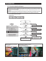
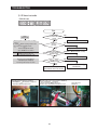
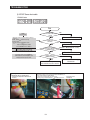
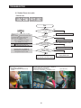
1
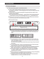
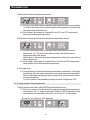
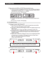
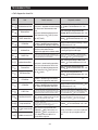
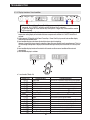
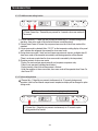
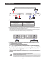
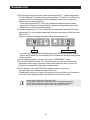
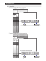
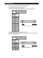
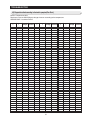
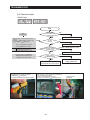
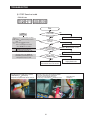
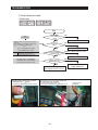
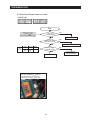
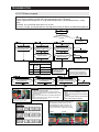
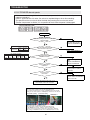
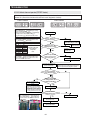
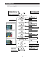
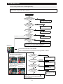
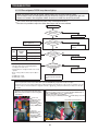
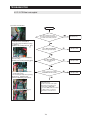
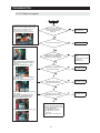
4. TROUBLESHOOTING
4-1. Function for failure diagnosis
40
4-1-1) TEST MODE
40
4-1-2) DISPLAY FUNCTION OF COMMUNICATION ERROR
41
4-1-3) SELF-DIAGNOSTIC FUNCTION
42
4-1-4) DISPLAY FUNCTION OF LOAD CONDITION
45
4-1-5) EXHIBITION MODE SETTING FUNCTION
46
4-1-6) OPTION SETTING FUNCTION
46
4-1-7) Option TABLE
49
4-2. Diagnostic method according to the trouble symptom
51
4-2-1) IF THE TROUBLE IS DETECTED BY SELF-DIAGNOSIS
52
4-2-2) IF FAN DOES NOT OPERATE
60
4-2-3) IF ICE MAKER DOES NOT OPERATE
61
4-2-4) IF DEFROST DOES NOT OPERATE (F,R DEF HEATER)
62
4-2-5) IF POWER IS NOT SUPPLIED
63
4-2-6) IF COMPRESSOR DOES NOT OPERATE
64
4-2-7) WHEN ALARM SOUND CONTINUOUS WITHOUT STOP
65
4-2-8) IF PANEL PCB DOES NOT WORK NORMALLY
67
4-2-9) IF PANTRY PANEL PCB IS NOT WORKING NORMALLY
68
4-2-10) WHEN REFRIGERATOR ROOM LAMP DOES NOT LIGHT UP
69
4-2-11) IF ICE WATER IS NOT SUPPLIED
70
4-2-12) IF WATER IS NOT SUPPLIED
71
39
TROUBLESHOOTING
4-1) Function for failure diagnosis
4-1-1. Test mode (manual operation / manual defrost function)
● If Power Freeze & Fridge temperature control Key on the front of panel are pressed
simultaneously for 8 seconds , it will be changed to the test mode and all displays on the front
of panel will be off.
● If any key on the front of panel is pressed within 15 seconds after the test mode, it will be
operated as below sequence :
manual operation(fresh food compartment) manual defrost of fresh food compartment(rd)
manual defrost of fresh food and freezer compartments (Fd) Cancel(Display all off).
● If any key on the front of panel is not pressed within 15 seconds after the test mode, the test
mode will be canceled and it will be returned to previous mode.
1) Manual operation function
-2℉(-19℃)is Recommended
38℉(3℃)is Recommended
①
①
If Power Freeze Key + Fridge Key are pressed simultaneously for 8 seconds,
(displays are all off)
It will be changed to the test mode (manual operation) by pressing any key
1-1) If any key is pressed once in test mode, blinks "FF" on the display and it indicates the
refrigerator has entered the manual operation. At this moment, buzzer beeps as an
alarm.
1-2) If manual operation is selected, comp will run at once without 5 minutes delay in any
mode. If the refrigerator is on the defrost cycle at the moment, defrost will be finished
and manual operation will begin.
(Be careful if manual operation get started at the moment of comp off, over load could
be occurred)
1-3) If manual operation works, comp & f-fan operate continuously for 24 hours and fresh
food compartment will be controlled by the setting temperature.
1-4) When the manual operation runs, setting temperature will be selected automatically as
below: freezer compartment -14 (-25 ), fresh food compartment 33.8 (1 ).
1-5) During manual operation, Power Freeze & Power Cool function will not be worked.
If a function is selected, the power function icon of the selected function will be off
automatically after 10 seconds.
1-6) Manual operation can be canceled during manual operation by turning on the appliance
after power off(reset) or choosing the step 4) test cancel mode.
1-7) Alarm(0.25 sec ON/ 0.75 sec OFF) will beep continuously until manual operation is
completed and there is no function to make the sound stop.
40
TROUBLESHOOTING
2) Manual defrost(fresh food compartment) function
2-1) If any key is pressed one more time during manual operation(fresh food compartment),
"rd" shows in the display and then manual operation will be canceled at once and fresh
food compartment will be defrosted.
2-2) At this moment, alarm beeps for 3 seconds(0.1 sec ON/ 1 sec OFF) during manual
defrost(fresh food compartment) function.
3) Simultaneous manual defrost(fresh food and freezer compartments) function
3-1) If any key is pressed one more time during manual defrost(defrost of fresh food
compartment, "rd"), "Fd" shows on the display and then fresh food and freezer
compartments defrost will operate.
Manual defrost of Fresh food and freezer compartments are followed by manual defrost
freezer compartment.
3-2) At this moment, alarm beeps for 3 seconds (0.5 sec ON/ 0.5 sec OFF) during manual
defrost function of fresh food and freezer compartment.
4) Test cancel mode
4-1) During defrosting of fresh food and freezer compartments simultaneously, if the display
panel change to the test mode and test button is pressed one more time, defrosting of
fresh food and freezer compartments will be canceled at the same time and will return
to the normal operation.
Or, all test functions will be canceled by turning main power ON again after it OFF.
4-1-2. Display function of Communication error
1) Display function when Panel MAIN MICOM communication has error
1-1) If there is no answer for 10 seconds after the panel micom received the requirement of
communication, "Pc - Er" display on the panel PCB will be ON/OFF alternately until the
communication error is canceled. (0.5 sec ALL ON, 0.5 sec ALL OFF alternately)
(0.5 sec ALL ON, 0.5 sec ALL OFF alternately)
41
TROUBLESHOOTING
2) Display function when MAIN LOAD MICOM communication has error
2-1) If there is no answer for 20 seconds after the main micon received the requirement of
communication from load MICOM, "Lc - Er" display on the panel PCB will be ON/OFF
alternately until the communication error is canceled.
(0.5 sec ALL ON, 0.5 sec ALL OFF alternately)
2-2) Also pantry room display will be ON/OFF alternately until the communication error is
canceled.
(0.5 sec ALL ON, 1.5 sec ALL OFF alternately)
4-1-3. Self-diagnostic function
1) Self-diagnostic function in the Initial power ON
1-1) Micom operates self-diagnostic function to check the temperature sensor condition
within 1 second when the refrigerator turned On initially.
1-2) If bad sensor is detected by the self-diagnostic function, the applicable display LED will
blink for 0.5 sec.
At this moment, there is no beep sound.(Refer to self-diagnostic CHECK LIST)
1-3) Self-diagnostic button is recognized only when the error is displayed by the bad sensor.
Display does not operate normally but temperature control will be controlled by the
emergency operation.
1-4) When the error is detected by self-diagnosis, the error can be canceled automatically if
all troubled sensors are corrected or Self-diagnostic function key (Power Freeze +
Power Cool ) are pressed simultaneously for 8 seconds.
(Return to normal display mode)
-2℉(-19℃)is Recommended
38℉(3℃)is Recommended
①
①
If Power Freeze Key + Power Cool Key are pressed simultaneously
for 8 seconds, the error mode by self-diagnosis will be canceled.
2) Self-diagnostic function during normal operation
-2℉(-19℃)is Recommended
38℉(3℃)is Recommended
①
①
42
TROUBLESHOOTING
2-1) If Power Freeze + Power Cool Key are pressed simultaneously for 6 seconds during
normal operation, the temperature setting display will operate for 2 seconds (ON/OFF
0.5sec each).
If Power Freeze + Power Cool Key are pressed simultaneously for 8 seconds (including
above 2 seconds), self-diagnostic function will be selected.
2-2) At this moment, self-diagnostic function will be returned with buzzer sound 'ding-dong'.
If there is an error, display of error will be operated for 30 seconds and then return to
normal condition whether problem is corrected or not.
(Refer to self-diagnosis CHECK LIST)
2-3) Input by button is not accepted during self-diagnostic function.
Self-diagnosis CHECK LIST
Trouble item
Display LED
Trouble contents
NO
Ice Maker Sensor Error
R-1ICE MAKER SENSOR part error
1
R-Sensor Error
R-1FF SENSOR part error
2
R-DEF-Sensor Error
R-1FF defrost SENSOR part error
3
R-FAN Error
R-1FF inner fan motor part error
4
Ice Maker Error
R-1ICE MAKER operation error
5
R-DEF.Error
R-1FZ defrost part error
6
Ambient-Sensor Error
F-1External SENSOR part error
7
F-Sensor Error
F-1FZ SENSOR part error
8
F-DEF-Sensor Error
F-1FZ defrost SENSOR part error
9
F-FAN Error
F-1FZ inner fan motor part error
10
C-FAN Error
F-1Machine room fan motor part error
11
F-DEF. Error
F-1FZ defrost part error
12
Pantry-Damper-Heater Error
R-10Damper Heater open/wire error
13
Pantry-Sensor Error
R-10Pantry Room SENSOR part error
14
Panel Main MICOM communication error
15 Panel Main MICOM communication Error F-10L M communication Error
F-10LOAD Main MICOM communication error
16
F-10
F-1
R-10
R-1
43
TROUBLESHOOTING
Self-diagnostics check list
Item
Trouble contents
R-1-
Ice Maker Sensor Error
R-1-
R-Sensor Error
R-1-
R-DEF-Sensor Error
Display error : separation of sensor housing
part, contact error, disconnection, short
circuit
Display error of detecting temperature of
sensor: more than 149 (+65°C) or less
than -58 (-50°C)
R-1-
R-FAN Error
R-1-
Ice Maker Error
LED
R-1-
R-DEF. Error
F-1-
Ambient-Sensor Error
F-1-
F-Sensor Error
F-1-
DEF-Sensor Error
F-1-
F-FAN Error
F-1-
C-FAN Error
F-1-
F-DEF. Error
R-10-
Pantry-Damper-Heater Error
R-10-
Pantry-Sensor Error
F-10-
Panel Main communication Error
F-10-
Display error during operation of applicable
fan motor : Feed Back signal line contact
error, separation of motor wire, motor error
Display error : ice making kit is harvested
more than 3 times and level error
** Apply to the applicable Ice Maker model.
Display error : separation of fresh food compartment defrost heater housing
part, contact error, disconnection, short circuit or temperature fuse error.
Display error : the defrosting does not finish though fresh food compartment
defrost is heating continuously for more than 80 minutes.
Display error : sensor housing separation,
contact error, disconnection, short circuit
Display error by detecting temperature of
sensor: more than 149 (+65°C) or less
than -58 (-50°C)
Display error during operation of applicable
fan motor : Feed Back signal line contact
error, motor wire separation, motor error
Display error during operation of applicable
fan motor : Feed Back signal line contact
error, motor wire separation, motor error
Display error : separation of freezer compartment defrost heater housing
part , contact error, disconnection, short circuit or temperature fuse error.
Display error : the defrosting does not finish though fresh food compartment
compartment defrost is heating continuously for more than 70 minutes.
Diagnostic method
When checking the voltage of MAIN PCB CN90
#3 CN90#4 : shall be between 4.5V~1.0V.
When checking the voltage of MAIN PCB
CN30#6 CN75#1:shall be between 4.5V~1.0V
When checking the voltage of MAIN PCB
CN30#7 CN75#:shall be between 4.5V~1.0V
Voltage of MAIN PCB CN75 Orange
shall be between 7V~12V
Gray
After replacing ice maker, check the operation
by turning the appliance ON again.
After separating MAIN PCB CN70,CN71 from PCB, check the
resistance value between CN70 White CN71 Orange shall be
102(441) ohm 7%. (Resistant value is varied by the input power)
Check 0 Ohm : heater short, Ohm : wire / bimetal Open.
When checking the voltage of MAIN PCB
CN32#1 #4 : shall be between 4.5V~1.0V.
When checking the voltage of MAIN PCB
CN30#3 CN75#1:shall be between 4.5V~1.0V
When check the voltage of MAIN PCB
CN30#4 CN75#1:shall be between 4.5V~1.0V
Voltage of MAIN PCB CN75 Yellow
shall be between 7V~12V.
Voltage of MAIN PCB CN75 Sky-blue
shall be between 7V~12V.
Gray
Gray
After separating MAIN PCB CN70,CN71 from PCB, check the
resistant value between CN70 brown CN71 Orange shall be
102(220) ohm 7%. (Resistant value is varied by input power)
Check 0 Ohm : heater short, Ohm : wire / bimetal Open.
Display error when open error is detected by damper After separating MAIN PCB CN91from PCB, check the resistant
heater : separation of Damper Heater housing part, value between Black brown wire shall be 145 ohm 7%.
Check 0 Ohm : heater short, Ohm : wire / bimetal Open.
contact error, disconnection, short circuit
Display error : separation of sensor housing, contact error,
disconnection, short circuit.
Display error by detecting temperature of sensor: more
than 149 (+65°C) or less than -58 (-50°C)
Display "oP/LC-Er" in the panel with alarm :
MICOM MAIN LOAD communication error
MICOM MAIN PANEL communication error
LC-Er is displayed when the Option is not
Load Main communication Error
equivalent with the right value
44
When checking the voltage of MAIN PCB
CN30#8 #9 : shall be between 4.5V~1.0V.
Actually, it is desirable to recheck the condition with
the oscilloscope after replacing Main and Panel
PCB.
TROUBLESHOOTING
4-1-4. Display function of Load condition
-2℉(-19℃)is Recommended
38℉(3℃)is Recommended
①
②
①
If Power Freeze Key + Power Cool Key are pressed simultaneously for 6
seconds, ALL ON/OFF will blink with 0.5interval for 2 seconds.
If take the finger off from above keys and press Fridge Key, load condition mode
will be started.
1) If Power Freeze Key + Power Cool Key are pressed simultaneously for 6 seconds during normal operation, the
temperature setting display of fresh food and freezer compartments will blink ALL ON/OFF with 0.5 for 2
seconds.
2) At this moment, If Fridge Key after Power Freeze Key + Power Cool Key is pressed, load condition display
mode will be returned with alarm.
3) Load condition display mode shows the load that micom signal is outputting.
However, It means that micom signal is outputting, it does not mean whether load is operating or not. That is to
say that though load operation is displayed, load could not be operated by actual load error or PCB relay error
etc.
4) Load condition display function will maintain for 30 seconds and then normal condition will be returned
automatically.
5) Load condition display is as below.
F-1
R-1
F-10
R-10
Load mode Check list
Display LED
Display contents
Operation contents
R-1R-1R-1R-1R-1R-1F-1- , ALL LED Off
R1F-1F-1F-1F-1R-10R-10F-10F-10-
R-FAN High
R-FAN Low
R-DEF Heater
Start Mode
Overload condition
Low temperature condition
Normal Condition
Exhibition Mode
COMP.
F-FAN High
F-FAN Low
F-DEF Heater
C-FAN High
C-FAN Low
French Heater
Pantry Room Damper Open
When fresh food compartment fan high operates, applicable LED ON
When fresh food compartment fan low operates, applicable LED ON
When fresh food compartment defrost heater operates, LED ON
Initial power ON refrigerator, LED ON
When ambient temperature is more than 93 (34°C), LED ON
When ambient temperature is less than 72 (22°C), LED ON
When ambient temperature is between 73 (23°C) ~ 91 (33°C), LED ON
Display mode, LED ON
When compressor operates, applicable LED ON
When freezer compartment fan high operates, applicable LED ON
When freezer compartment fan low operates, applicable LED ON
When freezer compartment defrost heater operates, LED ON
When compressor fan high operates, applicable LED ON
When compressor fan low operates, applicable LED ON
When french heater operates, applicable LED ON
When damper open, applicable LED ON
45
TROUBLESHOOTING
4-1-5. Exhibition mode setting function
-2℉(-19℃)is Recommended
①
38℉(3℃)is Recommended
①
If Power Freeze Key + Freezer Key are pressed for 3 seconds, show room mode will
be started.
1) If Power Freeze Key + Freezer Key are pressed simultaneously for 3 seconds during normal
operation, show room mode will be started with buzzer sound(ding-dong).
2) If above Power Freeze & Freezer Key are pressed one more time, show room mode will be
canceled.
3) If show room mode is selected, blinks "OF-OF" on the temperature setting display of the panel
and it indicates the refrigerator has entered the show room mode.
4) During show room mode, if fresh food and freezer compartments sensors are higher than 65
show room mode will be canceled automatically and freezing operation will be returned.
(There is no buzzer sound when the show room mode is canceled by the temperature)
5) Operation contents of show room mode
- Display, Fan motor and etc operate normally, not to operate compressor only.
- Defrost is not operated. (including french heater)
- Display function of the initial real temperature is finished.
- Under the condition of show room mode, show room mode will be operated when Power On
after Power OFF.
4-1-6. Option setting function
If Freezer Key + Fridge Key are pressed simultaneously for 12 seconds during normal
operation, fresh food and freezer compartments temperature display will be changed to option
setting mode.
KEY operation method for changing to option mode
-2℉(-19℃)is Recommended
38℉(3℃)is Recommended
①
①
If Freeze Key + Fridge Key are pressed simultaneously for 12 seconds, option
setting mode will be started.
46
TROUBLESHOOTING
KEY control method after converting to option mode
Code
Down
Reference
Value Down
①
①
-2℉(-19℃)is Recommended
Code
Up
38℉(3℃)is Recommended
Code
Reference
Value
Reference
Value Up
Key control in option mode
Power Freeze Key
Freezer Key
Power Cool key
Fridge key
Code Down key
Code Up key
Reference Value down key
Reference Value Up key
If the display changes to option setting mode, all displays will be off except freezer and
fridge compartments temperature display as below.
(Fresh food and freezer compartments case will be explained only because all options
are operated with the same method according to the option table.)
Code
Reference Value
1) For example, if you want to change freezer compartment standard temperature to 28.4 (2°C) by operating option, do as below.
This function is for changing the standard temperature.
In -2 (-19°C) of current temperature of freezer compartment, if you make the temperature
lower to 28.4 (-2°C) by the option, the standard temperature would be controlled -6 (-21°C)
Therefore, if you change the setting of temperature option to -2 (-19°C) on the panel, the
appliance will be operated with -6 (-21°C).
It means that standard temperature is controlled 28.4 (-2°C) less than setting temperature in
the display.
NOTE
Basically, option function has cleared data at shipping process.
Therefore, almost all setting value are "0".
Check the product information manual or specifications because setting value could be
changed particularly for the purpose of improving product at mass producing process.
47
TROUBLESHOOTING
2) After changing to the option mode, fresh food compartment "0" , freezer compartment
"0" will be displayed. ( Basically fresh food compartment "0", freezer "0" would be set at
shipping process, but setting value could be changed for the purpose of improving
product at mass producing process.)
- If fresh food compartment "0" shows only, temperature reference value of freezer
compartment will be set and current freezer compartment temperature code will be
displayed on the freezer temperature display.
3) If freezer compartment "4" is set as below freezer compartment code after fresh food
compartment "0 is set, standard temperature of freezer compartment will be lower than
28.4 (-2.0°C).
(Refer to the picture "changing the freezer compartment temperature")
Code
Reference Value
: If you wait for 20 seconds after completing the setting, MICOM will save the setting
value to the EEPROM and normal display will be returned and the option setting mode
will be canceled.
4) Option changing method as above is the same as all RF266/265** model.
5) By the same method as above, it is possible to control the fresh food compartment
temperature, water supply, ice-maker harvest temperature/time, defrost return time,
hysteresis by temperature, notch gap by temperature etc.
6) Option function is set in the EEPROM at shipping process in the factory.
You would better not to change the option of your own.
Completing the setting is that option function return to normal display after 20 seconds.
Do not turn off the appliance before returning to the normal display mode.
NOTE
Option setting function exists in the other items.
We will skip the explanation of the other functions by the option because it is
associated with refrigerator control function and is not needed at SERVICE.
(Please do not set the other options except above SERVICE Manual.)
48
TROUBLESHOOTING
4-1-7. Option TABLE
1) Temperature changing table of freezer compartment
Set item
Freezer Temp Shift
MODEL
RF265/266/RF26NB
Reference
Value
Fridge Room 7-SEG
0
Setting value
Temp.
FZ
compartment compensation
Code
32 (0.0°C)
0
1
31.1 (-0.5°C)
2
30.2 (-1.0°C)
3
29.3 (-1.5°C)
4
28.4 (-2.0°C)
5
27.5 (-2.5°C)
6
26.6 (-3.0°C)
7
25.7 (-3.5°C)
8
32.9 (+0.5°C)
9
33.8 (+1.0°C)
10
34.7 (+1.5°C)
11
35.6 (+2.0°C)
12
36.5 (+2.5°C)
13
37.4 (+3.0°C)
14
38.3 (+3.5°C)
15
39.2 (+4.0°C)
Code
Reference Value
ex) If you want to change the freezer standard temperature to 28.4 (-2°C)
2) Temperature changing table of fresh food compartment
Set item
Freezer Temp Shift
MODEL
RF265/266/RF26NB
Reference
Value
Fridge Room 7-SEG
1
Setting value
Temp.
FZ
compartment compensation
Code
0
32 (0.0°C)
1
31.1 (-0.5°C)
2
30.2 (-1.0°C)
3
29.3 (-1.5°C)
4
28.4 (-2.0°C)
5
27.5 (-2.5°C)
6
26.6 (-3.0°C)
7
25.7 (-3.5°C)
8
32.9 (+0.5°C)
9
33.8 (+1.0°C)
10
34.7 (+1.5°C)
11
35.6 (+2.0°C)
12
36.5 (+2.5°C)
13
37.4 (+3.0°C)
14
38.3 (+3.5°C)
15
39.2 (+4.0°C)
ex) If you want to change the Fresh Food
compartment standard temperature to 35.6 (2°C)
Code
49
Reference Value
TROUBLESHOOTING
■Below options are applied to the applicable model with ice maker.
Do not set below options to the model without Ice Maker.
3) To change the ice maker harvest waiting time
This option controls the harvest waiting time for ice dispensing from Ice maker
Set item
Reference
Value
Setting value
ICE MAKER waiting time of ice making
Fridge Room 7-SEG
3
FZ
compartment
Code
Temp.
compensation
(mins)
0
58
1
57
2
56
3
55
4
54
5
53
6
52
7
51
8
50
9
49
10
48
11
47
12
46
13
45
14
59
15
60
Code
Reference Value
ex) If you want to change the waiting time to 60 minutes
4) To change the ice making sensor temperature of ice maker
This option Controls the standard temperature of judgment that is checking whether ice of ice
maker is frozen completely or not.
Set item
Reference
Value
Setting value
FZ
compartment
Code
ICE MAKER control the temperature of ice making
Fridge Room 7-SEG
4
Temp.
compensation
(mins)
0
1.4 (-17°C)
1
3.2 (-16°C)
2
5.0 (-15°C)
3
6.8 (-14°C)
4
8.6 (-13°C)
5
10.4 (-12°C)
6
-0.4 (-18°C)
7
2.2 (-19°C)
Code
Reference Value
ex) If you want to change the ice making sensor
temperature to 5.0 (-15°C)
50
TROUBLESHOOTING
4-2) Diagnostic method according to the trouble symptom(Flow Chart)
DATA1.Temperature table
Resistance value and MICOM port voltage of sensor according to the temperature
SENSOR CHIP : based on PX41C
℃
℉
-50
-49
-48
-47
-46
-45
-44
-43
-42
-41
-40
-39
-38
-37
-36
-35
-34
-33
-32
-31
-30
-29
-28
-27
-26
-25
-24
-23
-22
-21
-20
-19
-18
-17
-16
-15
-14
-13
-12
-11
-10
-9
-8
-7
-6
-58
-56.2
-54.4
-52.6
-50.8
-49
-47.2
-45.4
-43.6
-41.8
-40
-38.2
-36.4
-34.6
-32.8
-31
-29.2
-27.4
-25.6
-23.8
-22
-20.2
-18.4
-16.6
-14.8
-13
-11.2
-9.4
-7.6
-5.8
-4
-2.2
-0.4
1.4
3.2
5
6.8
8.6
10.4
12.2
14
15.8
17.6
19.4
21.2
Voltage Resistance
4.694
4.677
4.659
4.641
4.622
4.602
4.581
4.560
4.537
4.514
4.490
4.465
4.439
4.412
4.385
4.356
4.326
4.296
4.264
4.232
4.199
4.165
4.129
4.093
4.056
4.018
3.980
3.940
3.899
3.858
3.816
3.773
3.729
3.685
3.640
3.594
3.548
3.501
3.453
3.405
3.356
3.307
3.258
3.208
3.158
153319
144794
136798
129294
122248
115631
109413
103569
98073
92903
88037
83456
79142
75077
71246
67634
64227
61012
57977
55112
52406
49848
47431
45146
42984
40938
39002
37169
35433
33788
32230
30752
29350
28021
26760
25562
24425
23345
22320
21345
20418
19537
18698
17901
17142
℃
℉
-5
-4
-3
-2
-1
0
1
2
3
4
5
6
7
8
9
10
11
12
13
14
15
16
17
18
19
20
21
22
23
24
25
26
27
28
29
30
31
32
33
34
35
36
37
38
39
23
24.8
26.6
28.4
30.2
32
33.8
35.6
37.4
39.2
41
42.8
44.6
46.4
48.2
50
51.8
53.6
55.4
57.2
59
60.8
62.6
64.4
66.2
68
69.8
71.6
73.4
75.2
77
78.8
80.6
82.4
84.2
86
87.8
89.6
91.4
93.2
95
96.8
98.6
100.4
102.2
Voltage Resistance
3.107
3.057
3.006
2.955
2.904
2.853
2.802
2.751
2.700
2.649
2.599
2.548
2.498
2.449
2.399
2.350
2.301
2.253
2.205
2.158
2.111
2.064
2.019
1.974
1.929
1.885
1.842
1.799
1.757
1.716
1.675
1.636
1.596
1.558
1.520
1.483
1.447
1.412
1.377
1.343
1.309
1.277
1.253
1.213
1.183
51
16419
15731
15076
14452
13857
13290
12749
12233
11741
11271
10823
10395
9986
9596
9223
8867
8526
8200
7888
7590
7305
7032
6771
6521
6281
6052
5832
5621
5419
5225
5039
4861
4690
4526
4369
4218
4072
3933
3799
3670
3547
3428
3344
3204
3098
℃
℉
40
41
42
43
44
45
46
47
48
49
50
51
52
53
54
55
56
57
58
59
60
61
62
63
64
65
66
67
68
69
70
71
72
73
74
75
76
77
78
79
80
81
82
83
84
104
105.8
107.6
109.4
111.2
113
114.8
116.6
118.4
120.2
122
123.8
125.6
127.4
129.2
131
132.8
134.6
136.4
138.2
140
141.8
143.6
145.4
147.2
149
150.8
152.6
154.4
156.2
158
159.8
161.6
163.4
165.2
167
168.8
170.6
172.4
174.2
176
177.8
179.6
181.4
183.2
Voltage Resistance
1.153
1.124
1.095
1.068
1.040
1.014
0.988
0.963
0.938
0.914
0.891
0.868
0.846
0.824
0.803
0.783
0.762
0.743
0.724
0.706
0.688
0.670
0.653
0.636
0.620
0.604
0.589
0.574
0.560
0.546
0.532
0.519
0.506
0.493
0.481
0.469
0.457
0.446
0.435
0.424
0.414
0.404
0.394
0.384
0.375
2997
2899
2805
2714
2627
2543
2462
2384
2309
2237
2167
2100
2036
1973
1913
1855
1799
1745
1693
1642
1594
1547
1502
1458
1416
1375
1335
1297
1260
1225
1190
1157
1125
1093
1063
1034
1006
978
952
926
902
877
854
832
810
TROUBLESHOOTING
4-2-1. If the trouble is detected by self-diagnosis
- The error of sensor will be displayed on the front of display.
when the error of sensor is detected at initial power ON, the appliance will not operated and display
of abnormal sensor part will blink.
- The appliance will not stop operating when the error of sensor is detected during operation of the
appliance.
But normal freezing might be not operated if the appliance is operated by the emergency operation
mode. You would better to check the appliance according to the self-diagnosis of the manual.
1) If ICE Maker Sensor has trouble
ERROR Code
Start
DATA1.
Temperature table
** Measuring point of resistance value according to
Sensor **
ICE MAKER : CN90#3 #1 measuring resistance value
** 0 : Short trouble /
: Open trouble
Is MAIN PCB Connector
CN90 inserted correctly?
YES
Is ICE Maker Sensor
unit normal?
Refer to circuit diagram in the manual
Sensor MICOM/Connector number
ICE
Connector CN90#"4"(White) and
Maker CN1#"3"(Black) PCB common Ground
Voltage measured between 4.6V ~ 0.6V.
NO
Bad contact of connector/ insert correctly
NO
Replace the temperature sensor
YES
Is the voltage between
MAIN PCB Connector CN90#"4"(White) and
CN1#"3"(Black) normal?
NO(0.6V > Measurement < 4.6V)
YES
Measuring voltage of IC02 MICOM #30,
CN90#4(White) and CN1#3(Black) from
PCB typical Ground part are similar.
Is input voltage of IC02
MICOM #30 normal?
Recheck the wire connection part
NO
YES
No trouble with PCB and temperature sensor.
Recheck the bad contact of the connection.
Checking method of ICE Maker Sensor resistance CN90#
"3(White) #4"(White)
- Compare the temperature table after the measure.
Checking method of ICE Maker Sensor resistance
- Measure the voltage of Sensor Check Point #6(IC02 MICOM #30)
on PCB or CN90#4(White) CN1#3(Black)
- Compare the temperature table after the measure.
Measuring voltage of CN90#4(White) CN1#3(Black) are below.
52
Check the iced-solder, solder
bridging, disturbed solder.
typical PCB Ground
CN1#3(Black)
TROUBLESHOOTING
2) If R Sensor has trouble
ERROR Code
Start
DATA1.
Temperature table
Is MAIN PCB
Connector CN30 to CN75 inserted
correctly?
YES
** Measuring point of resistance value according to
Sensor **
R : CN30#6 CN75#1 measuring resistance value
** 0 : Short trouble /
: Open trouble
Is R Sensor
unit normal?
Refer to circuit diagram in the manual
Sensor MICOM/Connector number
Connector
CN30#6(White) to
R
CN1#3(Black) PCB typical Ground
Voltage measured between 4.6V ~ 0.6V.
NO
Bad contact of connector/ insert correctly
NO
Replace the temperature sensor
YES
Is the voltage between
MAIN PCB Connector CN30#6(White) to
CN1#3(Black) normal?
NO(0.6V > Measurement < 4.6V)
YES
Measuring voltage IC01 MICOM #54,
CN30#6(White) and CN1#3(Black)
from PCB typical Ground part are similar.
Is the input voltage to
IC01 MICOM #54 normal?
Recheck the wire connection part
NO
YES
No trouble with PCB and temperature sensor.
Recheck the bad contact of the connection.
Checking method of R Sensor resistance
CN30#6(White) CN75#1(Gray) Compare the
temperature table after the measure.
Checking method of R Sensor resistance
- Measure the voltage of Sensor Check Point #3(IC01 MICOM #54)
on PCB or CN30#6(White) CN1#3(Black)
- Compare the temperature table after the measure.
Measuring voltage of CN30#6(White)°ÍCN1#3(Black) are below.
53
Check the iced-solder, solder bridging,
disturbed solder.
typical PCB Ground
CN#3(Black)
TROUBLESHOOTING
3) If R DEF Sensor has trouble
ERROR Code
Start
DATA1.
Temperature table
Is MAIN PCB
Connector CN30 to CN75 inserted
correctly?
YES
** Measuring point of resistance value according to
Sensor **
R-DEF : CN30#7 CN75#1 measuring
resistance value
** 0 : Short trouble /
: Open trouble
Is R DEF Sensor
unit normal?
Refer to circuit diagram in the manual
Sensor MICOM/Connector Number
Connector
CN30-"7"(Sky-blue) and
RDEF CN1-"3"(Black)
PCB common Ground
Voltage measured between 4.6V ~ 0.6V.
NO
Bad contact of connector/ insert correctly
NO
Replace the temperature sensor
YES
Is the input voltage between
MAIN PCB Connector CN30#7(Skyblue)
to CN1#3(Black) normal?
NO(0.6V > Measurement < 4.6V)
YES
Measuring voltage of IC01 MICOM #57,
CN30#7(Sky-blue) and CN1#3(Black) from
PCB typical Ground part are similar.
Is the input voltage of IC01
MICOM # 57 normal?
Recheck the wire connection part
NO
YES
No trouble with PCB and temperature sensor.
Recheck the bad contact of the connection.
Checking method of R Sensor resistance
CN30#7(Sky-blue) CN75#1(Gray)
- Compare the temperature table after the
measure.
Check the iced-solder, solder bridging,
disturbed solder.
Checking method of R DEF Sensor resistance
- Measure the voltage of Sensor Check Point #4(IC01 MICOM #57) on
PCB or CN30#7Sky-blue) CN1#3(Black)
- Compare the temperature table after the measure.
Measuring voltage of CN30#7(Sky-blue) CN1#3(Black) are below.
54
typical PCB Ground
CN1#3(Black)
TROUBLESHOOTING
4) If Ambient Sensor has trouble
ERROR Code
Start
DATA1.
Temperature table
** Measuring point of resistance value according to
Sensor **
Ambient : CN32#1 #4 measuring resistance value
** Placed in the right top table of upper hinge.
** 0 : Short trouble /
: Open trouble
Is MAIN PCB
Connector CN32 inserted
correctly?
YES
Is Ambient Sensor
unit normal?
Refer to circuit diagram in the manual
Sensor MICOM/Connector number
Connector
CN32#1(White) to
Ambient CN1#3(Black)
PCB typical Ground
Voltage measured between 4.6V ~ 0.6V.
NO
Bad contact of connector/ insert correctly
NO
Replace the temperature sensor
YES
Is the voltage between
MAIN PCB Connector CN32#1(White)
to CN1#3(Black) normal?
NO(0.6V > Measurement < 4.6V)
YES
Measuring voltage of IC01 MICOM #59,
CN32#1(White) and CN1#3(Black) from
PCB typical Ground part are similar.
Is the input voltage of
IC01 MICOM #59 normal?
Recheck the wiring connection
NO
YES
No trouble with PCB and temperature sensor
Recheck the bad contact of the connection
Checking method of Ambient Sensor resistance
CN32#1(White) #4(White)
- Compare the temperature table after the
measure
Checking method of Ambient Sensor voltage
- Measure the voltage of Sensor Check Point #7(IC01 MICOM #59)
on PCB or CN32#1(White) CN1#3(Black)
- Compare the temperature table after the measure
Measuring voltage of CN32#1(White) CN1#3(Black) are below
55
Check the iced-solder, solder
bridging, disturbed solder
typical PCB Ground
CN1#3(Black)
TROUBLESHOOTING
5) If F Sensor has trouble
ERROR Code
Start
DATA1.
Temperature table
Are MAIN PCB
Connector CN30 to CN75
inserted correctly?
YES
** Measuring point of resistance value according to
Sensor **
F : CN30#3 CN75#1 measuring resistance value
** 0 : Short trouble /
: Open trouble
Is F Sensor
unit normal?
Refer to circuit diagram in the manual
Sensor MICOM/Connector number
Connector
CN30#3(Red) to
F
CN1#3(Black) PCB typical Ground
Voltage measured between 4.6V ~ 0.6V.
NO
Bad contact of connector/ insert correctly
NO
Replace temperature sensor
YES
Is the voltage between
MAIN PCB Connector CN30#3(Red) to
CN1#3(Black) normal?
NO(0.6V > Measurement < 4.6V)
YES
Measuring voltage of IC01 MICOM #52,
CN30#3(Red) and CN1#3(Black) from
PCB typical Ground part are similar.
Is the input voltage of
IC01 MICOM #52 normal?
Recheck the wiring connection
NO
YES
No trouble with PCB and temperature sensor
Recheck the bad contact of the connection
Checking method of F Sensor resistance
CN30#3(Red) CN75#1(Gray)
- Compare the temperature table after the measure
Checking method of F Sensor voltage
- Measure the voltage of Sensor Check Point #1(IC01COM #52) on
PCB or CN30#3(Red) CN1#3(Black)
- Compare the temperature table after the measure
Measuring voltage of CN30#3(Red) CN1#3(Black) are below.
56
Check the iced-solder, solder
bridging, disturbed solder
typical PCB Ground
CN1#3(Black)
TROUBLESHOOTING
6) If F DEF Sensor has trouble
ERROR Code
Start
DATA1.
Temperature table
Are MAIN PCB
Connector CN30 to
CN75 insert correctly?
YES
** Measuring point of resistance value according to
Sensor **
F-DEF : CN30#4 CN75#1 measuring resistance
value
** 0 : Short trouble /
: Open trouble
Is F DEF Sensor
unit normal?
Refer to circuit diagram in the manual
Sensor MICOM/Connector number
Connector
CN30#4(Orange) to
F DEF CN1#3(Black)
PCB typical Ground
Voltage measured between 4.6V ~ 0.6V.
NO
Bad contact of connector/ insert correctly
NO
Replace temperature sensor
YES
Is the voltage between
MAIN PCB Connector CN30#4(Orange)
to CN1#3(Black) normal?
NO(0.6V > Measurement < 4.6V)
YES
Measuring voltage of IC01 MICOM #53,
CN30#4(Orange) and CN1#3(Black) from
PCB typical Ground part are similar.
Is the input voltage of
IC01 MICOM #53 normal?
Recheck the wiring connection
NO
YES
No trouble with PCB and temperature sensor.
Recheck the bad contact of the connection.
Checking method of F DEF Sensor resistance
CN30#4(Orange) CN75#1(Gray)
- Compare the temperature table after the measure.
Checking method of F DEF Sensor voltage
- Measure the voltage of Sensor Check Point #1(IC01 MICOM
#52) on PCB or CN30#4(Orange) CN1#3(Black)
- Compare the temperature table after the measure
Measuring voltage of CN30#4(Orange) CN1#3(Black) are below
57
Check the iced-solder, solder
bridging, disturbed solder
typical PCB Ground
CN1#3(Black)
TROUBLESHOOTING
7) If Pantry Sensor has trouble
ERROR Code
Start
DATA1.
Temperature table
Is MAIN PCB
Connector CN30 insert
correctly?
YES
** Measuring point of resistance value according to
Sensor **
Pantry : CN30#8 #9 measuring resistance value
** 0 : Short trouble /
: Open trouble
Is Pantry Sensor
normal?
Refer to circuit diagram in the manual
Sensor MICOM/Connector number
Connector
CN30#8(White-black) to
Pantry CN1#3(Black)
PCB typical Ground
Voltage measured between 4.6V ~ 0.6V.
NO
Bad contact of connector/ insert correctly
NO
Replace temperature sensor
YES
Is the voltage between
MAIN PCB Connector CN30#8(Whiteblack)
to CN1#3(Black) normal?
NO(0.6V > Measurement < 4.6V)
YES
Measuring voltage of IC01 MICOM #58,
CN30#8(White-black) and CN1#3(Black)
from PCB typical Ground part are similar.
Is the input voltage of IC01
MICOM Pin# 58 normal?
Recheck the wiring connection
NO
YES
No trouble with PCB and temperature sensor.
Recheck the bad contact of the connection.
Checking method of Pantry Sensor resistance
CN30#8(White-black) #9(Gray)
- Compare the temperature table after the measure
Checking method of Pantry Sensor voltage
- Measuring voltage of Sensor Check Point #5(IC01 MICOM #58) on
PCB or CN30#8(White-black) CN1#3(Black)
- Compare the temperature table after the measure
Measuring voltage of CN30#8(white-black) CN1#3(Black) are below
58
Check the iced-solder, solder
bridging, disturbed solder
typical PCB Ground
CN1#3(Black)
TROUBLESHOOTING
8) If Pantry Room Damper Heater has trouble
ERROR Code
Start
Measure the resistance
between - after
CN90 connector open 145ohm
7%
Is Damper Heater
normal?(about145ohm)
NO
YES
Is MAIN PCB connector
(CN91) inserted correctly?
Replace Damper
NO
Bad contact of connector/ insert correctly
YES
Initial
Damper Damper
MICOM power On heater off heater On
#37
4.0V ~
condition 4.0V ~
0V
4.5V
4.5V
Is the input voltage of
IC02 MICOM #37 normal?
YES
Normal(recheck)
Checking method of Pantry Room Damper
resistance CN91#1(Black) #2(Brown)
**
: Open(wire disconnection, heater
disconnection) trouble 0 : Short trouble
59
NO
1) Recheck the wire
2) Replace PCB MAIN
TROUBLESHOOTING
4-2-2. If FAN does not operate
- The refrigerator of this model has BLDC FAN motor. BLDC motor is driven by DC 7~12V.
- On the normal condition of COMP ON, it operates together with F-FAN motor.
If door is opened and closed once at a high ambient temperature, it will be operated after 1 minute
delay.
Therefore, you are advised not to taken it for an error.
-. If there is a trouble, you should select the self-diagnostic function to check the trouble before power off.
Start
Is COMP ON ?
Execute manual
operation
Is the voltage between MAIN
PCB CN1#3 (Black) and CN75#4(Sky
-blue) around DC7~12V?
Is the voltage between MAIN
PCB CN1#3 (Black) and CN75#3
(Orange) around DC7~12V?
Is the voltage between MAIN
PCB CN1#3 (Black) and CN75#2
(Yellow) around DC7~12V?
FAN work normally
Is the voltage between MAIN
PCB CN1#3 (Black) and CN30#2
(Purple) around 0V?
Is the voltage between MAIN
PCB CN1#3 (Black) and CN30#1
(Black) around 5V?
Repair the connection
of Door switch
Door & MICOM State
F
R MICOM(#3)
Door MICOM
Right and Left
(#50)
Close 5V(High)
Open 0V(Low)
Does DC7~12V alternate with below
DC 2V between MAIN PCB CN1#3(Black)
and CN75#4(Sky-blue)
0V(Low)
5V(High)
Power ON with 5 minutes
delay after power OFF.
For preventing the over
load of compressor)
Does DC7~12V alternate with below
DC 2V between MAIN PCB CN1#3(Black)
and CN75#3(Orange)
In initial power to appliance, the compressor
and fans of fresh food/ freezer, compressor
fan operate. If freezer temperature is
sensed of 41 by momentary power
failure, fans will operate after 5 minutes.
Does DC7~12V alternate with
below DC 2V between MAIN PCB
CN1#3(Black) and CN75-#2(Yellow)
Replace MAIN PCB
F FAN pulse voltage
CN75#5(Black)
typical PCB Ground
CN10#3(Black)
The voltage measured around 2~3V
with multi-meter though the voltage is
very weak because of pulse signal
Reference
CN75-5(F),6(R),7(C)will generate the pulse signal when motor rotates.
These signals will be inputted into MICOM.
Unless signals are not inputted during motor operating, will be ON 10
seconds after fan Off. But if signals are not still entered, the above operation
will restart four times more.
If signals are not entered continuously, the motor will be restarted after 10
seconds.
This function is effective when the normal operation of motor would be
restrained by foreign matters such as ice.
Display for checking the self-diagnostic function
R FAN ERROR
F FAN ERROR
Expected causes
Check that if FAN-MOTOR has failure
itself.
Check that if wiring connection has bad
contact.
Check the input of the fan motor rotation
pulse when motor fan operates.
Checking method of R,F,C FAN Motor voltage
The voltage between PCB typical Ground CN1-"3"(Black) and
R FAN ; CN75#2(Yellow) shall be less than DC 7~12V.
F FAN ; CN75#3(Orange) shall be less than DC 7~12V.
C FAN ; CN75#4(Sky-blue) shall be less than DC 7~12V.
- Recheck if resistance values are different after measuring.
1) R-FAN
C FAN ERROR
60
2) F-FAN
typical PCB Ground
CN1#3(Black)
3) C-FAN
TROUBLESHOOTING
4-2-3. If ICE MAKER does not operate
1. Water is automatically supplied to the Ice maker by temperature & time and ice maker dispenses
cubed or crushed ice.
2. Power is applied to one of its wires. So, refer to its exploded diagram when disassembling.
3. The operation of the Ice maker shall be checked after pressing the Ice maker test switch.
(Freezer compartment Ice Maker) It is not possible to check when the power is disengaged.
Function ERROR Code
Start
Does the self-diagnostic
function for detecting position of Ice maker at the
initial Power ON?
1) Check the wiring connection
2) Replace the ICE MAKER KIT
Micom(IC02) Condition
#29
(Test Switch)
Ready
Operation
5V
0V
Micom(IC02) Condition
Reverse- ReturnRotation Rotation Rotation
Ready
#27
5V
0V
5V
0V
Does ice maker rotate when Ice
maker test switch is pressed?
Replace the ICE MAKER KIT
Is the input voltage of IC02
MICOM #27 normal?
Ready
5V
1) Check the wiring connection
part
2) Replace ICE MAKER KIT
3) Replace the MAIN PCB
Is water supplied after a
certain time?
1) Replace the Water Valve
* refer to operation condition of
water valve
Is Ice maker sensor
unit normal?
1) Repair ICE Maker Sensor
* Refer to solution when ICE Maker
Sensor has trouble
No trouble with PCB and temperature sensor.
Recheck bad contact of the connection.
Checking method of ICE Maker voltage
The voltage between PCB typical Ground CN1#3(Black) and
1) Test switch operation(press selected) ; CN90#5(Gray) shall be DC 0V.
Waiting for test switch operation ; CN90#5(Gray) shall be less than DC 5V.
1)Test Switch operating
1)Test Switch waiting
typical PCB Ground
CN1-"3"(Black)
Checking method of ICE Maker voltage
The voltage between PCB typical Ground CN1#3(Black) and
2) IC02 MICOM #27 voltage ; wait(5V)
rotate clockwise(0V)
rotate counterclockwise(5V)
horizontal condition(0V)
wait(5V)
* The voltage of MICOM #27 and Connector CN90#7(Purple) are same.
61
TROUBLESHOOTING
4-2-4. If defrost does not operate (F,R DEF Heater)
- If defrost has trouble, select the self-diagnostic function to detect the error of defrost heater before
Power Off. (Check the function with refer to the self-diagnostic function)
R DEF ERROR
F DEF ERROR
**Measuring point of resistance value according to heater**
F-DEF : CN70#9(Brown) CN71#9(Orange) measuring
resistance value(55(220) ohm 7%)
R-DEF(Ice Pipe parallel) : CN70#7(White) N71#9(Orange)
measuring resistance value(105(407) ohm 7%)
** 0 : Short trouble /
: Open(bimetal, heater) trouble
Start
**Measuring point of resistance value according to sensor **
F-DEF : CN30#4 CN75#1 measuring resistance value
R-DEF : CN30#7 CN75#1 measuring resistance value
** 0 : Short trouble /
: Open trouble
Are the all deforst
heater normal?
Check the bimetal, heater
disconnection, wiring connection etc.
Resistance value of sensor according to temperature
86
68
50
32
14
-4
-22
(30
(20
(10
(0
(-10
(-20
(-30
)
)
)
)
)
)
)
4.22
6.05
8.87
13.29
20.42
32.23
52.41
If you need the
temperature with detail,
refer to DATA1.
temperature
table
**Measuring point of resistance value according to sensor **
F-DEF : CN30#4 CN75#1 measuring resistance value
R-DEF : CN30#7 CN75#1 measuring resistance value
** 0V: Short trouble / 5V: Open trouble
Refer to self-diagnostic
function in the manual
Is defrost sensor by
self-diagnostic normal?
Replace the
applicable sensor
Is the temperature of
defrost sensor lower
than 53.6 (12°C)?
Manual defrosting of fresh food
and freezer compartments
operate simultaneously.
manual operation for a certain time
If Power Freeze Key + Fridge Key are pressed
simultaneously for 8 seconds and then select any key,
3rd test mode(manual defrosting) will be operated.
Is power applied to
each defrost heaters?
Recheck the applicable
sensor.
Reference If defrost sensor
temperatures of fresh food and
freezer compartments are higher
than 50 (10 ), 53.6 (12 ) by
the heating from heater, heating
would be finished and will return
to cooling operation after a pause.
Checking method of F,R DEF Heater resistance value
F FEF ; CN70#9(Brown)
CN71#9(Orange)
R FEF ; CN70#7(White)
CN71#9(Orange)
- Recheck if resistance values are different after the test
1) F DEF Heater
2) R DEF Heater
Does the system return
to cooling operation after
heating for specified time?
Normal
Is connection terminal of
MAIN PCB part normal?
Repair connection terminal
Check bimetal, heater itself,
disconnection etc.
Replace failure Relay or
replace PCB ASS'Y
62
TROUBLESHOOTING
4-2-5. If Power is not supplied
Caution
At the power of main PCB, the
AC115(220)V power and a highvoltage over DC 170(325)V are
occurred. Please take care of
yourself on repair and measurement.
Start
- Refer to function and
reference parts in the manual
when check the MAIN PCB
Is plug connected in?
Connect plug again,
check the plug loosening
Is power 115(220)V
both terminals of SMPS
PCB CN1?
Check in SMPS PBA
Checking method of SMPS voltage CN1
input ; CN1#1(Red) #3(Black) AC voltage
Check the assembly and wire
connection
Is fuse on the SMPS
PCB down?
1) Replace FUSE AC 250V 2.0A
2) Replace SMPS assembly
Is DC170(325)V applied
both
terminals of BD1+,-
1) Check PCB PATTERN and replace BD1
2) Replace PCB ASS'Y
Checking method of SMPS 2nd output
voltage CN2 input ; CN2#1(Red)
#3(Black) same as C19 terminals..
DC 5V
0.3V
Is DC5.8V
applied between TOP
switch 246Y C to S?
Replace PCB ASS'Y
Is 12V applied both
terminals of C16?
1) Replace U4 (D10LC20U)
2) Replace PCB ASS'Y
Is 5V applied both
terminals of C19?
Checking method of SMPS 2nd output
voltage CN2 input ; CN2#5(Yellow)
#3(Black) same as C16 terminals.
DC 12V
0.6V
1) Replace REG1 (KA7805)
2) Replace PCB ASS'Y
Does Panel PCB
operate normally?
1) Check assembly wire and repair
2) Replace Panel PCB
Is normal load such
as Relay?
1) Check the contact of lead wire
2) Replace the applicable relay / PCB MAIN
Is there any PCB
soldering, short,
breakage?
- Check MAIN PCB connection
- Check the connections
between cabinet to door
- Check the connections
between door to panel PCB
1) Solder again
2) Replace PCB MAIN
Normal(Recheck)
63
TROUBLESHOOTING
4-2-6. If compressor does not operate
Start
Did 5 mins pass
after COMP OFF ?
Check after
5 minutes
Refer to test function
in the manual
Does compressor work
with manual operation?
Did buzzer of manual operation sound?
(Check certainly after manual operation)
Is freezer sensor
normal?
Is IC02 MICOM #8
High?(5V)
Open and repair
the connection
1) Replace MICOM
2) Replace PCB
Is the temperature sensor
of MAIN PCB normal?
Is IC72 #15 about
0.8V?
Repair the sensor
and replace PCB
1) Replace IC72 Driver IC(TD62083AP)
2) Replace PCB
Refer to circuit diagram
in the manual
OPEN and repair
the connection
Is CN71 connector
normal?
Check bad contact of
connector
Is COMP ASS'Y
normal?
Replace COMP ASS'Y
Normal (recheck)
Checking method of voltage PCB typical
Ground CN1#3(Black) and
1) IC02 MICOM #8 ; voltage High(5V 0.5V)
IC02 MICOM #8, COMP operating
Checking method of voltage
PCB typical Ground CN1#3(Black) and
1) IC72 #15 : Voltage Low(0V)
64
typical PCB Ground
CN1#3(Black)
TROUBLESHOOTING
4-2-7. When alarm sound continuous without stop(related with buzzer sound)
If 'ding-dong' sounds continuously
Start
Is door closed
completely?
Door is ajar
Remove causes after comprehending
the conditions of interference by door
gasket, food etc.
Is water penetrated
into the door switch?
Replace Door S/W
Door & MICOM State
F
R MICOM(#3)
Door MICOM
Right and Left
(#50)
Close
Open
5V(High)
0V(Low)
Is the input
voltage of main #50 and #3
changed at door-open,
door-close?
0V(Low)
5V(High)
Repair wire connection and
Door S/W
Is the connector(CN30)
inserted correctly?
Connector is not inserted,
Repair bad contact
Separate the door switch and check if
the measured value of unit is
changed from 0 to
according
to switch ON/OFF.
* FF Door Switch is magnetic switch .
(it can be operated when door
magnet is combined with)
Is the door switch unit
normal?
Replace Door S/W
Recheck MAIN PCB and
door switch
If 'beep-beep' sounds continuously
Start
Is manual operation
/defrost selected?
Enforce the cancelation the
manual operation/ defrost function
or power On after power Off
Does buzzer sounds
when power On again?
MAIN PCB normal
Check if there is any short parts
due to foreign matters and the
test jumper part in the mainPCB.
65
TROUBLESHOOTING
If buzzer does not sound
Buzzer is installed on the panel PCB in this model.
If buzzer does not sound when button is pressed, manual operation is started and door is opened,
should separate panel PCB and check the breakage of buzzer and bad soldering.
It is very hard to repair the panel PCB because it consists of SMD assemblies.
It is recommended to replace assembly PCB when the failure associated with panel is occurred
except the minor error such as switch pressing error, surface peeling off and so on.
Start
Does it sound
'dingdong' if press a button
on the front panel?
MAIN PCB normal,
BUZZER normal
Does it make a
sound of 'dooropen' alarm when
you are opening the door of freezer or
fridge more than 2 minutes?
Check the panel PCB with reference
of <how to check Panel Display>
Is the damage
or breakage of the buzzer in
the panel PCB?
Replace(repair) buzzer
Replace Panel PCB
Did lead of a component
fall on the vibration plate of
buzzer?
Replace buzzer
Replace Panel PCB
Recheck the button pressing
force and mechanical problem
66
TROUBLESHOOTING
4-2-8. If Panel PCB does not work normally
When lighting of Panel PCB is disabled or only some LED Lamp are disabled
Be careful to repair because display of this model is installed in the MICOM of internal PCB.
It is recommend to replace PCB MAIN after checking except specified solder touch.
Start
Refer to electronic circuit
diagram in the manual or
circuit diagram on the back
side of the appliance
Is the connector of
upper hinge cover
inserted correctly?
Reinsert connector,
Repair bad contact
Is MAIN PCB
connector (CN50)
inserted correctly?
Reinsert connector of MAIN PCB
Is Top Table
Panel PCB connector
inserted correctly?
Reinsert connector,
Repair bad contact
Is lighting operate
normally when replace
Panel-PCB?
Panel PCB itself has trouble.
Check the wire of Top Table Panel - disconnection, short between wires
Check the wires between fresh food compartment upper cabinet - MAIN PCB - disconnection, short between wires
If Panel PCB KEY is not selected
If it is not repaired with using the basic checking method as above
Are one or more keys
pressed continuously?
Reassemble the PCB ASS'Y /
Enforce the cancelation of pressed keys
Is the PCB system
still operated by separating
of the mechanism?
Reassemble the PCB ASS'Y /
Enforce the cancelation of pressed keys
Is the lighting operated
normally when replace the
Panel-PCB ?
Panel PCB itself has trouble.
Check the wires of Top Table Panel - disconnection, short between wires.
Check the wires of fresh food compartment upper cabinet - disconnection, short between wires.
Check the short/open of the panel communication and power supply circuit in MAIN PCB.
67
TROUBLESHOOTING
4-2-9. If Pantry Panel PCB is not working normally
You should check the display after door opening because the display of this model operates only when
the fresh food compartment door is opened.
Start
Does fresh food
compartment door switch
operate normally?
Check and repair the switch
* Refer to<how to repair door switch>
Is the connector of
pantry room in fresh food
compartment inserted
correctly?
Reinsert Connector,
Repair bad contact
Is MAIN PCB
Connector (CN78) inserted
correctly?
Reinsert connector in MAIN PCB
Is signal of MAIN
PCB CN78 normal?
If Panel Key is not selected
Check voltage/Replace MAIN PCB
Is the lighting
operated when replace Pantry
Panel-PCB?
Panel PCB itself has trouble.
Check the wires of Pantry Room - disconnection, short between wires
Recheck the control circuit of MAIN PCB Pantry Panel
Check the wire assembling between Panel MAIN
typical PCB Ground
CN1#3(Black)
If Panel Panel PCB Key is not selected
If it is not repaired with using the basic checking method as above
Checking method of voltage Based on
PCB typical Ground CN1#3(Black)
1) Key voltage ; CN78#1"(Purple)
1) select(operating) (0V)
2) normal(about5.0V 0.5V)
Is a key pressed
continuously?
Is the PCB system
still operated by separating
of the mechanism?
2) LED part voltage ; CN78-"7"(Yellow),
Voltage of CN78 is same as
"8"(Pink)
IC74 #12,#11 voltage.
- Display On (0.7V 0.3V)
Is the lighting operated
when replace Pantry
Panel-PCB?
Reassemble PCB ASS'Y /
Enforce the cancelation of
pressed keys
Reassemble PCB ASS'Y /
Enforce the cancelation of
pressed keys
Convertible compartment Panel
PCB itself has trouble.
- Display Off (9.7V 1V)
Is a normal voltage
outputted from MAIN PCB IC74
in the key operating?
Replace MAIN PCB
Check the short of MAIN
Panel wire
Check the wire of Pantry Room - disconnection, short
between wires
Check the short/open of the pantry panel lighting
circuit in MAIN PCB.
68
TROUBLESHOOTING
4-2-10. When refrigerator ROOM Lamp does not light up
1. When you replace the lamp of freezer, please power OFF to avoid an electric shock.
2. Please keep in mind you could get burnt by the excessive heating of an incandescent light bulb.
3. Bimetal is installed in the refrigerator LAMP. Check that if LAMP may be OFF by bimetal.
The case of fresh food compartment(room) lamp will be explained only.
Because it is possible to repair the other room lamps with the same method.
Start
Is the inside lamp
filament cut?
Repair the inside lamp
Fresh food compartment
Lamp is applied only.
Is Lamp OFF by
bimetal operating?
Wait for returning time
of bimetal
Door & MICOM State
Door
Close
Open
F
MICOM
(#50)
R MICOM(#3)
5V(High)
0V(Low)
0V(Low)
5V(High)
Right and Left
Reference
* The interior lamp relay operates lighting/lightout
according to door open / close.
* If interior lamp does not light, check the noise of relay
operation.
* Noise of relay operation sounds every Door Open /
Close.
* F-LAMP Relay -- RY75
* R-LAMP Relay -- RY76
Is the connection
point of R-door switch
normal?
Repair door switch
Is the control relay
of the inside lamp in PCB
normal?(RY76)
Replace PCB and
Replace Relay
Check the connection of RDoor
switch and repair the inside lamp
socket
Reference
If the door is opened, the contact of door switch will be opened and MICOM will get applied 5V to finally sense Open.
If 5V has been sensed over two minutes afterwards, Door-Open alarm will sound Ding-Dong for 10 seconds in a oneminute cycle. For
that reason, if the door switch has failure, the refrigerator can make a Ding-Dong sound per a oneminute cycle. Please note the step
for its service.
When measure lamp resistance to the Wire
Resistance can be changed by Lamp input voltage.
(Actual measurement is below, it can be changed by
performance)
Checking method of Door Switch voltage
- Measuring voltage of Sensor Check Point #5(IC01 MICOM #58) on
PCB or CN30#8(White-black)
CN75#1(Gray)
- Compare time table after measuring
Measuring voltage of CN30#8(white-black) CN75#1(Gray) are below
Fresh food
compartment lamp
CN70#1(Red)
CN71#1 (Blue) ;
10(33)Ohm 3 Ohm
Lamp ; 60W + 60W
typical PCB Ground CN10#3"(Black)
Freezer
compartment lamp
CN70#1(Red)
CN71#3 (Purple) ;
15(66)Ohm 5 Ohm
Lamp ; 60W
69
TROUBLESHOOTING
4-2-11. If ICE Water is not supplied
typical PCB Ground CN1#3(Black)
Start
Is the confirming sound of
the valve operation heard when
Ice maker test switch pushed?
Normal(Check Ice
water valve hose)
Checking method of voltage Based on
PCB typical Ground CN1#3(Black)
1) Check the voltage of IC73#4(same voltage
as IC02 #12)
- ICE Water valve operating (about 5V 0.5V)
Based on PCB typical Ground CN1#3(Black)
2) IC73 #13 voltage
- ICE Water valve operating (about 0.7V 0.5V)
3) Check the voltage of ICE Water Valve
operating(AC voltage)
=> For checking the Relay RY79 operating.
CN70#1(Red) CN73#7(Purple)
- ICE Water valve waiting (about AC 0V)
- ICE Water valve operating (about AC 110V
20%)
Does Main PCB MICOM
#12 have high (5V)output?
Check soldering
short/Replace PCB
Does Main PCB IC73
#13 have about 0.7V
output?
Check soldering
short/Replace PCB
Is the contact point of main
PCB RELAY RY79 normal?
Check soldering
short/Replace PCB
MAIN PCB normal
-- Need to check the other parts
Check the wire between Ice
water valve MAIN PCB
Ice water valve itself has trouble
or bad contact of connector
Check the connection hose
70
TROUBLESHOOTING
4-2-12. If Water is not supplied
Start
Checking method of Valve resistance (Must
power off for checking)
Resistance can be changed by input voltage.
CN70#1 (Red)
CN73#5 (White-black)
- resistance value ; 388Ohm
7%)
** 0 : Short trouble /
: Open trouble
Is the confirming sound of
the valve operation heard
when dispenser switch
pushed?
Is the valve unit normal?
Normal(Check Ice
water valve hose)
Replace Valve
typical PCB Ground CN1#3(Black)
Is the voltage of PCB IC01
MICOM #15 changed 0V~5V
according to switch On/Off?
Checking method of voltage
Based on PCB typical Ground CN1#3(Black)
1) Check voltage of IC73# (same voltage as
IC01#64)
- Water valve operating (about 5V 0.5V)
Does Main PCB IC73 #3
have about 5V input?
Check soldering
short/Replace PCB
Does Main PCB IC73 #14
have about 0.7V output?
Check soldering
short/Replace PCB
Is the contact point of main
PCB RELAY RY7A normal?
Check soldering
short/Replace PCB
Based on PCB typical Ground CN1#3(Black)
2) IC73 #14 voltage
- Water valve operating (about 0.7V 0.5V)
3) Check the voltage of Water Valve operating
(AC voltage)
=> For checking the Relay RY7A operating.
CN70#1(Red) CN73#5(White-black)
- ICE Water valve waiting (about AC 0V)
- ICE Water valve operating (about AC 110(230)V
20%)
1) Check the dispensing
lever
2) Check switch unit/ wiring
connection
3) Replace PCB
MAIN PCB normal
-- Need to check the other parts
Check the wire between water
valve MAIN PCB
Ice water valve itself has
trouble or bad contact of
connector
Check the connection hose
71