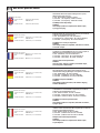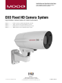
1
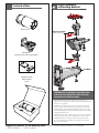
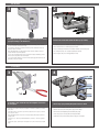
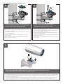
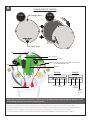
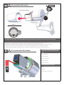
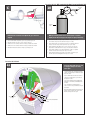
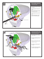
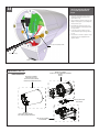
Installation and Operation Instructions
Before attempting to connect or operate this product,
please read these instructions completely.
EXO
Fixed
HD
Camera
System
High Definition Camera Systems for Harsh Environments
EXVF5C-1...................720P, 12x optical zoom, Vandal resistant with wall / pole mount
EXPF5C-1...................720P, 12x optical zoom, Pressurized with wall / pole mount
EXVF5C-2...................1080P, 10x optical zoom, Vandal resistant with wall / pole mount
EXPF5C-2...................1080P, 10x optical zoom, Pressurized with wall / pole mount
Moog Inc.
Sensor and Surveillance Systems
© 2013, Moog Inc. All Rights Reserved
3650 Woodhead Drive Northbrook, IL. USA 60062
+1.847.498.0700 Fax: +1.847.498.1258 www.moogS3.com:
81-IN5518 092314
IMPORTANT SAFEGUARDS
1
Read these instructions.
2
Keep these instructions.
3
Heed all warnings
4
Follow all instructions.
5
Do not use this apparatus near water.
6
Clean only with damp cloth.
7
CAUTION
RISK OF ELECTRIC SHOCK
DO NOT OPEN
Do not block any of the ventilation openings. Install in accordance with the
manufacturers instructions.
8
9
SAFETY PRECAUTIONS
Cable Runs- All cable runs must be within permissible distance.
CAUTION: TO REDUCE THE RISK OF
ELECTRIC SHOCK, DO NOT REMOVE
COVER ( OR BACK). NO USER- SERVICEABLE PARTS INSIDE. REFER SEVICING
TO QUALIFIED SERVICE PERSONNEL.
Mounting - This unit must be properly and securely mounted to a supporting
structure capable of sustaining the weight of the unit.
Accordingly:
a. This installation should be made by a qualified service person and should conform
to all local codes.
b. Care should be exercised to select suitable hardware to install the unit, taking into
account both the composition of the mounting surface and the weight of the unit.
10 Do not install near any heat sources such as radiators, heat registers, stoves, or other
apparatus ( including amplifiers) that produce heat.
11 Do not defeat the safety purpose of the polarized or grounding-type plug. A
polarized plug has two blades with one wider than the other. A grounding type
plug has two blades and a third grounding prong. The wide blade or the third
prong are provided for your safety. When the provided plug does not fit into your
outlet, consult an electrician for replacement of the obsolete outlet.
12 Protect the power cord from being walked on or pinched particularly at plugs,
convenience receptacles, and the point where they exit from the apparatus.
13 Only use attachment/ accessories specified by the manufacturer.
14 Use only with a cart, stand, tripod, bracket, or table specified by the manufacturer,
or sold with the apparatus. When a cart is used, use caution when moving the cart/
apparatus combination to avoid injury from tip-over.
15 Unplug this apparatus during lighting storms or when unused for long periods of time.
16 Refer all servicing to qualified service personnel. Servicing is required when the
apparatus has been damaged in any way, such as power-supply cord or plug is
damaged, liquid has been spilled of objects have fallen into the apparatus, the
The lightning flash with an arrowhead symbol,
within an equilateral triangle, is intended to
alert the user to the presence of non-insulated
“dangerous voltage” within the product’s
enclosure that may be of sufficient magnitude
to constitute a risk to persons.
Este símbolo se piensa para alertar al usuario a la presencia
del “voltaje peligroso no-aisIado” dentro del recinto de los
productos que puede ser un riesgo de choque eléctrico.
Ce symbole est prévu pour alerter I’utilisateur à la presence
“de la tension dangereuse” non-isolée dans la clôture de
produits qui peut être un risque de choc électrique.
Dieses Symbol soll den Benutzer zum Vorhandensein der
nicht-lsolier “Gefährdungsspannung” innerhalb der
Produkteinschließung alarmieren die eine Gefahr des
elektrischen Schlages sein kann.
Este símbolo é pretendido alertar o usuário à presença “di
tensão perigosa non-isolada” dentro do cerco dos produtos
que pode ser um risco de choque elétrico.
Questo simbolo è inteso per avvertire I’utente alla presenza
“di tensione pericolosa” non-isolata all’interno della
recinzione dei prodotti che può essere un rischio di scossa
elettrica.
apparatus has been exposed to rain or moisture, does not operate normally, or
has been dropped.
Be sure to periodically examine the unit and the supporting structure to make sure that the integrity
of the installation is intact. Failure to comply with the foregoing could result in the unit separating
from the support structure and falling, with resultant damages or injury to anyone or anything struck
by the falling unit.
UNPACKING
Unpack carefully. Electronic components can be
damaged if improperly handled or dropped. If an item
appears to have been damaged in shipment, replace
it properly in its carton and notify the shipper.
Be sure to save:
1 The shipping carton and packaging material.
They are the safest material in which to make future
shipments of the equipment.
2 These Installation and Operating Instructions.
SERVICE
If technical support or service is needed, contact us at
the following number:
TECHNICAL SUPPORT
AVAILABLE 24 HOURS
1 - 800 - 554 -1124
The exclamation point within an equilateral
triangle is intended to alert the user to
presence of important operating and
maintenance (servicing) instructions in the
literature accompanying the appliance.
Este símbolo del punto del exclamation se piensa para
alertar al usuario a la presencia de instrucciones importantes
en la literatura que acompaña la aplicación.
Ce symbole de point d’exclamation est prévu pour alerter
l’utilisateur à la presence des instructions importantes dans
la littérature accompagnant l’appareil.
Dieses Ausruf Punktsymbol soll den Benutzer zum
Vorhandensein de wichtigen Anweisungen in der Literatur
alarmieren, die das Gerät begleitet.
Este símbolo do ponto do exclamation é pretendido alertar o
usuário à presença de instruções importantes na literatura
que acompanha o dispositivo.
Questo simbolo del punto del exclamaton è inteso per
avvertire l’utente alla presenza delle istruzioni importanti nella
letteratura che accompagna l'apparecchio.
MADEIN
USA
BUY AMERICA COMPLIANT • COUNTRY OF ORIGIN U.S.A.
Product Warranty Registration
Register Your Products Online
www.moogS3.com/technical-support/product-registration
Moog values your patronage. We are solely committed to providing you with the highest quality products and
superior customer service. With 3-Year and 5-Year warranties (depending on the product purchased) we stand
behind every product we sell.
See full warranty details at www.moogS3.com/technical-support/warranty-plan/
:
• Simple and Trouble-Free RMA process
• Product / software updates
• Special promotions
• Eliminate the need to archive purchase documents such as receipts, purchase orders, etc.
Limited Warranty for Moog Products
Moog - Decatur Operations, subsequently referred to as “Manufacturer,” warrants these products to be free from defects in material or workmanship as follows:
PRODUCT CATEGORY
PARTS \ LABOR
All Enclosures and Electronics
Five (5) Years
Accessory Brackets
Five (5) Years
Controllers
Three (3) Years
Power Supplies / IR Illuminators
Three (3) Years
Poles / PolEvators / CamEvator
Three (3) Years
Warrior Series™ / Q-View™
Three (3) Years
SView Series
Three (3) Years 6 months if used in auto scan / tour operation
DeputyDome™, NiteTrac™, Igloo Dome, PurgeDome™
Three (3) Years 6 months if used in auto scan / tour operation
EXO Series Dome and Fixed Camera Systems*
Three (3) Years 6 months if used in auto scan / tour operation
EXO Series GeminEye Visible and Thermal Camera Systems
One (1) Year
™
™
™
™
During the labor warranty period, to repair the Product, Purchaser will either return the defective product, freight prepaid, or deliver it to Manufacturer at Moog Decatur
Operations, 2525 Park Central Boulevard, Decatur, Georgia, 30035. The Product to be repaired is to be returned in either its original carton or a similar package affording
an equal degree of protection with a RMA # (Return Materials Authorization number) displayed on the outer box or packing slip. To obtain a RMA# you must contact our
Technical Support Team at 800.554.1124, extension 101. Manufacturer will return the repaired product freight prepaid to Purchaser. Manufacturer is not obligated to
provide Purchaser with a substitute unit during the warranty period or at any time. After the applicable warranty period, Purchaser must pay all labor and/or parts charges.
The limited warranty stated in these product instructions is subject to all of the following terms and conditions.
TERMS AND CONDITIONS
1. NOTIFICATION OF CLAIMS: WARRANTY SERVICE: If Purchaser believes that the Product is defective in material or workmanship, then written notice with an explanation
of the claim shall be given promptly by Purchaser to Manufacturer. All claims for warranty service must be made within the warranty period. If after investigation,
Manufacturer determines the reported problem was not covered by the warranty, Purchaser shall pay Manufacturer for the cost of investigating the problem at its then
prevailing per incident billable rate. No repair or replacement of any Product or part thereof shall extend the warranty period of the entire Product. The specific warranty on
the repaired part only shall be in effect for a period of ninety (90) days following the repair or replacement of that part or the remaining period of the Product parts warranty,
whichever is greater.
2. EXCLUSIVE REMEDY: ACCEPTANCE: Purchaser’s exclusive remedy and Manufacturer’s sole obligation is to supply (or pay for) all labor necessary to repair any Product
found to be defective within the warranty period and to supply, at no extra charge, new or rebuilt replacements for defective parts.
3. EXCEPTIONS TO LIMITED WARRANTY: Manufacturer shall have no liability or obligation to Purchaser with respect to any Product requiring service during the warranty
period which is subjected to any of the following: abuse, improper use, negligence, accident, or acts of God (i.e., hurricanes, earthquakes), modification, failure of the
end-user to follow the directions outlined in the product instructions, failure of the end-user to follow the maintenance procedures recommended by the International Security
Industry Organization, written in product instructions, or recommended in the service manual for the Product. Furthermore, Manufacturer shall have no liability where a
schedule is specified for regular replacement or maintenance or cleaning of certain parts (based on usage) and the end-user has failed to follow such schedule; attempted
repair by non-qualified personnel; operation of the Product outside of the published environmental and electrical parameters, or if such Product’s original identification
(trademark, serial number) markings have been defaced, altered, or removed. Manufacturer excludes from warranty coverage Products sold AS IS and/or WITH ALL FAULTS
and excludes used Products which have not been sold by Manufacturer to the Purchaser. All software and accompanying documentation furnished with, or as part of the
Product is furnished “AS IS” (i.e., without any warranty of any kind), except where expressly provided otherwise in any documentation or license agreement furnished with
the Product. ANY COST ASSOCIATED WITH REMOVAL OF DEFECTIVE PRODUCT AND INSTALLATION OF REPLACEMENT PRODUCT IS NOT INCLUDED IN THIS WARRANTY.
4. PROOF OF PURCHASE: The Purchaser’s dated bill of sale must be retained as evidence of the date of purchase and to establish warranty eligibility.
DISCLAIMER OF WARRANTY
EXCEPT FOR THE FOREGOING WARRANTIES, MANUFACTURER HEREBY DISCLAIMS AND EXCLUDES ALL OTHER WARRANTIES, EXPRESS OR IMPLIED, INCLUDING, BUT
NOT LIMITED TO ANY AND/OR ALL IMPLIED WARRANTIES OF MERCHANTABILITY, FITNESS FOR A PARTICULAR PURPOSE AND/OR ANY WARRANTY WITH REGARD TO ANY
CLAIM OF INFRINGEMENT THAT MAY BE PROVIDED IN SECTION 2-312(3) OF THE UNIFORM COMMERCIAL CODE AND/OR IN ANY OTHER COMPARABLE STATE STATUTE.
MANUFACTURER HEREBY DISCLAIMS ANY REPRESENTATIONS OR WARRANTY THAT THE PRODUCT IS COMPATIBLE WITH ANY COMBINATION OF NON-MANUFACTURER
PRODUCTS OR NON-MANUFACTURER RECOMMENDED PRODUCTS PURCHASER MAY CHOOSE TO CONNECT TO THE PRODUCT.
LIMITATION OF LIABILITY
THE LIABILITY OF Manufacturer, IF ANY, AND PURCHASER’S SOLE AND EXCLUSIVE REMEDY FOR DAMAGES FOR ANY CLAIM OF ANY KIND WHATSOEVER, REGARDLESS
OF THE LEGAL THEORY AND WHETHER ARISING IN TORT OR CONTRACT, SHALL NOT BE GREATER THAN THE ACTUAL PURCHASE PRICE OF THE PRODUCT WITH RESPECT
TO WHICH SUCH CLAIM IS MADE. IN NO EVENT SHALL MANUFACTURER BE LIABLE TO PURCHASER FOR ANY SPECIAL, INDIRECT, INCIDENTAL, OR CONSEQUENTIAL
DAMAGES OF ANY KIND INCLUDING, BUT NOT LIMITED TO, COMPENSATION, REPLACEMENT LABOR COSTS, REIMBURSEMENT, OR DAMAGES ON ACCOUNT OF THE LOSS
OF PRESENT OR PROSPECTIVE PROFITS OR FOR ANY OTHER REASON WHATSOEVER.
* NOTE
Moog will repair or replace, at its option, any equipment which is damaged by transient voltage surge/spike or lightning strike (an “Occurrence”), while properly connected
to wired AC power line with protective ground. Any repair or modification of the equipment done by someone other than Moog voids the warranty.
Form 500-911 081913
!
English
Electrical Specifications
EXO Fixed
Power Input:
- 24VAC model
- PoE
30W max. (with heater)
IEEE 802.3-AT
- 12VDC model
18W max. (with heater)
Entrada de energía:
- 24VAC modelos
30W max. (con calefacción)
- PoE
IEEE 802.3-AT
Español
- 12VDC modelos
18W max. (con calentador)
Entrada de energía:
- 24VAC modèles 30W max. (con calefacción)
- PoE
IEEE 802.3-AT
- 12VDC modèles
18W max. (con calentador)
Entrada de energía:
- 24VAC Modelle
30W max. (con calefacción)
- PoE
IEEE 802.3-AT
- 12VDC Modelle
18W max. (con calentador)
El fijo EXO sistema de cámaras HD está diseñada para recibir (3)
entradas de energía diferentes. Ellos son:
1). PoE - (Factory Ready - EX * 1 F5C los modelos)
2). 24 voltios de CA - (Factory Ready - EX * 1 F5C los modelos)
3). 12 Volt DC - (Factory Ready - EX-1 * F5C12 modelos)
PoE Midspan se vende por separado:
MS30WA
30 W midspan, 802.3af compatible, 100-240V de entrada,
3 enchufe clavijas.
Le système de caméra HD EXO fixe est conçu pour accepter (3)
différentes entrées d'alimentation. Ils sont les suivants:
1). PoE - (usine Ready - EX * Les modèles F5C-1)
2). 24 Volt AC - (usine Ready - EX * Les modèles F5C-1)
3). 12 Volt DC - (usine Ready - EX * F5C12-1 modèles)
Die Feste EXO HD Camera System wurde entwickelt, um (3)
unterschiedlichen Eingangsleistungen zu akzeptieren. Es sind dies:
1). PoE - (Fabrik Ready - EX * F5C-1-Modelle)
2). 24 Volt AC - (Fabrik Ready - EX * F5C-1-Modelle)
3). 12 Volt DC - (Fabrik Ready - EX * F5C12-1-Modelle)
PoE Midspan Separat erhältlich:
MS30WA
30 W midspan, 802.3at-konform, 100-240VAC Eingang,
3 Zinken Netzstecker.
Entrada de energía:
- 24VAC modelos
30W max. (con calefacción)
- PoE
IEEE 802.3-AT
- 12VDC modelos
18W max. (con calentador)
Portuguese
O EXO Sistema de Câmera HD fixo é projetado para aceitar (3)
entradas de energia diferentes. Eles são:
1). PoE - (Fábrica de Pronto - EX * F5C-1 modelos)
2). 24 Volt AC - (Fábrica de Pronto - EX * F5C-1 modelos)
3). 12 Volts DC - (Fábrica de Pronto - EX * F5C12-1 modelos)
PoE Midspan vendido separadamente:
MS30WA
30 W midspan, 802.3at compatível, 100-240V de entrada,
3 plugue pinos.
Entrada de energía:
- 24VAC modelli
30W max. (con calefacción)
- PoE
IEEE 802.3-AT
- 12VDC modelli
Italiano
PoE Midspan Sold Separately:
MS30WA
30 W midspan, 802.3at compliant, 100-240Vac Input,
3 prong power plug.
Injecteur PoE vendu séparément:
MS30WA
30 W mi-portée, 802.3at conforme, 100-240VAC Input,
3 broches prise d'alimentation.
Français
Deutsch
The Fixed EXO HD Camera System is designed to accept (3)
different power inputs. They are:
1). PoE - (Factory Ready - EX*F5C-1 models)
2). 24 Volt AC - (Factory Ready - EX*F5C-1 models)
3). 12 Volt DC – (Factory Ready - EX*F5C12-1 models)
18W max. (con calentador)
Il sistema di telecamere fisse EXO HD è progettato per accettare (3)
ingressi di potenza differenti. Essi sono:
1). PoE - (Fabbrica Pronti - EX * F5C-1 modelli)
2). 24 Volt AC - (Fabbrica Pronti - EX * F5C-1 modelli)
3). 12 Volt DC - (Fabbrica Pronti - EX * F5C12-1 modelli)
Midspan PoE venduti separatamente:
MS30WA
30 W midspan, 802.3at compliant, 100-240Vac Input,
3 spina tripolare.
Contents of Box
!
Proper Assembly
of Mounting Bracket
EXO Fixed
Main Camera
Wiring Access Holes:
Must be rear facing
Wall Mount
(mount varies based on application)
Base Mount
Hardware Packet:
Mount Gasket
Screws
CAUTION: When assembling the mounting bracket,
make sure all the wiring access holes are facing
towards the rear of the base mount.
• PRECAUCIÓN: Al montar la consola de montaje, cerciórese de que todos los
agujeros de acceso del cableado son revestimiento hacia la parte posterior del portal
bajo del acceso de los montaje.
• ATTENTION : En assemblant le support, assurez-vous que toutes les ouvertures
d'accès de câblage sont revêtement vers l'arrière du portail bas d'accès de bâtis.
• VORSICHT: Wenn Sie die Schienenplatte zusammenbauen, stellen Sie sicher, dass
alle VerdrahtungsZugangslöcher Einfassung in Richtung zur Rückseite des niedrigen
Einfassungszugangsportals sind.
• CUIDADO: Ao montar o suporte, certifique-se que todos os furos de acesso da fiação
são revestimento para a parte traseira do portal baixo do acesso das montagens.
• ATTENZIONE: Nel montare il montaggio - la staffa, si assicura che tutti i fori di
accesso dei collegamenti siano rivestimento verso la parte posteriore del portale
basso di accesso dei supporti.
Suggested Hardware for the Mounting Holes:
• (4) 5/16” Flat Washer • (4) 5/16” Lock Washer
(4) 5/16” - 18 (or M8 for metric) x minimum 1 ¼” Hex Head Bolt
WALL MOUNTING
1
2
If running wire through a conduit to the housing mount, first install
appropriate fittings to the mount base.
Attach mount to wall with suitable hardware (not provided).
• Si se ejecuta a través de un cable de conducto a la carcasa de montaje, primero instale los
accesorios adecuados para la base de montaje.
• Si vous utilisez le câble dans un conduit à la monture logement, installez d'abord raccords
appropriés à la base de monture.
• Wenn Laufen Draht über eine Leitung mit dem Gehäuse montieren, installieren Sie zuerst
geeignete Armaturen an der Halterung Basis.
• Se você estiver executando fio através de um canal para a montagem de habitação, primeiro
instale acessórios apropriados à base de montagem.
• Ate el montaje a la pared con el hardware conveniente (no proporcionado).
• Attachez le bâti au mur avec le matériel approprié (non fourni).
• Bringen Sie Einfassung zur Wand mit der verwendbaren Hardware an (nicht bereitgestellt).
• Una a montagem à parede com a ferragem apropriada (não fornecida).
• Attacchi il supporto alla parete con fissaggi adatti (non forniti).
• Se l'esecuzione del filo attraverso un condotto al monte degli alloggi, prima installare raccordi
appropriati per la base di montaggio.
POLE MOUNTING
4
3
TAB
If attaching to pole, first break away tabs with pliers and remove
(4) strap plugs.
Thread straps (not provided) through the mount as shown.
• Si atan al poste, el primeros rompen lejos lengüetas con los alicates y quitan (4) los enchufes
de la correa.
•
Pase las correas (no incluidos) a través del soporte como se muestra.
•
Sangles de la discussion (non fournies) dans le support comme indiqué.
• Si attachant au poteau, les premiers cassent loin des étiquettes avec des pinces et enlèvent
(4) des prises de courroie.
•
Themen-Riemen (nicht mitgeliefert) durch die Halterung wie gezeigt.
•
Correias do Tópico (não fornecidos) através da montagem imediata.
•
Cinghie di discussione (non in dotazione) attraverso il supporto come illustrato.
• Bei der Befestigung zum Pfosten, brechen erste weg Vorsprünge mit Zangen und entfernen
(4) Bügelstecker.
• Se unindo ao pólo, o primeiros quebram afastado abas com alicates e removem (4) plugues
da cinta.
• Se attaccando al palo, i primi rompono via le linguette con le pinze e rimuovono (4) la cinghia
tappa.
Pole or Wall Mount (Use Steel Straps to Mount to Pole)
5
6
Gasket Nipples
Crimp
Cable Ties
Cable
Cable
Pierce the gasket nipples (as needed). Place the gasket as shown.
Pass wires without connectors thru gasket and nipples.
Crimp the connectors as needed. Then use cable ties
on the nipples to secure, leave an extra 2” of cable.
•
Alimente el cable a través del soporte, perfore las entrerroscas de la junta (según lo necesitado).
Coloque la junta como se muestra.
•
Crimp los conectores según sea necesario. A continuación, utilice bridas para cables en los
pezones para asegurar, deje un 2 extra "del cable.
•
Alimentez le câble par la parenthèse, percez les mamelons de garniture (comme nécessaire).
Placez la garniture comme montrée.
•
Sertir les connecteurs si nécessaire. Ensuite, utiliser des attaches câbles sur les mamelons
pour sécuriser, laisser un 2 supplémentaire "de câble.
•
Ziehen Sie Kabel durch Haltewinkel ein, durchbohren Sie die Dichtungsnippel (wie gebraucht).
Setzen Sie die Dichtung wie gezeigt.
•
Crimp die Anschlüsse je nach Bedarf. Dann nutzen Sie Kabelbindern an den Brustwarzen zu
sichern, lassen einen zusätzlichen 2 "Kabel.
•
Alimente o cabo através do suporte, perfure os bocais da gaxeta (como necessário). Coloc a
gaxeta como mostrada.
•
Cravar os conectores conforme necessário. Em seguida, use abraçadeiras nos mamilos para
garantir, deixe um 2 extra "de cabo.
•
Alimenti il cavo tramite la staffa, perfori gli ugelli della guarnizione (come stato necessario).
Disponga la guarnizione come indicata.
•
Crimpare i connettori se necessario. Quindi utilizzare fascette sui capezzoli per fissare, lasciare
un 2 in più "di cavo.
7
Place the camera on the bracket, carefully feed the wires and connectors through the housing and into the rear cavity.
Use the provided captive screws and the 5mm Allen key (included) to mount.
•
•
•
•
•
Coloca la carcasa en el soporte, se alimentan cuidadosamente los cables y conectores a través del alojamiento y dentro de la cavidad trasera. Use los tornillos suministrados y la llave Allen de 5 mm (incluido) para montar.
Placer le boîtier sur le support, nourrir soigneusement les câbles et les connecteurs à travers le boîtier et dans la cavité arrière. Utilisez les vis imperdables fournies et la clé Allen de 5mm (inclus) pour monter.
Legen Sie das Gehäuse auf der Konsole, es vorsichtig die Kabel und Stecker durch das Gehäuse und in den hinteren Hohlraum. Verwenden Sie die mitgelieferten unverlierbaren Schrauben und die 5mm
Inbusschlüssel (im Lieferumfang) zu montieren.
Colocar a caixa do suporte, com cuidado alimentar os fios e ligações através do invólucro e para dentro da cavidade traseira. Use os parafusos fornecidos ea chave Allen de 5 mm (incluído) para montar.
Posizionare la custodia sulla staffa, fare avanzare i cavi e connettori attraverso l'alloggiamento e nella cavità posteriore. Utilizzare le viti fornite e la chiave Allen da 5 mm (in dotazione) per montare.
8
FACING REAR OF CAMERA
STEP
1
(B- Completely loosen)
STEP
2
(A- Slightly loosen)
(B)
RJ45 / PoE Input
DETAIL
M
DATA
DETAIL
N
Alarm IN 1
POWER *(Shipped from factory for 24Vac input. For 12Vdc input;
see 12Vdc ADDENDUM section)
Alarm IN 2
Detail M
(A)
Speaker Audio
Ground
(+)
Detail N*
Mic
Ground Negative
DC (-)
AC (NEU)
Positive
DC (+)
AC (Live)
Make all final connections in the rear cavity. To do so, rotate the rear cover by slightly loosing the screw marked (A) and completely loosing the
screw marked (B). Then make all of the nessecary wiring connections.
•
Para girar la cubierta posterior, afloje levemente el (a) marcado tornillo y afloje totalmente el (b) marcado tornillo. Entonces haga todas las conexiones nessecary del cableado.
•
Afin de tourner la couverture arrière, détachez légèrement le (a) marqué par vis et détachez complètement le (b) marqué par vis. Établissez alors tous les rapports nessecary de câblage.
•
Um die hintere Abdeckung zu drehen, lösen Sie etwas das Schraube signifikante (a) und lösen Sie vollständig das Schraube signifikante (b). Stellen Sie dann alle nessecary Verdrahtungsbeziehungen her.
•
A fim girar a tampa traseira, afrouxe ligeiramente o (a) marcado parafuso e afrouxe completamente o (b) marcado parafuso. Faça então todas as conexões nessecary da fiação.
•
Per girare la copertura posteriore, allenti un po'la vite contrassegnata (A) e completamente allenti la vite contrassegnata (B). Allora faccia tutti collegamenti nessecary dei collegamenti.
9A
!
To Access the Micro SD Card Slot:
Loosen (2) screws
FIRST: MAKE SURE UNIT IS POWERED OFF COMPLETELY
5mm
Allen
Wrench
USE FORCE TO SPERATE
See
DETAIL A
________DETAIL A___________
FACING REAR OF ENCLOSURE
ALLEN
WRENCH
HOLE
SLOTS
Thoroughly loosen the (2) captive screws (shown in DETAIL A) with provided 5mm Allen Key (included) to remove the front part of the camera system.
• Completamente afloje los dos (2) tornillos (que se muestra en detalle A) con la llave Allen de 5 mm suministrado (incluido) para quitar la parte frontal del sistema de cámaras.
• Complètement desserrer l'(2) vis imperdables (représenté en détail A) avec fourni 5mm Clé Allen (inclus) pour retirer la partie avant du système de caméra.
• Gründlich lockern die (2) unverlierbaren Schrauben (im Detail gezeigt A) versehen mit 5mm Inbusschlüssel (im Lieferumfang enthalten), um den vorderen Teil des Kamera-System zu entfernen.
• Completamente soltar a (2) parafusos (mostrados em detalhe A) fornecido com cinco milímetros Chave Allen (incluído) para remover a parte da frente do sistema de câmera.
• Accuratamente allentare la (2) viti di fissaggio (mostrato in dettaglio A) fornito con 5 millimetri chiave a brugola (inclusa) per rimuovere la parte anteriore del sistema di telecamere.
B
!
To Access the Micro SD Card Slot:
FIRST: MAKE SURE UNIT IS POWERED OFF COMPLETELY
The micro SD card slot is found at the front of
the camera, just under the camera on the lower
board.
• Inserte la tarjeta SD.
• Insérez la carte SD.
• Legen Sie die SD-Karte.
• Insira o cartão SD.
• Inserire la scheda SD.
Recommended micro SD card sizes
MIN: 2GB
MAX: 32GB
* Recommended Class 10 rated card
Pressurize the Unit (NOT required for the Non-Pressurized Vandal Unit)
C
10
100
50
0
150
Air Chuck
200
250
PSI 300
Hose
Regulator
Nitrogen
Tank
When pressurizing unit be sure to set the gauge or regulator
slightly above the housing pressure target of 5-7psi (0.35-0.5bar).
Reinstall front of enclosure and tighten the (2) screws from
step 9A.
•
Vuelva a instalar delante del gabinete y apriete los (2) tornillos del paso 9A.
•
Réinstaller l'avant de l'enceinte et serrer les vis (2) de l'étape 9A.
•
Installieren Sie vor der Gehäuse und ziehen Sie die (2) Schrauben aus Schritt 9A.
•
Installieren Sie vor der Gehäuse und ziehen Sie die (2) Schrauben aus Schritt 9A.
•
Reinstallare Frontale della custodia e stringere le (2) viti dal passo 9A.
•
Al presurizar la unidad esté seguro de fijar el calibrador o el regulador levemente
sobre la blanco de la presión de la cubierta de 5-7psi (0.35-0.5bar).
•
En pressurisant l'unité soyez sûr de placer la mesure ou le régulateur légèrement
au-dessus de la cible de pression de logement de 5-7psi (0.35-0.5bar).
•
Wenn Sie Maßeinheit unter Druck setzen, seien Sie sicher, die Lehre oder den
Regler über das Gehäusedruckziel von 5-7psi (0.35-0.5bar) etwas einzustellen.
•
Ao pressurizar a unidade seja certo ajustar ligeiramente o calibre ou o regulador
acima do alvo da pressão da carcaça de 5-7psi (0.35-0.5bar).
•
Nel pressurizzare l'unità sia sicuro regolare un po'il calibro o il regolatore sopra
l'obiettivo di pressione dell'alloggiamento di 5-7psi (0.35-0.5bar).
Pressurize the Unit Cont.
11
Place the air chuck on the fill valve
and begin filling with inert gas such
as nitrogen until pressure relief
valve opens.
Over Relief Valve
(5-7psi)
Pressure Fill Schraeder Valve
Air Chuck
•
Coloque la tirada del aire en la válvula del tanque y
comience a llenar hasta que la válvula de descarga
de presión se abra.
•
Placez le mandrin d'air sur la valve de réservoir et
commencez à remplir jusqu'à ce que la valve de
décompression s'ouvre.
•
Setzen Sie die Luftklemme auf das Behälterventil
und fangen Sie an zu füllen, bis Druckablassventil
sich öffnet.
•
Coloc o mandril do ar na válvula do tanque e
comece a encher-se até que a válvula de escape de
pressão abra.
•
Disponga il mandrino dell'aria sulla valvola del carro
armato e cominci a riempire fino a che la valvola
limitatrice della pressione non si apra.
12
Depress the fill valve. Drain all air
from the housing and repeat 3 times
to remove all moisture.
•
Presione la válvula del terraplén. Salga todo el aire
de la cubierta y de la repetición 3 veces de quitar
toda la humedad.
•
Enfoncez la valve de suffisance. Évacuez tout l'air le
logement et la répétition 3 fois d'enlever toute
l'humidité.
•
Drücken Sie das Fülleventil nieder. Lassen Sie alle
Luft aus dem Gehäuse und der Wiederholung 3mal,
alle Feuchtigkeit zu entfernen ab.
•
Comprima a válvula da suficiência. Saia todo o ar da
carcaça e da repetição 3 vezes remover toda a
umidade.
•
Deprima la valvola del materiale di riempimento.
Tolga tutta l'aria dall'alloggiamento e dalla
ripetizione 3 volte rimuovere tutta l'umidità.
Pressure Fill Schraeder Valve
Depress to Purge
13
After purging and refilling, check
the housings pressure. It should be
around 5-7psi (0.35-0.5bar).
•
Después de purgar y de rellenar, compruebe la
presión de las cubiertas. Debe estar alrededor de
5-7psi (0.35-0.5bar).
•
Après la purge et le remplissage, vérifiez la pression
de logements. Elle devrait être autour de 5-7psi
(0.35-0.5bar).
•
Nachdem Sie bereinigt haben und wieder gefüllt
haben überprüfen Sie den Gehäusedruck. Er sollte
um 5-7psi (0.35-0.5bar) sein.
•
Após a remoção e o reenchimento, verific a pressão
das carcaças. Deve ser em torno de 5-7psi
(0.35-0.5bar).
•
Dopo l'eliminazione dell'inceppo ed il riempimento,
controlli la pressione degli alloggiamenti. Dovrebbe
essere intorno a 5-7psi (0.35-0.5bar).
Connectors
Over - Pressure Relief Valve
10
5
0
Fill Valve
Air Chuck
15
20
25
PSI 30
Pressure Gauge
NOT INCLUDED
14
If the pressure in housing is more
than 5-7psi, drain the valve until
you reach the specified level of
5-7psi.
•
Si la presión en la vivienda es más que el 5-7 psi,
la válvula de desagüe hasta que llegue al nivel
especificado de 5-7 psi.
•
Si la pression dans le logement est plus que 5-7 psi,
vidanger le robinet jusqu'à ce que vous atteignez le
niveau spécifié de 5-7 psi.
•
Wenn der Druck im Gehäuse ist mehr als 5-7psi,
lassen Sie das Ventil, bis Sie die angegebene Höhe
der 5-7psi erreichen.
•
Se a pressão na carcaça é mais do que 5 7psi,
escorra a válvula até chegar ao nível especificado
de 5-7psi.
•
Se la pressione nel contenitore è superiore a 5-7psi,
la valvola di scarico fino a raggiungere il livello
specificato di 5-7psi.
Pressure Fill Schraeder Valve
Depress to Purge
Replacement Parts List
EXO Fixed HD Camera
FRONT BODY ASSEMBLY
with WINDOW included
RP40-EXFF01 (PRESSURIZED)
RP40-EXFF02 (VANDAL RESISTANT)
REAR BODY ASSEMBLY
CONTACT MOOG FOR REPAIR/REPLACEMENT
EXFRP01
EXFRV01
WALL MOUNT GASKET
RP96-GK3880
WINDOW
RP30-VL4489 (PRESSURIZED)
RP30-VL4464 (VANDAL RESISTANT)
WALL MOUNT ASSEMBLY
RP40-PFHWMG
12 VOLT DC AD D EN D U M
PRODUCT SAFETY WARNING
M oo g , I n c . R e c omme nds t he f o llo w ing ad d en d u m in stru ction b e d on e b y som eon e eq u i p p e d wi th
t he c o r r e c t t o o ls a nd t ra ining. In a ddition to th ese in stru ction s, a workin g kn owledg e o f th e
di s a sse m b l y / r e a sse mbly pro c e dure s is req u ired . If th e 12 volt DC in p u t settin g is n ot po s s i b l e a t
y our f i e l d l o c a t io n, ple a se c o nt a c t Mo o g for fu rth er assistan ce. Please read th e en tire in s tru cti o n
t ho ro ughly be f o re be ginn in g th e m od ification to allow for 12V DC.
WARNING
TURN OFF ANY POWER TO UNIT
PRIOR TO BEGINNING 12V DC PROCEDURE
A1
5mm
USE FORCE TO SPERATE
________DETAIL A___________
FACING REAR OF ENCLOSURE
ALLEN
WRENCH
HOLE
SLOTS
Thoroughly loosen the (2) captive screws (shown in DETAIL A) with provided 5mm Allen Key (included) to remove the front part of
the camera system.
• Completamente afloje los dos (2) tornillos (que se muestra en detalle A) con la llave Allen de 5 mm suministrado (incluido) para quitar la parte frontal del sistema de cámaras.
• Complètement desserrer l'(2) vis imperdables (représenté en détail A) avec fourni 5mm Clé Allen (inclus) pour retirer la partie avant du système de caméra.
• Gründlich lockern die (2) unverlierbaren Schrauben (im Detail gezeigt A) versehen mit 5mm Inbusschlüssel (im Lieferumfang enthalten), um den vorderen Teil des Kamera-System zu entfernen.
• Completamente soltar a (2) parafusos (mostrados em detalhe A) fornecido com cinco milímetros Chave Allen (incluído) para remover a parte da frente do sistema de câmera.
• Accuratamente allentare la (2) viti di fissaggio (mostrato in dettaglio A) fornito con 5 millimetri chiave a brugola (inclusa) per rimuovere la parte anteriore del sistema di telecamere.
A2
Remove the (2) side screws. These are
located directly in front of the O-Ring
gasket.
• Quite los (2) tornillos laterales. Éstos están situados
directamente enfrente de la junta tórica.
• Retirez les (2) vis latérales. Ils sont situés directement en
face de la joint O-Ring.
• Entfernen Sie die (2) seitlichen Schrauben. Diese befinden sich
direkt vor der O-Ring-Dichtung.
• Rimuovere le (2) viti laterali. Questi si trovano
direttamente di fronte alla guarnizione O-Ring.
• Retire os (2) parafusos laterais. Estes encontram-se
directamente em frente da junta O-Ring.
A3
While holding the camera bracket
securely, remove the (2) camera
bracket ring nuts.
• Mientras sujeta el soporte de la cámara con seguridad,
quite los dos (2) cámaras virolas soporte.
• Tout en maintenant le support de la caméra en toute
sécurité, retirer les deux (2) Support de caméra bagues.
• Halten Sie die Kamera Halterung sicher, entfernen Sie die
(2) Kameraschiene Ringmuttern.
• Enquanto segura o suporte da câmara de forma segura,
retire os (2) Câmera suporte nozes anel.
• Mentre si tiene la staffa della telecamera in modo sicuro,
togliere i (2) fotocamera ghiere staffa.
A4
DISCONNECT ALL CONNECTORS (5)
TOP VIEW - CABLE CONNECTION LAYOUT
Disconnect all connectors.
• Desconecte todos los conectores.
• Débranchez tous les connecteurs.
• Trennen Sie alle Anschlüsse.
• Desligue todos os conectores.
• Staccare tutti i connettori.
A5
24v & PoE
12v
Move all 3 jumpers to the
right for 12V mode.
Move jumpers to the correct position (as shown above).
• Mueva los puentes en la posición correcta (como se muestra más arriba).
• Déplacer les cavaliers sur la position correcte (voir ci-dessus).
• Bewegen Sie Jumper in die richtige Position (wie oben dargestellt).
• Mover jumpers para a posição correta (como mostrado acima).
• Spostare i ponticelli nella posizione corretta (come mostrato sopra).
A6
CONNECT ALL CONNECTORS (5)
TOP VIEW - CABLE CONNECTION LAYOUT
Reconnect all connectors.
• Vuelva a conectar todos los conectores.
• Rebranchez tous les connecteurs.
• Schließen Sie alle Anschlüsse.
• Volte a ligar todos os conectores.
• Ricollegare tutti i connettori.
A7
PROPER CABLE MANAGEMENT
Do not allow wires to
interfere with fan.
• No permita que los cables interfieran
con ventilador.
• Ne laissez pas les fils d'interférer
avec ventilateur.
• Lassen Sie keine Drähte mit Lüfter stören.
CAMERA
• Não permita que fios de interferir
com ventilador.
FAN
WIRES
CAUTION - DO NOT ALLOW
WIRES TO INTERFERE WITH FAN
TIE-WRAP ALL
WIRES
SIDE VIEW
CAMERA BRACKET ASSEMBLY
• Evitare che i fili di interferire con ventola.
A8
While holding the camera bracket
securely, reinstall the (2) camera
bracket ring nuts.
• Mientras sujeta el soporte de la cámara con seguridad,
vuelva a instalar los dos (2) cámaras virolas soporte.
• Tout en maintenant le support de la caméra en toute
sécurité, réinstallez les deux (2) Support de caméra
bagues.
• Halten Sie die Kamera Halterung sicher, installieren Sie
die (2) Kameraschiene Ringmuttern.
• Enquanto segura o suporte da câmara de forma segura,
reinstale os (2) Câmera suporte nozes anel.
• Mentre si tiene la staffa della telecamera in modo sicuro,
reinstallare i (2) fotocamera ghiere staffa.
A9
Tightly secure the (2) side screws to
the O-Ring gasket.
• Asegure firmemente los (2) tornillos laterales de la
junta tórica.
• Bien serrer les deux (2) vis latérales du joint torique.
• Dicht sichern (2) seitlichen Schrauben auf den
O-Ring-Dichtung.
• Fortemente proteger os (2) parafusos laterais para a junta
de O-Ring.
• Fissare saldamente le (2) viti laterali per la guarnizione
O-Ring.
A10
Reinstall front of enclosure and tighten the (2) screws from
step 9A.
•
Vuelva a instalar delante del gabinete y apriete los (2) tornillos del paso 9A.
•
Réinstaller l'avant de l'enceinte et serrer les vis (2) de l'étape 9A.
•
Installieren Sie vor der Gehäuse und ziehen Sie die (2) Schrauben aus Schritt 9A.
•
Installieren Sie vor der Gehäuse und ziehen Sie die (2) Schrauben aus Schritt 9A.
•
Reinstallare Frontale della custodia e stringere le (2) viti dal passo 9A.
TABLE OF CONTENTS
Software Sections
Moog Discovery Tool ...................................................... .....................................................................................................
1.0.0
Using the Moog EXO Web Application .............................
.....................................................................................................
2.0.0
System Status ............................................................... .....................................................................................................
2.1.0
System Configuration ..................................................... .....................................................................................................
2.2.0
Configuration / Date Time ............................................... .....................................................................................................
2.2.1
Configuration / Network .................................................. .....................................................................................................
2.2.2
Configuration / Network / DHCP ...................................... .....................................................................................................
2.2.3
Configuration / Network / Host Name Configuration-NPT .. .....................................................................................................
2.2.4
Configuration / Network / HTTP ....................................... .....................................................................................................
2.2.5
Configuration / Network / API - Bonjour ........................... .....................................................................................................
2.2.6
Configuration / Network / SNMP Configuration ................. .....................................................................................................
2.2.7
Configuration / Network / RTSP Configuration .................. .....................................................................................................
2.2.8
Configuration / Network / Multicast ................................. .....................................................................................................
2.2.9
Configuration / Video In .................................................. .....................................................................................................
2.3.0
Configuration / Video In / Video Input ............................... .....................................................................................................
2.3.1
Configuration / Video In / Sensor ..................................... .....................................................................................................
2.3.2
Configuration / Video In / Video Compression ................... .....................................................................................................
2.3.3
Configuration / Video In / Point to Point ............................ .....................................................................................................
2.3.4
Configuration / Video In / Text Overlay .............................. .....................................................................................................
2.3.5
Configuration / Video In / Motion Detection ...................... .....................................................................................................
2.3.6
Configuration / Video In / Privacy Zones ........................... .....................................................................................................
2.3.7
Configuration / Audio In .................................................. .....................................................................................................
2.3.8
Configuration / Audio Out ............................................... .....................................................................................................
2.3.9
Configuration / Recording ............................................... .....................................................................................................
2.4.0
Configuration / User Accounts ......................................... .....................................................................................................
2.4.1
Maintenance ................................................................. .....................................................................................................
3.0.0
Live Viewer .................................................................... .....................................................................................................
4.0.0
Live Viewer Pan / Tilt and Presets ................................... .....................................................................................................
4.1.0
Recording .....................................................................
.....................................................................................................
5.0.0
Performing Batch Firmware Update ................................
.....................................................................................................
6.0.0
Point to Point Connections .............................................. .....................................................................................................
7.0.0
Troubleshooting Guide .................................................... .....................................................................................................
8.0.0
SOFTWARE SETUP
1.0.0 Moog Discovery Tool
By factory default, the Moog EXO Camera is configured in DHCP. If you are not using a DHCP server it will automatically allocate itself
an APIPA (Automatic Private IP Addressing) address in the range 169.254.0.1 to 169.254.255.254 with subnet mask 255.255.0.0.
Initial device network configuration is done via the Moog Discovery Tool (MDT), a tool provided by Moog that can be found on the
company’s web site and on the flash drive supplied with each camera system. The flash drive also contains a copy of Microsoft
Silverlight 5. Both programs should be installed on the your local server.
The MDT plays 3 important roles:
1.
Discovery of all Moog EXO Cameras
2.
Allows for remote configuration of the IP address and subnet mask
3.
Permits batch firmware upgrade of all common EXO devices
Note: Silverlight is a free plug in and is required to interface with the Moog EXO Web brower.
Once your device is installed on your network and powered up, launch MDT from any computer on the network and the following window will be
displayed:
The MDT supports 2 ways to discover a device. The first way doesn’t need any configuration and uses the Bonjour discovery protocol.
In order to be able to discover a device via Bonjour, the network must support multicast delivery.
If it is not the case, you can use the second way, which is the Unicast Discovery. The Unicast Discovery can be configured by using the
“Unicast Discovery” configuration form. This configuration form is available via the Admin / Unicast Discovery menu option.
To configure the Unicast Discovery, add one or more IP address ranges. The Unicast Discovery tries to reach a device at a specific IP
address in the configured ranges. The discovery can be a long process if the range of IP addresses is large and the device is at the end
of the range. To accelerate the discovery, add several small ranges of IP addresses. The ping timeout option can be increased for a high
latency network.
The MDT will display as many devices as it discovers on the network
If no DHCP server was able to assign an IP address to a Moog EXO Camera, it will appear in the MDT device list with an APIPA address
(169.254.*.*). If a Moog EXO Camera displays an APIPA address it must be configured with a valid IP address before it can be remotely
configured by selecting assign IP address from the selection list and configuring the TCP / IP settings.
To assign IP Address, update firmware, or configure Moog web interface, right click on highlighted serial number / Mac Address.
Assign IP Address(es)
Once the IP information is set, the Silverlight web application served by the EXO Camera can be launched from the MDT or directly in your
web browser by typing the device’s IP address in the address bar. You can start to use your networked video management system for final
system configuration or you can configure advanced parameters using the Moog EXO web based management.
2.0.0 Using the Moog EXO Web Application
Application
When entering the Web Application, the following window will be displayed. You will be asked a username and password. The default User name and
Password is ‘admin’.
(To reset the user name and password see / Configurations / User Accounts)
2.1.0 System Status
Status Window
System Status - 2.1.0
Configuration - 2.2.0
Main Menu Tabs
Maintenance - 3.0.0
Live Viewer
- 4.0.0
Recording
- 5.0.0
Upon successfully logging into the web interface, a welcome screen will be displayed. The welcome screen shows general device health
status as well as firmware version and system uptime.
2.2.0 System Configuration
Configuration / System
Under the Configuration section, select the System tab to perform the following operations:
•
View product model information, current firmware version and serial number.
•
Specify a custom name; this name can be used by third-party software to display a selected name for the device.
-
Enable edge recording by checking the “Use Recorder Module” checkbox. Disabling edge recording will accelerate
the device’s boot time.
-
To enable edge recording an SD card must be added to the camera interface card, located in the EXO system device.
SD cards are not provided as a standard feature. Directions for installing the SD card are provided in the first section
of this installer manual. Edge recording set up is done through the Recording Tab in the Live Viewer EXO screen.
-
Note: Recording menu will only be displayed when user recorder module check box is selected. You must save,
and then reboot to complete selection.
-
SD Card: Use 2GB to 32 GB Micro SD Card of class 6 or above. You must make sure the card is formatted to
FAT32 or EXT3.
2.2.1 Configuration / Date Time
Under the Configuration section, select the Date Time tab to perform the following operations:
•
Set the time zone in which the device is operating.
•
Manually set the current date and time for the device’s internal clock.
•
Note: For an accurate time stamp, you must sync UTC Time.
2.2.2 Configuration / Network
Configuration / Network
2.2.3 Configuration / Network / DHCP
Under the Configuration section, select the Network tab to perform the following operations:
•
Set the camera’s IP parameters; DHCP or static IP information.
•
Configure an NTP server to allow the device to automatically update its internal clock using an NTP server.
2.2.4 Configuration / Network / Host Name Configuration-NPT
NPT Server- use when desiring to have local network time as default, to do so you must enter the IP address on the local NPT server
used on the network.
2.2.5 Configuration / Network / HTTP
•
Change the device’s HTTP configuration, Note: Avoid changing these settings unless absolutely necessary.
2.2.6 Configuration / Network / API- Boujour
NOTE:
•
To control the EXO Camera system with a VMS software system, you must enable the required Network APIs. Enable PSIA
or GENETEC API depending on which VMS platform you intend to use with the device. Disabling any unrequired APIs will
accelerate boot time.
•
Note: ONVIF standard is built in and does not require activation. If using ONVIF you do not need to select an API.
•
Set Bonjour discovery protocol settings.
•
Modify SNMP settings to match with any SNMP software you wish to use for monitoring the device.
2.2.7 Configuration / Network / SNMP Configuration
2.2.8 Configuration / Network / RTSP Configuration
2.2.9 Configuration / Network / Multicast
If using Mulitcast output, Insert Multicast start IP, and select start port.
2.3.0 Configuration / Video In
2.3.1 Configuration / Video In / Video Input
Under the Configuration section, select the Video In tab to perform the following operations:
Digital format – choices are, 720 50fps, 720 60fps.
2.3.2 Configuration / Video In / Sensor
Configure camera bloc / sensor parameters. These parameters will also be saved to the camera bloc itself if possible:
Use the narrow pull down function for vertical and horizontal rotation of the image.
Configure video compression parameters for any of the three available codec instances (Primary H.264, Secondary H.264 and MJPEG). Most VMS
software solutions will interact with these parameters and thus it is suggested to leave these at default values in the web interface.
VBR aggressiveness however is unique to Moog EXO Cameras and proposes various levels (disabled to aggressive) of motion triggered rate control.
The more aggressive the setting, the more variation motion will have on the rate control. It is strongly suggested to disable VBR aggressiveness for low
bit rate scenarios (below 1Mbps) as this parameter may negatively affect perceived video quality.
2.3.3 Configuration / Video In / Video Compression
➞
Set Quantization (QP) level to desired rate. The higher the number the greater the compression. (16 very low, 51 very high)
Frame Rate
-
Allows you to specify the frame rate to be used by the codec.
Rate Control
-
Allows you to choose between Variable Bit Rate and Constant Bit Rate. The first option will instruct the H.264
codec to dynamically adjust the bit rate in order to meet both the target quality (QP) and frame rate settings.
The second option will instruct the H.264 codec to prioritize target bit rate and vary quality (QP) first and frame
rate as a last resort.
Min/Max QP
-
This parameter allows you to specify the compression range that the codec will use to determine image quality
during compression. In order to force a specific quality setting, you can set the minimum and maximum to the
same value. The lower the value, the better the quality will be.
-
This parameter allows you to specify if the codec should take into account the level of motion in the image for bit
rate calculations. You can select from Conservative, Moderate and Aggressive options for this setting. Using the
Conservative option, the codec will allow bit rate to drop up to ¾ of the configured target bit rate when no motion
is detected in the image. Using the Moderate option, the codec will allow bit rate to drop up to ½ of the configured
target bit rate when no motion is detected in the image. Using the Aggresive option, the codec will allow bit rate to
drop up to ¼ of the configured target bit rate when no motion is detected in the image. You can disable this feature
by selecting the disabled option.
VBR Aggressiveness
2.3.4 Configuration / Video In / Point to Point
•
Configure point to point video connections (up to three) for creating persistent video streams from the encoder to
a network endpoint.
2.3.5 Configuration / Video In / Text Overlay
Text Box
To insert a text overlay:
•
There are (2) available strings (Text blocks). Select string.
•
Select string size.
•
For string position click mouse inside string position box.
o
Text bar will appear on video image.
o
If you wish to relocate, simply click in desired position.
o
Type desired text into String Text Box.
o
Press Save Button.
2.3.6 Configuration / Video In / Motion Detection
Select from 1 of 4 available regions:
•
With mouse click on region position box.
•
Bring mouse pointer to view window and drag box around area for motion detection.
•
Select desired Frame Count, Sensitivity and Thresholds.
•
Press “Save” button to store information.
•
You can select up to (4) separate “Motion” windows.
-
Frame count: Number of frames required to trigger motion
-
Sensitivity: No sensitivity, 100 MAX sensitivity
-
Threshold: % of image required to trigger, both thresholds must have a value; “off” value must be lower than “on”.
2.3.7 Configuration / Video In / Privacy Zones
Privacy Zones are used to block out video in areas view is not permitted or desired.
To add a Privacy Zone:
•
Select the Zone to be identified with privacy area. There are up to 16 zones available.
•
With the mouse, click on Privacy Zone Position Box.
•
Move mouse pointer over the Image Window, click and draw a box on the area you wish to see video.
•
Press the “Save” button to store.
2.3.8 Configuration / Audio In
Under the Configuration section, select the Audio In tab to perform the following operations:
•
Configure audio input compression parameters.
•
Configure point to point audio connections (up to three) for creating persistent audio streams from the encoder to
a network endpoint.
2.3.9 Configuration / Audio Out
Under the Configuration section, select the Audio Out tab to perform the following operations:
•
Configure audio output parameters.
•
Configure a point to point audio connection for receiving a persistent audio stream from a network endpoint.
2.4.0 Configuration / Recording
Note: Recording Menu will NOT be visible unless activated; see 2.20 System configuration.
•
Grooming mode; Select method to remove files from full SD card. (Chronological will remove old files first.)
2.4.1 Configuration / User Accounts
Under the Configuration section, select the User Accounts tab to perform the following operations:
•
Select the web interface’s authentication method. A dual passphrase is made available for additional security.
•
Manage user accounts which have access to the device.
User Roles:
Administrator:
All is available
Superuser:
All is available except the user management
Poweruser:
All is available except the user management and the recording
User:
Only access basic operations: system information, live video (no position controls), date time management
and password change
3.0.0 Maintenance
This section describes how to update your Moog EXO Cameras to newer firmware versions from the web application.
1.
To find the latest file go to http://videolarm.com/technical-support/software-firmware-downloads/.
2.
Click on “EXO Camera Firmware” - click, save file.
3.
Navigate to your device’s web application using your favorite web browser.
4.
Click on the Maintenance tab.
5.
Click on the Update button, locate downloaded firmware. You will be asked for the firmware update file; please select the
.iof file which was provided by Moog.
6.
You will see the following messages indicating the status of the update:
o
Firmware upload in progress... (100%)
•
o
Firmware uploaded. Saving to internal storage... (0%)
•
o
o
Lasts around 105 seconds.
Firmware ready for installation. Rebooting device... (0%)
•
Web page will disconnect from device until device has rebooted.
•
You will be prompted for login once the device is up again.
•
Lasts around 110 seconds.
Testing firmware stability... (26%)
•
o
Lasts around 45 seconds.
Validating and decompressing firmware... (0%)
•
o
Lasts around 95 seconds.
Lasts 120 seconds.
Firmware update complete. (100%)
4.0.0 Live Viewer
Use Live View for:
•
Live Camera View
•
Start and Stop Recording
•
Camera Control
•
Setting Presets
•
Adjust View Scale
To enable live you must activate by pressing the “Play” button.
Play Button
To adjust viewing scale for 1024 x 768 monitor, press smaller view.
4.1.0 Live Viewer Pan / Tilt and Presets
Lens Control
Preset
Controls
•
Speed Control: To increase speed, slide control knob to the right.
•
Lens Funtion: Use +/- buttons to update Iris, Zoom and Focus.
•
Preset Functions.
•
o
First Select Preset Number.
o
Then position Camera and lens to desired position.
o
Press “Set” to save Preset.
o
For additional presets, repeat process.
o
To clear, select desired preset and press “clear”.
Home Position: Move the camera to desired position, press "Set Home Position" – Camera will use this as the default start
up position.
5.0.0 Recording
To activate recording mode you must go to Configuration / System / Use Recorder Mode. Click “Use Recorder Mode” checkbox. This will
activate addional Recording controls in the recording window. You must “Save” and then “Reboot” after making this change.
> Select Video Input
> Select Date of the Recording
Then select the filed clip you wish to view
Note: You must have either VLC Player or Windows Media Player installed.
6.0.0 Performing Batch Firmware Update
This section describes how to perform a batch update of multiple Moog EXO Camera devices to newer firmware versions from the MDT.
The batch firmware update works by starting a firmware update session. Only one session at time is allowed and only 20 devices can be
selected by session.
From the MDT, select one or more devices of the same type.
By using the right mouse button on the selected devices, choose the “Firmware Update” menu option.
To start a firmware update session, choose the “.iof” file corresponding to the new firmware by clicking to the “Select File …” button.
Once selected, click the “Start” button.
75%
Once started, the “Firmware Update Session” window shows the progress of the firmware update. This window can be closed at any
moment without losing the current session.
If closed, the progress of the current session can be followed by reopening the “Firmware Update Session” window by clicking the
from the “Tools” toolbar.
button
Once done, clear the current session from the “Firmware Update Session” window and restart a new session if needed.
7.0.0 Point to Point Connections
Point-to-point connections between a Moog EXO Camera and a Decoder can be configured using the device’s web application.
In the Moog EXO web application, in the Configuration section, go to the Video In tab. Scroll down all the way to the bottom of the configuration page.
The last 3 sections are named Point to Point 1, 2 and 3.
Here’s a quick overview of the settings available for a connection:
•
Enabled: Indicates whether this connection is to be used.
•
Description: Free-form user description of the connection, not used by the device.
•
Encoder: Indicates which video feed is to be sent over the point-to-point connection. Possible values include «Primary H.264 » and
«Secondary H.264». These values refer to the encoders configured in previous sections of the same web page.
•
Destination IP: Address where to send the video. This is usually the address of a Decoder. The destination can also be a multicast
group address. DNS names are not yet supported, only IP addresses.
•
Destination Port: Network port where to send the video. This value must match the port value in the Decoder.
Once all the settings have been set, click on Save at the bottom of the page to apply them. The Moog EXO Camera then creates or updates the
connection as needed.
8.0.0 Troubleshooting Guide
•
Device does not seem to boot-up
o
•
Verify that a power supply is connected to the device.
Cannot discover the device or communicate via the network
o
Dynamic discovery of the Moog Camera requires multicast networking to be supported by your network and switch equipment.
(Bonjour protocol)
o
Make sure you have connected the device to your network.