1
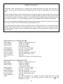
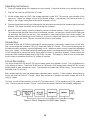
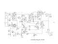
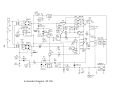
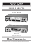
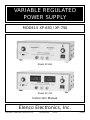
VARIABLE REGULATED
POWER SUPPLY
MODELS XP-650 / XP-750
Model XP-650
Model XP-750
Instruction Manual
Elenco Electronics, Inc.
Copyright © 1989 Elenco Electronics, Inc.
Revised 1998
REV-D
753650
Table of Contents
Safety Precautions
Specifications
Operating Instructions
Introduction
Circuit Description
Power Source
0-20V or 0-40V Regulators
XP-750 Digital Meters
Maintenance and Calibration
Variable 0-20VDC Regulator Calibration
Variable 0-40VDC Regulator Calibration
Digital Meter Calibration on Model XP-750
Parts List XP-650
Parts List XP-750
Schematic Diagram XP-650
Schematic Diagram XP-750
-1-
Page
Page
Page
Page
Page
Page
Page
Page
Page
Page
Page
Page
Page
Page
Page
Page
2
2
3
3
3
4
4
5
6
6
6
6
7
8
9
10
Safety Precautions
CAUTION: When removing cover or replacing fuse, always disconnect the power cord from the AC
socket. Service repair should be done by qualified personnel who are knowledgeable of electrical hazards.
Certain safety precautions must be observed when this power supply is used with external circuits that
are connected to AC power lines. There is always some danger when working with electrical equipment
or circuits that operate at hazardous voltages. You should thoroughly familiarize yourself with the equipment before working on it. High voltage may appear at unexpected points in defective equipment.
Elenco power supplies are equipped with three wire line cords which ground the chassis to the power
line cord. DO NOT CUT OFF OR DISABLE THE GROUND PLUG.
The power supply secondary circuits are isolated from the 120V primary circuit via the power transformer. When working with the other equipment, this may not always be the case. Always be familiar
with the equipment rating. Keep in mind that defective equipment can have dangerous voltages at unexpected points.
Specifications for Model XP-650
Input Voltage
Output Voltage
Output Current
Load Regulation
Line Regulation
Ripple and Noise
Current Protection
Short Protection
Output Impedance
Meter
120VAC or 240VAC (factory set)
0-20VDC or 0-40VDC
3 Amps @ 0-20VDC
1.5 Amps @ 0-40VDC
Less than .1V (0 to full load)
Less than .1V (105 to 135V)
Less than .005V RMS
.05 to 3A adjustable current limit
.05 to 3A limit automatic reset
.025 ohms
40 Volts and 3 Amps, 5% full scale accuracy
Specifications for Model XP-750
Input Voltage
Output Voltage
Output Current
Load Regulation
Line Regulation
Ripple and Noise
Current Protection
Short Protection
Output Impedance
Meters
120VAC or 240VAC (factory set)
0-20VDC to 0-40VDC
3 Amps @ 0-20VDC
1.5 Amps @ 0-40VDC
Less than .1V (0 to full load)
Less than .1V (105 to 135V)
Less than .005V RMS
.05 to 3A adjustable current limit
.05 to 3A limit automatic reset
.025 ohms
Two LED type meters. The voltmeter accuracy is better than 1/2% +1 digit.
Resolution is 100mV. The ammeter accuracy is better than 1% +1 digit.
Resolution is 10mA.
-2-
Operating Instructions
1. Check the voltage rating of the equipment to be powered. Care must be taken not to exceed this rating.
2. Plug the line cord into a 120V 60Hz AC outlet.
3. Set the voltage switch to 0-20V if the voltage required is under 20V. This assures cool operation of the
heat sinks. Adjust the voltage control to the desired voltage. Load variation will have practically no
effect on the voltage setting due to the special regulation circuit.
4. Connect the positive lead of your equipment to the red output terminal and the negative lead to the black
terminal. The power should be turned off during this operation.
5. Adjust the current limiting control to maximum counter-clockwise position. Switch your equipment on.
The overload light will glow if more than 50 milliamps is drawn. Increase this control until the light goes
out and stays out during normal use. Your equipment is now protected from high current surges. An
alternate method of adjusting current limiting is to short the output and adjust the current to a desired
value. Remove the short. This will now limit the current to your setting.
Introduction
The Model XP-650 and XP-750 are solid-state DC power supplies, continuously variable from 0 to 40 volts.
Two current ranges are available, 0-20V @ 3 amps and 0-40V @ 1.5 amps. The units are precisely held to
the desired output voltage by a special regulating circuit. Maximum output current is externally adjustable
from .05 to 3 amps. An overload indicating lamps glows when current approaches limiting conditions. This
circuit is designed to protect the power supply against shorts or excessive demand. It also protects the
equipment from possible damage due to high surge currents. This supply is ideal for use in school labs,
service shops or anywhere a precise DC voltage is required.
Circuit Description
The Elenco Models XP-650 and XP-750 use the same power and regulator circuits. The only difference is
in the display functions. The Model XP-650 uses a 0-40V and a 0-3A analog meter. Model XP-750 has two
digital meters to read voltage and current. The voltmeter has better than 1/2% accuracy. The current meter
has better than 1% accuracy.
Both models basically have two independent regulated power supplies. These supplies, when placed in
series, will give 0-40 volts @ 1.5 amps. When they are placed in parallel, the output voltage will be 0-20
volts @ 3 amps.
The basic circuits of these supplies consist of 1) The power source, 2) The regulator and 3) The readout circuits. These circuits are shown in Figure 1 and will be discussed in detail in the following paragraphs.
Figure 1 Block Diagram of 0-20V Power Supply
-3
3-
Power Source
The power source in both the XP-650 and XP-750 consists of two transformers T1 and T2 and two diode
bridges, D1 to D4 and D5 to D8. C3 and C5 are the filter capacitors. Switch S2 places these supplies in
series to produce about 50VDC output or in parallel to produce about 25VDC out.
A negative 25 volts is produced with diodes D9, D10 and capacitors C1 and C2. This negative voltage is
regulated with zener diodes D11 and D15. The negative voltage is needed to stablilize the regulators and
allow zero output voltage.
Figure 2 Simplified Regulator Circuit
0-20V or 0-40V Regulators
Figure 2 shows a simplified circuit of the regulator circuit. This circuit consists of a high gain amplifier transistor Q1. The gain of this stage is over 100,000 because of its extremely high load impedance. This load
consists of a current source transistor Q2 and its biasing circuit. The effective resistance of this circuit is
over 500,000 ohms. Transistor Q7 is a power device that controls the output current. Transistors Q5 and
Q6 are emitter followers used to prevent loading of the current source. Transistors Q1, Q5, Q6, Q7 and
resistors R10 and VR4 form a closed negative feedback loop. If you analyze this loop, you will find that the
output voltage goes negative. This reduces the current in transistor Q1 and thus the collector voltage will
increase, returning the output voltage to very near its original value. The high gain is essential to keep the
output voltage constant. Diode D12 is added to prevent drift with temperature changes and to allow the
output voltage to go to zero.
To protect the regulator from overload and short circuit, transistor Q4 is added. Whenever the voltage drops
across resistor R10 reaches .6V, transistors Q4 and Q9 will conduct and lower the collector voltage of amplifier Q1. To obtain variable current limiting, transistor Q4 is pre-biased via resistor R5 and VR3. This will
allow the output current to limit between .05 and 3 amps. Transistor Q3 is added to light the overload LED.
Switch S2C sets the maximum output voltage to 0-20 or 0-40VDC by adjusting variable resistors VR1 or VR2.
Maximum current limiting is set by switch S2D. Resistors R10 and R11 are used to limit the 0-40V current
to 1.5 amps. When resistors R12 and R13 are added to the circuit, the maximum current is increased to 3
amps.
-4-
XP-750 Digital Meters
The Model XP-750 uses two digital meters, one for output voltage and one for output current. The input to
the voltmeter comes from a 1000:1 voltage divider, R101 and R102 on the power supply output. Thus, the
voltmeter input will be 1mV for a 1V output voltage. Since the meter sensitivity is 10 counts per mV, the
meter will read 010. The decimal point is fixed by a jumper wire on the meter so that the output appears as
01.0 volts.
The ammeter input comes from a .01 ohm shunt resistor in series with the output current. The input is thus
10mV (100 counts) for a 1A output current. The ammeter decimal point is set to the 2nd place so that the
meter reads 1.00 amps.
Meter Operation
METERS - Meter operation centers around the 7107 integrated circuit (IC). This chip contains a dual slope
A/D (analog to digital) converter, display latches, seven segment decoder, and display drivers.
The input of the 7107 IC is fed to an A/D converter. Here, the DC voltage is changed to a digital format. The
resulting signals are processed in the decoders to light the appropriate LED segments.
Timing for the overall operation of the A/D converter is derived from a 40kHz external oscillator. The IC
divides this frequency by four and the resulting clock pulses are used to drive its decade counters. It is
then further divided to form three convert-cycle phases. The final readout is clocked at about 2.5 readings
per second.
The digitized data is presented to the display as four decoded digits (seven segments) plus polarity. The
decimal point position on the display is determined by a jumper wire on each meter PC board.
A/D CONVERTER - Any given measurement cycle performed by the A/D converter can be divided into three
consecutive time periods, autozero (AZ), integrate (INTEG) and read. A counter determines the length of
the time periods. The integrate period is fixed at 1000 clock pulses. The read period is a variable time that
is proportional to the unknown input voltage. It can vary from zero counts for zero input voltage to 2,000
counts for a full scale input voltage. The autozero period varies from 1,000 to 3,000 counts. For an input
voltage less than full scale autozero gets the unused portion of the read period.
During the autozero cycle, the accumulated offset voltage errors in the converter are measured and stored
as a voltage on the external autozero capacitor. This voltage is used to correct for the offset voltage errors
during the read cycle.
During the INTEG cycle, the INTEG capacitor is charged up for 1,000 clock pulses (100ms.), see Figure 3.
The charging rate is determined by the unknown input voltage. At the end of the integrate cycle the voltage on the capacitor is proportional to the unknown input voltage.
During the read cycle, the INTEG capacitor is discharged at a constant rate. The time required for the discharge is therefore proportional to the unknown input voltage. This time is converted to a digital format by
counting the number of clock pulses that occur during the discharge.
Counter Output
Figure 3 Dual Slope A/D Converter
-5-
Maintenance and Calibration
The Elenco Models XP-650 and XP-750 have been designed and manufactured to require no routine maintenance. The circuits are protected by design from external shorts or overloads. The following information
is provided in the event the supply requires service or re-calibration.
Variable 0-20VDC Regulator Calibration
1) Connect an accurate digital meter to the output terminals.
2) Set the voltage control to the maximum position and switch to 0-20V.
3) Adjust the variable resistor VR1 for 20.0V.
Variable 0-40VDC Regulator Calibration
1) Connect an accurate digital meter to the output terminals.
2) Set the voltage pot to maximum position and voltage switch to 0-40V position.
3) Adjust the variable resistor VR2 for 40.0V.
Digital Meter Calibration for Model XP-750
1) Note the small pot (R2) on the top of each meter’s PC board. This is the GAIN pot which controls the
accuracy of the meter.
2) To set the accuracy of the meter you need another very accurate digital meter. Connect this meter to
measure the voltage on the output terminals. Set the voltage switch to 0-40V position and set the output to 30VDC. Adjust the voltmeter GAIN pot for 30.0 volts on the XP-750 meter.
3) To set the accuracy of the ammeter connect a suitable load to the output and connect the accurate digital meter to measure the current on the load. Set the voltage switch to 0-20V and set the output current to 2.0 amps. Adjust the ammeter GAIN pot for 2.00 amps on the XP-750 ammeter.
-6-
Parts List XP-650
Qty
Description
Resistors
Part #
Qty
106803
122200
132000
132201
133300
134700
141000
141001
141200
141800
144700
153900
161000
191516
192413
192511
!
!
!
!
!
!
!
!
!
!
!
!
!
!
!
!
!
!
!
!
!
!
!
!
!
!
!
!
!
!
!
!
!
!
!
!
!
!
!
!
!
!
!
!
!
!
!
!
!
!
!
!
!
!
4
1
1
1
1
2
2
1
1
1
1
1
1
2
1
1
.68Ω 5% 2W
22Ω 5% 1/4W
200Ω 5% 1/4W
220Ω 5% 1/2W
330Ω 5% 1/4W
470Ω 5% 1/4W
1KΩ 5% 1/4W
1KΩ 5% 1/2W
1.2KΩ 5% 1/4W
1.8KΩ 5% 1/4W
4.7KΩ 5% 1/4W
39KΩ 5% 1/4W
100KΩ 5% 1/4W
Pot 10KΩ Trim
Pot 1KΩ Panel
Pot 10KΩ Panel
!
!
!
!
!
!
!
1
1
1
1
1
1
2
.001µF (102)
.1µF (104) 25V
Lytic 10µF 50V
Lytic 100µF 35V
Lytic 160µF 330V
Lytic 470µF 35V
Lytic 3300µF 50V
!
!
!
!
!
!
5
2
1
1
8
1
1N4001
1N4148
1N5240
1N5246
1N5401
LED
!
!
!
!
2
2
4
1
A70
2N3055
MPS 5172
2N6121
Capacitors
231036
251010
271057
281046
281629
284746
293347
Diodes
314001
314148
315240
315246
315401
350002
Transistors
320070
323055
325172
326121
-7-
2
1
1
1
1
1
1
1
1
1
2
2
1
3
1
1
1
1
2
2
1
1
1
4
12
2
4
5
2
2
5
4
4
1
2
4
1
1
Description
Miscellaneous
Transformer
PC Board
Fuse 2A
Switch Slide
Switch Illuminated
Voltmeter 40V
Ampmeter 0-3A
Cover
Chassis
Meter Bracket
Heatsink
Knob
Bushing Strain
PC Board Stand-off
Binding Post Black
Binding Post Red
Binding Post Green
LED Lens
Cable Tie
Screw 4-40 x 1/4”
Screw 4-40 x 3/8”
Screw 4-40 x 3/4”
Screw 8-32 x 1/4”
Screw 8-32 x 3/8”
Screw 6 x 3/8”
Nut Hex Pot
Nut 4-40
Nut 8-32
Flatwasher 8mm x 14mm
Flatwasher 1/8” x 1/4”
Lockwasher 5/16”
Lockwasher #4 internal
Lockwasher #8 external
Lug Solder #8
Butt Connector
Feet Rubber
Fuse Holder
Line Cord
Part #
440400
510650
530200
541190
541204
571040
573003
611071
611650
613015
615001S
622009
624003
625002
625031
625032
625033
626012
628982
641430
641435
641480
641830
641840
642660
644101
644400
644800
645101
645600
646101
646401
646828
661002
661100
662001
663001
862105
Parts List XP-750
Qty
Description
Resistors
Part #
Qty
106803
122200
125005
132000
132201
133300
134700
141000
141001
141200
141800
141801
144700
153900
161000
171000
191516
192413
192511
897120
!
!
!
!
!
!
!
!
!
!
!
!
!
!
!
!
!
!
!
!
!
!
!
!
!
!
!
!
!
!
!
!
!
!
!
!
!
!
!
!
!
!
!
!
!
!
!
!
!
!
!
!
!
!
!
!
!
4
1
1
1
1
1
2
3
1
1
1
1
1
1
1
1
2
1
1
1
.68Ω 5% 2W
22Ω 5% 1/4W
50Ω 10% 5W
200Ω 5% 1/4W
220Ω 5% 1/2W
330Ω 5% 1/4W
470Ω 5% 1/4W
1KΩ 5% 1/4W
1KΩ 5% 1/2W
1.2KΩ 5% 1/4W
1.8KΩ 5% 1/4W
1.8KΩ 5% 1/2W
4.7KΩ 5% 1/4W
39KΩ 5% 1/4W
100KΩ 5% 1/4W
1MΩ 5% 1/4W
Pot 10KΩ Trim
Pot 1KΩ Panel
Pot 10KΩ Panel
Shunt Wire .01Ω
!
!
!
!
!
!
!
!
!
1
1
1
1
1
1
1
1
2
.001µF (102)
.1µF (104) 25V
Lytic 4.7µF 50V
Lytic 10µF 50V
Lytic 100µF 35V
Lytic 160µF 300V
Lytic 220µF 35V
Lytic 470µF 25V
Lytic 3300µF 35V
!
!
!
!
!
!
5
2
1
1
8
1
1N4001
1N4148
1N5240
1N5246
1N5401
LED
!
!
!
!
2
2
4
1
A70
2N3055
MPS 5172
2N6121
Capacitors
231036
251010
264757
271057
281046
281629
282246
284745
293347
Diodes
314001
314148
315240
315246
315401
350002
Transistors
320070
323055
325172
326121
Integrated Circuits
-8-
1
1
2
1
1
1
1
1
1
1
1
2
1
3
1
1
1
1
1
1
2
1
4
12
2
3
5
2
2
4
3
5
1
2
4
1
1
Description
Miscellaneous
Display Amps
Display Voltage
Transformer
PC Board
Fuse 2A
Switch Slide
Switch Illuminated
Cover
Chassis
Heatsink
Heatsink Clip-on
Knob
Bushing Strain
PC Board Stand-off
Binding Post Black
Binding Post Red
Binding Post Green
LED Lens
Screw 2-56 x 3/4”
Screw 4-40 x 3/8”
Screw 4-40 x 1/2”
Screw 8-32 x 1/4”
Screw 8-32 x 3/8”
Screw 6 x 3/8”
Pot Nut 7mm
Nut 4-40
Nut 8-32
Flat Washer 8mm x 14mm
Lockwasher 5/16” internal
Lockwasher #2 Internal
Lockwasher #4 internal
Lockwasher #8 external
Lug Solder #8
Butt Connector
Feet Rubber
Fuse Holder
Line Cord
Part #
355614MA
355614MV
440400
510650
530200
541190
541204
611071
611750
615001S
615003
622009
624003
625002
625005
625006
625007
626012
641233
641435
641465
641830
641840
642660
644101
644400
644800
645101
646101
646200
646401
646828
661002
661100
662001
663001
862105
160µF
330V
-9-
50V
50V
Schematic Diagram XP-650
160µF
330V
50V
-1050V
Schematic Diagram XP-750
WARRANTY POLICY
All of our instruments have been tested and conform to our rigid requirements on
performance and durability, they are guaranteed to be free of defects in workmanship, materials and construction for a period of 2 years. If this product should
fail in normal use within the first 3 months from the date of purchase, Elenco will
repair or replace the unit at no cost. For the remainder of the warranty period, a
nominal service charge is required to cover shipping and handling. Elenco will
either repair or at its sole option, replace any part except for fuses, probes, lamps,
batteries and other optional materials which are defective in either workmanship
or material under normal and proper use.
When returning merchandise for repair, please include proof of purchase, a brief
letter of explanation of problem and sufficient packing material. Before returning
any merchandise, please call our service department at 847-541-3800 to obtain a
return authorization number (RMA).
Direct all warranty inquiries to:
Elenco Electronics, Inc. • Service Department
150 West Carpenter Avenue, Wheeling, IL 60090 • Phone: (847) 541-3800
Elenco Electronics, Inc.
150 W. Carpenter Avenue
Wheeling, IL 60090
(847) 541-3800
http://www.elenco.com
e-mail: [email protected]