1
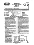
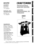
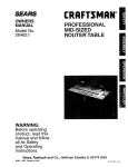
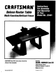
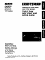
OWNERS
MANUAL
Model No.
171.240300
Attaches to most table
saw miter gauges.
TABLE SAW
BOX JOINT AND
MITER GUIDE
WARNING:
Before operating
product, read this
manual and follow
all its Safety
and Operating
Instructions.
Sears,
171.240300
05/98
Roebuck and Co.. Hoffman
Printed in U.S.A.
Estates IL 60179 USA
General Safety Instructions
Additional Safety Instructions
for Power Tools ...............................
:.. ............ 3
for Box Joint Templates ............................ 4
Optional Table Saw Accessories ..................................................................
5
Unpacking and Checking Contents .............................................................
5
Assembly ........................................................................................................
6
Operation ........................................................................................................
9
Helpful Hints ........................................................................................................
15
Parts List ..............................................................................................................
17
2
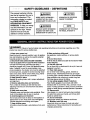
This manual contains information that is important for you to
know and understand. This
information relates to protecting YOUR SAFETY and
PREVENTING EQUIPMENT
PROBLEM. To help you recognize this information, we use
symbols to the right. Please
read the manual and pay
attention to these sections.
IADANGER
I
[- CAUT,O.]
URGENT SAFETY INFORMATION -
INFORMATION FOR pREVENTING
A HAZARD THAT WILL CAUSE
DAMAGE TO EQUIPMENT
SERIOUS INJURY OR LOSS OF LIFE
IAWARNING I
I
IMPORTANT SAFETY INFORMATION -
INFORMATION
A HAZARD THAT M/G/'/T CAUSE
PAY SPECIAL
NOTE
I
_HAT YOU SHOULD
ATrENT_ON
TO
SERIOUS INJURY OR LOSS OF UFE
IA
I
I AwARNING
] Failure to heed all safety and operating instructions and warnings regarding use of this
product can result in serious bodily injury.
1. Know your power tool
Read the owner's manual carefully. Learn its application and limitations as well as the specific potential
hazards peculiar to this tool.
2. Ground all tools (unless double Insulated)
If tool is equipped with an approved three-conductor
cord and a throe-prong grounding type plug, it
should be plugged into a throe hole electrical receptacle. If adapter is used to accommodate a twoprong receptacle, the adapter wire must be attached
to known ground, (usually the screw securing receptacle cover plate). Never remove third prong. Never
connect green ground wire to_a terminal.
3. Keep guards In place
Maintain in working order, and in proper adjustment
and alignment.
4. Remove adjusting keys and wrenches
Form a habit of checking to see that keys and
adjusting wrenches are removed from tool before
turning it on.
5. Keep work area clean
Cluttered areas and benches invite accidents. Floor
must not be slippery due to wax or sawdust.
6. Avoid dangerous environment
Do not use power tools in damp or wet locations or
expose them to rain. Keep work area well lighted.
Provide adequate surrounding work space.
7. Keep children away
All visitors should be kept a safe distance from work
area.
8. Make workshop child-proof
Use padlocks, master switches, or remove starter
keys.
9. Do not force tools
It will do the job better and safer at the rata for which
it was designed.
10. Use the right tool
Do not force tool or attachment to do a job it was not
designed to perform.
11. Wear right apparel
Do not wear loose clothing, gloves, neckties or
jewelry (rings, wristwatches) that may get caught
in moving parts. Nonslip footwear is recommended.
Wear protective hair covering to contain long hair.
Roll long sleeves above the elbow.
12. Use safety goggles (Head Protection)
Wear Safety goggles (must comply with ANSi
Standard Z87.1 ) at all times. Also, use face or dust
mask, if cutting operation is dusty, and ear protectors
(plugs or muffs) during extended periods of operation.
13. Secure work
Use clamps or a vise to hold work when practical.
It's safer than using your hands, and it frees both
hands to operate tool.
14. Do not overreach
Keep proper footing and balance at all times.
15. Maintain tools with care
Keep tools sharp and clean for best and safest
performance. Follow instructions for lubricating and
changing accessories.
16. Dlecortnect tools ....
21. Direction of feed
Before servicing, when.chan_] n_j"a_ries
such ,'- _
as blades, bits, cutters, etc.
17. Avoid accidental starting
Make sure switch is in "OFF" position before
plugging in.
lB. Use recommended accessories
Consult the owner's manual for recommended
accessories and follow the instructions. The use of
Feed W0rk ,into a bl_db!0r cuttbr only against the
direction of rotation of the blade or cutter.
22. Never leave tool running unattended
Turn power off. Do not leave tool until it comes to a
complete stop.
23. Keep hands away from cutting area
24. Store idle tools
When not in use, tools should be stored in dry, high
or locked-up place - out of reach of.children.
25. Do not abuse cord
improper accessories may cause hazards.
19. Never stand on tool
Serious injury could occur if the tool is tipped or
if the cutting tool is accidentally contacted. Do not
store materials above or near the tool making it
necessary to stand on the tool to reach them.
20. Check damaged parts
Before further use of the tool, any guard or other part
that is damaged should be carefully checked to
ensure that it will operate properly and perform its
intended function. Check for alignment of moving
parts, binding of moving parts, breakage of parts,
mounting, and any other conditions that may affect
its operation. A guard or any other part that is damaged should be properly repaired or replaced.
Keep cord away from heat, oil and sharp edges.
26. Outdoor extension cords
When tool is used outdoors, use only extension
cords suitable for use outdoors and so marked.
27. Never use in an explosive atmosphere
Normal sparking of the motor couldignite fumes,
flammable liquids, or combustible items.
28. Drugs, alcohol, medication
:
Do not operate tool while under the influence of
drugs, alcohol, or any medication.
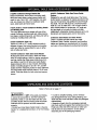
Read and Understand this instruction book
completely BEFORE using this product.
1. Always wear eye protection that complies with
current ANSI Standard Z87.1.
ILJmWARNING
I Always UNPLUG the table saw
from the electrical outlet:
2. Noise levels vary widely. To avoid possible hearing damage, wear ear plugs or muffs when using the
Table Saw Box Joint and Miter Guide.
3. Wear a dust mask along with the safety goggles.
4. Follow the instructions in your table saw owner's
manual.
• before installing or removing saw blades from the
table saw
• when adjusting the cutting depth or width of the
saw blade or dado blade
• when changing the setup of the Box Joint and
miter guide.
8. Making box joint cuts requires the unit to pass
over the saw blade. Remember to keep your hands
away from the cutting area.
9. When setting up to make test cuts using the box
joint unit, confirm that the saw blade or dado blade
does not contact the fixture.
5. Do not use this product until all assembly installation steps have been completed, and you have read
and understand all safety and operational instructions in this manual.
6. This product is designed to cut flat workpieces.
Do not out or attempt to cut workpieces that are
. not flat or that are irregularly shaped.
7. This product is to be used for cutting wood workpieces only. Do not use this product to cut metal.
10. Confirm that all fasteners remain tight and
secure through all operations:
4
9-32040CraftsmanStorageBasketSet
Keepsaccessories,
fence(whennotbeingused),
tablesawinsartplates,projectpieceshandyand
readyforuse.Two8 3/4"x 36"baskets; one open
end, one closed and. Mount to Craftsman table
saws, radial saws and band saws.
9-3214, 9-3217, 9-3218 Craftsman Molding Heads
and Molding Sets
Turn your table saw into a shaper with one of the
unique Craftsman molding head sets. Make decorative edges, woodworking joints, and fan_y trim with a
Craftsman molding head cutter bits.
9-3233 Craftsman Taper Jig
Tapers to 3 in/ft or 15% Handy reference scale in
degrees of taper. Has locking bracket and positive
push heal. May be reassembled for use on either
side of table saw fence.
9-32371 Craftsman Table Sew Fence Guide
System
Designed for use with most table saws. The Fence
Guide System is designed for ripping operations sliding over the rip fence and guiding the stock through
the blade. The unit will adjust to a maximum fence
width of 2 1/2" in width and 3 1/8" in height. Built-in
setup checks blade for squareness, 45 ° angle setting and depth of cut scale for blade and dado
height/depth. Adjustable clamping features aid in cutting tenons and sawing spine cut for miter joints.
Craftsman Saw Blades and Dado Heads
There is a blade and dado almost any need.
Craftsman Steel, Carbide, Industrial, and Excalibur
blades and dadoes are manufactured for the weekend user or the professional woodworker/contractor.
9-32190 Craftsman Table Saw Guide Master
Multipurpose push shoe helps in table saw blade
setup for angle settings. Used for ripping operations;
has high handle that helps keep hands away from
saw blade. Long front of table saw Guide Master
keeps pressure down on top of board, eliminating
chatter. Includes gauges for 22 1/2° , 45 °, and 90 °
angles and two measuring scales for easy reference.
Accurate blade height indicator steps in 1/16" increments. Finds the center for both round and square
pieces.
Refer to Parts List on page 17
[__WARNINGJ
If ANY of the parts are missing,
or cannot be accounted for, DO NOT attempt to
assemble, install, or use the Table Saw Box Joint
and Miter Guide until the missing parts have been
obtained and the product has been assembled
properly.
- Contact your local Sears Retail Outletl or Service
Center, for a replacement product, or for the missing
pads.
• In order to simplify handling, and to minimize
any damage that may occur during shipping, your
Table Saw Box Joint and Miter Guide are packaged
unassembled.
• Separate all parts from the packaging materials
and check each part against the illustrations and the
Parts List at the end of this manual, to make sure
that all parts are accounted for. Do this before
discarding any of the packaging material.
TOOLSlNCLUDED
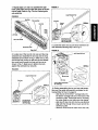
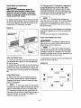
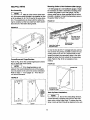
4. Assemble the left slide piece to the left lower
guide as shown in Fig. 3.
• Mini-driver, 3/8" nut driver and P2 Phillips insert bit
FIGURE 3
SEE PARTS LIST FOR EXPLODED VIEW OF
TABLE SAW BOX JOINT AND MITER GUIDE
#10 Flex Nut
#10 Washer
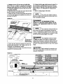
1. Carefully unpack components from carton and
confirm that all parts have been shipped with the
product (refer to the parts list on page 15 of instruction manual to identify the components).
2. Locate the main guide and slide four (4) of the
#10xl 3/8" carriage bolts into the carriage bolt slot
and space apart as shown in Fig. 1.
Left Slide
#10 Hex Nut
#10Washer
Aluminum Guide
FIGURE 1
7
I
#10 x 1 - 3/8" Carriage Bolt
Product/Warning
Label
3. Place the left lower guide over two (2) of the carriage bolts as shown in Fig. 2. Confirm that the hash
marks on the lower left guide and the product/warning label are facing in the same direction as shown
in Fig. 2.
/
J
Left Lower Guide
5. Install the #10 washers and hex nuts on the two
carriage bolts making sure to thread the hex nuts so
the left lower guide and the left slide piece can be
adjusted side-to-side during the assembly steps.
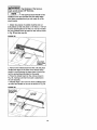
6. Attach the fixed tab and adjustable tab to the right
slide piece using the #10 hex nut and the #10x3/8"
pan head screw. Refer to Fig. 4 for the correct orientation of the tabs and for the placement of the hex
nut.
FIGURE4
FIGURE2
JlO x 1 - 3/8" Carriage
BoR
Right Sllde
Aluminum
Guide
Drop Hex Nut
Into Slot
Fixed Tab
Left Lower Guide
AdJustobleTab
_nH_d
_rew
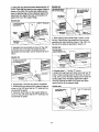
FIGURE 7
7. Repeat_steps 3; 4and 5 to assemble the right
lower guidltpiece and the right slide piece to the alu=
minum guide. Refer to Fig. 5 for the finished guide
sub-assembly.
Long Extension Bar
FIGURE 5
Hex Nuts
Tab Assembly
End Cap
DETAIL A
Round
Knob
Hex Nuts
Left Slide
Slide Hex Nut into
Hex Nut Slot, Align
with Through Hole
Left Lower Guide
Aluminum
9. Locate the other end cap and short extension bar
and assemble following step 8 and Fig. 8.
Guide
FIGURE 8
Right Slide
8. Locate one of the two (2) end caps and the long
extension bar. Assemble the end cap and the long
extension bar as shown in Fig. 6. Slide one (1) hex
nut into the hex nut slot on the end cap and thread
the round knob through the hole and hex nut as
shown in Fig. 7. Make sure to tighten the knob
against the extension bar securely.
Short Extension
Bar
FIGURE 6
Long Extension
Bar
End Cap
.:..,.,E.:,.=
Ex=...
F
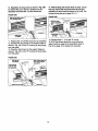
10. Before assembling the two end cap sub-assemblies and the guide sub-assembly complete the following (Refer to Fig. 9 on page 8):
- slide two (2) of the #10x1" carriage bolts into
the bottom carriage bolt slot on the back of the
aluminum guide. These bolts are for mounting
the miter guide to your table saw miter gauge.
- slide two (2) hex nuts into the hex nutslot and
align with the through hole on each end of the
aluminum guide.
- thread a round knob into each of the hex nuts.
\
\
Extension Bar
LineUpE_
of _
with This Edge
0
7
FIGURE
9
12. Slide the long extension bar sub-assembly into
the.aluminum guide as shown in Fig. 11. Slide the..._
bar intothe extrusion
until
theend cap isincontact
withthealuminum guideend,
i
I
i
NOTE
I The end caps and extensionbars
are interchangeable
ineitherend ofthe miterbarfor
use on eithersideofsaw blade.Reorienting
exten-.
sion bar and end caps will be necessary.
13. Repeat step 12 for the short extension bar.
14. Attach the guide to your miter gauge using the
two carriage bolts on the back of the aluminum
guide, two (2) #10 washers, and two (2) three wing
knobs as shown in Fig. 12.
Slide HeX Nut Into
Hex Nut Slot Align
with Through Hole
FIGURE 12-
Bottom Carriage
Bolt Slot
#10 x 1" Carriage Bolts
In Cardage Bolt Slot
Round
Knobs
i
-
11. Slide one (1) #10xl" carriage bolt into the top
carriage bolt slot on the front of the aluminum guide
and install the stop piece, #10 washer, and three
wing knob as shown in Fig. 10.
FIGURE 10
Aluminum
Guide
Top Front Carriage
Bolt Slot
Three Wine
Knobs
lashers
#10 Washer
Bottom Carriage
Bolt Slot
Parts Removed from
Miter Gauge for Clarity
15. The miter guide should now be fully assembled
and be ready for use on your table saw. Refer to Fig.
13 for a fully assembled view.
Three Wing
Stop Piece
FIGURE 13
Hex Nut Slot
BLADE GUARD NOT SHOWN FOR CLARITY
FIGURE 11
Stop place
Aluminum
Extension
Guide
lyp. Table Saw Top
(Extensions NOt
Shown For Clarity)
Bar
8
MITER FENCE
I
FIGURE 15
USE TIPS
BLADE GUARD NOT SHOWN FOR CLARITY
I
NOTE
Typ. Table Saw Top
(Extensions Not Shown For Clarity)
I If your table saw is not a
Craftsman stationary saw, it may be necessary to attach a secondary mounting piece to the miter gauge
in order to'mount the miter guide. REFER TO PAGE
15 FOR SPECIAL MOUNTING INFORMATION.
DIRECTION
OF FEED
Common Uses:
The unit can be used for the following crosscutting
operations:
- 90 degree crosscuts
- Miter cuts using the miter gauge
- Compound miter cuts
- Repeatable length crosscuts up to 36"
l
I -_ cAUTION I When using the miter guide to
make crosscut, confirm that the unit does not interfere with the blade guard. When using the left miter
slot, adjust the guide so that the end cap can pass by
the blade guard. IT IS NOT RECOMMENDED THAT
THE GUIDE RAISE THE BLADE GUARD DURING
THE CUTTING OPERATION. Refer to Fig. 14.
FIGURE 14
BLADE GUARD NOT SHOWN FOR CLARITY
ROTATION
Repeatable Length Crosscut:
1. When using the miter guide for this operation,
adjust the stop piece to obtain the desired workpiece
length. Refer to Fig. 16.
IAWARNINGI
Ensure
that the three wing knob
on stop piece and two (2) three wing knobs on miter
gauge are tight and secure to prevent movement of
stop piece and miter guide.
FIGURE 16
//
BLADE GUARD NOT SHOWN FOR CLARITY
Stop Piece
J
J
NOTE: Check That
Guide Does Not
Contact Blade Guard
I_,II._CAUTIONI
DIRECTION
OF FEED
Typ. Table Saw Top
{Extensions Not Shown For Clarity)
WHEN USING THE RIGHT MITER
SLOT, THE END CAP AND EXTENSION BAR MAY
HAVE TO BE REMOVED TO CLEAR THE BLADE
GUARD. IT IS NOT RECOMMENDED THAT THE
GUIDE RAISE THE BLADE GUARD DURING THE
CUTTING OPERATION. Refer to Fig, 15.
NOTE: Check That
Guide Does Not
Contact Blade Guard
Typ. Table Saw Top
(Extensions Not Shown For Clarity)
2. if the cut length is over 18,, move the stop piece - Conversion from Miter Guide Setup to Box Joint
ont_:[he end cap and adjust the extension bar to the . Setup:
_
" ,
::_ _
"
proper length. Refer to Fig. 17.
1. Remove the stop piece assembly, the right end
cap and the extension bar that is assembled to the
FIGURE 17
right end cap. Tighten the round knob that held the
BLADE GUARD NOT SHOWN FOR CLARITY
extension bar until the knob is secure against the
aluminum guide. Refer to Fig. 18.
/
DIRECTION
OF FEED
FIGURE 18
End Cap
TIghten Knob Against
Aluminum Guide
Stop Piece
NOTE: Check That
Guide Does Not
Contact Blade Guard
I
Typ. Table Saw Top
(Extensions Not Shown For Clarity)
I
NOTE
I If the cut length is longer than 36",
the miter guide can still be used to guide the wood;
however, the stop piece must be removed from the
miter guide.
BOX JOINT SYSTEM
2. Flip the miter guide over and loosen the four hex
nuts on the dght and left slide pieces. Slide the right
and left side pieces forward to form a support ledge.
Refer to Fig. 19.
3. Slide the right lower guide and right slide assembly away from the left guide assembly to form a
large gap between the pieces. Refer to Fig. 19.
USE TIPS
Using this unit enables you to make box joints that
can be any width from 1/8" up to 13/16" wide. For
purpose of the manual, it is assumed that a dado
blade set will be used to cut the sockets (female portion of the joint).
I
FIGURE 19
i
Hex
Nuts
I
NOTE
I Before starting the following setup
steps, determine the width of the fingers/sockets on
the box joint for the project.
Slide Forward to
Form Support Ledge
Table Saw Setup:
I
NOTE
, He]( Nuts
I
I Before converting the unit from the
Miter Guide setup to the Box Joint setup, the table
saw and dado need to be prepared for the box joint
cutting operation. The following steps assume that
the miter gauge is already attached to the unit. If the
gauge is not attached to the unit, refer to page 8,
step 14 for proper miter gauge installation.
SIIde Ootto
Form Gap
Gap BetweenLeftand
Right Lower GuldePleces
I_WARNINGI
Before
pertorming
anyofthefollowing
setup steps UNPLUG the table saw from the
electrical outlet.
1. Referring to the table saw owner's manual,
remove the blade guard and spreader.
2. Install the dado on the saw, setup the cutting
width, and install the proper table insert for dadoing.
10
I
NOTE
I This gap will allow the unit to pass
over the dado dudng the box joint cutting operations.
The gap width needs to be approximately 3 TIMES
the width of the dado. Refer to Fig. 21, °E"
Dimension for exact dimension details.
4. Retighten the two (2) hex nuts on the left slide
piece. There is no mason to mposltion the left guide
assembly While using the unit in the Box Joint Setup.
5. Temporadly retighten the two (2) hex nuts on the
right guide assembly.
6. Place the unit on the table saw such that the miter
gauge is located in the left miter slot.
7. Loosen the two (2) three wing knobs that hold the
unit to the miter gauge and reposition the entire unit
as shown in Fig. 20.
10. Confirm that the gap, which was set in step 3, is
set correctly by measuring from the end of the aluminum guide to the end of the right guide assembly.
Refer to Fig. 21, "E" Dimension for measurement
details.
11. Set the cutting height of the dado.
NOTE
] The unit is now ready to make a
test cut to check that the previous setup steps have
been completed correctly.
FIGURE 20
IAIlmWARNINGITHE MAXIMUM CUTTING
HEIGHT OF THE DADO WHEN USING THE FIXTURE IS 1 1/8" (MEASURED FROM THE TABLE
SAW TOP).
I
NOTE
I The maximum socket (female por-
tion of the joint) depth and workpiece thickness is
13/16". To determine the depth that the dado will cut
a socket, subtract the thickness of the support ledge
(5/16") from the cutting height of the dado.
IAII=AWARNING
I The workpiece must be at least
ROTATION
6 TIMES the width of one finger or socket and be
supported at all times to avoid any tipping while cutting the joints. Hold the workpiece securely against
the front of the guide and down on top of the support
ledge
Typ. Table Saw Top
(Extensions Not
Shown For Clarity)
8. Check that the clearance between the dado and
the left guide assembly is 1/8". Refer to Fig. 21, "A"
Dimension for measurement details.
9. Retighten the two (2) three wing knobs that were
loosened in the previous step.
[_II_=CAUTION I Before starting the operation confirm that the dado does not come into contact with
any part of the fixture.
FIGURE 21
T,
/
.!
c_
E
i
D
,
--.:i'_'_"..,
,
::
_._--
m.
B
A
_
i'
,..,'
•
:11111
'1
i_ll"
USUAL
=.E.S_.
Bi_e Cleanm_
I/8" Recommended
B
Socklt
118_ - 13#1li"-
D
Index Width
SilghUy Smlller Thin Femsl. Pin Wldt_
E
Oplmlng Width
3 "rlmel dte Bhlde Width
C
DETAIL
'l
_u.c_o.
A
A
Stackor
_/AdJustable
Wldth
FIngerWklth
Deplmdi
on Dlldo Blllde
UuSllmeDImenslonnSocketWldth
plua Dim "A"
WARNING: Before Making the Test Cut, Confirm
That Dado Blade Does Not Contact Fixture
D_O
I,
Table
Saw Top
'i'l'i'
_
I'rl'l'l'rl'l'l'l'l'lq'rl'l'l'rl'l
..........
i , , i i ........
;Wl_]'r
0
NOTE: Use this measurement
to verily Dimension "E".
0
11
i ..................
__
,,'i','i','illilillllliliilillilililillil
u
0
]
SocketWidthandDepthSetup:.
I AwARNING]
WORKPIECE
16. The finger width ("C" Dimension) is adjusted by _,
moving the entire unit to the left or dght; While
standing behind the unit.,loosen the two (2) three
wing knobs holding the unit to the miter gauge and
move the unit to the left to decrease the finger width
or to the right to increase the finger width.
MUST BE
REMOVED FROM SUPPORT LEDGE AFTER
EACH CUT. DO NOT AI-rEMPT TO RETURN
GUIDE TO STARTING POSITION WITH WORKPIECE ON SUPPORT LEDGE.
I
12. Using a scrap board, place the board on the unit
as shown in Fig. 22. Make a test cut. Check the test
cut to confirm that the slot made by the dad0 is the
correct width ("B" Dimension) and depth.
NOTE
I It should not be necessary to
move the unit any more than 1/16" in either direction.
If the unit has to be adjusted more than 1/16", "A"
Dimension or "E" Dimension was not set correctly in
the previous steps.
FIGURE 22
17. After the unit has been adjusted to the preferred
finger width, retighten the two (2) three wing knobs
securely.
18. The unit is now: ready to cut finished pieces.
Locate Edge Against
Adjustable Tab
Finger Joint Cutting Instructions:
I AWARNINGI
This operation requires that the
blade guard be removed. Always keep hands and
fingers away from the cutting area.
J
I
I
NOTE
I There are a number of ways to
make all the necessary cuts so the box joint fingers
fit together correctly; for purposes of the instruction
manual the example shown will be a rectangular box
that has finger joints at every corner.
Index Tab (Width) Setup
1. Arrange the four boards of the box and letter each
corner as shown in Fig. 23A.
13. Loosen the pan head screw that holds the fixed
and adjustable tabs together so that the adjustable
tab can be moved.
14. Position the slot cut in step 12 over the fixed and
adjustable tab. Move the adjustable tab until the tabs
are snug in the socket ("D" Dimension). Tighten the
pan head screw to hold the position of the adjustable
tab.
FIGURE 23A
Long Board
Finger Width Setup:
15. With the slot from step 12 positioned over the
tabs, make a second test cut. Check the distance
between the two slots (sockets) to check the finger
width ("C" Dimension).
I'
NOTE
Short Board
_
Short Board
Long Board
C]
'1 If the finger width ("C" Dimension)
is smaller than socket width ("B" Dimension), this will
result in a loose fitting box joint. If the finger width
("C" Dimension) is larger than the socket width ("B"
Dimension) this will result in a tight fitting box joint or
a box joint that will not be able to go together. For
adjustment details, see step 16."
12
0
2; Select the long board and short board with the =A"
comer. Place the,long board on:the support ledge as
shown in Fig. 23B, Cut the first slot making sure to
keep the leading edge of the workpiece against the
adjustment tab, against the back of the guide and
against the top of the support ledge.
FIGURE
FIGURE:23D
Flip Board SoThst "A"
Side Is Facing Guide
Keep Leading Edge of
Short Board Agelnst
Long Board
Long Board
23B
Letter "A" Facing Out
Locate Edge Against
Adjustable Tab
Support
Ledge
OF FEED
DIRECTION
OF FEED
Facing Guide
7. While holding both boards firmly in place, cut the
first slot. Remove the long board from the unit and
reposition: the short board as shown in Fig. 23E. Cut
the rest of the slots as described in step 3 & 4.
.
3. Reposition the long board as shown in Fig. 23C
so that the slot cut in step 2 is located over the
adjustable and fixed tabs. Cut the second slot as in
step 2.
FIGURE
23E
Keep Slot Edge
Against AdjustableTab
FIGURE 23C
Slip First Cut Over Fixed
and Adjustable Tabs
8. Repeat steps 2 - 7 for the "C" corner.
9. Select the long board and short board with the "B"
corner. Place the long board on the fixture as shown
in Fig. 24A. Cut the first slot making sure to keep the
leading edge of the workpiece against the adjustment tab, against the back of the guide and down
against the top of the support ledge.
A
DIRECTION
OF FEED
4. Repeat step 3 until the long side is completed.
5. Reorient the long board on the support ledge as
shown in Fig. 23D such that the =A" marking is facing towards the guide.
6. Place the short board on the support ledge as
shown in Fig. 23D such that the "A" marking is facing towards the guide.
FIGURE 24A
Locate Edge Against
Adjustable Tab
13
Letter "B" Facing Guide
10. Repositlon the long board as shown in Rg; 24B
so that the Slot cut in step 9 is located over the
adjustable and fixed tabs. Cut the second slot.
14. While holding both boards firmly in place, cut the
first slot,•remove the long board from the unit and
reposition the short board as shown in Fig. 24D. Cut
the rest of the slots as in steps 10 & 11.
FIGURE 24B
FIGURE 24D
Slip First Cut Over Rxed
and Adjustable Tabs
\
ROTATION
DIRECTION
OF FEED
11. Repeat step 10 until the long board is completed.
12. Reorient the long board on the support ledge as
shown in Fig. 24C so the "13"marking is facing away
from the guide.
13. Place the short board on the support ledge as
shown in Fig. 24C so the "B" marking is facing away
from the guide.
FIGURE
15. Repeat steps 9 - 14 for the "D" comer.
16. All of the comers should be cut and the four
sides should be ready to be assembled. Refer to
Fig. 25 on page 15 for proper box assembly.
24C
Rmt Slot On
Long Board
Flip Board So
Tiler "B" Side
Is Facing Out
DIRECTION
Keep Leading Edge of
Short Board Against
Long Board
Letter "B"
Facing Out
OF FEED
14
HELPFUL
Mounting Guide to No'Craftsman
HINTS
Box Assembly:
I
I
NOTE
I After all of the comers have been
cut, the boards should be able to go together so that
all of the letters (A, B, C & D) face in the same direction. The example box is shown with the letters facing the outside, but the box could have been assembled with all of the letters facing inside.
Miter Gauge:
1, If miter gauge Is a non,Creftsman gauge, it migl_t
be necessary to make a secondary mounting piece
to attach the guide to your miter gauge. The aluminum guide has an upper carriage bolt slot which
provides a location to mount the secondary piece to
the guide. Refer to Fig, 27.
RGURE 27
FIGURE 25
Use Upper Slot to
Attach Secondary
Piece to Guide
Secondary pkme
(Not Supplied)
Attach Miler Gauge to
Secondlry Piece
Correct/Incorrect
2. Use the two (2) #10-1" carriage bolt slots and the
two (2) three wing knobs provided to attach the secondary piece to the unit. It is required that the fasteners that attach the secondary piece to the miter
gauge be below the front surface of the secondary
piece. Refer to Fig. 28 for an example of one
method,
Finger/Sockets:
Refer to Fig. 26 for the correct finger/socket orientation on each end of the boards.
FIGURE 28
t
=
I
NOTE
J If the finger/sockets are not
CarriageBolts
aligned, this would indicate that one of the boards
was not placed on the unit in the correct orientation.
Refer to steps 1 - 16 on pages 12 - 14 for the correct board orientation.
FIGURE 26
B
g
Countersink For
Carriage Bolt Head
_
A
A
Incorrect
Correct
Sockets
Must Be
Aligned
Endlngerl
For-End
Back-Up Board Installation:
[
NOTE
] Due to the crosscutting d;rection,
a small amount of chipping may occur to the workpiece when cutting finger joints. To reduce the chipping, a back-up board should be attached to the unit.
15
WARN' GI
The thickness of the back-up.
board cannot exceed 1/8" thickness.
I
NOTE
I The back-up board should not be
installed on the unit until the box joint setup steps
have been completed and you are ready to cut finished boards.
1. Obtain two pieces of suitable material and cut
both pieces so that one piece is 13" wide x 3 1/2" tall
and the second piece is 5" wide x 3 1/2" tall. Position
the long (infeed) back-up board on the unit as shown
in Fig. 29 and cut one slot.
FIGURE-29
2. Remove the infeed board from the unit and place
double-stick tape on the back of the board, being
careful to avoid placing the tape where it could contact the product/warning label on the guide.
3. Place the infeed board on the unit as shown in
Fig. 30, making sure that the board is attached to
the unit securely.
4. Repeat steps 2 and 3 for the short (outfeed) backup board and locate on the unit as shown in Fig. 30.
FIGURE 30
Mount Outfeed
Back-Up Board
16
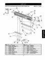
PARTS
LISTFORCRAFTSMAN
TABLESAWBOXJOINTANDMITER
GUIDE
MODEL
NO.171.240300
I
I
I
KEY
NO.
QTY.
PART NO.
DESCRIPTION
KEY
NO,
1
1
29LCN-1080
Guide - Alumlnum
QTY.
PART NO.
DESCRIPTION
12
3
31L-560.1
Three Wing Knob
2
1
29LCN-10#1
3
1
29LCN-1082
Left Lower" Guide
t3
4
29LD-760.2
Round
Knob
Left Slide
14
9
P29A-242-5
#10-24
4
1
Hex Nut
29LCN-1083
Right Lower Guide
15
3
F29A-310.10
#10-24
5
x 1 Carriage
1
29LCN-1084
Right Sllde
16
4
F29A-310.26
#10.24 x 1-3/8 Carringe
6
2
29LCN-1085
End Cap
17
7
F29A-300.13
#10 Wasber
7
1
29LCN-1086
Stop plece
18
1
F29L-460.9
#10 • 3/8 Pan Head Machio!
8
1
2gLCN-1087
Exteninon Tube - Shoql
19
t
45A-395
Product
1
49DC-63
Instruction
1
60870
Tool Set (not illL_trated)
9
1
29LCN-1088
Extension
10
1
29LCN-1069
Fixed Tab
11
1
29LCN-10SO
Adlustable
"_be.
Extrusion
Long
Tab
17
BOR
labelN/arning
Bolt
Screw
Label
Manual (not giostrated)
NOTES
18
NOTES
:19
When corresponding, always give the following
information as shown in the list.
Printed in U.S.A.
05/98
49DC-63
1. The
2. The
3. The
4. The
PART NUMBER
PART DESCRIPTION
MODEL NUMBER: 171.240300
ITEM NAME - TABLE SAW BOX JOINT
AND MITER GUIDE