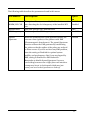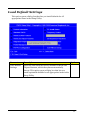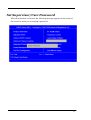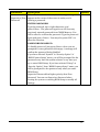
1
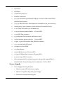
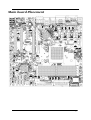
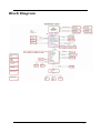
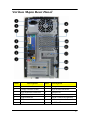
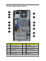
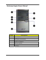
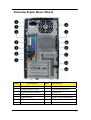
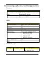
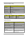
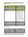
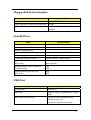
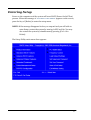
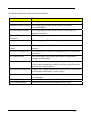
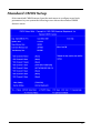
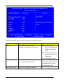
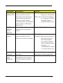
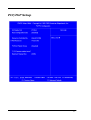
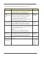
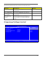
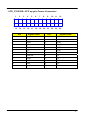
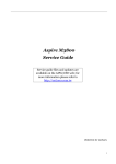
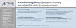
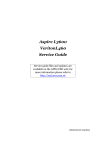
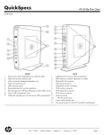
Veriton M420 Veriton M220 Extensa E420 Service Guide Service guide files and updates are available on the AIPG/CSD web; for more information please refer to http://csd.acer.com.tw PRINTED IN TAIWAN Revision History Please refer to the table below for the updates made on Veriton M420/Veriton M220/Extensa E420 service guide. Date Chapter Updates II Copyright Copyright © 2008 by Acer Incorporated. All rights reserved. No part of this publication may be reproduced, transmitted, transcribed, stored in a retrieval system, or translated into any language or computer language, in any form or by any means, electronic, mechanical, magnetic, optical, chemical, manual or otherwise, without the prior written permission of Acer Incorporated. Disclaimer The information in this guide is subject to change without notice. Acer Incorporated makes no representations or warranties, either expressed or implied, with respect to the contents hereof and specifically disclaims any warranties of merchantability or fitness for any particular purpose. Any Acer Incorporated software described in this manual is sold or licensed "as is". Should the programs prove defective following their purchase, the buyer (and not Acer Incorporated, its distributor, or its dealer) assumes the entire cost of all necessary servicing, repair, and any incidental or consequential damages resulting from any defect in the software. Acer is a registered trademark of Acer Corporation. Intel is a registered trademark of Intel Corporation. Pentium 4 and Celeron are trademarks of Intel Corporation. Other brand and product names are trademarks and/or registered trademarks of their respective holders. III Conventions The following conventions are used in this manual: SCREEN Denotes actual messages that appear on screen. MESSAGES NOTE Gives bits and pieces of additional information related to the current topic. WARNING Alerts you to any damage that might result from doing or not doing specific actions. CAUTION Gives precautionary measures to avoid possible hardware or software problems. IMPORTANT Remind you to do specific actions relevant to the accomplishment of procedures. IV Preface Before using this information and the product it supports, please read the following general information. 1. This Service Guide provides you with all technical information relating to the BASIC CONFIGURATION decided for Acer's "global" product offering. To better fit local market requirements and enhance product competitiveness, your regional office MAY have decided to extend the functionality of a machine (e.g. add-on card, modem, or extra memory capability). These LOCALIZED FEATURES will NOT be covered in this generic service guide. In such cases, please contact your regional offices or the responsible personnel/channel to provide you with further technical details. 2. Please note WHEN ORDERING FRU PARTS, that you should check the most up-to-date information available on your regional web or channel. If, for whatever reason, a part number change is made, it will not be noted in the printed Service Guide. For ACER-AUTHORIZED SERVICE PROVIDERS, your Acer office may have a DIFFERENT part number code to those given in the FRU list of this printed Service Guide. You MUST use the list provided by your regional Acer office to order FRU parts for repair and service of customer machines. V Chapter 1 System Specifications 1 Features……………………………………………………………………………………………... 1 Main board Placement…………………………………………………….……..……………..7 Block Diagram…………………………………………………………..………………...………..8 Veriton M420 Front Panel………………………………………..…….………..…..……....9 Veriton M420 Rear Panel…………………..…………………………….……………………10 Veriton M220 Front Panel……………...……………………………………………………..11 Veriton M220 Rear Panel……………………….…………………………………..……….12 Extensa E420 Front Panel……………………………………………………………………..13 Extensa E420 Rear Panel……………………….…………………………………..……….14 Hardware Specifications and Configurations………………….…….……..15 Power Management Function (ACPI support function)…………………………..…...19 Chapter 2 System Utilities 20 Entering Setup…………………………………………………………………………..21 Product Information………………………………………………………..23 Standard CMOS Features……………………………….……………………………………24 Advanced BIOS Features………………………………………..……………………27 Integrated Peripherals…………………………...…………………………………………..31 Power Management…………………………………………………………38 PnP/PCI Configuration…………………………………………………….41 PC Health Status……………………………………………………………...43 Frequency/Voltage Control……………..………………………….…….44 Load Default Settings………………………………………………..……. 46 Set Supervisor/User Password……………………………….…………47 Save & Exit Setup………………………………………………….…………49 Exit Without Saving………………………………………………….……..50 Chapter 3 Machine Disassembly and Replacement 51 General Information………………………………………………………. 52 Disassembly Procedure……………………………………………………53 Aspire M5200/3200/1200 Disassembly Procedure…………….…..……54 Chapter 4 Troubleshooting 73 Chapter 5 Jumper and Connector Information 74 Jumper Setting…………………………………………………..………………..74 Chapter 6 FRU (Field Replaceable Unit) List 82 Exploded Diagram………………………………………………………….83 Chapter 1 System Specifications Features Operating System Microsoft Windows Vista (Home Basic, Home Premium, Business) Processor Socket Type: AMD Socket AM2+ (940 pin) Processor Type: Phenom(95W) / Athlon 64 X2 / Athlon 64/ Sempron CPUs Chipset AMD RS780/RS740 + AMD SB700 PCB Form Factor: MicroATX Dimension/Layer: 244mm*244mm Memory Memory Type: 800 (PC2-6400) /667 (PC2-5300) Support single channel 64 bit mode with maximum memory size up to 8GB Support un-buffered DIMM (RS780/RS740) DIMM Slot: 4 * Note: Main board part number MB.V6109.003 and MB.V6109.004 has 2 memory slots Memory Max: 512Mb/1Gb/2Gb devices technologies Capacity: Up to 2GB per DIMM with maximum memory size up to 8GB only. For more details, please see control table on page 6. PCI PCI Express Slot Type: x16 PCI Express Slot Type: x1 PCI Express x16 Slot Quantity: 1 PCI Express x1 Slot Quantity: 1 PCI Slot Type: PCI 2.25V slots PCI Slot Quantity: 2 1 FDD Slot Quantity: 1 Design Criteria: Should support 1.44MB/3 mode 3.5” Devices IDE Slot Type: 40pin PATA IDE slot Slot Quantity: 1 Transfer rate support: ¾ PIO Mode: 0/1/2/3/4 ¾ ATA mode: 33/66/100/133 Storage Type support: ¾ DVD ROM/DVD SuperMultiPlus SATA Slot Type: SATA slot Slot Quantity: 6 Transfer rate support: ¾ 1.5Gb/s & 3.0Gb/s Storage Type support: ¾ HDD/DVD ROM/DVD SuperMultiPlus Audio Audio Type: HD audio codec Audio Channel: 7.1 channel Audio Controller /Codec: ALC888S HD codec 7.1 Connectors support: Rear 6 jack follow HD audio definition, example as below Audio jacks color coding: should meet Microsoft Windows Logo Program Device Requirements: Audio-0002 2 1 S/PDIF-out header (1*4) 1 AUX-In header (1*4) 1 front panel audio header (2*5) Add HD de-pop CKT (the attachment is the reference, please propose your solution) S/N ratio: 90 dB at rear output jack LAN Controller: Marvell 8071/8075 Gigabit Ethernet controller (VTM220: 8071, VTM420: 8075) Port : 1 x RJ45 rear port for Gigabit Ethernet Design Criteria: Should be worked under 10/100/1000Mbs environment Reserved disable function on both hardware & BIOS side. Default is enabled Support DASH 1.0/1.1 feature USB Controller: AMD SB700 Ports Quantity: 12 (Should we reserve more header for Front DB) 4 port for rear ports On-board: 4 2*5 headers ¾ 4 ports for front daughter board ¾ 2 ports for internal card reader. Connector Pin: standard Intel FPIO pin definition Data transfer rate support: USB 2.0/1.1 1394 Controller: Jmicron JM831 1394a controller 3 Connector Quantity: 2 1 rear 6pin IEEE1394 port 1 2x5pin onboard jumper BIOS BIOS Type: Phoenix Award or AMI Kernel with Acer skin Size: 4Mb or 8Mb Note: Boot ROM should be included (PXE function should be built in with default and RPL function is optional by service BIOS) BIOS shall auto detect FDD to avoid checksum error when boot I/O Connector Controller: Super I/O ITE 8718 Rear I/O Connector 1 PS/2 Keyboard port, 1 PS/2 Mouse port 1 Parallel port header 1 Serial port 1 D-Sub port and 1 DVI-D port (Veriton 2/4 series) 1 DVI-D port and HDMI port (Veriton 6 series) 4 USB ports 1 RJ45 LAN port 7.1 channel phone jack (6 audio jacks) for ALC888S sku On-board connectors 1 CPU socket 4 DDR2 memory sockets 1 PCI Express x16 slot 1 PCI Express x 1 slot 4 2 PCI slots 1 FDD slot 1 PATA IDE connector 6 SATA2 connectors 4 2*5 pin Intel FPIO specification USB pin connectors (follow Intel FPIO standard Specification) 1 2*5 pin Intel FPIO spec. Microphone In/ Headphone Out pin connectors 1 serial port 2*5 pin connector (2nd serial port) (Veriton SKU only) 1 1*4 S/PDIF out header (for ALC888S sku) 1 2*4 pin internal speaker header (Veriton SKU) 1 3 pin CPU Fan connector 1 3 pin System FAN connector with linear circuit 1 2pin Intrusion Alarm connector (Veriton SKU) 1 24pin + 4pin ATX interface PS3/PS2 SPS connector 1 2*7 pin front panel IO header 1 Jumper for clear CMOS 1 on board buzzer 1 2pin OBR header and (Veriton SKU) 1 2*10 pin TPM module connector (Veriton SKU) 2 reserved 2pin GPIO connector Color management for on board connecter (pls provide proposal)M/B should include Jumper Setting label for shipment. (Veriton SKU) Power Supply Power Supply Mounting Features Chassis accepts ATX-style power supply Chasses accepts PS2, PS3 style power supply Features for internal mounting tab 5 Location of 4 external mounting holes Power Supply Electrical Design Feature 300W/250W in stable mode (Acer Assign System Power Unit) Design for Intel Broadwater/ICH8 series chipset compatible system Voltage design should be covered +5V, +3.3V, +12V, +5VSB, -12V (attention to 12V output capability) Demand for both PFC/Non-PFC solutions (two different quotations are needed) Minimum 2 Serial ATA power connector solution should be included (by default) Minimum 3 big 4-pin power connector included Minimum 1 small 4-pin power connector included PFC version will not provide switch selector for 115/230V AC input but it should be universal for Europe and China Non-PFC version should provide switch selector for 115/230V AC input and universal for worldwide PS2 style Click the paperclip icon below for memory slot control table. 6 Main board Placement 7 Block Diagram 8 Veriton M420 Front Panel The computer’s front panel consists of the following: Label Description 1 Optical drive 2 Floppy disk drive 3 Card reader cover(Optional) 4 Microphone jack 5 Speaker or headphone 6 USB 2.0 connector 7 Power button 8 ACER logo 9 Veriton M420 Rear Panel Label Description Label Description 1 Power card socket 8 Fan aperture 2 Voltage selector switch 9 PS/2 mouse connector 3 PS/2 keyboard connector 10 System Fan 4 DVI connector 11 Monitor connector 5 COM connector 12 SPDIF connector(Optional) 6 USB 2.0 connector 13 LAN connector 7 Audio connector 14 Lock Handle 10 Veriton M220 Front Panel Label Description 1 Optical drive 2 Floppy disk drive 3 Card reader cover(Optional) 4 Power button 5 Microphone jack 6 USB 2.0 connector 7 Speaker or headphone 8 ACER logo 11 Veriton M220 Rear Panel Label Description Label Description 1 Power card socket 8 Fan aperture 2 Voltage selector switch 9 PS/2 mouse connector 3 PS/2 keyboard connector 10 System Fan 4 DVI connector 11 Monitor connector 5 COM connector 12 SPDIF connector(Optional) 6 USB 2.0 connector 13 LAN connector 7 Audio connector 14 Lock Handle 12 Extensa E420 Front Panel Label Description 1 Optical drive 2 Floppy disk drive 3 Card reader cover(Optional) 4 Microphone jack 5 Speaker or headphone 6 USB 2.0 connector 7 Power button 8 ACER logo 13 Extensa E420 Rear Panel Label Description Label Description 1 Power card socket 8 Fan aperture 2 Voltage selector switch 9 PS/2 mouse connector 3 PS/2 keyboard connector 10 System Fan 4 DVI connector 11 Monitor connector 5 COM connector 12 SPDIF connector(Optional) 6 USB 2.0 connector 13 LAN connector 7 Audio connector 14 Lock Handle 14 Hardware Specifications and Configurations Processor Item Specification Processor Type Processor Type: Phenom(95W) / Athlon 64 X2 / Athlon 64/ Sempron CPUs Socket AMD Socket AM2+ (940 pin) Minimum operating speed 0 MHz (If Stop CPU Clock in Sleep State in BIOS Setup is set to Enabled.) BIOS Item Specification BIOS code programmer Phoenix Award or AMI Kernel with Acer skin BIOS version V6.0 BIOS ROM type SPI Flash BIOS ROM size 4Mb or 8Mb Support protocol SMBIOS (DMI) 2.4/DMI 2.0 (log file) Device Boot Support - Support to LS-120 drive YES Support to BIOS boot block feature YES 1st priority: SATA HDD 2nd priority: CD-ROM 3rd priority: FDD 4th priority: LAN 5th priority: USB device BIOS Hotkey List Hotkey Del Function Description Enter BIOS Setup Utility Press while the system is booting to enter BIOS Setup Utility. 15 Main Board Major Chips Item Specification North Bridge AMD RS780/RS740 South Bridge AMD SB700 APG controller AMD RS780/RS740 Super I/O controller Super I/O ITE 8718 Audio controller HD audio codec ALC888S HD codec 7.1 LAN controller Marvell 8071/8075 Gigabit Ethernet controller HDD controller AMD SB700 Keyboard controller Super I/O ITE 8718 Memory Combinations Slot Memory Total Memory Slot 1 512Mb/1Gb/2Gb 512MB~2GB Slot 2 512Mb/1Gb/2Gb 512MB~2GB Maximum System Memory Supported 512MB~8GB System Memory Item Specification Memory slot number 4 slot Support Memory size per socket 512Mb/1Gb/2Gb Support memory type DDR2 Support memory interface 800(PC2-6400)/667 (PC2-5300) Support memory voltage 1.8V Support memory module package 240-pin DDR2 Support to parity check feature Yes Support to error correction code (ECC) feature No Memory module combinations You can install memory modules in any combination as long as they match the above specifications. 16 Audio Interface Item Specification Audio controller RS780/RS740 Audio controller type ALC888S Audio channel codec 7.1 Audio function control Enable/disable by BIOS Setup Mono or stereo Stereo Compatibility Sound Blaster Pro/16 compatible Mixed digital and analog high performance chip Enhanced stereo full duplex operation High performance audio accelerator and AC’97 support Full native DOS games compatibility Virtual FM enhances audio experience through real-time FM-to-Wavetable conversionMPU-401 (UART mode) interface for Wavetable synthesizers and MIDI devices Integrated dual game port Meets AC’97and WHQL specifications Music synthesizer Yes, internal FM synthesizer Sampling rate 48 KHz (max.) MPU-401 UART support Yes Microphone jack Supported Headphone jack Supported SATA Interface Item Specification SATA controller RS780/RS740 SATA controller resident bus PCI bus Number of SATA channel SATA X 6 Support bootable CD-ROM YES 17 Floppy disk drive Interface Item Specification Floppy disk drive controller Super I/O ITE 8718 Floppy disk drive controller resident bus ISA bus Support FDD format 360KB, 720KB, 1.2MB, 1.44MB, 2.88MB Parallel Port Item Specification Parallel port controller Super I/O ITE 8718 Parallel port controller resident bus ISA bus Number of parallel parts 1 Support ECP/EPP SPP / Bi-directional / ECP / EPP Connector type 25-pin D-type female connector Parallel port function control Enable/disable by BIOS Setup Optional EV+CP DMA channel (in BIOS setup) DMA channel 1 DMA channel 3 Optional parallel port I/O address (via BIOS setup) 378h 278h Optional parallel port IRQ (via BIOS setup) IRQ5 IRQ7 USB Port Item Specification Universal HCI USB 2.0/1.1 USB Class Support legacy keyboard for legacy mode USB Connectors Quantity 4 ports for front daughter board 6 ports for rear I/O 2 ports for internal card reader. 18 Environmental Requirements Item Specification Temperature Operating +5°C ~ +35°C Non-operating -20 ~ +60°C (Storage package) Humidity Operating 15% to 80% RH Non-operating 10% to 90% RH Vibration Operating (unpacked) 5 ~ 500 Hz: 2.20g RMS random, 10 minutes per axis in all 3 axes 5 ~500 Hz: 1.09g RMS random, 1 hour per axis in all 3 axes Power Management Devices S1 S3 S4 S5 Power Button V V V V USB Keyboard/Mouse V V N/A N/A PME Disabled Disabled Disabled Disabled RCT Disabled Disabled Disabled Disabled WOR Disabled Disabled Disabled Disabled Devices wake up from S3 should be less than Devices wake up from S5 should be less than 10 seconds 19 Chapter 2 System Utilities The manufacturer or the dealer already configures most systems. There is no need to run Setup when starting the computer unless you get a Run Setup message. The Setup program loads configuration values into the battery-backed nonvolatile memory called CMOS RAM. This memory area is not part of the system RAM. NOTE: If you repeatedly receive Run Setup messages, the battery may be bad/flat. In this case, the system cannot retain configuration values in CMOS. Before you run Setup, make sure that you have saved all open files. The system reboots immediately after you exit Setup. 20 Entering Setup Power on the computer and the system will start POST (Power On Self Test) process. When the message of “Press DEL to enter SETUP” appears on the screen, press the key of [Delete] to enter the setup menu. NOTE: If the message disappears before you respond and you still wish to enter Setup, restart the system by turning it OFF and On. You may also restart the system by simultaneously pressing [Ctrl+ Alt+ Delete]. The Setup Utility main menu then appears: 21 The items in the main menu are explained below: Parameter Description Production Information This page shows the relevant information of the main board Standard CMOS Features This setup page includes all the items in standard compatible BIOS Advance BIOS Features This setup page includes all the items of Award special enhanced features Advance Chipset Features This setup page includes all advanced chipset features Integrated Peripherals This setup page includes all onboard peripherals Power Management Setup This setup page includes all the items of Green function features PnP/PCI Configuration This setup page includes all configurations of PCI & PnP ISA resources PC Health Status This setup page is the System auto detect Temperature, voltage, and fan speed Load Optimized Defaults Load Optimized Settings Default Settings indicates the value of the system parameters which the system would be in best performance configuration Set Supervisor Password Change, set or disable password. It allows you to limit access to the system and Setup, or just to Setup Set User Password Change, set or disable password. It allows you to limit access to the System Save & Exit Setup Save CMOS value settings to CMOS and exit setup Exit Without Saving Abandon all CMOS value changes and exit setup 22 Product Information The screen below appears if you select Product Information from the main menu: The Product Information menu contains general data about the system, such as the product name, serial number, BIOS version, etc. This information is necessary for troubleshooting (maybe required when asking for technical support). The following table describes the parameters found in this menu: Parameter Description Production Name This item lists the product name System S/N This item lists the system serial number System BIOS Version This item lists the system BIOS version System BIOS ID This item lists the system BIOS ID BIOS Release Date This item lists the BIOS release date 23 Standard CMOS Setup Select standard CMOS features from the main menu to configure some basic parameters in your system the following screen shows the standard CMOS features menu: 24 The following table describes the parameters found in this menu. Parameter Description Options Date To set the date following the weekday-month-date-year format Week: From [Sun.] to [Sat.]. determined by BIOS and is display only Day: from [1] to [31] (or the maximum allowed in the month. Year: from 1999 to 2099 System Time To set the time following the hour-minute-second format The items format is [hour] [minute][second]. The time is calculated base on the 24-hour timer clock. Base Memory Size 640 K for system base memory 25 Parameter Description Extended Memory Size The BIOS determines how much extended memory is present during the POST. This is the amount of memory located above 1MB in the memory address map of CPU Total Memory Size Total memory size for the system IDE Channel X Master IDE Channel X Slave Hard disk drive connected to channel X master or slave port. To enter the IDE Master or Slave setup, press [Enter]. The IDE CD-ROM is always automatically detected Video Setting Select the type of primary video subsystem Halt on This item enables use to select the situation if the BIOS stops the POST process and the notification Options [Enter] for detection options [Auto]: BIOS automatically detects IDE devices during POST (default) [None]: No IDE devices are used and the system will skip the automatic detection step and allow for faster system start up [Manual]: Manually input the correct settings [Access Mode]: To set the access mode for the hard drive. The four options are: CHS/LBA/Large/Auto (default: Auto) Cylinder: Number of cylinders Head: Number of heads Precomp: Write precomp Landing Zone: Landing Zone Sector: Number of sectors All Errors No Errors All, But Keyboard All, But Diskette All, But Disk/Key 26 Advanced Setup The following screen shows the Advanced Setup: The following table describes the parameters found in this menu. Parameter Description Options Hard Disk Boot Priority This features displays the Hard Disk Boot Device priority from high to low and allows users to set the Hard Disk Boot Device Priority. Press [Enter] to enter the setting screen. Use wory to select a device, then press <+> to move it up, or <-> to move it down the list. Press <ESC> to exit. [Press Enter] 27 Parameter Description Options Virus Warning This feature allows you to enable the VIRUS warning function for IDE Hard Disk boot sector protection. If this function is enabled and there is someone attempts to write data to this area, BIOS will show a warning message on screen and the alarm will beep. [Enabled], [Disabled] Quick Power On Self Test This feature allows the system to skip certain tests while booting. When this function is enabled, it will decrease the time needed to boot the system, which means to quick power on self-test function. [Enabled], [Disabled] Silent Boot This feature allows you to enable or disable if the [Enabled], [Disabled] screen logo to display or not during POST First/Second/ Third Boot Device The item allows you to see the sequence of boot device where BIOS attempts to load the disk operation system. Boot From Other Devices This item allows user to enable or disable to boot [Enabled], [Disabled] from other device Boot Up NumLock Status This item allows user to enable or disable to set keyboard is number keys or arrow keys [Enabled], [Disabled] Security Option This category allows you to limit access to the system and Setup, or just to Setup. [System], [Setup] APIC Mode This option is used to set up enable or disable the APCI function [Enabled], [Disabled] HDD S.M.A.R.T Capability S.M.A.R.T. which allows your hard disk to report [Enabled], [Disabled] any read/write errors and issue a warning when LDCM installed [Floppy], [LS120], [Hard Disk], [CD-ROM], [ZIP], [USB-FDD], [USB-ZIP], [USB-CDROM], [USB-HDD], [LAN], [Disabled] 28 Advanced Chipset Setup The following table describes the parameters found in this menu. Parameter Description Options Dual Monitor Support This category allows you to enable or disable dual monitor support function [Enabled], [Disabled] Frame Buffer Size This field displays how much frame buffer size of the system. CPU Frequency This field allows you to determine CPU frequency of the system. 29 Parameter Description Options Spread Spectrum When the system clock generator pulses, the extreme values of the pulse generate excess EMI. Enabling pulse spectrum spread modulation changes the extreme values from spikes to flat curves, thus reducing EMI. This benefit may in some case be outweighed by problems with timing-critical devices, such as a clock-sensitive SCSI device. [Enabled], [Disabled] HT Spread Spectrum Enables or Disables HT Spread Spectrum. HT is Hyper Transport between CPU and North Bridge. [Enabled], [Disabled] SSE/SSE2 Instructions This feature controls the availability of the [Enabled], [Disabled] processor’s SSE and SSE2 instruction sets. When enabled, the processor’s SSE and SSE2 instruction sets are enabled. Software applications can make use of those instructions to better process large amounts of data quickly. When disabled, the processor’s SSE and SSE2 instruction sets are disabled. Software applications will not be able to use those instructions to process multiple data elements simultaneously. However, the processor’s MMX instruction set will still be available for use. It is highly recommended that you leave this BIOS feature at the default setting. 30 Integrated Peripherals The following table describes the parameters found in this menu. Parameter Description Options IDE Function Setup This page allows you to setup IDE function [Press Enter] Onboard Device Setup This page allows you to setup onboard devices. [Press Enter] Onboard I/O Chip Setup This page allows you to setup onboard I/O chip. [Press Enter] 31 Integrated Peripherals-IDE Function Setup 32 The following table describes the parameters found in this menu. Parameter Description IDE Primary/Second ary Master/Slave PIO The four IDE PIO fields let you set a PIO mode (0-4) for each of the four IDE devices that the onboard IDE interface supports. Modes 0 through 4 provide increased performance. In Auto mode, the system automatically determines the best mode for each device. On-Chip IDE First/Second Channel The Chipset contains a PCI IDE interface with support for two IDE channels. Select Enabled to activate the first and/or second IDE interface. Select Disabled to deactivate an interface, if you install a primary and/or secondary add-in IDE interface. IDE Primary/Second ary Master/Slave UDMA UDMA (Ultra DMA) is a DMA data transfer protocol that utilized ATA transfer protocol that utilizes ATA commands and the ATA bus to allow DMA commands to transfer data ata maximum burst rate of 33 MB/s. When you select Auto in the four IDE UDMA fields (for each of up to four IDE devices that the internal PCI IDE interface supports), the system automatically determines the optimal data transfer rate for each IDE device. IDE DMA Transfer Access This category allows you to enable or disable DMA transfer access of IDE device (or IDE HDD) SATA 1/2 Enable/Disable Serial-ATA 1 or Serial-ATA-2. SATA 1 control port 1 and 3, SATA 2 control port 2 and 4. IDE Prefetch Mode The onboard IDE drive interfaces supports IDE prefetching, for faster drive accesses. If you install a primary and/or secondary add-in IDE interface, set this field to Disabled if the interface does not support prefetching. Options [Enabled], [Disabled] [Enabled], [Disabled] 33 Parameter Description Options IDE HDD Block Mode Block mode is also called block transfer, multiple commands, or multiple sectors read/write. If your IDE hard drive supports block mode(most new drives do), select Enabled for automatic detection of the optimal number of block read/write per sector the drive can support. [Enabled], [Disabled] SATA PORT Speed Settings This category allows you to determine the speed of SATA port. [Auto], Integrated Peripherals-Onboard Device Setup 34 The following table describes the parameters found in this menu. Parameter Description Options On Chip USB This field allows you to determine on chip USB type or disable on chip USB. [V1.1+V2.0], [V1.1] UDB Memory Type Use this item to change the type of USB memory to shadow or Base memory. [Shadow], [Base Memory] USB KB Legacy Support This field enables or disables USB keyboard support function. [Enabled], [Disabled] USB Mouse Support This field enables or disables USB mouse support function. [Enabled], [Disabled] ALC888S Audio Change the on board Audio to auto or disabled [Auto], [Disable] MAC LAN Enables or disables onboard LAN [Enabled], [Disabled] controller, If you wish to use the motherboard’s onboard LAN controller, you should certainly enable this BIOS feature. You can disable this feature if you do not want to use the motherboard’s onboard LAN controller. This may free up an IRQ for other devices to use. This is useful if your motherboard does not support APIC and have many devices that can not share IR Qs. MAC LAN Boot ROM Enables or disables on board LAN boot ROM. [Enabled], [Disabled] 35 Integrated Peripherals -Onboard I/O Chip Setup 36 The following table describes the parameters found in this menu. Parameter Description Options Onboard FDC Controller Select Enabled if your system has a floppy disk controller (FDC) installed on the system board and you wish to use it. If you install an add-in FDC or the system has no floppy drive, select Disabled in this field. [Enabled]. [Disabled] Onboard Serial Port 1 Select a logical COM port name and matching address for the serial port. Select an address and corresponding interrupt for the serial port. UR2 Duplex Mode In an infrared port mode, this field appears. Full-duplex mode permits simultaneous tow-direction transmission. Half-duplex mode permits transmission in one direction only at a time. Select the value required by the IR device connected to the IR port. Onboard Parallel Port Select a logical LPI port address and corresponding interrupt for the physical parallel port. [xxx+IRQx] Parallel Port Mode Select an operating mode for the onboard parallel (printer) port. [Normal], [EPP], [EPP], [EPP+ECP] ECP Mode used DMA This item allows users to manually set the DMA channel for ECP mode 37 Power Management The Power Management menu lets you configure your system to most effectively save energy while operating in a manner consistent with your own style of computer use. The following screen shows the Power Management parameters and their default settings: 38 The following table describes the parameters found in this menu. Parameter Description Options ACPI Function This item allows you to enable or disable the ACPI function [Enabled], [Disabled] ACPI Suspend Type This item specifies the power saving modes for ACPI function. S1 (POSP: The S1 sleep mode is a low power state.. In this state, no system context (SPU or chipset) is lost and hardware maintains all system context/ S3 (STR): The S3 sleep mode is s power-down state in which power is supplied only to essential components such as main memory and wake-capable devices and all system context is saved to main memory. The information stored in memory will be used to restore the PC to the previous state when an wake-up event occurs. [S1 (POS)]: Set ACPI suspend type to S1/POS (Power On Suspend). [S3 (STR)]: Set ACPI suspend type to S3/STR HDD Power Down The setting controls how long a hard disk drive must be left idle before it spins downs. [Disabled], [Standby], [Suspend] HDD Down In Suspend Enables or Disables the functionality of HDD down in suspend [Enabled], [Disabled] 39 Parameter Description Options Soft-off by PWR/BTTN When Enabled, turning the [Instant-off]: Press down button system off with the on/off then power off instantly button places the system in a [Delay 4 Sec.]: Press Power button 3 very low-power-usage state, sec. to power off. Enter with only enough circuitry suspend if button is receiving power to detect power pressed less than 4 sec. button activity or Resume by Ring activity. WOL (PME#) From Soft-Off This category enables or disables wake-on-Lan from soft-off [Enabled], [Disabled] Resume by Alarm You can set “Resume by Alarm” item to enabled and key in Date/Time to power on system. [Disabled] [Enabled]: Enable alarm function to Power On system. If RTC Alarm Lead to Power On is Enabled, Date( of Month) Alarm: Everyday, 1~31 Time(hh:mm:ss) Alarm: (0.~23):(0-59):(0~59) POWER ON Function Select the method to power on the system [Button Only], [Keyboard 98], [Hot Key], [Mouse Left], [Mouse Right] POWER After PWR-Fail This field allows you to determine the power status to on/off or former-sts after the system [FORMER-Sts], [On], [Off] 40 PCI/PnP Setup 41 The following table describes the parameters found in this menu. Parameter Description Options Init Display First Initialize the AGP video display before initializing any other display device on the system. Thus the AGP display becomes the primary display. Reset Configuration Data Normally, you leave this field Disabled. Select Enabled to reset Extended System Configuration Data (ESCD) when you exit Setup if you have installed a new add-on and the system reconfiguration has caused such a serious conflict that the operating system cannot boot [Enabled], [Disabled] Resources Controlled By This item allows user to assign PnP resource (I/O address, IRQ&DMA channels) for Plug and Play compatible devices automatically or manually [Auto] [Manual] IRQ Resources When resource are controlled by manually, assign [Press Enter] each system interrupt a type , depending on the type of device using the interrupt. Option: [PCI Device]: Assign this IRQ for PCI device. [Reserved]: Reserve this IRQ for other device. PCI/VGA Palette Snoop This option is only very rarely needed. It should be left at “Disabled” unless a video device specifically requires the setting enabled upon installation. Maximum Payload Size This field displays maximum payload size of the system PCI 1/2 IRQ Assignment This item allows user to assign PCI IRQ for device [Disabled], [Enabled] [128-4096] [Auto], [3] , [4] , [5] , [6] , [7], [10] , [11] , [12] , [14] , [15] 42 PC Health Status 43 The following table describes the parameters found in this menu: arameter Description V core Detect system’s voltage status automatically CPU Temperature Detect CPU Temperature automatically CPU/SYSTEM FAN Speed (RPM) Detect CPU/SYSTEM Fan Speed Status automatically CPU Smart FAN Control The item displays the system Smart Fan Function status. It is always enabled by system. Options Frequency/Voltage Control CMOS Setup Utility - Copyright (C) 1985-2005,American Megatrends,Inc. Frequency/Voltage Control Manufacturer: Intel Help Item Ratio Status: Unlocked (Min:06,Max:10) Ratio Actual Value: 10 Options CPU Frequency : 1800MHz Auto Detect DIMM/PCI CLK Enabled Disabled Spread Spectrum Enabled Enabled ¢ ٛ :Move Enter: Select +/-/:Value F10:Save ESC:Exit F1:General Help F9:Optimized Defauits 44 The following table describes the parameters found in this menu: Parameter Description Optio ns Auto Detect DIMM/PCI CLK This option allows you to enable/disable the feature of auto detecting the clock frequency of the installed PCI bus. Enabled Disabled Manufacturer This item specifies CPU Manufacturer Intel CPU frequency This item specifies CPU frequency 1800MH z Spread Spectrum When the motherboard’s clock generator pulses, the extreme values (spikes) of the pulses create EMI (Electromagnetic Interference). The spread Spectrum function reduces the EMI generated by modulating the pulses so that the spikes of the pulses are reduced to flatter curves. If you do not have any EMI problem, leave the setting at Disabled for optimal system stability and performance. But if you are plagued by EMI, setting to Enabled for EMI reduction. Remember to disable Spread Spectrum if you are overlooking because even a slight jitter can introduce a temporary boost in clock speed which may just cause your over lock ed processor to lock up. Enabled 45 Load Default Settings This option opens a dialog box that lets you install defaults for all appropriate items in the Setup Utility. Parameter Description Load Default Settings Select the field loads the factory defaults for BIOS and Chipset Features, which the system automatically detects. This option opens a dialog box that lets you install optimized defaults for all appropriate items in the Setup Utility. Options 46 Set Supervisor/User Password When this function is selected, the following message appears at the center of the screen to assist you in creating a password. 47 Parameter Description Options Set When this function is selected, the following message Supervisor/User appears at the center of the screen to assist you in Password creating a password. ENTER PASSWORD Type the password, up to eight characters, and press<Enter>. The password typed now will clear any previously entered password from CMOS Memory. You will be asked to confirm the password. Type the password again and press <Enter>. You may also press<ESC> to abort the selection. PASSWORD DISABLED To disable password, just press<Enter> when you are prompted to enter password with empty. A message will confirm the password being disabled. If you have selected “System” in “Security Option” of “BIOS Feature Setup” menu, you will be prompted for the password every time the system reboots or any time you try to enter BIOS Setup. If you have selected “Setup” at “Security Option” from “BIOS Features Setup” menu, you will be prompted for the password only when you enter BIOS Setup. Supervisor Password has higher priority than User Password. You can use Supervisor Password when booting the system or entering BIOS Setup to modify all settings. 48 Save & Exit Setup Highlight this item and press <Enter> to save the changes that you have made in the Setup Utility and exit the Setup Utility. Parameter Description Options Save & Exit Setup Press <Enter> to save the changes that have made in the Setup Utility and exit the Setup Utility. Press<Y> to save and Exit or <N> to return to the main menu. 49 Exit Without Saving Highlight this item and press <Enter> to discard any changes that you have made in the Setup Utility and exit the Setup Utility. Parameter Description Exit Without Saving Press<Enter> to discard any changes and exit the Setup Utility Options 50 Chapter 3 Machine Disassembly and Replacement To disassemble the computer, you need the following tools: Wrist grounding strap and conductive mat for preventing electrostatic discharge. Wire cutter. Phillips screwdriver (may require different size). NOTE: The screws for the different components vary in size. During the disassembly process, group the screws with the corresponding components to avoid mismatches when putting back the components. 51 General Information Before You Begin Before proceeding with the disassembly procedure, make sure that you do the following: 1. Turn off the power to the system and all peripherals. 2. Unplug the AC adapter and all power and signal cables from the system 52 Disassembly Procedure This section tells you how to disassemble the system when you need to perform system service. Please also refer to the disassembly video, if available. CAUTION: Before you proceed, make sure you have turned off the system and all peripherals connected to it. 53 Veriton M420/220/Extensa E420 Standard Disassembly Process Bezel Label Process: 1. According to the requirement, paste ATI, OS, CPU, HDMI and marketing label by SKU. Veriton M420 54 Veriton M220 Extensa E420 55 ODD install place Notice: I. Dual ODD assembly rule. Master ODD Slave ODD ODD Master ODD SUPERMULTI+ V DVD-DUAL V COMBO V CD-RW DVD V Slave ODD V CD-ROM V Remove side cover Process: 1. Put the Computer on the worktable lightly. 2. Release left side cover with 2 screws then remove left side cover. 56 Screw location Push the side cover Screw location Remove Front Bezel Process: 1. Remove the power switch cable from M/B F_PANEL port. 2. Remove front bezel from chassis. 57 Remove Cards Process: 1. Release the slot cover tooless 2. Remove VGA 、TV、Modem Card,the following list is for your reference about the mutual location relation (Optional by SKU). Modem card TV card VGA card Notice: I. Remove card, don’t touch any electric parts on PCB. TV card VGA card Modem card 58 Remove HDD Data Cables Process: 1. Remove HDD/ODD data cable from M/B. 2. Remove master HDD data & power cable. SATA2 SATA1 Port SATA1 SATA2 SATA3 SATA4 SATA4 Forward Master HDD Master ODD Slave HDD Slave ODD SATA3 HDD data cable Connect FDD Connect Master HDD HDD power cable Connect Slave HDD 59 Remove ODD DATA cable Process: 1. Remove master ODD data and power cable from ODD. 2. Remove slave ODD data and power cable from master and Slave ODD (Optional by SKU) ODD data cable ODD power cable 60 Cable routing Process: 1. Put master HDD Cable into HDD1 slot, And Put Slave HDD Cable into HDD2 slot Remove Cables Process: 1. Remove Audio cable from M/B “F-AUDIO”。 2. Remove card reader cable from M/B “USB2” 3. Remove USB1 cable from M/B “F_USB4” 4. Remove USB2 cable from M/B “F_USB3” 5. Remove recovery cable from M/B. 6. Remove the“Intrusion” cable from M/B. 61 cable clip USB 4 port USB 3 port Card reader Front audio cable “Recovery” cable location “Intrusion” cable location 62 Notice: I. Front panel USB cable must be always connect to M/B USB2 and USB3 port whether has card reader. II. The black cable of them is requested to close to the cooler when connecting “Recovery"cable. III. The red cable of them is requested to close to PCI slot with MB when connecting “Intrusion” cable; Paste clip/Cable routing Process: 1. We should paste a cable clip on bottom, Put audio cable into the cable clip 2. Cable routing. Paste 1pcs cable clip Put audio/USB/Card reader/1394 cable into the cable clip 63 Remove HDD Process: 1. Remove Master HDD from the first HDD location. 3. Remove Slave HDD from the second HDD location. (Optional by SKU) Slave HDD Master HDD Remove card reader Process: 1. Remove card reader from chassis. 64 Remove FDD Cable Process: 1. Remove FDD digital cable just as pictures (Optional by SKU). 2. Plug 4 pins power cord from FDD slot. Remove from FDD Remove from M/B “FDD1” slot A Only card reader B Card reader Only FDD FDD Card reader and FDD FDD Card d 65 Remove ODD Process: 1. Push the lock handle release ODD. 2. Remove Master ODD from the location. 3. Remove slave ODD from the location. (Optional by SKU) Master ODD location Slave ODD location 66 Remove Cables Process: 1. Remove 12V power cable from M/B connector “PWR2”. 2. Remove System fan cable from M/B connector “SYS FAN ”. 3. Remove P1 power cable from M/B connector “PWR”. 4. Remove heat sink cable from M/B connector “CPU_ FAN". 12V power cable System fan cable CPU- FAN P1 power cable Remove the Insert TPM card and speaker Process: 1. Remove the TPM card from M/B TPM connector (Optional by SKU). 2. Remove the speaker from Chassis. 67 TPM card II Remove the speaker 25mm I Audio 10mm speaker 25mm I III IV Audio 10mm II Note: I. Must take of the direction when connect the cables. 68 Remove System FAN Process: 1. Release four screws according to the following picture. 2. Remove Sys FAN (Optional by SKU) Release four screws. 4 1 2 3 The direction of System FAN 69 Remove mother board Process: 1. Release 8PCS screws form the corresponding hole. 2. Release screws according to the following picture in turn. 3. Remove the Mother board from chassis. 3 1 5 6 7 4 8 2 Raised platform 70 Remove CPU cooler Process: 1. Release the clip and remove Cooler from the Retention module. Remove memory Process: 1. Open the memory slot then remove memory. 2. Remove the first Memory from DIMM1 slot. 3. Remove the second Memory from DIMM2 slot (Optional by SKU). DIMM1 DIMM2 Memory install place DIMM 1 DIMM 2 DIMM 3 A B A A B B A A A B A A B DIMM 4 Open the memory slot then remove memory. B 71 Remove CPU Process: 1. Remove CPU according following the pictures. Corresponding Open the handle then removes CPU Remove I/O shielding Process: 1. Remove I/O Shielding. 72 Chapter 4 Troubleshooting Please refer to generic troubleshooting guide for troubleshooting information relating to following topics: Power-On Self-Test (POST) POST Check Points POST Error Messages List Error Symptoms List 73 Chapter 5 74 75 ATX_POWER: ATX 24-pin Power Connector 1 2 3 4 5 6 7 8 9 10 11 12 13 14 15 16 17 18 19 20 21 22 23 24 Pin Signal Name Pin Signal Name 1 +3.3 13 +3.3V 2 +3.3 14 -12V 3 COM 15 COM 4 +5V 16 PS_ON 5 COM 17 COM 6 +5V 18 COM 7 COM 19 COM 8 PWR OK 20 -5V 9 5VSB 21 +5V 10 +12V 22 +5V 11 +12V 23 +5V 12 +3.3V 24 COM 76 77 78 79 80 81 Chapter 6 FRU (Field Replaceable Unit) List This chapter gives you the FRU (Field Replaceable Unit) listing in global configurations of Veriton M420/Veriton M220/Extensa E420. Refer to this chapter whenever ordering for parts to repair or for RMA (Return Merchandise Authorization). NOTE: Please note WHEN ORDERING FRU PARTS that you should check the most up-to-date information available on your regional web or channel. For whatever reasons a part number change is made, it will not be noted in the printed Service Guide. For ACER-AUTHORIZED SERVICE PROVIDERS, your Acer office may have a DIFFERENT part number code to those given in the FRU list of this printed Service Guide. You MUST use the local FRU list provided by your regional Acer office to order FRU parts for repair and service of customer machines. 82 Exploded Diagram NO DESCRIPTION NO DESCRIPTION 1 3.5’FILLER PANEL 11 USB BOARD 2 5.25’ROTATE COVER 12 USB BKT 3 V451 BEZEL 13 RIGHT-SIDE 4 CD-ROM 14 CHASSJS 5 FDD-VJTH-PANEL 15 POWER SUPPLY 6 HDD-DISK 16 FAN 7 MOTHER BOARD 17 PCI-BKT 8 HDD-LOCK-SLIDE 18 LEFT-SIDE 9 FDD-LOCK-SLIDE 10 CDROM-LOCK-SLIDE 83 NO DESCRIPTION NO DESCRIPTION 1 3-25-COVER 11 USB BOARD 2 5-25-COVER 12 USB BKT 3 VM200 BEZEL 13 RIGHT-SIDE 4 CD-ROM 14 CHASSIS 5 FDD-VJTH-PANEL 15 POWER-SUPPLY 6 HDD-DISK 16 FAN 7 NOTHER BOARD 17 PCI-BKT 8 HDD-LOCK-SLIDE 18 LEFT-SIDE 9 FDD-LOCK-SLIDE 19 10 CDROM- LOCK-SLIDE 20 84 NO DESCRIPTION NO DESCRIPTION 1 EM200_MAIN_BEZEL 11 FAN 2 3.25-COVER 12 PCI-BRACKET 3 5.25-COVER 13 LEFT SIDE DOOR 4 USB-SHIELDING 14 MOTHERBOARD 5 USB-PCB-ASM 15 HDD-LOCK-SLIDE 6 FDD-LOCK-SLIDE 16 HDD 7 CD-ROM LOCK SLIDE 17 3.5’ DEVICE 8 CHASSIS 18 CD-ROM 9 RIGHT SIDE DOOR 19 10 POWER SUPPLY 20 85