1
ZONE CONTROL SYSTEM
INSTALLATION AND OPERATION MANUAL
TABLE OF CONTENTS
1. INTRODUCTION .............................................................................................................................1
1.1 IMPORTANT NOTE....................................................................................................................................1
1.2 FEATURES.................................................................................................................................................1
1.3 SAFETY INSTRUCTIONS..........................................................................................................................2
2. APPLICATION AND DESIGN CONSIDERATIONS ........................................................................2
3. COMPONENT REQUIREMENTS ...................................................................................................3
3.1 BASIC SYSTEM ........................................................................................................................3
3.2 EXPANDER MODULE ...............................................................................................................3
3.3 ENVIRONMENTAL MODULE ....................................................................................................4
3.4 SIZING TRANSFORMERS ........................................................................................................4
3.5 SIZING DAMPERS ....................................................................................................................4
3.6 TYPICAL SYSTEM DIAGRAM...................................................................................................4
4. SYSTEM INSTALLATION................................................................................................................6
4.1 SLIMZONE PREMIER CONTROL MODULE (SZP) ..................................................................................6
4.1.1 REMOVAL AND INSTALLATION OF THE DOOR .........................................................................6
4.1.2 INSTALLATION OF THE BACKPLATE ..........................................................................................6
4.2 THERMOSTAT INSTALLATION: DSL-520P...............................................................................................7
4.3 DAMPERS..................................................................................................................................................7
4.4 WIRING INFORMATION ..........................................................................................................................10
4.5 CURRENT LIMITED OUTPUT TERMINALS ...........................................................................................10
4.6 SLIMZONE ENVIRONMENTAL MODULE (SZEM)..................................................................................11
5. SYSTEM OPTIONS AND OPERATION ........................................................................................12
5.1 INTERACTION BETWEEN MODULES ...................................................................................................12
5.1.1 SZP CONTROL MODULE............................................................................................................12
5.1.2 DSL-520P ZONE THERMOSTAT.................................................................................................13
5.1.3 SZEM ENVIRONMENTAL MODULE ...........................................................................................14
5.2 SYSTEM PROGRAMMING......................................................................................................................14
5.2.1 PROGRAMMING FEATURES .....................................................................................................14
5.2.2 SCHEDULES................................................................................................................................14
5.2.3 FACTORY DEFAULTS .................................................................................................................15
5.3 USER OPTIONS ......................................................................................................................................15
5.4 HVAC OPTIONS.......................................................................................................................................15
5.5 CONTROL METHODS .............................................................................................................................16
5.5.1 TIMESHARE.................................................................................................................................16
5.5.2 DIFFERENTIAL ............................................................................................................................16
5.6 SEQUENCE OF OPERATION .................................................................................................................17
5.6.1 TIMESHARE MODE.....................................................................................................................17
5.6.2 DIFFERENTIAL MODE ................................................................................................................18
5.7 USER INTERFACE ..................................................................................................................................18
5.7.1 LCD SYMBOL DESCRIPTION.....................................................................................................18
5.8 FLOW DIAGRAM .....................................................................................................................................19
SlimZone Premier
i
6. START UP AND TEST...................................................................................................................22
TROUBLESHOOTING GUIDE ...............................................................................................................26
GLOSSARY ............................................................................................................................................27
APPENDIX A: LIST OF FIGURES ........................................................................................................28
APPENDIX B: LIST OF TABLES ..........................................................................................................28
ZONE SCHEDULE .................................................................................................................................29
ZONE DIAGRAM....................................................................................................................................30
WARRANTY ...........................................................................................................................................31
ii
SlimZone Premier
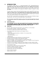
1.
INTRODUCTION
The SlimZone Premier (SZP) is a commercial/residential HVAC (Heating/Ventilation/Air
Conditioning) zone control system which allows control of up to nineteen (19) zones with a
single HVAC system. Each zone is controlled by its own zone thermostat and motorized
damper. The control module monitors the zone thermostats, sets the HVAC system in the
appropriate mode of operation, and energizes the number of stages of heating or cooling
accordingly.
The basic system consists of the main SlimZone Premier control module (SZP-3) which may
control up to three (3) zones. The modular nature of this system allows the expansion of the
number of controlled zones by simply adding SlimZone Expander modules (SZEX) which add
two (2) zones to the system per module. Up to eight (8) expander modules may be connected
to the control module, allowing a total of nineteen (19) zones.
Only DSL-520P communicating zone thermostats may be used with the SlimZone Premier
Control module. Each zone to be controlled requires a zone thermostat.
The user interface to the SlimZone Premier consists of a four (4) button keypad and a four (4)
line by twenty (20) character LCD display, through which all system information may be viewed
or modified.
1.1
IMPORTANT NOTE
IT IS IMPORTANT THAT YOU READ AND UNDERSTAND THIS MANUAL SUPPLIED WITH
THE SLIMZONE PREMIER, AS WELL AS THE HVAC EQUIPMENT MANUFACTURER’S
INFORMATION, BEFORE BEGINNING INSTALLATION OF THE SYSTEM.
1.2
FEATURES
•
•
•
•
•
•
•
•
•
•
•
•
•
•
•
•
•
Ultra slim styled cabinet (8-7/8" (22.5cm)W x 9-1/2" (24cm)H x 1-3/4" (4.5cm)D)
Two (2) modes of operation: timesharing or differential
Four (4) lines by twenty (20) characters backlit LCD display
User friendly interface which allows access to features such as:
- panel setup
- system programming (temperatures, schedules, 2 or 4 events per day)
- 12 or 24 hour clock
- temperature display in °F or °C
- equipment test
LED (light emitting diode) status indicators on all system functions
Solid state control module with current limited relay outputs
Controls heat pumps, cooling units and gas, oil or electric furnace units
Number of controlled zones expandable to nineteen (19) in increments of two (2) zones by
ordering the SlimZone Expander module (SZEX)
Controls up to four (4) stages of heating and three (3) stages of cooling in heat/cool mode
Controls up to three (3) stages of heating and three (3) stages of cooling in heat pump mode
Two (2) speed fan output
Forty-five (45) second fan purge into last zone(s) calling
Constant or automatic fan during occupied cycle
Two (2) or three (3) wire damper capability
Perimeter heat control from zone thermostats
High/Low limit downstaging
High/Low balance control
SlimZone Premier
1
•
•
•
•
•
•
1.3
SAFETY INSTRUCTIONS
•
•
•
•
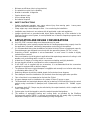
2.
Sudden equipment operation may cause serious injury from moving parts. Leave power
disconnected until installation is complete.
Sharp edges may cause damage to wires. Use care during the installation.
Installation must be done in accordance with all applicable codes and regulations.
Installer should touch a grounded metal object before handling any of the modules in the
SlimZone Premier control system, to avoid potential loss of internal computer programs due to
static discharge.
APPLICATION AND DESIGN CONSIDERATIONS
A.
B.
C.
D.
E.
F.
G.
H.
I.
J.
K.
L.
M.
N.
O.
P.
Q.
2
Minimum on/off times (short cycle protection)
Occupied/unoccupied cycle capability
Manual or automatic changeover
Smoke detector input
All low voltage wiring
No batteries required
Only DSL-520P communicating zone thermostats may be used.
Air conditioning control systems require that the air handling equipment be properly sized for
the application; otherwise, satisfactory temperature control may not be realized.
It is recommended that system installations be limited to thirty (30) tons of equipment capacity.
Enerstat dampers are designed to work only with low pressure systems (1.0" WC or less).
Oversizing of HVAC equipment is not recommended. In most cases it is better to slightly
undersize than oversize.
Extra consideration should be given in applications that require large amounts of cooling in cold
weather, such as buildings with a center or core area.
At least two (2) stages of cooling and/or compressor unloading are highly desirable.
Hot gas bypass should be considered on some commercial systems.
If the HVAC unit is supplied with an economizer, it is recommended that the economizer
package be equipped with a relief air damper.
The pressure drop across typical dampers is negligible and normally is not a factor when sizing
or calculating branch duct CFM.
Balancing dampers should be installed ahead of all motorized zone dampers.
Zone dampers should be installed ten (10) feet back from discharge grille when possible.
Flex or lined duct is recommended on the last five (5) feet.
A bypass damper must be installed on all systems of three (3) zones or more.
The thermostats and motorized dampers may be located up to 300 feet (90m) from the control
module, using nonshielded 3 (dampers) and 4 (thermostat) conductor 18 - 24AWG copper
wires.
A maximum load of 2.5 Amps may be switched by the output terminals, which complies with
Class 2 wiring code.
System wires should be tagged to match the module terminal designations.
The addition of equipment heating and cooling limits, as provided by the SlimZone
Environmental module (SZEM), is strongly recommended and will greatly help in preventing
temperature swings as well as constant heating/cooling changeover.
SlimZone Premier
R.
S.
T.
All zones served by a SlimZone control module should have the same basic load characteristics
(i.e., do not put 4 zones on an east exposure, and the 5th zone on a southwest exposure).
All references to typical dampers refer to Enerstat model dampers.
Zones 14-19 adhere to the same schedule and act as a single call for equipment. Although they
are separate physical zones they act as a single zone when communicating with the SZP
Control module. It is recommended that when considering the layout of your zone system,
zones 14-19 should be assigned to areas of low priority.
3.
COMPONENT REQUIREMENTS
3.1
BASIC SYSTEM
The basic system consists of the main SlimZone Premier Control module (SZP-3: 3 zone
module) and its supporting components.
ITEM
SZP-3 control module
DSL-520P zone thermostat
QUANTITY
one (1)
one (1) per zone
Motorized zone dampers
one (1) per zone (minimum)
24VAC transformers
one (1) for main module
zone dampers powered by
separate transformer(s)
CONSIDERATIONS
contains three (3) zones
use standard nonshielded 4
conductor 18-24AWG copper wire
use standard nonshielded 3
conductor 18AWG copper wire
75VA
refer to section 3.4 for sizing
Table 3.1: SlimZone Premier Basic Components
3.2
EXPANDER MODULE
Each SlimZone Expander module (SZEX) consists of two (2) additional zones.
expander module added, the following items are required:
ITEM
SZEX expander module
DSL-520P zone thermostat
QUANTITY
one (1)
one (1) per zone
Motorized zone dampers
one (1) per zone (minimum)
24VAC transformers
SZEX powered by SZP
zone dampers powered
by separate transformer(s)
For each
CONSIDERATIONS
contains two (2) zones
use standard nonshielded 4
conductor 18-24AWG copper wire
use standard nonshielded 3
conductor 18AWG copper wire
N/A
refer to section 3.4 for sizing
Table 3.2: SlimZone Expander Module Components
Note: Expander module itself does not require a transformer as it is powered by the control
module.
SlimZone Premier
3
3.3
ENVIRONMENTAL MODULE
ITEM
SZEM environmental module
Motorized bypass damper
24VAC transformer
QUANTITY
one (1)
CONSIDERATIONS
contains two (2) remote temperature
probes, and PVC tubing for static
pressure
use standard nonshielded 2
conductor 18-24 AWG copper wire
to connect to SZP
one (1) - may require two (2) use standard nonshielded 3
in larger systems
conductor 18AWG copper wire
one (1)
20VA (300mA)
Table 3.3: SlimZone Environmental Module Components
3.4
SIZING TRANSFORMERS
To avoid unsatisfactory operation DO NOT power the SZP control module with the HVAC
equipment transformer. A dedicated field supplied 24VAC, 75VA transformer is recommended
to power the control module, which in turn may have up to nineteen (19) zones connected to
it. Zone dampers require separate transformers.
Zone dampers may be powered by individual zone transformers or by a single transformer. A
single transformer used to power more than one damper must have a sufficient power rating
(VA) to energize all dampers. To determine the total power requirements, add each damper’s
VA rating. Typical dampers require a maximum of 12VA each. This total must not exceed the
VA rating of the transformer.
3.5
SIZING DAMPERS
It is important that dampers be sized according to system ductwork specification (CFM) and
balanced in compliance to SMACNA, ACCA and ASHRAE guidelines in order for the control
system to properly control comfort in each zone. Typical dampers are nonmodulating and are
available in two (2) wire (powered closed, spring return to open), or three (3) wire (powered
closed, powered open) configuration. The pressure drop across Enerstat dampers is negligible
and normally not a factor when sizing or calculating branch duct CFM. Typical dampers are
designed to work with low pressure systems (1.0" WC) or less.
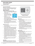
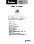
3.6
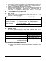
TYPICAL SYSTEM DIAGRAM
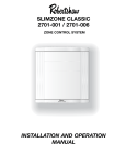
Figure 3.1 illustrates a typical SlimZone Premier installation, including the optional
environmental module (SZEM) and its accessories.
4
SlimZone Premier
OPTIONAL ACCESSORIES.
AND ACCESSORIES.
Figure 3.1: Typical System Diagram
SlimZone Premier
5
4.
SYSTEM INSTALLATION
4.1
SLIMZONE PREMIER CONTROL MODULE (SZP)
4.1.1 REMOVAL AND INSTALLATION OF THE DOOR
Installer should touch a grounded metal object before handling the control panel to avoid
potential loss of programming due to static discharge.
NOTE:
The door is hinged on the left side.
Open the door by gently pulling on the bottom right corner, applying finger pressure only. The
door may be removed once opened by applying a slight backward pressure. Replace the door
by hooking around the tabs on the left side of the backplate and snapping back into place.
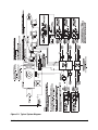
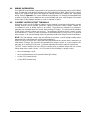
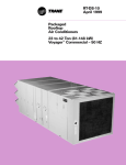
4.1.2 INSTALLATION OF THE BACKPLATE
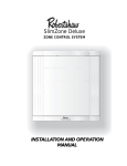
The control module can be mounted on any interior surface. Use the mounting holes on the
backplate of the main unit and the two (2) mounting holes on the expander modules (if so
equipped) to secure using the supplied #8 screws (Figure 4.1). Mount the control module in a
location that provides easy access for service. Do not mount the control module on any part
of the HVAC equipment or where moisture may be present. There are several round holes and
knock-outs for through-the-wall or surface wiring.
CAUTION:
Use proper care when removing upper or lower end cap knock-outs. Apply a
sharp rap with the butt end of a screwdriver to remove. Do not use sharp instruments to
remove the knock-outs as internal damage may occur.
SZP-3 SHOWN WITH ONE
EXPANDER MODULE (SZEX)
Figure 4.1: Mounting Holes
6
SlimZone Premier
4.2
THERMOSTAT INSTALLATION: DSL-520P
LOCATION
The most important consideration in installing your DSL-520P Communicating Zone thermostat
is where to locate the unit. The location can radically affect the operation of the thermostat.
To ensure proper operation, the thermostat should be mounted on an inside wall in a frequently
occupied area of the zone. In addition, its position must be at least 18 inches (46cm) from any
outside wall, and approximately 5 feet (1.5m) above the floor in a location with freely circulating
air of an average temperature. The control module has four (4) terminals at each zone terminal
strip for connecting the thermostat.
CAUTION: Ensure that the following polarity is respected (refer to Figure 4.2):
DSL-520P.......SZP
1 ..................... 1
2 ..................... 2
3 ..................... 3
4 ..................... 4
Refer to the manual provided with the DSL-520P thermostat for detailed instructions.
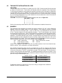
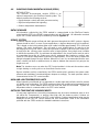
4.3
DAMPERS
Typical dampers are designed to work with low pressure systems (1.0" WC or less). Balancing
dampers should be installed ahead of all zone dampers. Zone dampers should be installed
10ft. (3m) back from discharge grille. A flex or lined duct is recommended for the last 5ft.
(1.5m). Enerstat dampers are nonmodulating dampers. Two (2) wire dampers are powered
closed and spring return open. Three (3) wire dampers are powered closed and powered open.
For applications requiring minimum air ventilation, an adjustment screw is available to set the
damper to a specified minimum open position. Enerstat dampers are shipped from the factory
with the minimum position adjustment screw in the fully closed position; allow for a 3% to 5%
leakage with damper closed. The control module has five (5) terminals at each zone terminal
strip for damper connections which are as follows (refer to Figure 4.2):
24L: 24VAC transformer,
24N: 24VAC transformer common
PC:
power damper closed
24N: common
PO:
power damper opened
Power to the dampers is provided by the 24L and 24N terminals at each zone terminal strip.
Refer to section 3.4 for information on sizing transformers.
High ambient temperatures that may be encountered (in an attic for instance), will have an
impact on the current capabilities of the panel and the number of zone dampers that can be
connected to the panel. The SZP is powered by a single 75VA transformer. This transformer is
used to power the panel and thermostats. The ambient temperature will have an impact on the
polyfuse current limiting protection. The maximum number of dampers that can be connected
per zone using Enerstat dampers are:
At 25°C (77°F)
At 40°C (104°F)
5 E Series dampers
4 E Series dampers
4 E2 Series dampers
3 E2 Series dampers
5 E3 Series dampers
4 E3 Series dampers
If additional dampers are required you must use a relay to energize these additional
dampers from an independent source.
SlimZone Premier
7
Figure 4.2: SZP Wiring Diagram
8
SlimZone Premier
EMERGENCY
SlimZone Premier
9
4.4
WIRING INFORMATION
Use #18AWG (nonshielded) copper wire for all system wiring; thermostats may use 18-24AWG
wire. Thermostats and damper actuators may be located up to 300ft. (90m) from the control
module. All system wires should be tagged to identify thermostat, damper and equipment
wiring. Refer to Figure 4.2 for control module wiring diagram. It is strongly recommended that
a spare or third wire be run between the control module and each zone damper in the event
that a three (3) wire damper actuator is used or required in future.
4.5
CURRENT LIMITED OUTPUT TERMINALS
All output circuits on the SlimZone Premier control module incorporate self-resetting current
limiting devices which provide protection against excessive current draws caused by
circumstances such as wiring shorts on an output. These devices, referred to as polyfuses,
generally are activated when the current draw exceeds 2.5Amps. The value and the duration
of the excess current is taken into account. The polyfuses will allow excess currents of very
short duration (i.e., spikes) in order to prevent circuit interruptions by noisy lines or occasional
minor surges. In its current limiting mode, the polyfuses reduce the output current to milliamps.
NOTE: The low leakage current may be sufficient to produce a small voltage reading when
measured with a volt meter with a high input impedance.
When the cause of the excess current has been removed and the current draw is returned to a
value below 2.5Amps, the polyfuse will reestablish full output current; in some instances this
may take up to twenty (20) seconds. Polyfuses eliminate the need to replace blown fuses.
The SZP control module uses red LEDs to indicate when a problem exists with the current
being drawn from certain circuits. An LED exists for the following on-board circuits:
10
•
each zone damper circuit
•
each zone thermostat circuit (current limited @ 0.1Amp)
•
on the COOL terminal strip
•
on the HEAT terminal strip
SlimZone Premier
4.6
SLIMZONE ENVIRONMENTAL MODULE (SZEM)
INTRODUCTION
The SlimZone Environmental module (SZEM) is an
optional component in the SlimZone Premier system. The
module provides the following services:
• Bypass damper control and static pressure sensing
• High/Low temperature limit signaling
• Outdoor temperature measurement
DATA EXCHANGE
All information collected by the SZEM module is communicated to the SlimZone Premier
control module (SZP) via a RS485 communication port at 1200 baud. All information received
by the SZP control module may be viewed by the user (Figure 5.2).
BYPASS SYSTEM
In order to maintain proper air flow and static pressure throughout the HVAC system, a bypass
system should be used. In some 2-zone applications, a bypass damper may not be required.
This is based on duct sizing where either zone is able to handle approximately 75% of the total
system CFM (cubic feet/minute). This will result in only slightly higher air velocity at the
discharge grille if only one zone is calling and yet allow for proper CFM across the cooling coil.
A single zone fan call may cause some air noise in large systems. If any single zone is unable
to handle the remaining 25%, the minimum air adjustment in the closed zones must be set to
accommodate the excess air. Single zone calls for equipment (fan, heating or cooling), may
cause air noise and/or temperature overshoot in large systems. This is the result of excess air
being discharged through the zone diffuser. When this occurs it is recommended that the user
select a similar call from an additional zone in order to alleviate the amount of air going to the
single zone call.
Note: This situation can occur when the SZP Control module is in the auto fan mode or when
a single heating or cooling call occurs from Must-Service zones.
Bypass activities are fully controlled by the SZEM module which monitors the system static
pressure and modulates a motorized bypass damper accordingly. The static pressure value is
communicated to the SZP control module.
HIGH AND LOW TEMPERATURE LIMITS
When bypassing conditioned air it is important to consider high and low limit control to prevent
coil freeze up or overheating. The SZEM module monitors the conditioned air temperature and
signals the SZP control module when the high and low limits are exceeded. System air
temperature value is communicated to the SZP control module.
OUTDOOR TEMPERATURE MEASUREMENTS
In heat pump applications, the outdoor temperature may be used to determine when to lock
out either the compressor(s) or auxiliary heat (high and low balance points). Outdoor air
temperature is communicated to the SZP control module. Outdoor temperature value may be
displayed at both the SZP control module and zone thermostats. Refer to the information
provided with the SZEM module for detailed installation instructions.
SlimZone Premier
11
5.
5.1
SYSTEM OPTIONS AND OPERATION
INTERACTION BETWEEN MODULES
The SZP control module is the central processing unit in the SlimZone Premier system and is
in constant communication with the DSL-520P zone thermostats and the optional SlimZone
Environmental module (SZEM). The following describes the interaction between the modules.
5.1.1 SZP CONTROL MODULE
The control module has global control of the system and establishes parameters such as
program temperature setpoints, schedules, and mode of operation.
EQUIPMENT CONTROL
The control module has full control of the HVAC equipment. It processes the zone requests for
heating, cooling, and fan and monitors the conditions reported by the SZEM module and
services the zones accordingly.
TESTING
All relay output terminals may be tested from the SZP control module via the Equipment Test
menu. All zone dampers may be activated as well as all zone perimeter heat relays. Bypass
dampers may also be tested from the control module.
PROGRAMMING
All system programming is done at the SZP control module. The module establishes the
temperature setpoints and the events the zone thermostats control. Temporary local override
is made possible by changing the setpoints at the zone thermostats. Refer to section 5.2 for
further programming information.
MODE OF OPERATION (Off, Cool, Heat, Auto, E Heat)
The control module establishes the global (system) mode of operation; local mode of operation
may be selected at the zone thermostats. Only calls for the modes established by the control
module will be serviced.
CONSTANT FAN
Global fan control is established at the control module. When set to constant fan (fan on) and
the system is idle, all zone dampers are opened to circulate air to all zones. When the global
fan control is set to auto, local requests for constant fan are serviced; dampers to zones not
calling for constant fan are closed. The G1 terminal is used for constant fan. Refer to section
5.4 for Smart Fan feature.
MINIMUM EQUIPMENT ON AND OFF TIMES (Short Cycle Protection)
Minimum equipment ON and OFF times are set at the control module for both heating and
cooling. Zone thermostats also have minimum ON time settings (2 or 4 minutes). The control
module ensures the equipment is not shut off until the thermostat and the module minimum ON
times have elapsed; timers run concurrently. Minimum OFF time is established by the control
module.
DATA EXCHANGE: SZP CONTROL MODULE / DSL-520P ZONE THERMOSTAT
The SZP control module provides the following information to the DSL-520P thermostats:
• temperature setpoints
• event (morning, day, evening, or night)
• time of day
• outdoor temperature (if SZEM module is installed with this option)
12
SlimZone Premier
The DSL-520P thermostat provides the following information to the SZP control module:
• heating, cooling, and fan requirements
• room temperature
• temperature setpoints (if temporary local override is requested)
DATA EXCHANGE: SZP CONTROL MODULE / SZEM MODULE
The SZP control module provides the following information to the SZEM module:
• high and low temperature limits
The SZEM module provides the following information to the SZP control module:
• outdoor temperature
• duct temperature and pressure
• status of high and low limits
5.1.2 DSL-520P ZONE THERMOSTAT
The DSL-520P zone thermostat provides local control of the following parameters:
MODE OF OPERATION
Local mode settings are requests only; calls for these modes are serviced only if the control
module is in that mode as well.
PERIMETER HEAT
When the SZP control module is unable to service a zone requesting heating because it is
currently servicing cooling or in a minimum OFF time, the thermostat will close its relay contact
on terminals R and W1 which may be used to energize a local perimeter heat device. When the
module is finally able to provide heating, perimeter heat will be disabled.
NOTE:
- Perimeter heat is allowed only when the control module is in the heat or auto mode.
- The perimeter heat relay is a 24VAC dry contact output (rated at 0.75Amps).
CONSTANT FAN
When global constant fan is selected, all zones are in the constant fan mode regardless of the
local fan setting. The fan (
) symbol appears on the thermostat display when local constant
fan is selected; it does not appear when global constant fan is selected.
TEMPORARY TEMPERATURE OVERRIDE
During the occupied period, individual zone temperature setpoints may be changed and remain
valid for the duration of the occupied period. The temporary setpoints are discarded when the
thermostat changes over to the unoccupied period (minimum one (1) hour).
During the unoccupied period, individual zone temperature setpoints may be changed and
remain valid for a period of one (1) hour, after which the temporary setpoints are discarded.
UNOCCUPIED MODE: SYSTEM & LOCAL
System:
Unoccupied Mode: Unoccupied mode occurs when all zone thermostats are in night mode.
Local:
Unoccupied Mode: Unoccupied mode occurs when a zone thermostat goes into night mode.
The minimum temporary override is (1) one hour and will remain in effect until the (1) one hour
period has elapsed. Moving into an unoccupied period (night mode) during this minimum
temporary override will not affect its status.
During the unoccupied period, zones 1 to 13 act as Must-Service zones when the zone
thermostat or buttons (system override) are depressed. Zones 14 to 19 do not act as
Must-Service zones at this time.
SlimZone Premier
13
MINIMUM EQUIPMENT ON TIME (short cycle protection)
The minimum amount of time the thermostat will call for heating or cooling may be set to either
2 or 4 minutes via switch #1 on the back of the thermostat. This timer is initiated the moment
the request is made, regardless if the control module services the demand immediately. When
equipment is activated, it will not shut off until both the thermostat’s and the SZP control
module’s minimum ON times have elapsed; timers run concurrently.
The thermostat has no minimum OFF time setting.
CLOCK DISPLAY FORMAT
Time may be displayed in either 12 or 24 hour format. Press and hold the FAN button, then
press the OUTDOOR button to change the format.
TEMPERATURE DISPLAY FORMAT
The temperature may be displayed in either °C or °F format. Press the and buttons
simultaneously to change the format.
5.1.3 SZEM ENVIRONMENTAL MODULE
The SZEM module monitors the system ductwork pressure and controls a motorized bypass
damper accordingly. The module also monitors the ductwork air temperature and signals the
SZP control module when the high and low limits have been exceeded. The SZEM module can
also be installed with an outdoor temperature probe. The outdoor temperature is
communicated to the SZP module.
5.2
SYSTEM PROGRAMMING
All system programming is done at the SZP control module.
5.2.1 PROGRAMMING FEATURES
The SlimZone Premier system offers the following programming features:
•
7 day programmable
•
2 or 4 events per day (morning, day, evening, night)
•
individual zone schedules
- zones 1 - 12 may have unique schedules
- zones 13 - 19 use the same schedule
•
copy a day schedule to consecutive days or to all days of the week
•
copy a zone program to other zones
5.2.2 SCHEDULES
The SZP control module can execute the schedules as follows:
NORMAL:
The control module executes the programmed schedules normally.
SUSPENDED: PERMANENTLY
When this mode is selected, the programmed schedules are disregarded and the user must
enter override temperature setpoints to which all zone thermostats will be controlling. Local
override is still allowed but for a duration of one (1) hour (unoccupied mode). The system will
remain in the PERMANENTLY SUSPENDED mode until the user changes it.
SUSPENDED: TEMPORARILY (UNTIL)
When this mode is selected, the programmed schedules are disregarded and the user must
enter override temperature setpoints to which all zone thermostats will be controlling. The time
and date when the system is to return to the NORMAL mode also must be entered. Local
14
SlimZone Premier
override is still allowed but for a duration of one (1) hour (unoccupied mode). The system will
remain in the TEMPORARILY SUSPENDED mode until the programmed time and date is
reached.
5.2.3 FACTORY DEFAULTS
The SZP control module is shipped with the following program settings:
• All temperature setpoints set at: ...Heat: 68°F(20°C)
Cool: 73°F(23°C)
• All schedule times set at: ..............12:00A
5.3
USER OPTIONS
The SZP control module allows the user to set the time of day display in 12 or 24 hour format.
The user also may set the temperature display in Celsius or Fahrenheit. These settings do not
affect the thermostat displays.
5.4
HVAC OPTIONS
The SZP control module allows the installer to establish the following system parameters:
HEAT/COOL OR HEAT PUMP SYSTEM
The SZP module can control up to four (4) stages of heating and three (3) stages of cooling in
the heat/cool mode and three (3) stages of heating and three (3) stages of cooling in the heat
pump mode.
In the heat pump setup, W3 terminal is used for the auxiliary heat, even when a single
compressor is used. The emergency heat mode becomes available as one of the modes of
operation. When emergency heat is selected, W3 terminal will cycle on demands for heating
and W4 terminal will be on continuously.
NUMBER OF STAGES OF HEATING AND COOLING AND NUMBER OF ZONES REQUIRED
TO ACTIVATE EACH STAGE
Upstaging and downstaging is based strictly on the number of zones calling. Downstaging will
also occur when the high and low limits are exceeded.
MINIMUM HEATING AND COOLING ON AND OFF TIMES
The system allows input of different minimum ON and OFF times for heating and cooling.
CONTROL METHOD: TIMESHARE OR DIFFERENTIAL
The SZP control module has two methods of determining which equipment calls to service first
(heating or cooling) and when to changeover to the opposite equipment. The two control
methods, timesharing and differential, are described in section 5.5.
THE MUST-SERVICE ZONE
The Must-Service zone uses an intelligent weighting protocol which gives a status to the zone
such that a call from this zone equals the number of zones required to activate the first stage
of that mode. For example, if three (3) zones are required to call for activating first stage
heating, a call from the Must-Service zone will be given a weight of three (3) to simulate three
(3) zones calling. From this point, the control module will process this call and determine if the
zone is to be serviced based on the timesharing or differential control methods. The MustService zone is not given any other special status.
HIGH AND LOW TEMPERATURE LIMITS
The limits are entered at the SZP control module and stored in the SZEM module memory.
HIGH AND LOW BALANCE POINTS
These values are used to determine when the auxiliary heat terminal should be disabled (high
balance point) and when the compressor terminal should be disabled (low balance point).
SlimZone Premier
15
SMART FAN ENABLE
When Smart Fan is enabled and constant fan is selected at the control module (global constant
fan), the fan will remain ON during the occupied period and go to the auto mode during the
unoccupied period. Note that all zones have to be in the unoccupied (night) period for the fan
to go in the auto mode. If auto fan is selected at the control module, local fan demands are
processed normally; fan will be ON to zones requesting constant fan.
5.5
CONTROL METHODS
5.5.1 TIMESHARE
The timeshare control method will change over from heating to cooling and vice versa as
follows:
A.
No equipment calls are serviced until the number of zones calling for either heating or
cooling meet the requirements for the number of zones needed to activate first stage. The
first mode to satisfy the requirements will be serviced.
B.
Upon initiating the equipment call, the control module starts a 20 minute internal timer.
Calls for the opposite equipment mode are ignored during these 20 minutes.
C.
If the current call is not satisfied after the first 20 minutes and calls for the opposite
mode have met the requirements to activate the first stage of equipment, the control
module will changeover to the opposite mode and reinitiate the 20 minute timer.
NOTE:
- In heat/cool mode, the control module will changeover to the opposite equipment
mode after the minimum OFF time of the equipment it just serviced.
- In heat pump mode, changeover is done by activating the opposite reversing valve
output (O/B terminals); the compressor is not turned OFF.
D.
The control module will continue in this fashion, changing over every 20 minutes, until the
zones are satisfied. Note that the control module will service an equipment call only if the
number of zones calling meet the requirements to activate that stage. The moment the
number of zones calling is not sufficient to activate that stage, the module will consider
this call to be satisfied.
UPSTAGING AND DOWNSTAGING
When the control module changes over to the opposite equipment mode and sufficient number
of zones are calling for second stage, the module will start with the first stage. If after 5 minutes
the number of zones calling is still sufficient, the module will activate the second stage.
Subsequent stages are activated, one every 5 minutes, providing the number of zones calling
is sufficient. In the heat pump mode, the auxiliary heat is delayed a further 15 minutes after the
last compressor stage.
Downstaging occurs in a similar manner when the number of zones calling decreases to a value
below the number of zones required to activate that stage.
5.5.2 DIFFERENTIAL
In the differential control method, the control module determines the difference between the
number of zones calling for heating versus the number of zones calling for cooling. The
difference calculated is then compared to the number of zones required to activate the first
stage of equipment for the mode which has more calls, and if sufficient, that stage will be
activated and zones calling for that mode will be serviced.
UPSTAGING AND DOWNSTAGING
If the calculated difference between zone calls is sufficient to activate the second stage of
equipment for the mode currently activated, then the module will upstage. Downstaging occurs
when the number of zones calling decreases and the calculated difference falls to a value below
the number of zones required to activate that stage.
16
SlimZone Premier
5.6
SEQUENCE OF OPERATION
5.6.1 TIMESHARE MODE
Note: The following assumes the control module is in the auto mode of operation.
A.
Control module receives zone requests for heating and cooling. First mode to satisfy the
number of zones requirement for first stage is serviced.
B.
Equipment is activated:
- W1 is energized for heating and Y1 is energized for cooling (in both heat/cool and heat pump
mode).
- B terminal is energized for heating and O terminal is energized for cooling.
- Both G1 & G2 fan terminals are energized.
- Dampers to zones calling for that mode are open.
- 20 minute timer is initiated.
C.
Equipment stays ON for at least minimum ON time.
D.
In the heat pump mode, if the 20 minute timer runs out and the opposite mode is being
requested, the control module will changeover to the opposite mode (timesharing) by toggling
the reversing valve output terminals (O and B). The compressor is not turned OFF.
E.
When the equipment call is satisfied (in both heat/cool and heat pump mode), or when the 20
minute timer has elapsed and the opposite mode is being requested (in heat/cool mode), the
equipment is turned OFF and a 45 second purge cycle begins:
- W1 or Y1 is deenergized.
- G2 is deenergized; G1 remains energized.
- B or O terminal remains energized.
- Zone dampers remain open.
F.
After the 45 second fan purge, the equipment will remain OFF for at least the duration of the
minimum OFF time for the equipment which was just serviced. The control module will remain
in one of the following conditions during this period:
- If global constant fan selected, all zone dampers open and G1 remains ON to circulate air.
- If only local constant fan is requested, dampers to zones requesting constant fan open and
all other dampers close. G1 remains ON.
- If constant fan not requested and no other equipment calls are present, G1 is deenergized and
dampers to last zones calling remain open.
- If constant fan is not requested and calls for the opposite mode of equipment are received by
the module, G1 is deenergized and dampers to the zones calling for the opposite mode are
open and all other dampers are closed.
G.
After the minimum OFF time, the control module will service the opposite mode of equipment
if calls for it are pending; steps A to E are repeated. If there are no pending calls for the
opposite mode, the control module is ready to service any calls.
NOTES:
• When changing over to the opposite mode of equipment, the control module will start with
the first stage of equipment even if enough zones are calling to activate additional stages.
The module will upstage every five (5) minutes afterwards; auxiliary heat stage in the heat
pump mode will energize fifteen (15) minutes after the last compressor stage.
SlimZone Premier
17
•
If the control module receives a high limit (in heating) or low limit (in cooling) alarm from the
SZEM module, it will downstage the equipment, one stage immediately then one stage
every five (5) minutes, until either the alarm condition is resolved or until equipment is shut
off. The control module will not reactivate the equipment until the alarm conditions are
corrected.
•
If the smoke detector terminals close, the control module will immediately shut OFF the
equipment and energize the close damper terminals.
5.6.2 DIFFERENTIAL MODE
A.
In the differential mode, equipment stages are activated based strictly on the number of zones
calling.
B.
Activating equipment and turning it OFF is same as in the timeshare mode.
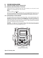
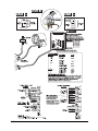
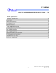
5.7
USER INTERFACE
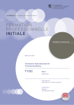
The SZP control module incorporates a
four (4) button keypad and four (4) lines
by twenty (20) characters Liquid Crystal
Display (LCD) providing the most
advanced and user friendly interface in
the industry. All system information and
commands are entered and may be
viewed via this interface.
White lines indicate
which LCD line
each button
corresponds to
Figure 5.1: User Interface
The control module incorporates Light Emitting Diodes (LEDs) to indicate the status of certain
parameters such as the following:
• Damper open (labeled D - green)
• Fault in wiring (labeled F - red)
• Zone thermostat calls for heating (labeled W - orange)
• Zone thermostat calls for cooling (labeled Y - yellow)
• Zone thermostat calls for fan (labeled G - green)
• Heating equipment output terminals energized (labeled W1 - W4 and B - orange)
• Cooling equipment output terminals energized (labeled Y1-Y3 and O - yellow)
• Fan output terminals energized (labeled G1 & G2 - green)
• Proper communication between thermostats and SZP module (labeled Normal When
Flashing - green)
• Proper communication between SZEX expander modules and SZP module (labeled Module
Connected - green)
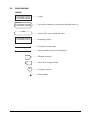
5.7.1 LCD SYMBOL DESCRIPTION
■
●
18
Leads to other menus; further data to be entered; further options available
Toggles between menu selections or options
Forward to next menu
Backs up to previous screen or data entry completed for menu path currently in use
Increase value of an item
Decrease value of an item
SlimZone Premier
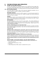
5.8
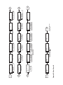
FLOW DIAGRAM
LEGEND
01234567890123456789
01234567890123456789
01234567890123456789
01234567890123456789
May select:
012345678901234567890
012345678901234567890
.......... Screen
.......... Lists options selected by pressing the indicated button #
Actions
.......... Actions which occur behind the scene
01234567890123456789
01234567890123456789
.......... Momentary screen
.......... Direct path to next screen
.......... Path to available options to be displayed
.......... Off-page connector
.......... Return from off-page screens
B
.......... On-page connector
1 .......... Button number
SlimZone Premier
19
1
1
2
3
2
Figure 5.2: Flow Chart- A
3
Options
Schedule: Suspended
Programming
4
12:00A Fri Jan01/99
Auto Mode
Fan Auto
Schedule: Normal
4
MAIN
SCREEN
4
4
4
1
4
Program Zone
Copy Zone Program
2 Events/day
4
Schedule: Normal
1
1
Schedule: Suspended 4
Permanently
2
May select the following:
12 Hour Clock
24 Hour Clock
3
4
4
4
4
4
3
Copying
Copy Zone #01
To Zone #02
Do Copy
Zone # 01
4
Temperature
Heat 10
Cool 30
1
2
3
4
3
2
4
4
4
4
3
4
06:00A
Wed
1
4
1
2
B
4
3
2
1
4
Zone #01
Exercise Damper
Perimeter Heat
2
Bypass setup
Step 06
Wait 30
Copy to consecutive
Copy to all days
4
4
Copies the schedule to all
days of the week.
Morning
Set Temperature
Heat 10 Morning
Cool 30
Toggles Bypass damper
position to:
Bypass - Open
Bypass - Close
Bypass - Normal
3
Outdoor 73 Duct 74
Pressure 0.03 in. WC
Bypass - Normal
Zone #01 Room 76
Heat 68 Cool 70
Auto Mode
Calls: Cool
C1
C
No
Are you sure ?
Yes
A3
A
2
Zone # 01
Set Temperatures
Set Schedule
1
Hold 1 for 10 seconds
to unlock screen.
Equipment
Zone Module
Environmental
1
Setup
Panel
Bypass
12:00A Fri Jan 01/99
4
May select the following:
2 Events/day
4 Events/day
3
2
For HVAC Techs Only!
Setup
Equipment Test
Locked
Schedule: status
Heat Calls: # of zones calling
Cool Calls: # of zones calling
System mode
Duct temperature
Outdoor temperature
Duct pressure
May select the following:
Degrees C
Degrees F
1
Schedule: Suspended 3
Until
12:00 Fri Jan01/99
3
2
HVAC options
Degrees C
12 Hour Clock
May select the following:
Fan Auto
Fan On
May select the following:
System Off
Cool Mode
Heat Mode
Auto Mode
EHeat Mode
12:00A Fri Jan01/99
Line #4 of the main Screen scrolls the following
information:
(NOTE: Duct and outdoor information are only
displayed if SZEM module connected)
4
3
Copies the schedule up to
the day selected, and
increments the days.
Do Copy
Wed up to Thu
Off
Perimeter Heat #01
Damper #01
Open
B
2
Equipment Relay
W4 Off
W3 Off
W2 Off
W1 Off
Y3 Off
Default:
Range:
4
4
Default:
Range:
-55
Press any button marked to turn
equipment relays ON or OFF.
Y2 Off
Y1 Off
G2 Off
-55° to 54°F
(-48° to 12°C)
-55°F (-48°C)
Low Balance:
May select:
2 - 8 minutes
Minimum Heat Off
Time:
02 (minutes)
Up to 4 stages in Heat/Cool
Up to 3 stages in Heat pump
02
# of Heat Stages:
Only appears when
Heat pump selected.
-01° to 119°F
(-18° to 48°C)
108°F (42°C)
108
Select 1 of any
of the 19 zones
High Balance:
May select:
2 - 8 minutes
Minimum Heat On
Time:
02 (minutes)
Only appears when
Heat pump is selected
Add-on Heat pump?
NO
None
4
4
Must Service Zone
Appears for each #
of stage selected.
Cool Calls Needed
for Stage 01
May select:
Heat pump
Heat/Cool
System Type:
Heatpump
Figure 5.3: Flow Chart- B
C
A2
A1
A
4
4
Minimum Cool On
Time:
05 (minutes)
G1 On
O On
B Off
Default:
Range:
148
75° to 195°F
(24° to 91°C)
148°F (64°C)
High Limit
May select:
2 - 8 minutes
4
Heat Calls Needed
for Stage 02
4
21° to 57°F
(-06° to 14°C)
30°F (-01°C)
Turns relays off when this
section is exited
C1
Default:
Range:
30
Low Limit
May select:
2 - 8 minutes
Minimum Cool Off
Time:
05 (minutes)
Appears for each #
of stage selected.
Heat Calls Needed
for Stage 01
4
4
2
Smart Fan?
No
May select:
Timeshare
Differential
Control Method
Timeshare
Up to 3 stages in Heat/Cool
Up to 3 stages in Heat pump
01
# of Cool Stages:
4
4
A3
A2
A1
6.
START UP AND TEST
SETUP
A. Check that the SZEM Environmental module and its components are properly installed.
B. Check all zone thermostats and dampers for proper installation.
C. Ensure polarity has been respected for all zone thermostat wiring and for the SZEM module.
D. Ensure all wires are properly inserted and screwed down in terminal blocks.
E. Tag all wiring and system components to correspond to the zone they serve.
F.
If HVAC unit incorporates an economizer, it is important that it be checked for proper
operation and that the minimum positioning stop be set.
G. If the HVAC unit has an economizer that is not equipped with a relief damper, it may be
necessary to relink the return air damper so that it will always remain thirty percent (30%)
open, otherwise the bypass damper system may not perform properly.
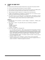
START UP
A. Disconnect RC and RH terminals to prevent damage to equipment.
functionality first.
Establish panel
B. Apply 24VAC to system. The system will power up in the following configuration:
- Auto mode
- Fan auto
- Schedule: Suspended
- Heat/Cool system
- 1 Heat / 1 Cool stages
C. Observe the condition of the following LEDs:
22
•
W, Y, & G lights at zone inputs. LEDs to any zone input with a thermostat connected
must not be all ON; if they are, panel and thermostat are not communicating. Check
wiring for proper polarity. If a thermostat is not connected, these LEDs will be all ON.
NOTE: When proper communication is established, the satellite dish symbol (&) should
appear on the thermostat LCDs and the uplink symbol (') should flash occasionally.
•
On the SZEX Expander modules, the NORMAL WHEN FLASHING is flashing and the
MODULE CONNECTED is ON.
•
Equipment outputs are not conflicting (i.e., W and Y LEDs not ON at same time).
NOTE: On initial power up, the control module will not respond to equipment calls for a
period of 4 minutes. Constant fan requests are serviced.
SlimZone Premier
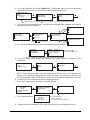
D. Go to the Equipment Test screen (Figure 5.2). Following the menus, turn each equipment
output relay ON and OFF to check that on-board relays are functional.
For HVAC Techs Only!
Setup
Equipment Test
Locked
Equipment
Zone Module
Environmental
3
1
Equipment Relay
W4 Off
W3 Off
4
Note: Must hold button 1 for 10 seconds to unlock these menu options.
E. Go to the Zone Module test screen. Activate all zone dampers and perimeter heat relays (if
perimeter heat option installed).
Damper #01
Open
2
Equipment
Zone Module
Environmental
2
Zone #01 Room 76
Heat 68 Cool 70
Auto Mode
Calls: Fan
1
Zone #01
Exercise Damper
Perimeter Heat
Perimeter Heat #01
Press
or
3
to select zone
Off
F. Go to the Environmental test screen and activate the bypass damper.
Equipment
Zone Module
Environmental
3
Outdoor
73 Duct 74
Pressure 0.03 in. WC
Bypass - Normal
Press button 3 to
toggle damper position
NOTE: Leave the bypass damper closed at this stage.
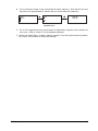
G. Go to the Panel Setup screen and configure the control module according to your
installation.
For HVAC Techs Only!
Setup
Equipment Test
2
Setup
Panel
Bypass
2
System Type:
Heat pump
4
Refer to Figure 5.3
NOTE: During the panel setup, you must select a Must-Service zone. An equipment call
from this zone is given enough weight to activate first stage. You may want to select a zone
at close proximity to the panel during the system test to facilitate the equipment cycle test.
H. Connect RH & RC terminals to power the equipment relays.
I. Go to the Schedule menu and select Schedule: Normal.
12:00A Fri Jan01/99
System Off
Fan On
Schedule:Suspended
Suspended
4
Options
Schedule: Suspended
Programming
Schedule: Normal
2
Press 1 until Normal is selected
J. Go to the Main Menu:
12:00A Fri Jan01/99
System Off
Fan On
Schedule: Normal
Select the following:
- System Off mode
- Fan On to enable constant fan
K. Observe that all zone damper LEDs come ON and that all zone dampers are open.
SlimZone Premier
23
L. Heating cycle:
• Place the system in the heat mode.
•
Bring the heating setpoint of the Must-Service zone to its highest setting.
•
Observe that the W LED at the zone input on the control module comes ON.
•
Observe that the following equipment terminals are activated and that LEDs come ON:
- W1 (first stage heat)
- B (continuously energized in heating)
- G1 and G2 (fan relays)
- Zone damper LED of the zone calling comes ON, all others turn OFF
•
Activate additional heat stages, if preferred, by making sufficient additional thermostats
call for heating.
•
Return thermostat(s) to their original setpoints. Heating equipment will turn OFF after
the minimum ON time. Observe the following:
- W1 (and any additional stages) LED turns OFF
- G2 LED turns OFF
- G1 LED and zone damper(s) remain ON for the 45 second fan purge
- After the 45 second fan purge, G1 LED remains ON and all zone dampers open
M. Cooling cycle:
• Place the system in the cool mode.
24
•
Bring the cooling setpoint of the Must-Service zone to its lowest setting.
•
Observe that the Y LED at the zone input on the control module comes ON.
•
Observe that the following equipment terminals are activated and that LEDs come ON:
- Y1 (first stage heat)
- O (continuously ON in cooling)
- G1 and G2 (fan relays)
- Zone damper LED of the zone calling comes ON, all others turn OFF
•
Activate additional cool stages, if preferred, by making sufficient additional thermostats
call for cooling.
•
Return thermostat(s) to their original setpoints. Cooling equipment will turn OFF after
the minimum ON time. Observe the following:
- Y1 (and any additional stages) LED turns OFF
- G2 LED turns OFF
- G1 LED and zone damper(s) remain ON for the 45 second fan purge
- After the 45 second fan purge, G1 LED remains ON and all zone dampers open
SlimZone Premier
N. Go to the Bypass Setup screen and initiate the setup sequence. Note that this process
may take up to approximately 5 minutes and you cannot abort this sequence.
Setup
Panel
Bypass
3
Are you sure ?
Yes
No
2
Bypass setup
Step 06
Wait 30
You may abort the
sequence here.
O. Go to the Programming menu and program all temperature setpoints and schedules for
each zone. Refer to section 5.2 for programming features.
P. Return to the Main Menu. System is ready to operate. Place the system mode of operation,
fan control, and schedule to the desired settings.
SlimZone Premier
25
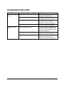
TROUBLESHOOTING GUIDE
PROBLEM
No heat/cooling in
house
POSSIBLE CAUSE
Zone thermostat(s)
Faulty heating /cooling equipment
Faulty thermostat
Faulty zone control panel
No heat/cooling in
zone
Balancing damper closed
Zone registers closed
Faulty thermostat
26
SOLUTION
Select heat, cool or auto mode
of operation at thermostat
Troubleshoot equipment according
to manufacturer’s instructions.
Refer to instructions provided with
the thermostat for verifying
operations. Replace if necessary.
Follow instructions outlined in Setup
and Test. Replace if necessary.
Check all balancing dampers in the
same duct as the motorized zone
damper; closed balancing dampers
should be readjusted.
Check all zone registers; closed
registers should be readjusted.
Refer to instructions provided with
the thermostat for verifying
operations. Replace if necessary.
SlimZone Premier
GLOSSARY
Auxiliary/Emergency
Heat
Applicable to heat pump systems only. Auxiliary heat refers to the 3rd heat
stage (W3). In the event of a heat pump compressor failure Emergency Heat (EH)
is activated via the user interface on the control module which disables the
compressor stages and cycles W3 on all heat calls; W4 is continuously ON in
this mode. Refer to section 5.6 for sequence of operation.
Bypass System
A Bypass System maintains a uniform amount of airflow in the branch ducts
by opening and closing a damper blade in the main supply duct.
Event
Up to four (4) events per day: morning , day , evening , and night .
Each event includes temperature setpoint values for heating and cooling and
the schedule at which time each event begins.
Fuzzy Logic
The method by which the thermostat determines the load within its zone
before communicating the zone requirements to the SZP module.
Modes
A mode is a specific operating setting (Off, Cool, Heat, Auto, E Heat) which
can be established at the control module and the zone thermostats.
Polarity
Correct polarity must be maintained between the communicating zone
thermostats and the SZP module to ensure accurate communication and
avoid damage. Polarity must be 1-1.
Program
Programming is done at the SZP module and establishes the temperature
setpoints and events that the zone thermostats control.
Schedule
A Schedule refers to the programmed times for which events are to occur
during a 24 hour period.
SL-IDS
Slimline Indoor Remote Sensors
Stages
The way increments of heating or cooling are controlled. The SZP module
allows for four (4) stages of heating and three (3) stages of cooling with a
heat/cool system and three (3) stages of heating and three (3) stages of cooling
with a heat pump system.
SZEM
Slimzone Environmental Module
SZEX
Slimzone Expander Module
SZP
Slimzone Premier Control Module
Zone
A defined area that is controlled by a DSL-520P zone thermostat and
motorized zone damper. Zone thermostats request heating or cooling
from the SZP Control module, which in turn controls the HVAC equipment
and zone dampers accordingly.
SlimZone Premier
27
APPENDIX A: List of Figures
FIGURE 3.1: TYPICAL SYSTEM DIAGRAM....................................................................................................5
FIGURE 4.1: MOUNTING HOLES ...................................................................................................................6
FIGURE 4.2: SZP WIRING DIAGRAM .............................................................................................................8
FIGURE 5.1: USER INTERFACE ...................................................................................................................18
FIGURE 5.2: FLOW CHART - A ....................................................................................................................20
FIGURE 5.3: FLOW CHART - B ....................................................................................................................21
APPENDIX B: List of Tables
TABLE 3.1: SLIMZONE PREMIER BASIC COMPONENTS ............................................................................3
TABLE 3.2: SLIMZONE EXPANDER MODULE COMPONENTS .....................................................................3
TABLE 3.3: SLIMZONE ENVIRONMENTAL MODULE COMPONENTS ..........................................................4
28
SlimZone Premier
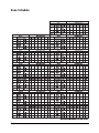
Zone Schedule
SlimZone Premier
29
SLIMZONE PREMIER-SZP-ZONE DIAGRAM
30
SlimZone Premier
WARRANTY
Limited One Year Warranty
Robertshaw warrants to the original purchaser that its product and component parts will be free from
defects in workmanship and materials for a period of one year from the date of purchase. Your dealer
will provide free replacement of your thermostat upon proof of purchase.
Exclusions
This warranty does not apply in the event of misuse, abuse or as a result of unauthorized alterations or
repairs. The manufacturer will not be liable for any consequential damages including, without limitation,
damages resulting from defects, loss of use, or misuse.
Compliance
•
This equipment, if installed in strict accordance with the manufacturer's instructions, complies with the
limits for a Class B computing device pursuant to Subpart J of Part 15 of FCC rules.
•
This equipment, if installed in strict accordance with the manufacturer’s instructions, complies with CE
rules.
SlimZone Premier
31
™
SlimZone Premier
Uni-Line North America
P.O. Box 2000
Corona, CA 92879-1736
United States of America
Canadian Division
5785 Kennedy Road
Mississauga, Ontario L4Z 2G3
Canada
Telephone +1 909 734 2600
Fax
+1 909 737 8261
Telephone +1 905 890 5811
Fax
+1 905 890 6098
110-908C