1
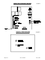
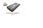
Doc - 6001020
Rev - 3052
INSTALLATION INSTRUCTIONS
FOR ALL
SPECTRUM, VISTA, AND REGENCY
TELEPHONE ENTRY SYSTEMS
WITH THE -99 BOARD
SENTEX SYSTEMS, INC.
CHATSWORTH, CALIFORNIA
ARRANGING FOR PHONE LINE INSTALLATION
You or your customer should have the telephone company install a line as close as possible to the
location of the Sentex telephone entry system. The telephone company will require the following information to
install the line:
FCC REGISTRATION NUMBER:
RINGER EQUIVALENCE NUMBER (REN):
TYPE OF CONNECTOR (JACK):
DS86W6-70754-AL
0.0B
USOC RJ11C
WARNING
IMPROPER POWER TO SYSTEM AND/OR INADEQUATE GROUNDING
MAY CAUSE SYSTEM MALFUNCTIONS. FOLLOW THESE INSTALLATION
INSTRUCTIONS CAREFULLY. DO NOT USE THE POWER
TRANSFORMER TO POWER ANYTHING OTHER THAN THE SENTEX
UNIT. ALSO, DO NOT USE TOO LIGHT OF A GAUGE OF WIRE BETWEEN
THE TRANSFORMER AND THE SENTEX UNIT. ENSURE POWER, AT
POWER TEST POINT AS IT IS SPECIFIED IN THIS MANUAL. DO NOT
RUN 110V INSIDE THIS ENCLOSURE.
PULLING WIRES
The following cabling must be run to the location at which the telephone entry system will be mounted:
1.
A 2 conductor, 20 to 24 awg cable from the jack installed by the telephone company.
2.
A 2 conductor, 12 to 18 awg cable from the location of the 120 VAC outlet into which you will plug
either the 12 VAC, 20 VA transformer supplied by Sentex or a 13.5 VDC power supply that you
supply. See the table below for wire sizes and distances.
DC POWER
WIRE SIZE
18 AWG
18 AWG
14 AWG
12 AWG
10 AWG
DISTANCE
30' and under
30'-75'
75'-150'
150'-250'
250'-500'
AC POWER
WIRE SIZE
18 AWG
14 AWG
12 AWG
10 AWG
-----
Table 1 - Power Wire Distance
3.
Rev. #: 3052
A 2 conductor cable from the door strike, magnetic lock, or gate operator. You may also run power
for the door strike or magnetic lock into the system if you desire (see selection on page 3 titled
"MAKING BASIC CONNECTIONS" for details on how these wires will be connected) or connect
power to the strike/lock outside of the cabinet.
Doc. #: 6001020
Page 1 of 6
MOUNTING THE CABINET
1. Determine which of the two "knock-outs" that provide access into the box (back and bottom) you will use.
2. Carefully remove the plug from the opening to be used. You may wish to remove the circuit board(s) from
the cabinet before knocking out the plug, but it is not always necessary to do so. If you do remove the circuit
boards, you will have to disconnect the keypad from the circuit board. IMPORTANT NOTE: Do not grab the
keypad connector directly when trying to remove it from the socket on the main board or you may break one
of the pins on the connector. Instead, grab the ribbon cable just below the connector, put your thumb over
the connector and gently rock it from side to side while pulling the cable away from the board.
3. Mount the unit on the wall. Put the top two screws/bolts into the wall, but leave them loose. Hang the
cabinet on them by inserting them into the larger part of the top two openings and then lowering the cabinet.
Then put the bottom two screws/bolts into the wall through the bottom two openings. Tighten down all four
screws/bolts.
4. Pull all of your wires into the cabinet (if you are using the bottom opening, first attach you conduit securely)
and remount the circuit board(s) if you removed them while mounting the cabinet.
5. Ground the enclosure in accordance with local codes. As shown in Exhibit 1, the lower left stanchion holding
the main circuit board is also the grounding point. IMPORTANT NOTE: Static discharge can damage
electronic components. Proper grounding of the system reduces this risk substantially.
To be effective, the ground connection must be made by running 12 awg copper wire to a good ground point
(e.g., an electrical panel, a metallic cold water pipe that runs into the earth, or a grounding rod at least 10
feet in length that is driven into the earth) within 12 feet of the system. If you cannot meet these
requirements, a ground will be of little value. Even if you have a good earth ground, you should still try to
discharge any static electricity before handling the circuit boards.
Page 2 of 6
Doc. #: 6001020
Rev. #: 3052
MAKING BASIC CONNECTIONS
ALL CONNECTIONS AND "POTS" ON THE CIRCUIT BOARD(S) HAVE BEEN LABELED. READ THE
LABELING BEFORE YOU MAKE ANY CONNECTIONS OR ADJUSTMENTS.
1. TELEPHONE LINE: Connect the wires from your telephone line to the "PHONE LINE" contacts on
the terminal block (TB 1) ( as shown in Exhibit 1).
2. DOOR/GATE CONTROL: Connect the wires from your door strike and door strike power or from
your gate operator to the "RELAY CONTACTS" on TB 1, as shown below:
A. For normally locked strikes: Connect the strike to the "N.O." and "TIE POINT" terminals.
Connect the strike power to the "TIE POINT" and "COM" terminals.
: Connect the strike/lock to the "N.C." and "TIE
B. For magnetic strikes or normally unlocked strikes
POINT" terminals. Connect the strike/lock power to the "TIE POINT" and "COM" terminals.
NOTE: In order to prevent voltage spikes generated by magnetic locks or DC powered strikes
from being induced into the system, it is strongly recommended that a IN4001 diode is installed
across the magnetic lock coil, so that the cathode of the diode (the end with the band) is
connected to the positive connection of the coil, and the anode is connected to the negative end
of the coil.
: Connect to the "N.O." and "COM" terminals.
C. For dry contact closure (most gate operators)
IMPORTANT NOTES: The transformer supplied by Sentex should only be used to power the
system. Strike or lock power must be provided separately. Also, do not hook any voltages up to the
"DOOR OPEN SENSE" terminals since this will destroy the microprocessor and void your warranty.
3. SYSTEM POWER: The system operates on 12 volts AC or 13.5 volts DC. Connect the wires from
the 12 VAC transformer provided with the system to the "MAIN POWER" terminals on TB 1 as
shown in Exhibit 1. Alternatively, you may power the system with a 13.5 VDC power supply by
connecting the power supply to these same terminals (the system does not charge a battery so your
DC power supply must have its own charging circuit).
IMPORTANT NOTES:
A. Do not plug in the transformer or power supply until you have connected the other end of the
cable to the system. The transformer should only be plugged into a 120 VAC outlet.
B. A long run of wire between the system and the transformer or power supply can result in
inadequate voltage being delivered to the system due to line loss. The best way to check that
you have adequate voltage is to measure the DC voltage at the large capacitor at the bottom of
the main board. It should read at least 12.5 VDC.
Rev. #: 3052
Doc. #: 6001020
Page 3 of 6
INSTALLING OPTIONAL FEATURES
EACH SENTEX SYSTEM COMES WITH SEVERAL OPTIONAL FEATURES BUILT-IN. THESE CAN
BE ACTIVATED AS FOLLOWS:
1. POSTAL LOCK: A kit of parts for hooking up the postal lock option is provided with the unit, if
requested. Specific directions for connecting these parts and installing the postal lock itself are
included in the package. Your customer will need to request the required lock from the post office.
When it is installed along with the kit provided, the postman turns his key in the lock and control
relay will activate for the programmed period of time. The tone and display will also come on to
indicate that access is allowed.
2. AUXILIARY OPEN SWITCH: Any auxiliary open device (e.g., key switch, exit button, PIR) that
provides contact closure can be hooked up to the "AUX. OPEN DEVICE" terminals on the main
circuit board. When the system gets a contact closure across these terminals, it will activate the
relay for the programmed period of time. The tone and display will also come on to indicate that
access is allowed.
3. DOOR OPEN SENSING: A switched circuit prevents "tailgating" by deactivating the control relay
when the door is opened, instead of waiting for the user-set time out. Mount a NORMALLY
CLOSED switch recessed in the door frame. A closed door opens the contacts, allowing the strike
circuit to unlock the door. When the door opens, the switch contacts close, deactivating the strike
circuit, so the door relocks when it closes.
If other options (such as remote programming) have been purchased, separate instructions have been
provided for installing them.
TESTING AND ADJUSTING THE UNIT
1. Program the system according to the "PROGRAMMING INSTRUCTIONS" provided with this unit.
The display should show each number as it is pressed on the keypad (the " ∗" will be shown as an
"A" and the "# " will be shown as a "b"). If this does not happen, check the keypad cable connector
to make sure that it was reinstalled correctly and that no damage was done to it during installation.
Also, check to make sure that the nuts holding down the keypad retainer plate are only on at "finger
tightness".
2. When you have finished programming a few entries, place a call. You should hear the dial tone
immediately after you push the "# " button on the keypad. If you do not get a dial tone, check to see
that the telephone line connection has been made correctly. You should also check to see whether
the telephone line has a dial tone by hooking a test handset to the line at the Sentex terminal block.
When you hear the dial tone, enter one of the directory codes you programmed in. The system
should now dial the number associated with this code.
3. Check the communications with the called party. The system has been adjusted at the factory for
normal conditions and, in most cases, should need no further adjustment in the field. However, if
your conditions are unusual, one or more of the following adjustments may be necessary:
A. VOLUME: If the volume on the unit is too loud or too soft, you can adjust it by turning the
"HANDSET VOLUME" pot shown on Exhibit 1 (for handset models) or the "SPEAKER
VOLUME" pot shown in Exhibit 2 (for hands-free models).
Page 4 of 6
Doc. #: 6001020
Rev. #: 3052
B. MUFFLED VOICE/CLIPPING : If the communication in either direction is muffled or the voices
are being "clipped" in the middle of words, start by making sure that the "SIDETONE BALANCE"
pot (shown in Exhibit 1) is set properly (IMPORTANT NOTE: an improper setting of this pot may
also lead to feedback). There are two possible ways to adjust the SIDETONE BALANCE. One
possible way is to place a call and ask the other party to stay quiet until you are done. Then
blow into the microphone (hands-free) or mouthpiece (handset) while adjusting the "SIDETONE
BALANCE" pot until you minimize the sound being transmitted from the speaker (hands-free) or
earpiece(handset). When this setting is correct, talk with the person you called. If there is still
clipping, determine which person's voice is being clipped. If it is the calling party, turn the
"TENANT BIAS" pot (shown in Exhibit 2) counter-clockwise until the clipping stops. If it is the
tenant, turn the pot in a clockwise direction.
Another way of adjusting the sidetone balance (and the most efficient) requires that you
purchase a Radio Shack "Tone Dialer" (Model No. 43-141 or 43-139). Place a call to a tenant
and ask the called party to remain quiet until you are done. Turn the dialer on, and while holding
it against the foam microphone, press the "3" button on the dialer. While you are pressing the
"3" on the dialer, adjust the "SIDETONE BALANCE" pot (see Exhibit 1) until the sound is
minimized from the front panel speaker (hands-free model) or earpiece (handset model) of the
system.
C. ROTARY PHONES NOT ACTIVATING RELAY : Adjust the "CLICK DETECTOR" pot (shown in
Exhibit 1) until the LED above it lights up in bright, distinct flashes whenever a click is heard. If
the LED does not go off between clicks, the pot is set too far toward the minimum setting.
IMPORTANT NOTE: If you cannot get rotary telephones to activate the relay consistently after
making these adjustments, you may be installing the system in an area in which the telephone
company is using a switching system known as ESS or DSS. If this is the case, call Sentex and
we will send you at no charge, some special software that will take care of the problem for you in
most situations (you will still need to adjust the pot after receiving the special software).
Any situation where the rotary clicks or the tones from the tenant's phones are completely
muted after the call is made between the visitor and the tenant will result in the relays not
activating. This may be the case with certain PBX systems that mute tones after the
connection is made or certain DSS exchanges that mute rotary clicks after the connection is
made.
DO NOT ADJUST OR ALTER ANY OTHER COMPONENT ON ANY OF THE CIRCUIT BOARD
ASSEMBLIES OR YOU MAY VOID THE SYSTEM'S WARRANTY.
Rev. #: 3052
Doc. #: 6001020
Page 5 of 6
MAIN PROCESSOR BOARD
HANDS-FREE BOARD
Page 6 of 6
Doc. #: 6001020
EXHIBIT 1
EXHIBIT 2
Rev. #: 3052