1
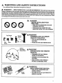
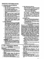
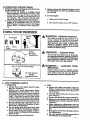
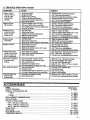
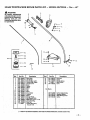
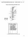
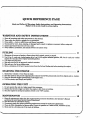
IMPORTANT
MANUAL
Do Not Throw
Away
Operator's
Manual
Model No.
358.799110-21cc
Always
Wear
Eye Protection
8H ,qS/C RRFTSMRN
21cc GAS WEEDWACKER
Ak WARNING:
Read the_Operator's
Manual and
FollowAH
Warnings and Safety
Instructions.
Failure To Do So
Can Result in Serious _ju_.
Fuel Mix40:l
2 Cycle Engine
• Assembly
• Maintenance
• ' Operation
• Repair
Parts
L:
Sold bySears,
530-081079-1.01/26/93
Roebuck
and Co., Hof_an
Estates,
IL
60179
USA
e 1993, Sears, Roebuck
and Co.
:
ONE YEAR
LIMITED
::i/ii/i ¸:
WARRANTY
ON CRAFTSMAN
WE_WACKER@
ii
..............
reeduse.
If this Weedwacker® is usedfor commercialor rentalpurposes,this warrantydoesnot apply.
WARRANTYSERVICEIS AV_LE
BY RETURNING THE UNIT TO THE _ST
SEARSSERVICE CENTERiDEP2_.
IN THE
UNITEDSTATES.This warrantyappliesonly whilethis productis in use in the UnitedStates.
This warranty givesyou specific
legalrights,andyoumayalso
haveot_er
rightswhich
vary
fromstate
tostate.
SEARS, ROEBUCKAND CO. DEP'E D/817WA
HOFFMAN
ESTATES, IL 60179
TABLE
OF CONTENTS
WARNINGS AND SAFETY INSTRUCTIONS
...
KNOW YOUR UNIT .................
. ........
ASSEMBLY ...................................
A. Preparation .............................
B. Hardware Usage ...................
......
C. Assembly Steps ..........................
D. Operating Instructions ....................
ENGINE INFORMATION
....................
A. Fueling Your Engine ... ..................
B. Pre-Operation
Checks: ..................
(3. Starting Instructions. ....................
D. Operating Instructions ...................
USING YOUR TRIMMER .....................
A. Line Trimmer Safety.. ...................
B. Trimmer Line Advance ...................
3
5
6
6
6
6
8
9
9
9
10
11
11
11
12
C. Cutting Methods
................
D. Line Replacement
.......................
GENERAL MAINTENANCE
.................
. .......
12
13
15
A. Maintenance
Safety ......................
B. Air Filter ...............................
C. Drive Shaft Lubrication ..................
D. Carburetor Adjustments
.................
E. StarterRope
.............................
E Trouble Shooting Chart ..................
ACCESSORIES
.............................
INDEX .....................................
_.LUSTRATED
PARTS UST .................
QUICK REFERENCE PAGE .................
15
15
15
16
18
19
19
20
21
27
SPECIFICATIONS
SERIAL
2-Cycte,
DISPLACEMENT:
21cc
:ENGINE RPM:
Operating- -8000
Idle--3400-4000
Solid State
IGNITION:
FUEL
CAP
]
CARBURETOR:
Diaphragm-- All Posi_on With
Adjustable Fuel Mixture Jet
Positive Switch _
ENGINE "OFF":
:Auto Rewind _
STARTER:
,,,,,,
NUMBER
l_---AND STARTING
INSTRUCTIONS
Air Cooled
•
GRIP
SAFETY LABEL
.......11....
......................................
MUFFLER:
Temperature
CUTTING PATH:
16"
FUEL TANI_
............
IAmitin_
IGNITION
_
:'
SWITCH i
SPARKPLUG
_
DRIVE SHAFT
CHOKE
HOUSING
SPARK PLUG:
SPARK PLUG G.AP:
MODULE AIR GAP:
LUBRICATION:
:
.025"
HANDLE-----_
.010" to .014 _ .:
.!;........ __
'""Gasoline/Off _e
- 40il
_\
(see"FuelingYo_ Engine')
CL_TING
LINE:
.080"diameterline
............................................
_¢UFACrwmD tri_lm
4,0_,,91_,,,1,0$2,9_,
4,1sl,s_,01_oRMOREOF
4,1_,812; 4, _3,1_;
_
_
_[
[_[
_]
tS|
_
_
_62,0"/4;
4,4gL98S; 4,2_8_ZS5; 4,823,4_;
US. AND
FOREIGN
PATENTS
PENDING.
4,84_2_,
tt
_
4,1em,e_;
FOL_OW_
4_1:t,004:
US.I,A_
4,,_,6_;
4,940,02.8; 5,020,._z_
SHIELD
....
OI'HER
:
AIRFILTER
,
:? :
THROTTLE
'r_I__x_
:
' ::?_F_,R
_R
:
•
:
,
,
,: , .
,
HEAD'
_
t::.,
........
SPECIAL NOTICE
I_
For users on U.S. Forest Landand in some states,:includmg
C_llfornia(Pt_li¢
Resources Codes 4442 and 4443),
[_
Idaho, Maine, Minnesota, New Jerse_ Oregon, and W_gton:
Certain interna_ combustion engines operated on for- _
est, brush, and/or grass-coy .exedlaud "rathe above areas are required to be equipped with a spark arrestor, maintained in effecfive working orde_ or the engine must be constructed, equipped, and maintained for the prevention of fire. Check with your
[_
state or local authorities for regulations pertaining to these requirements. Failure to follow these requirements is a violation of _
the !aw. This unit is not facto ry.-equipped
with a spark arrestor;, however, a sp_arkarrestor is available as an optional H
part. Ifa spark _estor zsrequ_ed m your area, contact your _
Serwce Center/Department for the correct kit. :.... :
-2-
'
WARNIY GS
(See Additional
A
AYWI)SAFETY
Safety Instructions
WARI_/ING
-
THIS
throughout
POWER
INSTRUCTIONS
this Manual)
TOOL
CANBE
DANGEROUS?
This unit can ¢anse serious
be followed to provide reasonable
safety and efficiency
in using this unit. The operator
is responsible
for
following the warnings
and instructions
in this manual and on the unit. Read the entire Operator's Manual
before assembling and using this unit! Restrict the use of this power tool to persons who read, understand and follow
the wanfings and instructions in this manual and on the unit.
i
i
!,,
_k
ii
DANGER
NEVER USE BLADES WITH
THIS
-
UNIT.
THIS UNIT IS DESIGNED
TRIMMER
-
FOR LINE
USE ONLY
THE BLADE CAN COME OFFAND
SERIOUSLY HURT YOU AND OTHERS.
AW_G
Leg Guards
Thrown
TRIMMER
OBJECTS
, miW!
Face
Shield
Boots
6O Foot
(20 meters)
Hazard Zone
LINE
CAN
THROW
VIO_NTLY.
-
YOU CAN BE BLINDED
INJURED.
OR
-
WEAR EYE AND LEG PROTECTION.
AkW_G
HAZARD
ZONE FOR THROWN
OBJECTS
-
TRIMMER LINE CAN THROW
OBJECTS
VIOLENTLY.
-
OTHERS
INJURED.
-
KEEP PEOPLE AND ANIMALS
30 FEET (10 METERS) AWAY.
CAN BE BLINDED
A WARNING
.r
READ OPERATOR'S
MANUAL.
- FOLLOW ALL WARNINGS
INSTRUCTIONS.
Operater's
Manual
-
FAILURE'TO
AND
DO SO CAN RESULT
SERIOUS_IN_.
IN
" .....
.
i
OR
E.
•
,
,
3
WARNINGS
_k OPERATOR
AND SAFETY
INSTRUCTIONS....(Continued)
SAFETY
1. Always wear eye protection when operating, servicing, or performing maintenance on your unit.
See '_ccessories."
2. Always wear heavy, long pants, boots, and gloves.
Do not go barefoot or wear short pants, sandals,
jewelry, loose clothing, or clothing with loosely
hanging straps, ties, tassels,::: etc; they cau: be
.... caught in moving parts. Secure hair so it is above
sho_der length. Being fully covered will help protect you from pieces of toxic plants such as poison
ivy thrown by the trimmer line, which could be
more of a hazard than touching the plant itself.
3. Do not operate this unit when you are tired, ill, or
under the influence of alcohol, drugs, or medication.
4. Wear hearing protection if you use this unit for
more than 1-1/2 hours per day.
5. Never start or run the en_e
inside a closed room
or building. Breathing exhaust fumes can kill.
6. Keep t_ndles free of,off and fuel.
A
TOOL
SAFETY
1. Inspect entire unit before each use. Replace dam-
2. Replace trimmer head parts that are cr_ked,
chipped, broken, or damagedin any other waybefore using the unit.
3. Use only .080" diameter SEARS Laser Line_.
Never use wire, rope, string etc.
4. Install the shield properly before using the unit.
5. Use only the specked trimmer head. Make sure
the trimmer head is properly installed and securely fastened. Refer to '_kssemb]y."
6. Make carburetor adjustments with the drive shaft
housing supported to prevent the trimmer line
from contacting any object. Hold the unit by hand;
do not use the optional shoulder strap for support.
7. Keep others away when making carburetor adjustments.
8. Use only genuine SEARS accessories as recommended for this unit.
A FUEL
SAFETY
1. Mix and pour fuel outdoors and where there are
no sparks or flames.
2. Use a container approved for fuel
3. De not smoke or allow smoking near fuel or the
unit or while using the unit.
4. Wipe up all fuel spills before starting engine.
5. Move at least 10 feet (3 meters)away
from fueling
site before Starting engine.
6. Stop engine before removing fuel cap.
7. Empty the fuel tank before storing the unit. Use
up fuel left in the carburetor and fuel lines by
stertingthe engine and lettingit run until it stops.
If situ_tions
.....
8. Store unit and fuel in an area where fuel vapors
cannot reach sparks or open flames from water
heaters, electric motors or switches, furnaces, etc.
A CUTTING
SAFETY
1. Inspect the area to be cut before each use. Remove
objects (rocks, broken glass, nails, wire, string,
etc.) which can be thrown or become entangled in
the trimmer head.
2. Keep others including children, animals, bystand ers and helpers outside the 60 foot (20 meter) Hazard Zone. Step the engine immediatebyifyou
are
approached.
3. Always keep the engine on the right-hand
side of
your body.
4. Hold the unit firmly with both hands.
5. Keep firm footing and balance.
Do not overreach.
6. Keep the trhnmer head below waist level.
7. Do not raise the engine above your:waist.
The
trimer head can come dangerously close to your
body.
8. Keep all parts of your body away from trimmer
head and muffler when engine is running.
9. When possible, cut with the left side of the trim_ met head.
10. Use only for jobs explained in this manual.
SAFETY
1.
the unit accordingto
Keep the cutting
recommended proicedures.
line at the proper
length.
2. Disconnect the spark plug before_performing
maintenance except for carburetor adjustments.
3. Make carburetor adjustments with the drive shaft
housing supported to prevent the trimmer Iin_e i
from contacting any object. Hold the unit by
hand; do not use the optional shoulder strap for
support.
4. Keep others away when making carburetor adjustments.
5. Use only genuine SEARS replacement parts as
recommende&
,....
A TRANSPORTING
AND
STORAGE
1. Hand cerry the unit with the engine stopped and
the muffler away from your body.
2. Allow the engine to cool, empty the fuel tau_ and
secure the unit before storing or transporting in a
vehicle.
3. Empty the fuel tank before storing the unit_ Use
up fuel left in the carburetor by starting the engine and lett_g the engine run until it stops.
4. Store unit and fueLin an area Where fuel vapors
cannot reach sparks or open flames from water
heaters, electric motors or switct_es, furnaces, etc.
5. Store umt so line _ter
cannot accidentally
cause injury. The unit can be hung by the drive
sha_housing. '
6. Store the unit out of the reach of children.
occur which are not covered in this manual,
use care and good judgment.
Contact your Authorized
Service Dealer if you need assistance.
IIII I
I....
III
II
ill
I III
I i
I
IIIIIIIIIII
II
l
IIIII
I
IIIIII "
IIIIIIIII
I
II
_i
IIIIII
IIIIIIIIII
III
III
II
I I
IIII
III
I
•
I
I
III_IIIUlil
1/
KNOW YOUR UNIT
IIIII
II
I
IIII I III I1[
A. INTRODUCTION
I
C. CARTON
lU
IIIII
lUmlllI
CONTENTS
¸¸KEY
and sweeping.
Special Features
Include:
•
15" Cutting Path
• Semi-Automatic
Trimmer
•
•
Adjustable
Assist
21cc Engine
B. UNPACKING
Head
Handle
INSTRUCTIONS
1. Afterremoving the contentsfrom the c_ton,
checkpartsagainstthe CartonContentslist.
2. Examine the parts fordamage. Do not use
damaged parts.
3. Notify your SFARS
Service Center!Departme_ immediately
if apart is missing or damagea.
•
NO.
QTY
1.
2.
3.
4.
5.
---
Engine
1
Drive Stmi_ Assembly w/Safety Label 1
Shield
1
Trhnmer Head
1
Assist Handle
1
Operator's Manual (not shown)
1
Loose Parts Bag (not shown)
1
.
7.
8.
9.
10.
B.
C.
NOTE: It is normal to hear the fuel filter rattle in
an empty fuel tenk.
D.
E.
E
LOOSE PARTS BAG CONTENTS:
Bracket - Shield
Wing Nut - Assist Handle
Dust Cup - Drive Shaft Housing
5/32" Hex Wrench
"
Bracket - Assist Handle
Hex Socket Screw - Engine Shroud
ScrewShield
Screw - Throttle Handle
Square Head Screw - Assist Handle
Hex Nut
Washer - Assist Handle
Hardware shown Actual
the "Assembly'section_
1
1
1
1
1
2
2
2
t
3
1
Size in
10°
E.
E
SAFETY NOTICE
Exposu_ to vibrations throughprolonged
use of gasoline powered hand tools could_
bl_d v_l
H dam_. e m the fi_ez, s, _l_a._, and w_" s of people prone to circuIah'on disorder, or abnormal __.
H
er n_e
_
i_
_] occur such _num. oness, pa_._ loss of ..s_. ngth, change m skin color or texture, or loss of feeling in the fingers, [_
nanas or wrm_ msconuuue rne use of this tool and seekmedical attention. Users who operate power tools on a
ntinual and regular basis must monitor closely their physical condition
and the condition
of this tool.
[_
-5-
ASSEMBLY
(If tool is received
assembled,
justed for the operator.)
repeat
all steps
in this section
A. PREPARATION
USAGE
HARDWARE
ACTUAL
assembly
and is ad-
NO
Q__T_:This Hardware is packaged in the Plastic Bag. Refer
to the Hardware reference letters below during assembly.
SHOWN
SIZE
@
@
A.
is correct
1. Read your Operator's
Manual
2. Tools you will need:
- 5/32" Hex Wrench provided with the tool.
- AdjustableWrench
- Standard Screwdriver
This Operator's
Manual is designed to help you assemble the tool and to provide its safe operation. It is
important that you read the entire manual to become
familiar
with thetoolbeforeyou beginassembly.
B. HARDWARE
to be sure
B.
C.
E.
D_
E
Figure I
C. AS SEMBLY
STEPS
l
_
Drive Shaft
NOTE: Hardware referred to in the following sections
are shown in actual size in Figure 1.
f-
1. DRIVE SHAFT HOUSING
(Figure
2 )
a. Remove the packing cover from the straight
end of the drive shaft housing if so equipped.
Make sure the flexible drive shal_ does
not fall out of the drive shaft housing. Dirt on the
Shaft will significantly reduce the life of the tool.
If the flexible drive sh_ falls out of the housing,
,clean'- re-lubricate,,
and re-mstalI."
See the:
Flexible Drive Shaft Lubrication _ section.
?
NOTE: Before performing step b., it might be
necessary to loosen the throttle grip screws/
b. Insert the drive shaft housing through the
throttle grip. Figure 2.
c. Insert drive shaft into the nose cone. Figure 2.
d. Align the bottom groove on the drive shaft
housing with the ridge on the inner, lower wall
of the nose cone opening. Figure 2.
e. Firmly push the drive shaft housing into the
nose cone opening unt_ it bottoms out (about
1-1/2 inches). Make sure the drive shaft; is engaged by pulling the starter rope; if the trimmer head does not turn, reinstall the drive
sha_ housing in the nose cone.
£ Insert the nose cone screws.4- andlock nuts E.;
tighten alternately with the hex wrench until
secure. Figure 2.
g. Slide throttle grip toward engine until it contacts the nose cone. Then, _ert
the throttle
grip screws C. and =tighten until secure.
.?
- 6-
•
....
•
Drive Shaft
Housing
Groove
Nose Cone
k
X
Throttle
"1
Flexible
Drive Shaft
!
Screws C.
Lock-Nut
E.
DriveShal%
Shaft
2. AS SIST HAI'w-D_
between
housing.
engine
and safety
label
on drive
Assist Handle
• Screw D.
Assist Handle
a. Insert the end of the drive shaft housing through
the assist handle. Figure 3 (inset).
b. Align the assist handle between the safety !_el
: and the throttle trigger housing. Seat drive shaft
housing in the groove in the assist handle. Figure3.
Insert the tab on the assist handle bracket into the
slot oil the assist handle. Figure 3. Then, lay the
assist handle bracket into place over the drive
shaft housing.
d. Insert the screw down through the hole in the assist handle bracket and then through the assist
handle. Figare 3.
e. Assemble the washer andwingnut onto the screw.
Tighten securely.
Washer E
shaft
Groove
Figure 3.
Z .Adjust
assist
handle up or down the sha_ housing
for comfort. Figure 3.
3.
, ,
HEAD
TRIMMER
,m
,,,,,,,
,
a. Place the Dust Cup on the Drive Shaft Housing
over the hex nut that is assembled on the arbor
Shaft. Figure 4.
b. Hold the Dust Cup with a wrench to keep the
Arbor Shaft from turning.
c. Thread the Trimmer Head onto the Arbor
Shaft against the Dust Cup and hand tighten
firmly. Figure4.
NOTE: Unless Trimmer Head is tightened adequately, it can unthread when engine is started
or stopped. If this situation occurs, reinstall
the Trimmer Head and tighten more securely.
Direction
to Install
Nut
Cup
Figure 4
d. Press the Tap Button and pull a minimum of 4
inches of Line from the Trimmer Head. Figure 5. Approximately 2 inches of line can be
advanced each time the Tap Button is pressed.
Button is pressed.
Tap Button
To remove Trimmer Head, hold Dust Cup
with a wrench and unthread Trimmer Head.
4. SHIELD
I
Figure 5
, i ,,,
ATTACHMENT
A WARNING
Arbor Shaft
I
IThe shield must be properly installed. Thel
,,,,,, ,
Widest Part
ofShield-_
Toward
_
Engine
Bracket
Screws
I shield provides partial protection
from the riskI
Iof thrown objects to the operator and others and
!is equipped with a line limiter which cuts excess I
!1.Lneto the proper length.
!
I
a WARNmQ
..........
I
Do not alter or remove
the Bracket Tab. Whenl
installed
correctly;
the Bracket
Tab ensures l
proper shield _llgnment.
Failure to ins.tall the l
shield
in
the
position
shown
m
Fig-I
ures 6 and 7 can result in serious injury to the I
opera, or.
The line limiter (on the underside
the shield) is sharp and can cut you.
of
a. Match theTab ontheBracketwiththehole on
the Drive Shaft Housing.
Figure6
b. Attach the Shield to the Bracket with the two
screws as shown in Figure 6.
_TE;
!t is easier to start Screws with a screwdxivel- and _sh
tightening with a wrench.
c. Tighten the Screws evenly and securely.
It is possible that a small space will be left
en the Bracket and the Shield when the
screws are fully tightened.
Figure6 (inset).
-7-
5. OPERATING
:
POSITION
OPERATING
POSITION
a. Before
starting the engine, stand as shown in
_Figure 7 and check for the following:
I. Lef_ arm fully extended, hand holding Assist
Handle. _
2. Right arm slightlybent, hand holding Throttle
Grip, fingers on Throttle Trigger.
3. Engine below waist level.
4. Weight of tool evenly distributed between
Eye Protection
extended, hand
holding Assist
Trimmer Head
near to gruund
and easily contacts material
to be cut
arms.
5. Without operator bending over, the Trimmer
Head isnear
and parallel torthe ground and
easily contactsthe material to be cot ..........
b. Adjust the Assist _dle
up or down.the Drive
Shaft Housing(but
above thesafety
labels) to a
comfortable position.
1. Loosen Wing Nut by hand and adjust Assist
Handle. Retighten Wing Nut by hand o_/y.
2. Rotate Assist Handle from lef_ to right to tilt
the augle of the Trimmer Head when _atting a
large, sloped area such as a ditch bank.
i
iiiml,
iiIHI
ii
waist level
i
NOTES
-8-
Haud holding
Throttle Grip,
Fingers on
Throttle Trigger
/
Figure 7
ENGINE INFORMATION
A. FUELING
YOUR
ENGINE
1.FUEL SAFETY
3. USE THE FOLLOWING:
SEARS CRAFTSMAN 2-cycle engine oil _ed
at 40:1 is strongly recommended_ Consult the
instructions on oil container for proper mixing.
1 PART OIL TO 40 PARTS GASOLINE=
3.2 ft. oz. oil to i gallon gasoline
8.0 ft. oz. oil to 2.5 gallon gasoline
Not all air cooled 2-cycle engine oils have the
same qualities.
If SEARS CRAFI'SMAN
2-_cle
engine_ oil is not available, use a good
quality, 2-cycle
engine oil recommended
for
air-cooled engines. Mix at a ratio of 16:1 (8 oz.
oil to I gallon gasoline). A 16:1 fuet mixture with
these oils will assure adequate lubrication for
.....your engine.
a. Use only recommended
fuel mixtures.
b. Mix and pour fuel outdoors
and where
there are no sparks or flames.
c. Use a container
approved for fuel.
d. Do not smoke or allow smoking near fuel
•or the unit or while using the unit.
e. Wipe up all fuel spills before starting the
engine.
£ Move at least 10 feet (3 meters)
away
from fueling
site before starting engine.
g. Stop engine before
removing
fuel cap.
Allow engine to cool before refueling.
h. Before storing the unit, use up fuel left in
..... the fuel lines and carburetor by starting the
engine and letting it _.Jn until it stops.
i. Store unit and fuel m an area where fuel
vapors
cannot
reach
sparks
or open
flames from water heaters, electric motors or
switches, furnaces, etc.
4. DO NOT USE:
•
2. FUEL MIXTURE
Marine Manufac(formerly BIA oil)--
.....
A CAUTION
Experience
indicates
that alcohol blended fuels
(tailed
gasohol
or using ethanol
or methanol)
can attract moisturewhich
leads to separation
and formation
of acids during storage.
Acidic
gas can damage
the fuel system of an engine
while in storage.
To avoid engine problems,
do
not leave fuel in the unit when storing for 30
days or longer.
Start the engineand
let it run
until the fuel lines and carburetor
are empty.
Use fresh fuel next season.
See the "Storage"
section
for additional
information.
Never use
engine or carburetor
cleaner
products
in the
fuel tank or permanent
damage can occur.
5. HOW TO MIX FIlL
r
_k"
_l
t_
:in
:::
:
Oil--National
Association
• AUTOMOTIVE
OIL-Does not have proper additives for air-cooled0
2-cycle engines and can cause engine damage.
e. Your unit is powered
by a 2-cycle
engine
which requires a fuel mixture
of regular
unleaded
gas?!ine and a high quality engine oil spemally made for 2-cycle,
air
cooled engines.
The internal design of the
2-cycle engine requires lubrication of moving
parts. Lubrication is provided when the recommended mixture of gasoline and oil is used.
b. Genuine Sears 40:1, 2-cycle
engine oil is
strongly
recommended
for the protection
of your unit. Extensive englneeringtests
have
proven that Sears 2-cycle
engine oil resists
break-down
at operating temperatures common to 2-cycle engines, resulting in dependable performance and longer engine life.
c. Gasoline must be clean and not over two
months
old. After a short period of time,
gasoline wilt chemically break down and form
compounds thatcausehard starting and dami age m 2-cycle engines.
d. The correct measure
of gasoline to oil is
very important.
Too much oil in the mixture
will foul the spark plug.
_
Too little oil or incorrect
oil
_iwill cause engine to overheat
and seize.
e_i:_
Always mi_ the fuel thoroughly
in a con: ii tainer since gasoline and oil do not readily
::: combine. Do not mix gasoline and oil directly
B. PRE-OPERATION
NMM
turers
CHECKS
..........................................
.....
I
A WARNING
_
, [
]Review all Warnings and Safety Instructions
ml
I thismanual.
!
1. Before operating
y.our unit, always:
Inspect
the entire unit before each use. Replace damaged parts. Check for fuel leaks and
make sure all fasteners are in place and securely
fastened.
.....
b. Replace
trimmer
head
parts
that
are
cracked,
chipped,
broken,
or damaged
in
any other way before using the unit.
c. Use only .080" diameter
Sears
Laser Line.
Never use wire, rope, string, etc_
d. Use only with the shield properly attached.
AND FILL TANK
a.: Pour the proper measure of engine oil into an
approved, marked container.
Then, flU the
container with regular unleaded gasoline.
NOTE: If fuel is alreadyin the container, add the
::, :: proper measure of engine oil. Then, close the
container tightly and shake it momentarily.
NOTE: Do not mix gasoline and oil directly in the
:: fuel tank.
b. Using a spout or funnel, fill the fuel tank with
.... fuel mix.
c. 1_
the fuel caps securely.
e. Use only the specified
trimmer
head. See
"Specifications." Make sure the trimmer head is
•
properly installed and securely fastened. Refer to
_Assembly. _
-_
f. Make
carburetor
adjustments
with
the
drive shaft housing
supported
to prevent
trimmer line from contacting
any object. Hold
unit by hand; do not use optional shoulder strap
for support.
g,
Keep others away when making carburetor
adjustments.
h. Use only genuine Sears accessories
or attachments recommended
for this unit.
i. Clean
air filter if dirty before operating
unit. Refer to "Specifications, _ for air filter location.
C. STARTING
(For location
I. Before
INSTRUCTIONS
of controls, refer to "Speeifica_ons.')
startingthe Engine:
a. Fuel engine. Move 10feet (3 meters) away from
fue_ng site.
b. Extend lines approximately 4 inches from Trimmer Head to provide adequate load on engine.
3. For a Warm Engine:
a. Move ignition switch (Figure 9 ) to the on position.
b. Move Choke to "Half Choke"• position. Figure 9.
c. Grasp Throttle Grip and squeeze Throttle Trig-
Figure 8.
c. Rest Engine and Shield on ground, supporting
Trimmer
Head off ground
away from trees,
bushes, Onlookers, etc. Figure 8
d, Start engine before lifting tool to operating posi.
tion.
2. Fora Cold Engine
ning out of Fuel:
or a Warm Engine
get
d. Pull Starter Rope sharply until engine runs, but
no more than 5 pulls. Keep Trigger fully squeezed
until engine runs smoothly.
after run.
a. Move iignition switch (Figure 9 ) to the on position.
b. MoveChoke
to "Full Choke" position. Figure 9.
c. Grasp Throttle Grip and squeeze Throttle Trigger fi_y. Keep Throttle Trigger fully squeezed unEl engine runs smoothly (through step "g. ")
d. Pull Starter Rope sharply until engine attempts
to run, but no more than 8 pulls at full choke to
avoid flooding the engine.
The "attempt to
run" may be hard to hear. The operator must
Ustencarefully.
After 8 pulls, proceed to step
"e." even if the engine has not attempted to run.
e. Move Choke to "Half Choke_ position. Figure 9.
f. Pull the Starter Rope sharply until _the engine
runs, bUt no more than 5 pulls.
NOTE: If the engine has not started
steps "a." through "f."
Ife,e
does not run after 5 pu!Is, it is probably
flooded. Wait a few minutes and repeat procedure with
Choke at "Off Choke" position. Figure 9.
e. Move Choke to "Off Choke" position.
I STARTING POSITION I
after 5 pulls, repeat
Ngm'e 8
g. Allowengine
to run 5 seconds, then push Choke to
"Off Choke" position. Figure 9. Keep Throttle
Trigger squeezed until engine runs smoothly.
.........
I_'_on
Switch
Choke
Lever
If engine dies with Choke at "Off Choke" position, repeat steps "e." through "g."
If engine does not start, pull Starter Rope 5
more pulls. If engine still does not run, it is probably
flooded. Wait a few minutes and repeat procedure with
Choke at "Off Choke" position. Figure 9.
Figure 9
ii
ii ii
NOTES
- 10-
Figure 9.
ii1[
i
Do OPERATING
INSTRUCTIONS
1. Bring the engine to cutting speed before entering the material
to be cut.
Do not run the engine
ata
higher
speed
than necessary.
The cutting line will cut effidently when the engine is run at less than full
throttle.At lower speeds, there is less engine noise
and vibration.
The .cut__ line wil! last longer
and will be less likely to 'weld" onto the spool.
b. If the Trimmer
Head does not turn when the
engine is in operation,
make sure the Drive
Sha_ Housing is properly seated in the Engine
Shroud. Refer to '_ssembly, Drive Sha_ Housing."
iiiiiI
USING
i,
'
i l_liII ill
2. Always release
low the engine
not cutting.
the Throttle
Trigger and alto return
to idle speed when
3. To stop engine:
a_ Release
the Throttle
Trigger.
b. Move Ignition Switch to the "Off" position.
i
YOUR TRIMMER
A
Thrown
WARNING-
THROWS OBJECTS
The rapidly moving line causes objects to be
thrown violently. The shield will not provide
complete protection to the operator or others.
•
,
Leg Guards
Face
Shield
Objeit
Boots
_
60 Foot
meter)
Hazard Zone
Tap-N-Go
A
WARNING
- HAZARD ZONE
This tool will throw objects and cut. Keep others i_cluding
chiTdren, animals, bystanders and helpers at least 30 feet( 10 meters)
away from the operator
and tool. Stop
the engine ffyou are approached.
WARNING
® HI Trimmer Head
-
DAMAGED TRIM-
MER HEAD
Trlmmer head parts __at are chipped, cracked
or damaged in any other way can fly apart and
cause serious inj_ury. Do not use. Replace
damaged parts before using the tool
Use Only Genuine
SEARS
Replacement Parts
] i]]]
A. LINE
TRIMMER
shield
......
or gog-
b. Always
wear heavy, long pants,
boots,
and gloves. See _.ccessories.
Do not wear
loose clothing, jewelry, short pants, sandals or
go barefoot. Secure hair so it is above shoulder
leng_.
Being fully covered will help protect
you from pieces of toxic plants such as poison
ivy thrown by the trimmer head which could be
more of a hazard than touching the plant itself.
c- Do not operate
this tool when you are
tired, ill or under the influence
of alcohol, drugs or medication.
:
d. Do not swing tool with such force that
you are in danger of losing your bal_ee.
e. Never start or run the engine
i_ide
a
• closed room or building. Breathing exhaust
fumes cen kffi,
Keep h_dles
tll
SAFETY
1. OPERATOR
Always:wear
a face safety
gles. See %.ccessories."
f.
i
.....
free of oil and fuel.
2. TOOL
a. Inspect
the entire tool before each use.
Replace damaged parts. Check for fue! leaks
and make sure all fasteners are in place and securely fastene&
b. Use only .080" diameter
rope, string, etc.
Line:Never use wire,
c. Be sure the-:_hield is properly attached.
d. Make sure the trimmer
head is properly
installed
and securely
fastened.
Refer to
'_ssembly."
e. Make carburetor
adjustments
with the
thd_eveshaft h onsing supported
to prevent
trimmer line from contacting
any object.
f. Keep others away when making carburetor adjustments.
g. Use only genuine
SEARS accessories
or
attachments
as recommended.
- 11 -
-
3. CUTTING
f. When possible,
cut with the left side of
the trimmer head.
g. Do not raise the engine above your waist.
h. Keep all parts of your body away from the
trimmer line when the engine m running.
i. Keep all parts of your body away from a
hot muffler.
°
j° Use only fo r 3obs
explained
in this manuaL
_. Inspect
the area to be cut before
each
use. Remove objects (rocks, broken glass,
nails, wire, string, etc.) which can be thrown or
become entangled in the trimmer head.
b. Always keep the
hand side of your
engine
body.
c. Hold the tool firmly
d. Keep firm
over-reach.
[I
B. TRIMMER
•
and balance.
Do not
head below waist
level.
II
LINE
right-
with both hands.
footing
e. Keep the trimmer
on the
III
Avoid any contact
with a hot muffler.
....... can causeA serious
WARN_G
muffler
burns.
I
ADVANCE
I
IIIIJ[
C. CUTTING
The trimmer
line will advance
approximately 2 inches each time the bottom oft.he
trimmer head is tapped on the ground with
theengine
running at full throttle.
•
The most efficient
llne length is the maximum length allowed by the line limiter.
•
Always keep the shield in place when
tool zs being operated.
Figure
10.
•
To Advance
Line:
•
3. Tap the bottom of the trimmer head lightly on
the ground one time. See Figure 10. Approximately 2 inches of line will be advancedwith
each tap.
NOTE__:Always tap the trimmer head on a grassy
area. Tapping on surfaces such as concrete or
asphalt can cause excessive wear to the trimmer head.
•
The line will easily remove grass and weeds
from around
walls, fences, trees and flower
beds, but it also can cut the tender bark of
trees or shrubs and scar fences. To help avoid
damage especia_y to delicate vegetation or trees
with tender bark, shorten line to 4-5 inches and
use at less than _
throttle.
Formowingorsweeping,
a good clean job.
use full throttle
_ Line Crowded Into
Does The C_
| Work Area
To Advance Line,
Tap B0ttom Of
Trimmer Head
On Ground One
Time.
Ground
i
- 12 -
METHODS
Tip of the Line
To Proper Length.
Figure i0
LI
• For trimming
or scalping,
use less than full
throttle
to increase
line life and decrease
head wear, especially:
- during light duty cutting.
- near objects around which the line can wrap
such as small posts, trees or fence wire.
NOTE:
If the line is worn down to two
inches or less, more than one tap win be required to obtain the most efficient line length.
Cuts Line
II
The tip of the line does the cutting. You will
achieve the best performance and minimum line
wear by not crowding the Hne into the cutting
area. The right and wrong ways axe shown in Figure 11.
1. Operate the engine at fu!l throttle.
2. Hold the trimmer head pamllet to and above
Line _ter
III
]
A WARNING
[
Use _um
speed and do not crowd the line[
when cutting around hard objects (rock, gravel, J
fenceposts,
etc), which can damage the trimmerl
head, become
entangled
in the line, or be[
thrown causing a serious hazard.
J
the
A WARNING
................
Useoonly,080"
diameter
line. Other sizes of
line
wiI1 not advance properly
and can cause serious
injury. Do not use other materials
such as wire,
string, rope, etc. Wire can break off during cutring and become
a dangerous
missile that can
cause serious injury.
I
A hot
RIGOr
'1
WRONG
Figure 11
AwAR . q
for
.............
I
Always wear eye protection.
Never lean over the I
trimmer head.
Rocks or debris can ricochet
or[
be thrown into eyes _
face and cause blind-[
heSS or other serious iz_ury.
J
1. TRIMMING - Figure
12. Hold the bottom of
the trimmer head about 3 inches above the ground _
and at an angle. Allow only the tip of the line to
make contact. Do not force the trimmer line into
the work area.
•:TRIMMING
3 Inches"
Above Ground
Figure 12
SCALPING - FIGURE
13. The scalping technique removes unwanted vegetation. Hold the
bottom of the trimmer head about 3 inches above
the ground and at an angle. Allow the tip of the
line to strike the ground around trees, posts,
monuments,
etc. This technique increases line
2_
wear,
Figure 13
.
MOWINGfor mowing
Figure
14. Your trimmer is ideal
in places conventional lawn mowers
MOWING
cannot reach. In the mowing position, keep the
line parallel to the ground. Avoid pressing the
head into the ground as this can scalp the ground
and damage the too!.
Figure
14
J
1
SWEEPING - Figure
15. The fanning action
of the rotatingline
can be used for a quick and easy
clean up. Keep the line parallel to and above the
surfaces being swept and move the too! from side
to side.
SWEEPING
Figure
15
illll illu
D.
LINE
•
REPLACEMENT
For properline
.
feed:
Use only genuine
SEARS
pre-wound
spools and .080" diameter
line. The use of
other types of spools or Lines can result in excessive breakage, line welding, and improper
line feed.
- Pre-wound
spools offer the most convertlent method for replacing
line as well as
optimum performance.
.......
•
w/lAne
a. Hold the Trimmer Head as shown:in
(
Figure 16
Always clean dirt and debris from the spool
and hub when performing any type maintenance.
1. Installing
:
i
Spool
Fig-
u.re 16. Press the two Lock Tabs and remove
the cover. Figure 16.
....
b. Remove the Spool. Figure
17
c. Clean dirt and debris from al! parts.
d. Inspect all Trimmer head parts for damage.
Replace damaged parts.
I
A WARNING
Figure
i_
Trimmer head parts that are chipped,
cracked]
or damaged
in any way can fly ap_
and cause I
seraotls _ur_
Do _not use. Repliice
damaged[
parrs he,ore using the tool.
:
i
17
e. Catch the line in the notch in the spool. Figure 18 (inset).
Leave about 4 inches of line
hanging from the spoo!.
f. Place your index finger overthe line and notch
as shown m Figure18. Insertthe end ofthe
Line in the Line Exit Hole. Figure 18.
- 13 -
g. Align the line andnotch
I
with the Line Exit
Hole. Figure 18. Place Spoo! in Hub. Make
sure the Trimmer Line is not caught between:
the rim of the Spool and the Hub.
To seat t._e spool in the Hub, it may be
necessary to pull the line through the Line Exit
Hole until the spool drops into place.
•
h. Align the Lock Tabs on the Cover over the
Catches on the Hub. Push the Cover down
onto the Hub until the parts snap together.
Finger Over Notch
/
Line Exit Hole
Figure !9.
Figure
18
Catch
i.
Check to make sure the Lock Tabs are properly
fastened as shown in Figure 19 (inset).
j.
Obtain correct line length (4 inches) bypressing the Tap Button (Figure 20 ) and pulling on
the line again.
Tab Seated
In Catch
N_TE:
tf tap button gets knocked out of the hub,
reassemble parts as follows:
Figure 19
1. Remove the cover and spool.
2. Place the spring in the hub cylinder.
Figure 21 (inset).
3. Placethetap buttonover thespringand hub
cylinder.
4. Aligntheslots
inthetapbuttonwiththefinsin
the base of the hub. Figure21 (inset).
Push
partstogether.
Tap Button
5. Reinstal!
thespooland cover.
2. Installing
Line
Figure 20
on Spool
To replace
the Line on existing Spool:
!.) Follow "Installing
Spool w/Line," steps
"a.-d." and remove any _e remaining on
the Spool.
2.)Use a 25 footlengthof.080"diameterline.
3.) Insert about 1/4 inch of the end of the line
through the hole in the inner rim of the
Spool.Figure21. Allow no more than i/2
•inch of lineto extend beyond the rim to
avoidinterference
with tappingaction.
.....
4.)Wrap the lineonto the spoolas shown by
the arrow. Figure 21.
The Line must be wrappod
evenly for proper line feed. _::
"_
Wrap As
Shown By
Spool
Inner
Rim
3. Trouble
•
b. If the Line breaks
off or backs up in the
Trimmer Head_ follow ,In_ling
Spool w/
i: Line,? steps "a:-&"
slack in Line until
the Line is tightly wound on Spool,leavin.g
4-6 inchesof extended_e.
Continuewith
steps %.-j._
firmly and
-,Too
- 14 -
j"
Shooting
the THmmer
Does not advance
or breaks
ring:.
- Improperly wound onto/spool!
- Line size incorrect.
little line outside head.
while
Head
1/4 _ of
Line:
Figure21
51)Follow "InstallingSpool wfLine" steps
"e
(
and Line
•
cut.....
Pulls back into hea&
- Too little lineoutside of head.
• Welds onto spool:
:
- Line sizeincorrect.
-: Crowding tine against material being cut,
:-Cutting
at higher speeds thannecessary.
:
, Improparly wound onto spool.
......
:
GENERAL
MAINTENANCE
A_ MAINTENANCE
SAFETY
1. Maintain
the tool
mended procedures.
the proper length.
2. Disconnect
the
ing maintenance
meats.
3. Make
according
to recomKeep the cutting line at
spark plug before performexcept for carburetor adjust*
carburetor
adjustments
with
the
jeer.
.
Keep others
adjustments.
away when making
|
,
carburetor
5. Replace
trimmer
head
parts
that
cracked,
chipped2, broken,
or damaged
any omer way before using the tool.
6. Use o_ly SEARS
.080" diameter
use wire,rope, string, etc.
7. Use only genuine
SEARS
parts as recommended.
line.
are
in
Never
replacement
8. Inspect
the entire
tooL Replace damaged
parts. Check for fuel leaks and make sure all fasteners are in place and securely fastened.
,,
B. AIR FILTER
sumption.
Air
Filter
Do not clean the air filter in gaso.
line or other flammable
solvent
to avoid
creating
a fire hazard.
1. Clean
the Air Filter:
•
Always after 5 tanks of fuel or 5 hours of
operation,
which ever is less.
•
More frequentl3_ in dusty conditions.
a. Remove the two screws from the air filter
cover. Remove air filter cover. Figure 22.
b. Remove the air filter. Figure 22.
Air Filter Cover
Figure 22
If replacing
ter _52-701614.
c. Wash f_ter in soap and water.
d. Squeeze filter dry and reinstall.
e. Reinstall the air filter cover. Install the
screws and tighten securel_
i
C. DRIVE
•
SHAFT
Lubricate
the Drive Shaft:
- After each ten (10) hours of operation.
- Before
operating
if the tool has been
stored for 90 days or longer.
Use the
sults:
•
following
Use Flex shaft
procedure
Lube PartNo.
Make sure the air filter is fitted
into the corners of the cover to keep dust
from entering
the engine and causing engine damage.
IIIII IIIII
LUBRICATION
for
best
re-
530-030139.
Lay drive shaft
on a clean surface. Avoid laying the shaft on the floor,
ground or on any other surface
that may
nave dirt or debris. Even after wiping
the
shaft, grease residue can pick up dirt particles that can cause dam_e
or prematttre
failure:
I CAUTION; 1 Take care to avoid i_ury
your
hands and fingers with broken wires when
checking
for damage or wiping
the drive
•
shaft:=A, eloth will not prevent broken wires
from puncturing
or tearing your skin.
1. Loosen the screws in the throttle grip.
2. Loosen the screws in the nose cone. Slide the
• drive sha_ hou_
out of the nose cone, then
out of the throttle grip.
the air Falter, use air fil-
Ii
I
II
3. Remove the drive shaft from the drive shaft
housing. Figure 23.
4. Check the drive shai_ for broken wires, twists
or kinks, and replace if damage is found.
5. Using a clean cloth, wipe the drive shaft thoroug_y to remove any old grease, Figure 23.
6. Apply a uniform coat of lube to the entire surface of the drive shaft.
7. Inject the remaining contents of the tube into
the top of the drive shaft housing,
8. Replace drive shaft in the drive shaft housing.
l_gure 23.
9. Reas. semble drive shaft housingto the throttle
grip _nd the nose cone. Tighten nose cone
screws and throttle grip screws securely.
Drive
\
Drive Shaft
Housing
Figure 23
- 15-
D. CARBURETOR
ADJUST1KENTS
This is a complicated
task. Read all warnings and instructions
justments.
If you do not think that you completely
understand
all _
SEARS Service Center/Department
perform these adjustments.
2. BASIC
thoroughly
before starting adand instructions,
let your
CARBURETOR
SETTINGS
NOTE: In most cases, your engine can be made to
run properly with minor carburetor adjustments.
Refer to "Trouble Shooting Suggestions" in the
lef_ column for the condition you are experiencing
and follow the instructions. The basic carburetor
se_
are provided below ....
=
A
Keep others
ustments.
away
'................
i
when
making
carburetor
ad-
!
III
Serious i_ury toAthe
operator
WARr
G and others can occur if the carburetor
is not properly adjusted.
]
.....
a Turn the mixture screw (Hgure 24 ) c]oc.=._vJse
until it stops. Do notturn t_ screw untilitis
tight as damage to theneedle seatcan occur.
b. Turn the mixture screw between three-quarters and one fiflt turn counterclockwise.
3. ADJUSTING
PROCEDURE
a. PREPARATION
1. Use a fresh fuel mi_
. •
•
The carburetor
at the factory.
has been carefully
adjusted
However, the operator
must
tions'.
•
•
Very small adjustments
can affect
engine
performance.
It is important to turn the screw a
very small amount per adjustment
and test performance before making further adjustments.
Each adjustment
should be no more than the
width of the slot in the adjusting screw.
This is a complicated
task and it is important to follow
instructions
in sequence
as
indicated.
1. TROUBLE SHOOTING
SUGGESTIONS
- Engine will not continue to run at idle position. See "Idle Speed Adjustment" and "Low
Speed Mixture Adjustment."
- Engine dies or hesitates when it should accelerate. See '_cceleration
Check."
Loss of cutting power wblch camuot be cor:rected by cleaning the air filter. See "High
Speed Mixture Adjustment."
- Engine does not return to idle from full throt_
tle within
2 seconds. See "Deceleration
Check."
gme?
See "FuelingYour
En-
_
2. Make sure the line extends to the length a!lowed by the line limiter to provide correct
load on engine.
3.: Start the engine. Cut grass for 3 minutes to
warm en_ne. The engine must be at operating temperature before carburetor adjust- mentscan beperformed correctly.
b. IDLE SPEED
ADJUSTMENT
1. Allow engine to idle.
2. Adjust idle speed screw (Figure 24 ) unti!
the engine continues to run without stallrag.
- Turn screw clockwise to increase engine
speed if the engine stalls or dies.
- Turn screw counterclockwise
to slow en-
down.
3.
Follow
instructions
in
'_cceleration
Check" and "Deceleration Check."
4. No further adjustments
are necessary if
performance is satisfactory.
-
-
IT
he
Engine w_ not rur_.See =Trouble Shooting
Chart." Then, if the carburetor requires adjustment,
begin with "Basic Carburetor Settings."
trimmer line will be spinning
]procedure.
Wear your protective
[observe all safety instructions.
- 16-
during this
equipment
and
e. ACCELERATION
CHECK
1. Allow engine to idle.
2. Squeeze trigger fully
a If performance
is satisfactor_
ceed to "d. Deceleration Check."
pro-
b. If the eng_e
does not accelerate
smoothl_ turn the MixtureScrew (FiglLre 24 ) counterclo_e
a small
amount (no more than the width of the
slot in the adjusting screw).
3. Repeat step "2." until smooth acceleration
is obtained.
It may be necessary to repeat _Idle Speed
Adjustment" through '_cceleration
Check," to
obtain correct adjustments.
4, Follow
Lustructions
in "Deceleration
Checl_"
& DECE_RATION
CHECK
1. Allow engine to idle, then squeeze throttle
trigger fully.
2. Allow engine to run at fun speed for about 1
second.
e. MIXTURE
ADJUSTMENT
I CA_TIoN:
IDo not operate
engine
at full
throttle
for prolonged
periods while making mixture
adjustments
as damage to the
3. Release the throttle trigger to the idle position _d listen to the deceleration of the engine. It must ret_Jxn to idle sm0ot_y and
within i to 2 seconds.
1. Support the drive sha_ housingso the trimmet head is off the ground and the line will
not make contact with any object.
a. If performance
is satisfactory;
no
further adjustments are necessary.
b. If the engine slowly or erratically
returns to iaeor
idles erratically,
proceed to "MixbJxe Adjustment."
NOTE: Perform steps "3." through "5." at full
throttle.
2. Start the engine. Allow engine to idle, then
squeeze throttle trigger fi_lly.
3. Turn mixture
screw (Figure24)
very
slowly clock-wise until engine speed is reduced.
4. Turn mixture screw very s!owly counterclockwise. Stop when the engine begins to
run roughly.
5. Turn the screw
amount clockwise
smoothly.
slowly the _um
until the engine runs
6. Follow instructions in "Acceleration
Check" and "Deceleration
Check".
Idle
Speed
,
,_--:Air
Adjustment
Filter: : Screw
Figure 24
:
ii iiii ii
[CAIYPION: [Ifthe engine does not operate according to these instructionsafterrepeati_g the adjusting steps,do not use the tool.
Take itto your nearest Sears Service Center/Department.
i
NOTES
ii¸•,
- I7 -
E. STARTER
ROPE
• Replacea StarterRope that breaks.
21. Hold the rope taut at the rope exit hole so the
pulley will not move. Remove hex wrench.
22. Reverse steps 1. through 8. to re-assemble.
A WARNinG
1. Disconnect spark plug wire. Figure 25.
2. Loosen the nose cone screws. Figure 25.
"Nose Cone _ Screws
3. Separate
the drive shaft housing/throttle
grip
from the engine.
4. Disconnect the throttle cable (Z fitting) from the
throttle lever as follows:
a
5.
6.
7.
8.
9.
10.
11.
12.
13.
14.
15.
pivot the throt_e
cable;
lever toward
the throttle
Drive Shaft
Throttle
Figure 2,5
_!_i
b. turn the Z fitting sideways (Figure 26 );
c. remove
the Z fitting from the hole in the
throttle lever, then rpJease the throttle lever.
S_eeze
the snap fitting and remove it from the
p_ey housing. Figure 26.
Remove the five pulley housing screws (four on
the front, one by the spark plug) with the small
hex wrench provided. Figure 25 (inset).
Separate the pulley housing from the engine.
Disconnect switch wires from switchl Figure 27.
Remove the rope retention screw. Figure 28: Remove any remaining rope from around the pulley
ratchet. Figure 28.
Hold pulley housing as shown in Figure 28 .Hand
turn the pulley clockwise as far as it will go.
.......
Turn the pulley counterc!o_e
until the pulley
notch is aligned with the housingnotch
next to the
retaining tab and screw. Figure 28.
Then, turn the pulley one complete turn counterclo_e
unt_ the notches are aligned again.
Insert the hex wrench into the hole formed by the
notches to hold the pulley in position. Figure 28 (inset-upper
left).
Use a 42" length of replacement rope.
Move away 10 feet (3 meters) from the fuel tank
with the replacement rope. Use a match and melt
both ends of the rope to prevent fraying.
_:'_
Figure 27
Figure 26
Rope
Taft
16. Pull melted ends through a thick, clean ragwhile
theropeisstill
hottoobtainsmooth,pointedends.
17. Insertone end oftheropethroughthehandleand
securewith a knot. Leave a 3/16"pigt_,behind
theknot. Figure28 (inset-upperright).
18. Inserttheotherend oftheropethroughtherope
•
exitholeintothe insideof the housing,intothe
pulleyand up through thepulleyhole.Figure28.
19.Wrap the rope counterclockwisearound the
pulleyratchetand tucklooseend under the rope
atthepulleyhole.Figure28. Leave a I inchtail
tayingflat on top of the pulley 5etzoeen the retainer
rib and the retention post as shown in Figure 28.
The rope taft must net extend beyond the raised
circle on the pulley to prevent interference with
the retaining tab. Figure 28.
20. Thread the rope retainer screw into the retainer
post. Figure 28. Do not overtighten screw.
- 18-
||
|!
Puney
Notch
Housing
Notch
Figure 28
E TROUB_
SHOOTING
CHART
_JL
CAUSE
REMEDY
i.
ii
Engine will not" .....
1.'Fuel tank empty.
......
1. Fill tank with correct fuel mixture
start or will run
.... 2. Engine flooded .....
- ' 2. See "Starting Instructions."
only for a few
3. Spark plug not firing.
:;
3. Install new plug/check ignition system.
seconds after
4. Fuel not reaching carburetor.
4. Clean fuel filter; inspect fuel line.
starting. •
5. Carburetor requires adjustment.
5. See "Carburetor Adjustments."
6. None of the above.
......
6. Contact your Service De_]er_
En_e
will not
1. Seethe "Throttle Cable" section.
idle properly.
2. Idle speed Set too fast or too slow.
2. See "Carburetor Adjustments."
3. Low speed mixture redes
adjustment _. 3. See "Carburetor Adjustments."
: :
4-N °ne of the above.
...............
4. Contact ,your Authorized Service Dealer.
1. Air filter dirty.
i. Clean or replace air filter.
•
accelerate, lacks
2. Spark plugfouled.
2. Clean or replace spark plug and re-gap.
power, or dies
3. Carburetor requires adjustment.
3. See "Carburetor Adjustments."
under a load.
4. Muffler outlets plugged.
4. Contact your Authorized Service Dealer.
5. None of the above.
,
5. Contact your Authorized Service De_ler.
1. Air filter dirty.
1. Clean or replace air filter.
excessively.
2. Fuel mixtm'eincorrect.
:- 2. Refuel with correct fuel _e.
' 3,
Highspeed mixturerequires,,
adjustment.
3. See Carburetor Adjustments.
.........
Engine runs hot.
1. Fuel mi_._re "incorrect.
1. See "Fueling'Your Umt."
2. Spark plug incorrect.
2. Replace with correct plug ....
3. High speed mixture set too low (Lean).
3. See "Carburetor Adjustments."
4. None of the above.
Cutting Head stops
under a load or does
not turn when en_e is accelerated.
not
1.
.......
in head.
2. _e.improperly wound onto spool.
3. _e
size incorrect.
4. Too little line outside head.
5. Dirt accumulated on cover icut-outs.
1. Line size incorrect.
'
Line welds onto spool
2. Incorrect spool.
:-:
3. Crowding line against material being cut.
4. Cutting at higher speed thau necessary.
Line pulls back into
1. Too little line outside of head.
head or feeds
2. Spool lugs broken.
:
continuously._,
_ ....
i ::-_
or breaks while
cutting.
.
4. Contact your Authorized Service Dealer.
1. See "Assembly," "Drive Shaft Housing."
2. See "Carburetor Adjustments."
3. Contact your Authorized Service Dealer.
1.
2.
3.
4.
5.
1.
2.
3.
4.
1.
2.
Remove cover. Check line routing.
Rewind line tightly and evenly.
Use only .080" dhmeter line.
Remove cover. Pull 4" 0fline to outside.
Clean cover cut-outs.
H,H
Use only .080" diameter line.
Use proper spool.
Cut with tip of line:
Reduce cutting speed...
Remove cover. Pull 4 _ ofline to outside.
Contact your Authorized Service Dealer.
.i
ACCESSORIES
I I III
ITEM
I
I
llilI ]
IIII|
I I
il
II
llIlll
"
.......
"' "' ' '
]
III
SAFETY GOGGLES .......................................
:..............................
SEARS 2-CYCLE ENGINE OIL
--3.2
oz .................................
_.............................................
--8 oz ...................
...............................................................
--16 oz ........................................
: ...........................................
REPLACEMENT TRIMMER HEAD ........................................................
SPOOLW/LINE
. .........................................................................
NYLON CUTTING LINE
80 Ft. (.080 Dia.) Curing Line ...........
..........................................
200 Ft. (.080 Di_) Cutting Line .................................................
400 Ft. (.080 Dia:)_Cugting Line ........................................................
SPARK PLUG
AIR FILTER
............................................................................
FLEX SHAFT LUBE .....................................................................
OPERATOR'S
MANUAL .................................................................
][
III]I
STOCK NO.
71-85707
II
71=36552
71-36555
71-36553
71-85801
71-85811
......
.... :..
71"85773
71-85608
71-85778
71 - 85854
952-701614
530-030139
530-081360
- 19 -
,.,,,,
INDEX
"
!
iiiiiiiiiiiiiii
ii
)""IIIIII"
............
!
,
i
,
,,,
,
,,,,,
,,
............................
: ,__ ,: _ : ...........
,,,
ACCESSORIES
19
woo
*e #_oooB
s**o
J**e_o_o
ADJUSTMENTS
Assist Handle.
7
Carburetor .................
:. .......
16
Line Advance ...........
. ......
,...
12
Module Air Gap
2
Spark PlugGap :::i::::J:::::::!:
:::" 2
AIR FILTER
15
ASSEMBLY
•....
6
::= Assist Handle .........................
7
....
Drive Shaft Housing.....
.............
6
Preparation
....................
. ....
6
Shield ....................
........
.. 7
Trimmer Head .... . .... ., ......
.....
7
ASSIST HANDLE .....................
7
*
•
CARB_TOR
ADJUSTMENTS
.......
16
CARTON C OWIT, J_
.........
,. ......
5
COLD ENGINE STARTING..
,., .......
10
CONTROLS
.....
..
2
CUTI_¢G
METHODS
12
,eeeee
$
DRIVE SHAFT HOUSING ASSEMBLY
. 6
DRIVE SHAFT LUBRICATION
ENGINE
Air Filter
...,...,
-20,
illll
n
,
,
,
LUBRICATION,
DRIVE SHAFT
MAINTENANCE
Air Filter.
Carburetor ........................
Drive Shaft ........................
............
,,
........
15
15
16
15
S_ety .............................
15
Starter Rope ....... -. ................
Trouble Shooting Chart ............
MODULE AIR GAP
$1
*1
18
19
2
**o_.l_.o...***.
oiL, ENGnW
Ratio to Gasoline ..................
Types to use/not to use .............
OPERATION
Advancing the Line ................
Mowing ............
.................
....
Pre-Operation
Checks ..........
Position ..........
.... ...........
Saf_-y .............
:
9
9
12
13
...
9
... 8
...............
Scalping
.... ..... .... ....:....:...
S2artingthe
Engine ,... .......
:....
Speed ..............................
Stopping the Engine...
.............
Sweeping...
.......................
Trimming ..........................
PARTS LIST ...........................
PRE-OPERATION
CHECKS
..........
PREWOUND
SPOOLS .................
QUICK REFERENCE
PAGE ...........
REPAIR PARTS LIST ..............
•
•
•
_o.
15
15
Controls
2
Fuel MAxture .......
_..........
.....
9
Starter Rope .......
..... :. ..... .... _ 18
Starting Instructions :.......:...:...
10
Storage .........
. .......
.:......
:...:4
Trouble Shooting . .. :. ,:.... ......
:.. 19
ENGINE OIL
:
Ratio to Gasoline .. .... ..
........
19
Types to use/not to us•l j:
• 9
FILTER, AIR .......................
• ... 15
FUEL
Gasoline/Off _e
.... . i... : i. :.. • 9
p_
Fuel
_
9
gFuel
9
Safety ............................
, 9
Storage
....
4
GASOLINE
........................
.. •
.
9
Ratio to Gasoline .... . ...........
....
9
: Types to use/not to use .............
9
IDLE SPEED ADJUSTMENT
........
.-,. 16: ......
LINE
Advance ...........................
12
Breaking ..........................
14
Length
_ration
. ... ..................
121
• To Cutas Replacement
...........
14
Replacement
......................
13
Rewinding on Speol .. : .....
: .... ...
14
Safety
..............
. .............
1!
Size to Use ........................
!1
TroubleShooting
..................
14
Welding on Spool .... . ..............
14
ii
,,,,
k .
'
1!
13
10
12
10
13
13
21
9
13
27
21
SAFETY INS_UCTIONS,
WARNINGS
. 3
SHIELD
................................
7
SPARK PLUG GAP .. .............
2
SPECIFICATIONS
.......
..............
.
2
SPOOL
Installation.
.......................
13
.... Maintenance
.......................
13
Prewound ...........................
13
Rewinding ........................
14
STARTER ROPE REPLACEMENT
.....
18
STARTING INSTRUCTIONS
...........
10
STORAGE
...............
4
TRIMMER HEAD
Assembly ...........................
7:
Maintenance
.................
13
Removal ...........................
7
Safety ................
............
21
Shield................................
7
TROUBLE SHOOTING CHART ........
19
USING YOUR TRIMMER
11
WARM
ENGINE STARTING ............
10
WARM ENGINE STARTING AFTER
RUNNING
Of.ITOF FUEL ........
. 10
WARNINGS AND
SAFETY INSTRUCTIONS
........
3
WARRANTY
2
SEARS
A
WEEDWACKERREPAIR
PARTS UST
MODEL
358.799110
- 21cc - 45"
WARNING
3.
All repai_,
adjustments
and maintenance
not described in the Operator's
Manual
must
be performed byqualified
service personnel.
.4.
]
•
•
18.
16.
Re_
1.
2.
3.
4.
• PartN_
530=094835
530-010618
530-036514
530-036515
5.. .530-036556
530-015966
7.
530-092062
8.
530-094742
9.
530-015820
10530-091373
11.
530-015337
12.
530=094570
13.
530-015653
14. 530-092243
15.
530-029373
Ref.
Deseription
Drive Sha_
'_" Handle
Throttle Hsg. (Left)
Throttle Hsg. (Right)
Throttle Lever
Washer
CIan_
Bolt
Nut
Screw
Line IAmiter
Part No.
¸Description
21.
53O-094875
HubAss'y.
22.
23.
24.
25.
530-094830
530-094827
71-85811
53O-094828
ReleaseButton
Spool w_e
spring
Cover
Not Shown
53o-oz_s08
Locknut
530-081079
Screw
53O-029159
530-061549
Brier sm_d
Car_n Contents Bag
Operator Manual
Sha_W_De=l
Carton
16. 530-031111 Hex Wrench (5/32)
17.
18.
19.
20.
530-069300
530-094888
530-.094543
71-8,5801
Shield Ass'y. (TmcL11-13)
Drive Shaft Hsg.
Dust Cup
Cott_
:.
HeadAss'y.
'
(Incl. 21-25)
_; ..
,
i
.
. = REFERTO TEE SERVICEREFERENCEINDICATED
FOR MORE _Iq_RMATION_
(LOCATED
AT END OF EPL)
--21-
SEARS WEEDWACKER
32,
REPAIR PARTS LIST-
MODEL
358.799110-
21cc - 45"
t
58.
t
33.
18.
49.
65_
t
t
13.
17.
/
I
t
i.
R_
1.
2.
Part No.
Part No.
530-029395
530-015496
530-015945
Starter Spring
26.
Screw
27,
530 -036578
530-036577
Retainer
. 28,
.
530-027523
530-015934
Screw
_
29.
530-036580
5_
530-027569 Starter Handle
30.
530-036579
6.
530-015810 Screw
31.
530-029930
7. + 530-019185 CyLi_er Gasket
32.
53O-014812
8.
580-030073 Spark Plug
33. + 530-019181
9. ÷1 530-019183 Gasket
34.
53O-0123O9
10.
530-015941 Retainer
35.
530-036517
11.
530-014663 Lead W_re
36.
530-016014
12.
530-014662
Ground W_e
37. ÷ 530-019186
13.
530-039149
38.
530-035308
Flywhed Ass'y.
14.
530--039163 Ignition Module
39.
530 -036567
1_.
530-036145 Spacer
40.
53o-036563
16.
530-015954
Screw
41.
530-036564
17.
53O-015828 Washer
42.
530-015254
!8.
530-027953
530-027528
Drive Couplin_
43.
19.
530-014532 _
530-015849
Ass'y.
:
44.
20.
530-014397 Connect_g Rod AssT.
45.
530-036569
21.
530-036404 PistonI_g
530-036575
46.
22.
530-014609
530-036568
Crankcase Ass'y.
47.
23.
530-032125
530-015966
I_uer Bearing
48.
24.
530-032124
Outer Bearing
49.
530-036744
25.
530--019179 C'caseSeal
50.
530 -036781
...
:..
-22-
= _TO
TJ_ S_CE
Description
.
Re£
Part No.
iDescription
o-026t 9
Muffler Body
Muffler Cover
Muller Ba_e-Exit
Mu_ar Ba_e-_=
Muffler Spring
Rear Shroud
Gasket
Cylinder
Carb. Adaptor
Screw
Gasket
Carburetor w!o Choke
Air Box
Choke Plate
: ,:
Choke Shutter
Wave Washer
::
ChokeSpa_
Screw
_ •
Filter Plate
Air Filter Foam
Air Filter Cover
!Screw
ThrottleCableAss'y.
!Fuel Tank Ass'y.
.,
CheckV_ve
Element
530.029717
Retainer
530-029696
530,069247
Fue! Line
53O-036794 IFuel CapAss'y.
530-014362
Fuel Pickup Ass'y.
53O-036792
C'case _olator
530-036793
!ShroudIsohtor
530-029239
On/0ffSwit_
530-015953
Screw
530-015767
Screw
530-015768 ILocknut
=530-014812
Fan Housing
530-069232
Rope Kit
530_ 015823 Screw
530-069400 Starter Pulley
: 530-06938O
S_rt k Azrestor Kit
530-015162
on Pin Retainer
Pistdn Kit
530.069387
(IncL
21,68 & Pin)
530-014729
C'case & C'_
Assy
(Incl 10,19, 22-26)
530-069388 Gasket Kit (+ Indic' atesContents)
530-069389
Muffler
Kit
,
.
KS___E_C_Dm]C,AT:_ FOR_omz mFORMATIO_,aX_CaT_DAT_
........
OFn_)
SEARS WEEDWACKER
Carburetor
REPAIR PARTS LIST - MODEL
Assembly
Part Number
#53Dr035308
358.799110-
- WA-215
._.--@
@---_(
@
/
Ref.
L
2.
3.
4.
5.
6.
7.
8.
9.
10.
1L
I2.
13.
Part No.
530-085014
530-035001
53O-085164
530-035166
530-035028
530-035031
580-035178
580-035106
530-037330
530-035016
530-069460
530-069461
530-085211
Description
Metering Diaphragm
Metering Diaphragm
Gasket
Pump Ga_et
Pump Diapbxagm
Metering Lever Pin
Met_
Lever
Fuel Inlet Screen
Inlet Needle Valve
Metering Lever Spring
Metering Leve_ Pin Screw
Carburetor Repair Kit
Gesket/Dhp_a
mt
Circuit Plate Gasket
€ = THESE PARTSARE _USTRATED FOR CLARITE ORDER COMPLETE
ASSEMBLY.
21cc - 45"
NOTES
nl mi
illlllllllllll
I
illlllllllllllllllllllllll
NOTES
NOTES
- 26 -
n Illnlmll
f
I
I
I
I IN
IIII
1/1111111
II
n m
QUICK REFERENCE
Read
and Follow
WARNINGS
1.
2.
3.
4.
5.
6.
1. Eliminate
All Warnings,
Safety Instructions,
and Operating:Instructions.
Failure to do so ean result in serious injury,
i
AND SAFETY INSTRUCTIONS
..........................
...................................
all sources ofsparks
STARTING
9
_ckly.
THE UNIT
i
oooo
i
;
air -cooled
site before starting the engine.
...........................................
ENGINE
Pul! the _rropes_lyand
OPERATING
.. .......
unleaded gasoline, OR, 8oz. 2-cycle,
..
1. Extend line 4 inches (10 cm) from the head.
2. Rest the shield on the ground supporting the trimmer head off the ground
3. Keep the throt_e _gger
squeezed fully until engine nms. _i_ .
4.
before using unit.
or flame where fuel is mixed, poured, or stored.
of 10 feet (3 meters) away from the fuel and fueling
THE
3
..................
USeengine3.2oilOZ.to2-Cycle,2.Sgal.
air-cooled
engine(9.5
I) reguhr unleaded°il
to _ g_o_3e.81) regutar
Use clean and fresh fuel.
Mix and store fuel in an approved, marked container.
Mix and pour fuel ]nan outdoor area.
6. Move a minimum
IIIIIIIIII
PAGE
Know all warnings and safety instructions in this manual.
Wear safety face shield or goggles for eye protection.
Dress safely--boote
or safety shoes and heavy,10ng pants.
Check unit for worn, loose, missing, or damaged parts;repair or replace as necessary
Inspect and ensure the area to be cut is safe.
Keep children, bystanders, and animals 30 feet (10 meters) away.
FUELING
2.
3.
4.
5.
I
10
and away from objects and on-lookers.
__
o-oo_oooooeooooooo
t
Iooe_io
QQ
•
_' mo
OQ
"_i
€_O
11 i
OOOOOO_
i
1. Do not operate the _t
at ahigher speed_tha_necessary..
2. Release the throttle trigger and allow the engine to idle when not cutting.
3. Stop the engine by moving the ignition switch to the "Off" position.
MAINTENANCE
• • • • • • .......
• • • .. ..........
• • ......
:. ....
. .............
1. Have all maintenance other than the recommended procedures described in the Operator's Manual
performed by your Sears Service Center/Department.
2. Run fuel from the unit before storing.
3. Disconnect spark plug before performing maintenance except for carburetor adjustments .........................
.: 4. Clean air _ter frequently, but always afterShours
of.operationor 5.tanks offuel, w_chever is less:
5. Store unit in a dry place out of the reach of children.
.i-
_i_
irllllllim
i
:
_
i
[
'_'
_
III II
I
.....
I
_ _
I Ilil
15
..........
i
INN [
I
IIIII
_- 27,-
J
The Model Number will be found below the top handle with the Serial
Number. Always mention the Model Number when requesting service or
repair parts for your unit.
Al! parts listed herein may be ordered from any Sears Service Center and
most Sears Stores.
Operator's
Manual
i LIi
WHEN
ORDERING
ING INFORMATION
REPAIR PARTS ALWAYS GIVE THE
AS SHOWN!IN THIS LIST:
FOLLOW-
1.
The PART NUMBER
3.
The PART DESCRIPTION
2.
The MODEL NUMBER
4_
The NAMEOF
358.799110-21cc
ITEM --
21ec Gas Weedwacker
If the parts you need are not:stocked locally, your order will be electronically transmitted
to a Sears Repair Parts Distribution
Center for handling,
When you buy merchandise
from
Sears you get an extra value that
nobody else canoffer -Sears Service.
Model No.
358;:799110-21cc
Acrosstown or acrossthecountry,
SearsServiceisalwaysnear,proriding
trustworthy,competent
service technicians
using only
Sears specified factory parts.
HoW to Order
RepairP nS:'
SEARS
SERVICE
IS AT YOUR
....
Your SearsMerchandise takes on added:value when you discover
that Searshas ServiceUnits throughout the country.Each is
staffed
by Sears-Trained,professional
technicians
using Sears
approved methods.
SERVICE
Sold by Sears, Roebuck and Co., Hoffman Estates,
IL 60179 USA
L
,i
530-08107951-01/26/93
.........PRINTEDIN U.S.A. ,