1
REGENCY
Model 4734 Access Control Expander
Installation Manual
Part Number 150807, Rev. A
Initial Release Date: March 1995
Revised May 1998
Interactive Technologies, Inc.
2 2 6 6
S e c o n d S t r e e t N o r t h
N o r t h S a in t P a u l , M N
5 5 1 0 9 - 2 9 0 0
T : 6 5 1 / 7 7 7 - 2 6 9 0
F : 6 5 1 / 7 7 9 - 4 8 9 0
TE C H N O L O G IE S
Security
Automation
Fire Protection
Access Control
ITI and Regency are registered trademarks of Interactive Technologies, Inc. X-10 is a registered trademark
of X-10 (USA), Inc.
ITI © 1998. All rights reserved.
For reprints, order manual:
150807, Revision A
Regency® Model 4734 Access Control Expander Installation Manual (P/N 150807, Rev. A)
Revised 5/98
FCC Notices
FCC Part 15 Information to the User
Changes or modifications not expressly approved by Interactive Technologies, Inc. can void the user’s
authority to operate the equipment.
FCC Part 15 Class B
This equipment has been tested and found to comply with the limits for a Class B digital device, pursuant
to part 15 of the FCC Rules. These limits are designed to provide reasonable protection against interference in a residential installation.
This equipment generates, uses, and can radiate radio frequency energy and, if not installed and used in
accordance with the instructions, may cause harmful interference to radio communications. However,
there is no guarantee that interference will not occur in a particular installation.
If this equipment does cause harmful interference to radio or television reception, which can be determined
by turning the equipment off and on, the user is encouraged to try the correct the interference by one or
more of the following measures:
■ Reorient or relocate the panel’s receiving antenna.
■ Increase the separation between the equipment and receiver.
■ Connect the affected equipment and the panel receiver to separate outlets, on different branch
circuits.
■ Consult the dealer or an experienced radio/TV technician for help.
FCC Part 68
This equipment complies with part 68 of the FCC Rules. Located on this equipment is a label that contains,
among other information, the FCC registration number and the ringer equivalence number (REN) for this
equipment. If requested, this information must be provided to the telephone company.
The REN is used to determine the maximum number of devices that may be connected to your telephone
line. In most areas, the sum of all device RENs should not exceed five (5.0).
If this equipment causes harm to the telephone network, the telephone company may temporarily disconnect your service. If possible, you will be notified in advance. When advance notice is not practical, you
will be notified as soon as possible. You will also be advised of your right to file a complaint with the FCC.
Your telephone company may make changes in its facilities, equipment, operations, or procedures that
could affect the proper operation of your equipment. You will be given advance notice in order to maintain
uninterrupted service.
If you experience trouble with this equipment, please contact the company that installed the equipment for
service and repair information. The telephone company may ask you to disconnect this equipment from
the network until the problem has been corrected or you are sure that the equipment is not malfunctioning.
This equipment may not be used on coin service provided by the telephone company. Connection to party
lines is subject to state tariffs.
i
Regency® Model 4734 Access Control Expander Installation Manual (P/N 150807, Rev. A)
Revised 5/98
Table of Contents
Section 1 Introduction . . . . . . . . . . . . . . . . . . . . . . . . . . . . . . . . . . . . . . . . . . . . . . . . . 1
1.1 Features . . . . . . . . . . . . . . . . . . . . . . . . . . . . . . . . . . . . . . . . . . . . . . . . . 1
Section 2 Installation . . . . . . . . . . . . . . . . . . . . . . . . . . . . . . . . . . . . . . . . . . . . . . . . . . . 2
2.1 4734 Installation . . . . . . . . . . . . . . . . . . . . . . . . . . . . . . . . . . . . . . . . . . 2
2.2 Access Control . . . . . . . . . . . . . . . . . . . . . . . . . . . . . . . . . . . . . . . . . . . . 3
2.3 Zone Expanders . . . . . . . . . . . . . . . . . . . . . . . . . . . . . . . . . . . . . . . . . . . 4
2.3.1 Current Models . . . . . . . . . . . . . . . . . . . . . . . . . . . . . . . . . . . . . . 4
2.3.2 Older Models . . . . . . . . . . . . . . . . . . . . . . . . . . . . . . . . . . . . . . . . 4
2.4 Model 4181 X-10 Power Line Control Module . . . . . . . . . . . . . . . . . . . 4
2.4.1 Installation . . . . . . . . . . . . . . . . . . . . . . . . . . . . . . . . . . . . . . . . . . 4
2.4.2 Suppliers Of X-10 Modules . . . . . . . . . . . . . . . . . . . . . . . . . . . . . 6
2.5 Software Updates . . . . . . . . . . . . . . . . . . . . . . . . . . . . . . . . . . . . . . . . . . 6
Section 3 4734 Operation . . . . . . . . . . . . . . . . . . . . . . . . . . . . . . . . . . . . . . . . . . . . . . . 6
3.1 System Power Up . . . . . . . . . . . . . . . . . . . . . . . . . . . . . . . . . . . . . . . . . . 6
3.2 Access Control . . . . . . . . . . . . . . . . . . . . . . . . . . . . . . . . . . . . . . . . . . . . 6
3.2.1 Revision B Enhancements . . . . . . . . . . . . . . . . . . . . . . . . . . . . . . 6
3.2.2 User Profiles . . . . . . . . . . . . . . . . . . . . . . . . . . . . . . . . . . . . . . . . 7
3.3 Area Control . . . . . . . . . . . . . . . . . . . . . . . . . . . . . . . . . . . . . . . . . . . . . . 7
3.3.1 Simple System . . . . . . . . . . . . . . . . . . . . . . . . . . . . . . . . . . . . . . . 7
3.3.2 Split Arming . . . . . . . . . . . . . . . . . . . . . . . . . . . . . . . . . . . . . . . . 7
3.3.3 Area Assignments . . . . . . . . . . . . . . . . . . . . . . . . . . . . . . . . . . . . 7
3.4 Touchpad Operation . . . . . . . . . . . . . . . . . . . . . . . . . . . . . . . . . . . . . . . . 8
3.4.1 Touchpad Designations . . . . . . . . . . . . . . . . . . . . . . . . . . . . . . . . 8
3.4.2 Touchpad Operation . . . . . . . . . . . . . . . . . . . . . . . . . . . . . . . . . . 9
3.5 Dumping Event Memory to Central Station . . . . . . . . . . . . . . . . . . . . . 9
3.6 Walk Test . . . . . . . . . . . . . . . . . . . . . . . . . . . . . . . . . . . . . . . . . . . . . . . . 9
ii
Regency® Model 4734 Access Control Expander Installation Manual (P/N 150807, Rev. A)
Revised 5/98
Table of Contents
Section 4 Using the 4734 Built-In Programmer . . . . . . . . . . . . . . . . . . . . . . . . . . . . 10
4.1 Entering Program Mode . . . . . . . . . . . . . . . . . . . . . . . . . . . . . . . . . . . . 10
4.2 Stepping Through the Program . . . . . . . . . . . . . . . . . . . . . . . . . . . . . . 11
4.3 Programming the Options . . . . . . . . . . . . . . . . . . . . . . . . . . . . . . . . . . 11
4.4 Correcting Errors . . . . . . . . . . . . . . . . . . . . . . . . . . . . . . . . . . . . . . . . . 11
4.5 Entering Text . . . . . . . . . . . . . . . . . . . . . . . . . . . . . . . . . . . . . . . . . . . . 11
4.5.1 General Form . . . . . . . . . . . . . . . . . . . . . . . . . . . . . . . . . . . . . . . 11
4.5.2 Display Macros . . . . . . . . . . . . . . . . . . . . . . . . . . . . . . . . . . . . . 13
4.6 Programming Secret Codes or Cards . . . . . . . . . . . . . . . . . . . . . . . . . . 13
4.6.1 Loading Cards . . . . . . . . . . . . . . . . . . . . . . . . . . . . . . . . . . . . . . 13
4.6.2 Loading Individual Secret Codes Or Cards . . . . . . . . . . . . . . . . 13
4.7 Built-In Programmer Menu Structures . . . . . . . . . . . . . . . . . . . . . . . . . 14
Section 5 Programming Options Description . . . . . . . . . . . . . . . . . . . . . . . . . . . . . . 15
5.1 Time Windows (Menu 0) . . . . . . . . . . . . . . . . . . . . . . . . . . . . . . . . . . 15
5.2 Codes/Cards (Menu 1) . . . . . . . . . . . . . . . . . . . . . . . . . . . . . . . . . . . . . 16
5.3 Profiles (Menu 2) . . . . . . . . . . . . . . . . . . . . . . . . . . . . . . . . . . . . . . . . . 17
5.4 Holidays (Menu 3) . . . . . . . . . . . . . . . . . . . . . . . . . . . . . . . . . . . . . . . . 18
5.5 DST Dates (Menu 4) . . . . . . . . . . . . . . . . . . . . . . . . . . . . . . . . . . . . . . 18
5.6 System (Menu 5) . . . . . . . . . . . . . . . . . . . . . . . . . . . . . . . . . . . . . . . . . 18
5.7 Access Options (Menu 6) . . . . . . . . . . . . . . . . . . . . . . . . . . . . . . . . . . . 23
5.8 Dialer (Menu 7) . . . . . . . . . . . . . . . . . . . . . . . . . . . . . . . . . . . . . . . . . . 23
5.9 Zone Options (Menu 8) . . . . . . . . . . . . . . . . . . . . . . . . . . . . . . . . . . . . 25
5.10 Accounts (Menu 9) . . . . . . . . . . . . . . . . . . . . . . . . . . . . . . . . . . . . . . . 28
5.11 Intercom (Menu 10) . . . . . . . . . . . . . . . . . . . . . . . . . . . . . . . . . . . . . . . 30
5.12 Window Groups (Menu 11) . . . . . . . . . . . . . . . . . . . . . . . . . . . . . . . . . 31
5.13 Messages (Menu 12) . . . . . . . . . . . . . . . . . . . . . . . . . . . . . . . . . . . . . . 31
5.14 Timers (Menu 13) . . . . . . . . . . . . . . . . . . . . . . . . . . . . . . . . . . . . . . . . . 33
5.15 Key Options (Menu 14) . . . . . . . . . . . . . . . . . . . . . . . . . . . . . . . . . . . . 35
5.16 Key Zones (Menu 15) . . . . . . . . . . . . . . . . . . . . . . . . . . . . . . . . . . . . . 36
5.17 Area Options (Menu 16) . . . . . . . . . . . . . . . . . . . . . . . . . . . . . . . . . . . 37
iii
Regency® Model 4734 Access Control Expander Installation Manual (P/N 150807, Rev. A)
Revised 5/98
Table of Contents
5.17.1 Open/Close Groups . . . . . . . . . . . . . . . . . . . . . . . . . . . . . . . . . . 38
5.17.2 Exception Reporting . . . . . . . . . . . . . . . . . . . . . . . . . . . . . . . . . 38
5.17.3 Open/Close Trouble . . . . . . . . . . . . . . . . . . . . . . . . . . . . . . . . . . 38
5.17.4 Auto Open/Close . . . . . . . . . . . . . . . . . . . . . . . . . . . . . . . . . . . . 38
5.18 Sensor Locations (Menu 17) . . . . . . . . . . . . . . . . . . . . . . . . . . . . . . . . 38
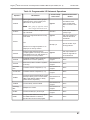
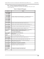
5.19 Programmable I/O Statements (Menu 18) . . . . . . . . . . . . . . . . . . . . . . 39
5.19.1 Stepping Through The I/O Program . . . . . . . . . . . . . . . . . . . . . 39
5.19.2 Program Operations . . . . . . . . . . . . . . . . . . . . . . . . . . . . . . . . . . 40
5.19.3 Changing The Program . . . . . . . . . . . . . . . . . . . . . . . . . . . . . . . 43
5.19.4 Leaving The I/O Program . . . . . . . . . . . . . . . . . . . . . . . . . . . . . 44
5.19.5 Factory Programmed Default I/O Program . . . . . . . . . . . . . . . . 45
5.20 Default Options (Menu 19) . . . . . . . . . . . . . . . . . . . . . . . . . . . . . . . . . 46
Section 6 Using the Model 5540 Downloading Software . . . . . . . . . . . . . . . . . . . . . 46
6.1 Starting and Ending . . . . . . . . . . . . . . . . . . . . . . . . . . . . . . . . . . . . . . . 46
6.2 Viewing Status . . . . . . . . . . . . . . . . . . . . . . . . . . . . . . . . . . . . . . . . . . . 46
6.3 Uploading Event Memory . . . . . . . . . . . . . . . . . . . . . . . . . . . . . . . . . . 47
6.4 Programming Procedure . . . . . . . . . . . . . . . . . . . . . . . . . . . . . . . . . . . . 47
6.4.1 Reprogramming the Options . . . . . . . . . . . . . . . . . . . . . . . . . . . 47
6.4.2 Printing the Options . . . . . . . . . . . . . . . . . . . . . . . . . . . . . . . . . . 48
6.4.3 Verifying The Selections . . . . . . . . . . . . . . . . . . . . . . . . . . . . . . 48
6.5 Programming the I/O Statements . . . . . . . . . . . . . . . . . . . . . . . . . . . . . 48
6.5.1 What The I/O Statements Do . . . . . . . . . . . . . . . . . . . . . . . . . . 48
6.5.2 I/O Programming Procedure-5540 Software . . . . . . . . . . . . . . . 51
iv
Regency® Model 4734 Access Control Expander Installation Manual (P/N 150807, Rev. A)
Revised 5/98
List of Figures
Figure 1
Model 4734 Installation . . . . . . . . . . . . . . . . . . . . . . . . . . . . . . . . . . . . . . . . . . . . . . . . 3
Figure 2
Model 4181 Connections . . . . . . . . . . . . . . . . . . . . . . . . . . . . . . . . . . . . . . . . . . . . . . . 5
Figure 3
1 1 TEST Menu Structure . . . . . . . . . . . . . . . . . . . . . . . . . . . . . . . . . . . . . . . . . . . . . 14
Figure 4
7 TEST Menu Structure . . . . . . . . . . . . . . . . . . . . . . . . . . . . . . . . . . . . . . . . . . . . . . . 15
Figure 5
Auxiliary Devices . . . . . . . . . . . . . . . . . . . . . . . . . . . . . . . . . . . . . . . . . . . . . . . . . . . 48
Figure 6
Connections to Terminals 15, 16, and 18 . . . . . . . . . . . . . . . . . . . . . . . . . . . . . . . . . 49
v
Regency® Model 4734 Access Control Expander Installation Manual (P/N 150807, Rev. A)
Revised 5/98
List of Tables
Table 1
Software Updates . . . . . . . . . . . . . . . . . . . . . . . . . . . . . . . . . . . . . . . . . . . . . . . 6
Table 2
Panic Key Zones . . . . . . . . . . . . . . . . . . . . . . . . . . . . . . . . . . . . . . . . . . . . . . . 8
Table 3
Touchpad Functions . . . . . . . . . . . . . . . . . . . . . . . . . . . . . . . . . . . . . . . . . . . . . 9
Table 4
Text and Characters . . . . . . . . . . . . . . . . . . . . . . . . . . . . . . . . . . . . . . . . . . . . 12
Table 5
Macro/Function . . . . . . . . . . . . . . . . . . . . . . . . . . . . . . . . . . . . . . . . . . . . . . . 13
Table 6
Default Mode Selections . . . . . . . . . . . . . . . . . . . . . . . . . . . . . . . . . . . . . . . . 19
Table 7
House Codes . . . . . . . . . . . . . . . . . . . . . . . . . . . . . . . . . . . . . . . . . . . . . . . . . 22
Table 8
Loop Response Times . . . . . . . . . . . . . . . . . . . . . . . . . . . . . . . . . . . . . . . . . . 26
Table 9
Zone Types . . . . . . . . . . . . . . . . . . . . . . . . . . . . . . . . . . . . . . . . . . . . . . . . . . 27
Table 10 Reporting Formats . . . . . . . . . . . . . . . . . . . . . . . . . . . . . . . . . . . . . . . . . . . . . 29
Table 11 Factory Programmed Messages . . . . . . . . . . . . . . . . . . . . . . . . . . . . . . . . . . . 32
Table 12 Test Day Choices . . . . . . . . . . . . . . . . . . . . . . . . . . . . . . . . . . . . . . . . . . . . . . 34
Table 13 Zone Types . . . . . . . . . . . . . . . . . . . . . . . . . . . . . . . . . . . . . . . . . . . . . . . . . . 36
Table 14 Programmable I/O Statement Operations . . . . . . . . . . . . . . . . . . . . . . . . . . . 40
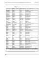
Table 15 Status and Port Addresses . . . . . . . . . . . . . . . . . . . . . . . . . . . . . . . . . . . . . . . 42
Table 16 Default I/O Program . . . . . . . . . . . . . . . . . . . . . . . . . . . . . . . . . . . . . . . . . . . 45
Table 17 Logical Operators . . . . . . . . . . . . . . . . . . . . . . . . . . . . . . . . . . . . . . . . . . . . . 50
Table 18 Arithmetic Operators . . . . . . . . . . . . . . . . . . . . . . . . . . . . . . . . . . . . . . . . . . . 50
Table 19 Programmable I/O Output Labels (Read/Write) . . . . . . . . . . . . . . . . . . . . . . 51
Table 20 Output Designations . . . . . . . . . . . . . . . . . . . . . . . . . . . . . . . . . . . . . . . . . . . 52
Table 21 Programmable I/O Status Labels (Read Only) . . . . . . . . . . . . . . . . . . . . . . . 53
Table 22 Zone Groups . . . . . . . . . . . . . . . . . . . . . . . . . . . . . . . . . . . . . . . . . . . . . . . . . 54
vi
Regency® Model 4734 Access Control Expander Installation Manual (P/N 150807, Rev. A)
Revised 5/98
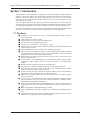
Section 1: Introduction
The Model 4734 Control Expander is a plug-on unit that provides greatly enhanced software
features, event storage memory, and user-friendly operation for the Model 4720 Control/Communicator. The 4734 replaces the control microprocessor on the 4720 (or on the obsolete
Model 4721 Area Control Software). It allows full use of up to two zone expanders for a system maximum of 80 zones.
The 4734 supports the Model 4181 (PL513) Power Line Control Interface, which controls X10 modules at various locations, making it possible to turn lamps and other appliances on and
off at preprogrammed times, as the result of touchpad key press or a change in system status.
The Model 4734 hardware is powered by the 4720 hardware and supports the same expansion
devices as the 4720. The 4734 can be added to existing 4720 (or 4721) installations.
1.1 Features
■
■
■
■
■
■
■
■
■
■
■
■
■
■
■
■
■
■
■
■
Availability of up to 1000 user codes (or cards) programmable to allow control of
selected functions.
1000 separate users, cards, or codes.
Allows door relays to be bypassed (or latched) open.
Any door can be controlled from any station.
Can report “Access Denied” or “Door Restore” events.
Support of up to 64 expansion zones which have all the same options as internal zones
(except fast loop restore).
Each touchpad panic zone is a separate zone, adding 64 more zones.
Ability to report up to 1000 user codes (or cards), programmable to allow control of
selected functions. Secondary user code (Code 2) option allows codes to be enabled
temporarily for users such as guests and baby-sitters.
High-security code option that requires selected users to enter a second code to gain
access to restricted areas.
32 time windows for programming time restrictions and automatic arming and disarming times. Time windows can also be used to activated X-10 or 4180 auxiliary
outputs.
Holiday schedule can be programmed for 16 holiday dates.
Two dates can be supplied to adjust automatically for daylight savings time.
Event memory that stores at least the last 500 events, including alarms, troubles,
bypasses, restores, openings, closings, and tests.
Use of both door/card access and intercom/phone modules on the same installation.
Each station is selected for either door or intercom operation.
Enhanced access control features such as separate “door access” and “door left open”
timers for each door.
Control of up to 32 standard X-10 Power Line Control Interface Modules. Outputs
can be activated by time events, zone status, alarms, touchpads, or virtually any internal condition or combination of conditions.
Support of two Model 4180 Status Display Modules for a total of 32 outputs that can
be programmed to annunciate status conditions such as armed, alarm, trouble, and
tests.
Built-in programmer with English-language prompts.
Fully programmable using built-in programmer or Model 5540 Downloading Software.
Enhanced split system (area control) capability, allowing separate control of system
functions in up to eight different areas of the building.
1
Regency® Model 4734 Access Control Expander Installation Manual (P/N 150807, Rev. A)
Revised 5/98
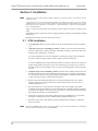
Section 2: Installation
NOTE
1. Because the 4724 and 4734 have different options, you cannot convert a 4724 into a 4734 by
replacing a chip.
2. The 4734 is for use with the 4720 Revision M circuit boards; the 4734-2 is for use with the
4720 Revision N or later circuit boards. When referring to both the 4734 and the 4734-2, these
instructions use the convention “4734/4734-2.” (The 4734/4734-2 cannot be used with Revision A-L 4720 boards.)
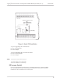
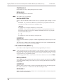
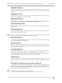
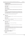
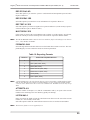
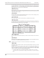
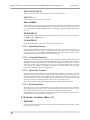
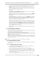
Figure 1 on the next page shows the placement of the 4734/4734-2 board in relation to the
4720.
The Model 4734N is a 4720 and a 4734-2 (shipped together), which has been partially installed
at the factory.
Maximum current draw for the 4734/4734-2 is 50 mA.
2.1 4734 Installation
1.
Very important. Remove power from the 4720 by disconnecting the AC power and battery.
2.
(Skip this step if you are installing a 4734N.) Carefully remove the 4720 control microprocessor chip from its socket by inserting a flat-blade screwdriver under each end of the
microprocessor and prying it out slowly.
If you are installing a 4734-2 board, which has a socket for this chip, press the chip into
the socket. Observe proper polarity (it is the opposite of the other large ICs).
If you are installing 4734-2 board which does not have a socket for this chip, the chip is no
longer needed because the 4734-2 has its own control chip. If you want to, you can save
the chip for later use (for example, in case you ever need to downgrade a 4734-2 back into
a 4720).
NOTE
2
3.
(Skip this step if you are installing a 4734N.) Insert the socket adapter into the 4720 control microprocessor socket. Pin 1 (marked on the adapter) goes in the upper left hand corner of the socket. Make sure all pins are aligned. Press adapter in, making sure the adapter
is fully seated (this requires a fair amount of pressure).
4.
Remove the lower left hand mounting screw from the 4720 panel. The screw will no
longer be used. (If an earth ground wire was attached at this screw move the wire to
another mounting screw.)
5.
Place the 4734/4734-2 circuit board over the pins on the socket adapter. The plastic
mounting bar should extend down over the mounting hole. Carefully press the 4734/47342 onto the socket adapter. The 4734/4734-2 will rest level on the 4720 with the mounting
hole aligned with the hole in the mounting bar.
6.
Fasten the 4734/4734-2 to the 4720 by placing the long 6-32 Phillips screw (provided)
through the mounting bar into the mounting hole and tightening the screw.
7.
Reconnect power to the 4720 and turn on. The normal power-up display is “Default in
250s. Press CLR.”
The 4791 EEPROM chip on the 4720 is not used by the 4734/4734-2 and may be removed if
desired. The 4734/4734-2 has its own EEPROM.
Regency® Model 4734 Access Control Expander Installation Manual (P/N 150807, Rev. A)
22
21
20
19
18
17
16
15
14
13 12
11
10
9
8
Revised 5/98
7
Model 4720
Adapter (P/N 130315 or 130316)
Pin 1
Model
4734/4734-2
**Control Chip
23
24
25
26
27
28
29
30
31
32
33
34
35
36
37
38
8457G19A.DSF
Figure 1: Model 4734 Installation
*If you are upgrading a Rev. M 4720 board:
Use 4734 Access Expander
Use 130315 Adapter
*If you are upgrading a Rev. N or later 4720 board:
Use 4734-2 Access Expander
Use 130316 Adapter
NOTE
*4720 board revision labeled on board
**4734 uses 50747 series control chip
4734-2 uses 38000 series control chip
2.2 Access Control
For access card performance with the 4734, use the Model 4420 Interface or 4660C touchpads
with card readers. Refer to the 4300 Installation and Operation Manual (P/N 150497) for
information on how to install the access control system.
3
Regency® Model 4734 Access Control Expander Installation Manual (P/N 150807, Rev. A)
Revised 5/98
2.3 Zone Expanders
For more information on wiring zone expanders, see the 4720 Installation Manual (P/N
150476).
In some situations, zone expanders operate differently with a 4734 system than they do with a
4720 only. The instructions below describe such differences (or refer to additional sources of
information).
2.3.1
Current Models
The 4115 Serial Zone Expander and 4126 Hardwire Zone Expanders are the models currently
available for use with the 4720. Each of these products has its own installation manual. The
4115 Installation Manual (P/N 150648) is shipped with the product; the 4126 Installation
Manual (P/N 150860) is part of the Regency Technical Documentation binder.
2.3.2
Older Models
The following information about zone expander models that are no longer available is retained
for installers who may need to troubleshoot or repair an existing system.
Model 4110 Serial Zone Expander
4110 zones using 4100 or 4101 sensors may be supervised, but the NO EOL option must be
selected as yes since the sensors have no end-of-line resistor. Two 4110 expanders may be
used for up to 120 additional serial zones.
Model 4125 Multiplexed Zone Expander
The 4125 is enhanced by the 4734 to allow zones to be wired like 4720 internal zones.
Normally Closed Zones must have either a 15 K end-of-line resistor in series with the contact
or, if not using a resistor, they must be programmed as NO EOL:YES.
Zones may be programmed as normally open and normally closed for UL type burglary zones.
Zones programmed in this manner must have a 15 K end-of-line resistor and must be programmed as NO EOL:NO. These zones may also have day supervision selected.
Two 4125 zone expanders may be used for up 128 added zones. Zones on the second expander
should be wired starting at Zone #1, the actual zone number will be offset by the number of
zones on Expander #1 plus the number of internal zones.
Model 4130 RF Zone Expander
4130 zones must be programmed as normally open on the 4734. The transmitters are then individually programmed as normally open or closed.
Two RF zone expanders may be used under special circumstances. Typically this would be
used in installations where the two receivers are isolated by some type of barrier wall which
blocks signals from the other expander.
NOTE
Using more than 64 total transmitters is not recommended.
2.4 Model 4181 X-10 Power Line Control Module
NOTE
The Model 4181 and the X-10 modules are for supplementary use only and are not UL Listed
as control unit accessories.
2.4.1
Installation
The optional Model 4181 X-10 Power Line Interface provides remote and automatic control of
lighting and appliances in an installation. When X-10 modules are used with the 4734, the control panel can provide automatic control based on internal status and key commands. The 4181
(PL513) allows the 4734 to support up to 32 of the X-10 light or appliance modules. The 4181
also provides the 4734 with power line synchronized real time.
4
Regency® Model 4734 Access Control Expander Installation Manual (P/N 150807, Rev. A)
Revised 5/98
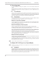
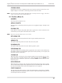
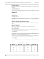
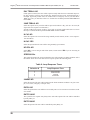
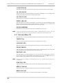
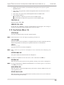
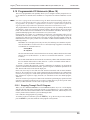
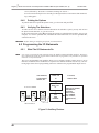
Plug the Model 4181 into a 120 VAC, 60 Hz wall outlet to the panel. Use a 4-wire modular
phone cable (P/N 130071, supplied) to connect the 4181 to the modular jack (P5) on the 4734
as shown in Figure 2. The maximum length of the cable is 20 feet. The 4181 is optically isolated from the powerline.
NOTE
The modular connectors on both the 4734 and the 4181 must NOT be connected to a phone
line or anything other than each other. The X-10 modules may be distributed throughout the
building.
To install the X-10 modules, plug them into outlets close to the appliances you want them to
control.
The 4181 LED is normally on when power
is applied. The LED flashes during transmission.
Model 4181
(PL513)
Power Line
Interface
M o d e l 4 7 2 0
Do not connect P5 to a phone line.
Modular Cable
P5
Model
4734/4734-2
8457G20A.DSF
Figure 2: Model 4181 Connections
5
Regency® Model 4734 Access Control Expander Installation Manual (P/N 150807, Rev. A)
2.4.2
Revised 5/98
Suppliers Of X-10 Modules
X-10 modules can be obtained from ITI. If you need to order X-10 modules, contact ITI’s Order Entry at
1-800-777-4841.
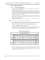
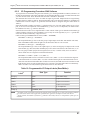
2.5 Software Updates
When placing the 4734 into an existing 4720 installation, you may need to replace the software (as shown in
the table below) to support the additional capabilities of the 4734. The 4734 can only be used with the 4720
Revision M circuit boards and requires the 9332 dialer chip, Revisions B or C. If you need to order a chip,
contact ITI Order Entry at 800-777-4841. The 4734-2 must use the 4720 Revision N board and requires the
9387 dialer chip.
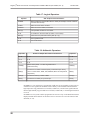
Table 1: Software Updates
If You Are
Using Device
Chip to Be
Replaced
Software Revision
Date Required
Socket Adapter
4734
9332
4720, Revision M
130315
4734-2
9387
4720, Revision N
130316
Section 3: 4734 Operation
This section describes operational features, other than programming, that are either unique to the 4734 or
that operate differently than they do with the 4720 and 4724. 4734 programming is described in Sections 4
through 6 of this manual.
3.1 System Power Up
At power-up (or reset), the touchpads show “default in 250s” on the first line and “Press CLR” on the second
line. This means that the system will go into Default Arm mode in the displayed number of seconds. The
number of seconds displayed changes as the system counts down the seconds before it enters Default Mode.
The first user to press CLR enters Set Time mode and the default countdown is canceled.
3.2 Access Control
3.2.1
Revision B Enhancements
Revision B (released October 1993) of the 4734 is greatly enhanced. It eliminates user traffic problems and
system busy conflicts that could occur in the previous revision. Multiple users can operate the system simultaneously from different touchpads. This feature is especially useful in large access or area systems where
users in different areas are not aware of each others’ activities. The following are highlights of Revision B
changes:
■ Status displays such as Event Memory, Not Ready Zones, and so on, can be viewed by different
users at the same time without interference. Users can access the system during the downloading.
During downloading, zone alarms are disabled temporarily to ensure that zone options are accurate,
but door access and status displays can be used while downloading is active.
■ Other users can access the system while one user is in Program Mode. For example, a user can
change system options at one station while other users are accessing doors or displaying status. As
in the previous revision, only one user at a time can access Program Mode. This prevents users
from making conflicting changes to the system or from using system resources that cannot be
shared.
6
Regency® Model 4734 Access Control Expander Installation Manual (P/N 150807, Rev. A)
■
3.2.2
Revised 5/98
In a large system or during heavy use, display response may be slower than normal.
For example, if 15 users are displaying Event Memory at the same time, the displays
will be slower than normal. Entry or exit delay displays may be updated less often
than once per second if the system is heavily loaded.
User Profiles
The 4734 controls system access through user profiles, which provide great flexibility while
simplifying access programming for end-users. User profiles are groups of options, time windows, and areas that can be assigned to users. Up to 16 profiles can reside in a system. This differs from the 4724, which assigns options individually for each code.
For example, User Profile #1 could be created for card-only, Time Window #1, Area #1 users.
Any time a user with these access needs is added to the system, User Profile #1 is selected
when the code is added to the system. User profiles for users needing greater access to the system can be created accordingly, making use of the 10 access options, (Arm, Disarm, Door,
Code2, Card-only, Bypass, Program, High Security, Time Windows, and Areas) available with
the system.
3.3 Area Control
An area is a part of a building that is being treated as a subsection of the total system. The
Model 4734 allows an installation to be divided into up to eight areas. The two levels of system
operation using areas are described below in Sections 3.3.1 and 3.3.2
3.3.1
Simple System
At this level of operation, the area programming is used only to divide system door access into
separately accessed areas. Codes and touchpads are programmed to determine which codes can
be used to gain door access at each touchpad. Arming and other functions operate at all stations
and apply to the entire system.
3.3.2
Split Arming
Split arming offers a high degree of independent operation for each area. Each area can be
independently armed and disarmed. Each area has its own entry and exit timer. Entry or exit
zones assigned to a particular area will be disabled during the entry or exit time for the area.
The programmed entry and exit times are shared by all areas.
Interior and instant operation are also controlled separately for each area. Each area has its own
interior zones and interior active status. Each area has its own instant status, which disables the
entry and exit timers for that area.
Code2 operation applies separately for each area. When the Code2 feature is activated, Code2
restricted access codes may disarm the area once. Normally Code2 restricted codes can never
disarm the system.
Each area can be armed and disarmed using only touchpads and codes that have been assigned
to the area.
3.3.3
Area Assignments
Each zone can be assigned to any one of the eight areas. Any number of zones may be assigned
to a particular area. Chime zones sound only at touchpads in the same area. Entry and exit
zones are also activated by area. There are separate entry/exit timers for each area.
Each code can be assigned to any or all of the eight areas. The code will only function at touchpads that are also assigned to the same area or areas.
Each touchpad can be assigned to one or more areas. More than one touchpad can be assigned
to each area. Each touchpad will display global system troubles and the status of any areas to
which it is assigned.
The Model 4180 Status Display Module can be programmed to activate speakers and bells for
alarm and trouble conditions that occur anywhere in the system or only for those that occur in
specific areas.
The only items that report by area are openings and closings.
7
Regency® Model 4734 Access Control Expander Installation Manual (P/N 150807, Rev. A)
Revised 5/98
3.4 Touchpad Operation
3.4.1
Touchpad Designations
The Model 4734 Access Expander allows the system to use both door/card access and intercom features in the same installation.
Each touchpad location (up to 15) has several programmable options. Touchpads designated as
door stations will allow codes to be used for door access. A programmable option allows single-swipe access and disarm at door stations. The EXIT feature on door access touchpads can
be programmed to generate a report and printout. Each card (code) must be assigned an area or
a group of areas to which it is granted access. The card will work only at stations that are
assigned to the same areas or group of areas.
Touchpads NOT selected as door stations will allow cards to be used for arming and disarming, but not door access. Cards swiped at these stations will arm or disarm the system, depending on the card's current privileges.
Touchpads designated as intercom stations will be able to use the intercom features, but will
not have door-access capabilities.
NOTE
Any station may access Model 4150 relays or X-10 modules.
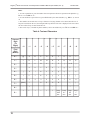
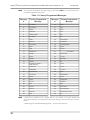
Alarms and touchpad troubles are defined by location. Panic keys report as separate zones for
each station. Duress alarms caused by entering the duress prefix also have a separate zone I.D.
for each touchpad. Table 2, below, lists the zone reported for each touchpad.
Panic Key zone numbers may be found in Table 2 or by using the following formula:
Zone = (STATION ID #) X 4 + 81 + KEYNUM
KEYNUM is 0 for DURESS, 1 for POLICE, 2 for AUXILIARY, and 3 for FIRE. The STATION ID is set to 0-15 by programming the EEPROM in the touchpad (Models 4660B/C/R) or
by using the DIP switches on the back of each touchpad (older touchpad models).
Table 2: Panic Key Zones
Zone Generated By Key
Key
Key
STATION:
0
1
2
3
4
5
6
7
DURESS
81
85
89
93
97
101
105
109
POLICE
AUX
FIRE
82
83
84
86
87
88
90
91
92
94
95
96
98
99
100
102
103
104
106
107
108
110
111
112
STATION:
8
9
10
11
12
13
14
15
DURESS
113
117
121
125
129
133
137
141
POLICE
AUX
FIRE
114
115
116
118
119
120
122
123
124
126
127
128
130
131
132
134
135
136
138
139
140
142
143
144
When one touchpad is in use and access is attempted at another location, the second location
will receive a “SYSTEM BUSY” message. However, the system will respond to a panic key
activation or exit request at the second location. Touchpads are assigned to a group of areas for
area control (see Section 3.3 of this manual).
8
Regency® Model 4734 Access Control Expander Installation Manual (P/N 150807, Rev. A)
3.4.2
Revised 5/98
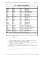
Touchpad Operation
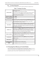
The Model 4734 Access Expander provides the following additional touchpad functions:
Table 3: Touchpad Functions
To gain access at a card reader or touchpad at a controlled access door,
just present the card or
press DOOR and enter the PIN at the touchpad.
DOOR ACCESS
To open a door at another station, press the number of the door and then
present the card or press DOOR and enter the PIN at the touchpad.
If High Security mode is used, the card must be presented first and then
the PIN is entered on the touchpad.
DISPLAY ALARMS
Press MEM.
DISPLAY TROUBLES
& SUPERVISORIES
Press STAT.
BYPASSING DOORS
To latch a door open or release the latch, press DOOR BYPS and then
present the card or enter the PIN on the touchpad. The touchpad will display “DOOR BYPASS” when doors are latched open. Doors remain
latched until they are manually unlatched.
4150 STATUS
To view the status of the analog inputs and relay outputs (controlled by the
Model 4150 Auxiliary Control), press 5 STAT. The analog inputs will be
shown on the touchpad display along with the programmed description. If
a 5260 printer is connected to the system (see Section 5.6 of this manual),
the status will also be printed.
TOGGLE X-10s
To toggle X-10 Modules on and off, press a number from 101-116 or
201-216, then * or CODE2 or DOOR, followed by 1 for ON and 0 for OFF.
Numbers 201-216 activate modules 1-16 from House Code 1. Numbers
from 201-216 activate modules 1-16 from House Code 2. The house
codes for each section are programmed into the EEPROM. The display
shows the actual house code and module address activated.
DISPLAY EVENTS
To display the event memory, press 1 MEM, then enter a START DATE to
begin the event display. Press the digits of the month, day, and year, then
press TEST. All events on or after this date will be shown. To show all the
events in memory, press CLR TEST.
CLEAR EVENTS
To clear the event memory, press 1 0 TEST and enter a code with Program Mode access. Press 1 to erase the memory, 0 to quit, and press
TEST to continue.
ZONE DISPLAY
Press 1 STAT to display all zone locations assigned to the same areas as
the touchpad.
TOUCHPAD DISPLAY
SOFTWARE REVISION
Press 2 STAT to view the touchpad location.
Press 4 STAT to view the 4734 software date.
3.5 Dumping Event Memory to Central Station
The 4734's event memory can be transmitted to the central station to be saved as a permanent
record. Currently, this must be done using the Model 5540 Downloading Software.
The 4734's event memory can be uploaded using a procedure similar to the one used to upload
programmed options. The procedure is explained in Section 6.3 of this manual.
9
Regency® Model 4734 Access Control Expander Installation Manual (P/N 150807, Rev. A)
Revised 5/98
3.6 Walk Test
The 4734 Walk Test mode allows the system to be tested without causing alarm reports. Follow the procedure below to perform a walk test.
1. Press 2 TEST followed by Code 0 or Code 1.
NOTE
2.
The display will show WALK TEST or your customized walk test message (see Section
5.12 of this manual).
3.
Arm individual areas or the entire installation. Then violate the sensors by walking
through the armed areas. The system will operate as normal except that it will not report
alarms to the central station, and alarm tones will not be sent to the external bell. The
alarm conditions will be displayed on the touchpad LCD and annunciated on the internal
speakers.
The system will remain in the same armed/disarmed state after you exit Walk Test Mode, so be
sure to arm or disarm it as desired.
4.
Interior zones may be armed or disarmed during the test to verify operation of the INT key
and options.
5.
Test the exit and entry zones to verify the delay times you have programmed.
6.
View the alarm memory to see that the desired areas have been activated.
7.
To exit Walk Test Mode, press MUTE MUTE on any touchpad.
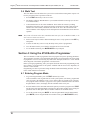
Section 4: Using the 4734 Built-In Programmer
The 4734 includes a built-in programmer that can program all system operating parameters.
The programmer is simple to use and includes help displays for entering data. The 4734's builtin programmer can be accessed using any 4000 series touchpad, Section 4.7 of this manual
shows diagrams of the built-in programmer’s menu structure.
Before you begin programming, write your option selections down in the programming record,
(P/N 150675). For descriptions of the options available with the 4734 Access Expander, see
Section 5 of this manual.
Programming can also be performed using the Model 5540 Downloading Software. See Section 6 of this manual for instructions.
4.1 Entering Program Mode
10
1.
To go into Program Mode, press 1 1 TEST followed by Code 0.
Code 0 (installer's code) is granted access to all system options. (The factory programmed
value for Code 0, the installer's code, is 1234.) Other codes are granted access to the first
four program menus if the PG or “program” access option is enabled for that code. When
Program Mode is active, the display lists the available menus one by one.
2.
Press the number of the menu that includes the options you wish to program. Press TEST.
The first line of the touchpad display will show the option name and the most recently programmed value for that option. The second line will show the available choices.
3.
To exit the current menu, press MUTE. To leave Program Mode from the main manual,
press MUTE; to leave Program Mode from within a menu, press MUTE MUTE (twice).
Regency® Model 4734 Access Control Expander Installation Manual (P/N 150807, Rev. A)
Revised 5/98
4.2 Stepping Through the Program
By pressing TEST, you can view the current option settings in a menu. The option description
appears on the top line, followed by the current setting. The bottom line shows which keys can
be used at that step of the program. In some cases, the key name will be followed by a word
that explains how the key is used.
EXAMPLE: TEST - ENTER means you use the TEST key as you would use the
ENTER key on a computer, to enter data into the program.
Press TEST again to proceed to the next option without changing the one you just viewed.
Some of the menus (ACCESS, for example) repeat options for many numbered items. The first
step in the loop may allow you to choose which numbered item you wish to program. The
menu will automatically advance to the next numbered item when it reaches the end of the
options for the current item.
4.3 Programming the Options
For some options, the available choices are numbered and appear on the bottom line of the display. To program an option, key in the number of the desired choice. The top line of the touchpad display will show the new value.
For YES/NO options, press 0 for NO and 1 for YES.
Press TEST. The display will advance to the next option.
4.4 Correcting Errors
To CORRECT AN ERROR you made or to clear displayed data, press CLR. The LCD will
show “0” or the first choice. Enter in the correct data, then press TEST.
To restore factory default data, press the CHM key. This will cancel the new data and restore
the default data. Press the TEST key to advance to the next option.
NOTE
The CHM key will restore the factory-programmed default value to any option.
4.5 Entering Text
There are several menus that require text and other characters to be entered (for example, zone
location descriptions). The display will show the current programmed text on the first line of
the display, with an underscore character (or “cursor”) denoting the end of the programmed
text. The second line will show the option name momentarily, followed by numbered groups of
symbols.
4.5.1
General Form
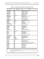
To enter text or characters, follow the procedure below and refer to Table 4.
1. Find the character you want in the area below and to the right of the double lines.
2.
Press the digit to the left of the vertical double line in the same row.
3.
Press the digit above the horizontal double line in the same column.
The character will appear on the top line of the display. Continue selecting characters this
way, until you have finished programming the message.
To erase the last character, press STAT. Pressing BYPS will move the cursor to the right,
entering a blank space after the last character. Pressing CLR will erase the text and place
the cursor at the beginning of Line 1.
If you select the wrong group of letters when you press the first digit, press MUTE or
CLR to return to Step 2.
11
Regency® Model 4734 Access Control Expander Installation Manual (P/N 150807, Rev. A)
Revised 5/98
Hints:
1. To enter capital letters, press the number that corresponds to the letter's position in the alphabet. e.g.,
0 1 for “A” and 2 6 for “Z.”
2. To enter numbers as part of the text, press 6 followed by the desired number, e.g., 6 0 for “0,” and so
on.
3. The numbers 96-99 will cause a “beep” character of varying duration to be entered into the text. If
beeps are inserted into the text, the touchpad will beep whenever the text is displayed. The cursor does
not move when a beep is entered into the text.
4. The # and * keys, if needed for phone numbers, can be entered directly. Use 7 3 for # and 8 0 for *.
Table 4: Text and Characters
Second
Digit
(To
Right)
...0
...1
...2
...3
...4
...5
...6
...7
...8
...9
0...
@
A
B
C
D
E
F
G
H
I
1...
J
K
L
M
N
O
P
Q
R
S
2...
T
U
V
W
X
Y
Z
[
\ or ¥
]
3...
‘
a
b
c
d
e
f
g
h
i
4...
j
k
l
m
n
o
p
q
r
s
5...
t
u
v
w
x
y
z
{
|
}
6...
0
1
2
3
4
5
6
7
8
9
7...
(blank)
!
“
#
$
%
&
’
(
)
8...
*
+
,
-
.
/
:
;
^
_
→
←
<
=
>
?
beep
0.05
sec.
beep
0.1
sec.
beep
0.5
sec.
beep
1
sec.
First
Digit
(Below)
9...
12
Regency® Model 4734 Access Control Expander Installation Manual (P/N 150807, Rev. A)
4.5.2
Revised 5/98
Display Macros
There are several “macro” message characters that activate special displays and may be embedded within
any message. Be aware that the displays take a certain number of characters each.
When using the 5540, the macro characters are preceded with a \ (backwards slash) character. In the built-in
programmer, macro characters are preceded by the character ¥. To enter this character, press 2 8 on the
touchpad.
Table 5: Macro/Function
Macro
Function
Display
Width
\T
TIME
DAY HH:MM AM
9 + day field
\M
24HR TIME
DAY HH:MM
6 + day field
\D
DATE
MM/DD/YY
8
\E
DATE (European format)
DD/MM/YY
8
\A
ARMED AREAS
12345678
8
\R
READY/NOT READY
READY, NOT READY, READY 12345678
(N/A)
EXAMPLE: To display ARMED with the armed areas on line one of the LCD, enter ARMED:\A for
System Message #57. To display DATE with the current date on Line 2, enter DATE:\D for System
Message #58.
As you are programming, you will see the shortened form of the message. During normal use, the actual,
non-abbreviated message will appear.
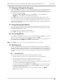
4.6 Programming Secret Codes or Cards
This menu is useful if you only want to change secret codes without going through all the options in the
CARDS/CODES Menu (Menu 1). See Section 5.2 of this manual for more information. To access the
SECRET CODES Menu, press 7 TEST then enter Code 0 or Code 1, other codes may be used, but they
must have PROGRAM selected in their user profile and they will only program codes with higher ID’s.
4.6.1
Loading Cards
After 7 TEST is entered, the prompt “BULK LOAD?-YES/NO” appears. Select yes if you will be loading
access cards which will all be using the same user profile. For loading cards by swiping, the card reader must
be connected to the same touchpad that Program Mode is activated from. Alternatively, the 4420 Card Interface can temporarily be set to the same station ID as the touchpad where Program Mode was activated.
After selecting BULK LOAD, select the first code ID slot to program at the “CODE#:0” prompt. Codes will
be programmed into successive ID slots. At the “PROFILE#0:0” prompt, select the profile number that will
be used for the card block being loaded. All cards will be assigned to the same profile as entered here. After
pressing TEST, begin presenting cards to the card reader, until all cards are programmed. After the last card,
press MUTE MUTE to exit Program Mode.
4.6.2
Loading Individual Secret Codes Or Cards
If BULK LOAD mode is not selected, each code entered will also require the user PROFILE to be entered.
Each code may be assigned a different profile.
13
Regency® Model 4734 Access Control Expander Installation Manual (P/N 150807, Rev. A)
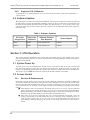
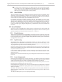
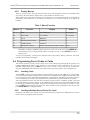
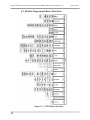
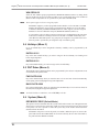
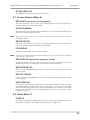
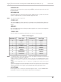
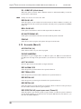
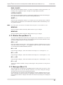
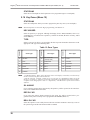
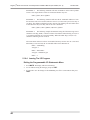
4.7 Built-In Programmer Menu Structures
Figure 3: 1 1 TEST Menu Structure
14
Revised 5/98
Regency® Model 4734 Access Control Expander Installation Manual (P/N 150807, Rev. A)
Revised 5/98
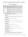
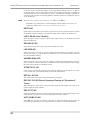
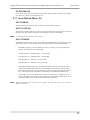
7 TEST
#0CODE
#1CODE
. . .
8457G31A.DSF
Figure 4: 7 TEST Menu Structure
Section 5: Programming Options Description
This section explains the options that can be programmed for the 4734. The options are listed
here are as they appear on the touchpad display when the built-in programmer is used. The
menu structure for the Model 5540 Downloading Software is slightly different. The selections
shown below are the factory-programmed default values.
NOTE
This section shows ALL of the available options. However, some options will determine
whether or not another option is available.
EXAMPLE: If you selected NO for the AUTO TEST option, the DAILY TEST, TEST
DAY, and TEST TIME options will not function.
Before you begin programming, read through the options, then write down the selections you
plan to make in the programming record (P/N 150675). The procedure for using the built-in
programmer is explained in Section 4 of this manual. Instructions for using the Model 5540
Downloading Software can be found in Section 6 of this manual.
NOTE
1. After installing the 4734, you must reprogram all the options, even if the options had been
programmed previously. This is because the 4720 EEPROM, on which the options were originally programmed, is no longer used.
2. When the 4734 is installed, options can be programmed using the 4734’s built-in programmer (accessed through any 4000 series touchpad) or the Model 5540 Downloading Software.
The Model 5520 Desk Top Programmer cannot be used with the Model 4734.
5.1 Time Windows (Menu 0)
The 4734 provides 32 available time windows (time periods), each specified by days of the
week and a starting and ending time. Each access code can be programmed to be used during
any combination of the 32 time windows (PROFILES, Menu 2).
Opening and closing can be enabled by a programmed combination of the 32 time windows.
Each time window can also be enabled on holidays. Up to 16 calendar days can be designated
as holidays (HOLIDAYS, Menu 3).
For auto-arming, there is a programmable delay period during which the user may extend the
delay or cancel the auto-arm. During the delay, the time remaining will be displayed at the
touchpads along with an audible warning. This delay is programmed in TIMERS (Menu 13).
These features replace the NORMAL/SPECIAL and CLOSED DAYS option previously used
with the 4720. Time windows can be programmed by the end-user to provide optimum system
flexibility.
NUMBER:#0
Select the time window to program.
15
Regency® Model 4734 Access Control Expander Installation Manual (P/N 150807, Rev. A)
Revised 5/98
START#0:00:00
Using military time, key in the beginning time for the window.
END#0:00:00
Key in the ending time for the window.
NOTE
Time windows may cross midnight.
DAYS#0:SMTWTFSH
Select the days on which the window will be active by toggling the digits 0 through 7 on and
off.
EXAMPLE 1: If you want Time Window #0, which has been programmed to last from
7:00 AM to 8:30 AM, to be in effect on weekdays, select:
-MTWTFby toggling keys 1 through 5 ON and keys 0, 6 and 7 OFF.
EXAMPLE 2: If you want Time Window #3, which has been programmed to last from
8:00 AM to 9:00 AM, to be in effect on Sundays and holidays, then when you program
DAYS#3:SMTWTFSH, select:
S------H
by toggling keys 0 and 7 ON and keys 1 through 6 OFF.
NUMBER:#1
Select the next time window to program. Continue programming the options for up to 32 time
windows.
The easiest way to disable a time window is to go to the DAYS option (TIME WINDOWS,
Menu 0) and deselect all days by pressing CLR TEST.
5.2 Codes/Cards (Menu 1)
Secret codes or cards and profile assignments can be programmed by the end user.
NOTE
1. The programming steps for Code 0 (installer’s code) and Code 1 (main user’s code) profiles
have no effect because they are fixed. Code 0 can always activate all features and can program
all options. Code 1 can activate all control functions (arming, disarming, bypassing, etc.), and
can program all user-programmable options.
2. Built-in programmer Menu 1 (Codes/Cards) is the same as the menu accessed with 7 TEST.
BULK LOAD:NO
Select YES if you will be loading cards which will all be using the same profile. Select NO if
you will be manually entering secret codes or if you are entering codes that will each have different profiles.
NUMBER:#2
Select the access code for which you want to program the options. Enter the identifying number—Code 2, Code 3, etc.—not the secret code. The code range is 0-999.
PROFILE#2:0
Select one of the 16 user profiles for this access code. If Bulk Load was selected, this profile
will be used for all codes entered.
16
Regency® Model 4734 Access Control Expander Installation Manual (P/N 150807, Rev. A)
Revised 5/98
CODE#2:000000
Program the secret code or card PIN for this access code. The code can be from four- to sixdigits in length. If a card reader is connected, present the card to the reader.
NOTE
Do not begin any codes with the same digits that are used for the duress trigger. The duress
trigger is programmed under SYSTEM (Menu 5).
5.3 Profiles (Menu 2)
NUMBER:
Select the profile to program (0-15).
ARS#0:12345678
Select the areas to which this profile may gain access by toggling the digits 1 through 8 ON
and OFF.
DOOR#0:YES
If this option is selected, this profile will be able to gain access to doors (within the areas
selected in the previous option). Press 0 for NO, 1 for YES.
NOTE
The 4734 is not UL Listed for door access control.
BYPASS#0:YES
If this option is selected, this profile will be able to bypass (disable) intrusion zones.
ARM#0:YES
This option enables the profile to be used to arm (close) the system.
DISARM#0:YES
This option enables the profile to be used to disarm (open) the system.
PROGRAM#:YES
This option enables users with this profile to program the secret codes for codes with the same
ID or higher, and the user-programmable options (time windows, holidays, access options, and
daylight-savings time adjust dates).
CODE#0:NO
When this option is selected, the codes using this profile become restricted codes for use by
guests, baby-sitters, and other temporary users. This means that when the CODE2 key is
pressed, the code can disarm the system once. Normally, CODE2 restricted codes can never
disarm the system.
HIGH SEC#0:NO
When this option is selected, codes using this profile become high security codes. For Door
Access codes, which are high security require the code to be first entered with a card. Then the
user must enter the PIN of the card on the touchpad before access is granted.
CARD ONL#0:NO
The card only option allows access to a door to be gained only by a card, not by a touchpad.
The high security option overrides this option, because it requires that both presenting the card
and entering the PIN at the touchpad.
17
Regency® Model 4734 Access Control Expander Installation Manual (P/N 150807, Rev. A)
Revised 5/98
WIN GRP#0:32
Select the time window group (programmed in WINDOW GROUPS, Menu 11) during which
this user profile may be used. To make it possible to use a profile all the time, select ALWAYS
(3 2). To make it impossible to use a profile at any time select NEVER (3 3).
NOTE
These options apply to all users using this profile.
EXAMPLE: Suppose you have programmed Time Window #1 for 8:00 AM to 5:00 PM
Monday through Friday, and you have programmed Time Window #2 for 10:00 AM to
5:00 PM on Saturdays (TIME WINDOWS, Menu 0). Then, suppose you have assigned
Windows #1 and #2 to Window Group #4 (WINDOW GROUPS, Menu 11).
If you want the code to be able to gain access and/or use a touchpad during the times from
8:00 AM to 5:00 PM on weekdays, and from 10:00 AM to 5:00 PM on Saturdays, then
select 4 for the WIN GRP option. Any group may be assigned to any profile and to more
than one profile. A profile may be assigned to only one window group.
5.4 Holidays (Menu 3)
Up to 16 calendar days can be designated as holidays. Holidays can be programmed by the
end-user.
DATE#1:01/01
Key in the date (month and day) you want to assign as the first holiday. Use leading zeros
before single-digit data.
DATE#2:01/01
Key in the month and day you want to assign as the second holiday.
5.5 DST Dates (Menu 4)
The daylight savings adjustment dates can be programmed by the end-user. Adjustments occur
at 2:00 AM on the specified date.
FWD DATE:00/00
Key in the month and day when you want the time to be set one hour forward automatically,
for the spring (forward) daylight-savings time adjustment.
BACK DATE:00/00
Key in the month and day when you want the time automatically to be set one hour back, for
the fall (back) daylight-savings time adjustment.
NOTE
To disable holidays or DST dates, enter 0 0 / 0 0 for the date.
5.6 System (Menu 5)
DEF/MODE:FORCE (Default Mode)
This option is used to determine what the system will do when it times out of Program Mode or
when power is restored to the panel. This would occur after power has been lost, then restored
to the panel, if no one is present to control the system. Key in the number shown beside the
desired selection in Table 6.
EXAMPLE: All power is lost at the panel (AC and DC). When the power is restored, the
panel will enter the SET TIME Mode. If no action is taken by the user after four minutes,
the panel will enter DEFAULT Mode.
18
Regency® Model 4734 Access Control Expander Installation Manual (P/N 150807, Rev. A)
Revised 5/98
Table 6: Default Mode Selections
Selection
Default Mode
0
The system will default to the DISARMED mode and will NOT generate an
Open Report to the central station.
1
The system will default to the DISARMED mode and WILL generate an Open
Report.
2
The system will default to the ARMED mode and will automatically bypass
(shunt) any zones that are not ready to be armed. The system will also generate a Close Report.
3
The system will default to the ARMED Mode. If any zones are not ready to be
armed, they will go into the ALARM condition and the appropriate report will be
sent to the central station. If all of the zones are ready, only a Close Report will
be generated.
BELL TST PU:NO (bell test at power-up)
This option causes the system to sound a two-second bell test whenever the system is reset.
DIALER:YES
The dialer must always be selected for normal operation. It can be disabled for troubleshooting
or while training end users. When the dialer is disabled, there is no battery or AC detection.
PRINTER:NO
Select this option if you are using a Model 5260 Printer Interface.
ZONE EXP1:NO
If at least one zone expander is to be used with the system, this option must be selected.
ZONE EXP2:NO
If two zone expanders are to be used with the system, both ZONE EXP1 and ZONE EXP2
must be selected.
INTERCOM:NO
Select this option if you are using the Model 4140 Intercom Module.
AUX CONTROL:NO
Select this option if you are using the Model 4150 Auxiliary Control Module.
INTERN ZONES:16
Select the number of internal zones used (zones built into the 4720 panel). This will let the system know where to start the expansion zones.
EXP ZONES#1:0
Enter the number of zones on Expander #1.
RESD CODE#1:0123
Select the residence code to be used with RF Zone Expander #1. This code must be the same as
the residence code programmed into the transmitters; see the section on expansion zones in the
4720 Installation Manual (P/N 150476). Skip this step if NOT using an RF zone expander.
19
Regency® Model 4734 Access Control Expander Installation Manual (P/N 150807, Rev. A)
Revised 5/98
EXP ZONES#2:0
Enter the number of zones used on Zone Expander #2.
RESD CODE#2:0223
If Zone Expander #2 is an RF zone expander, enter its residence code. Skip this step if NOT
using an RF zone expander.
ARM MENU:NO
Causes the Interactive Arm Menu, normally used in split arm systems, to be active in all systems when a code is entered.
INST INTR:NO
When this option is selected, all delayed zones become instant zones whenever any intrusion
alarm occurs.
FORCE ARM:NO
This option causes any zones that are not ready to be bypassed (shunted) when the system is
armed. Upon arming, the 4734 will generate a “CF” (Forced Closing) Report.
NOTE
Since Force Arming may automatically cause zones to be bypassed, the AUT UNBYPASS
option should be selected if the FORCE ARM option is enabled.
INTR INTRU:NO
When this option is selected, all interior zones will automatically be enabled when there is an
intrusion alarm.
INTR FLWRS:NO (Interior followers)
Selecting this option causes interior zone annunciations and reports to be delayed when an
entry zone is violated.
INTR LOCK:NO
This option disables the INT and DLY keys whenever the system is armed (after the exit
delay). This prevents anyone from disabling the interior zones while the system is armed.
AUT INTR OFF:NO
When selected, this option will automatically disable the interior zones when the system is disarmed.
AUT INTR ON:NO
When selected, this option will automatically disable the interior zones when the system is disarmed.
EXIT BEEPS:NO
This option causes an audible warning tone to be sounded during the exit delay.
SIL NGHT TRB:NO
When this option is selected, audible trouble tones will not be sounded while the panel is
armed.
20
Regency® Model 4734 Access Control Expander Installation Manual (P/N 150807, Rev. A)
Revised 5/98
KEY BEEPS SPK:NO
If the installation includes a touchpad without a PZT beeper, you can use this option to send
the beeps from the touchpad to the internal speakers; however, they will sound at all internal
speakers.
E/E BEEP PZT:YES
Select this option if you wish to have the entry/exit tones sounded on the PZT beeper. (These
tones are always audible on the internal speakers.)
SWINGER BYPS:YES
When this option is selected, the system will automatically bypass any zone that generates four
alarms within a specified time period (programmed in TIMERS, Menu 13).
DELAYED BYPASS:YES
When this option is selected, the system will not report bypasses to the central station, until the
panel is armed.
AUT UNBYPASS:NO
This option will automatically unbypass the bypassed zones when the panel is disarmed, to
allow trouble conditions to be reported.
NOTE
Since force arming may automatically cause zones to be bypassed, the AUTO UNBYPASS
option should be selected if the FORCE ARM option is enabled.
BYPASS CODE:NO
Selecting this option makes it impossible to bypass or unbypass a zone without first entering an
access code, even if the panel is disarmed.
REP BYPS ID:NO
When this option is selected, the user ID will be reported when anyone bypasses a zone. This
will only occur if the option BYPASS CODE has been selected. (Currently, the Model 9000
does not support this feature.)
ACCESS WINDW:NO
If this option is selected, all access codes are restricted to the time windows that have been
assigned to them (PROFILES, Menu 2). Selecting NO disables all time restrictions.
If you will be using access windows, see Section 5.2 of this manual. The access windows
restrict all functions that require an access code to certain times and days.
CHIME PZT:NO
When this option is selected, the chime tone will be heard at all touchpads assigned to the same
area as the chime zone. (If this option is not selected, the chime will be heard only at the speakers.)
MAX SKEY ID:1 (Maximum Supervised Touchpad ID)
For this option, enter the highest touchpad ID number that will be supervised. Touchpads with
higher numbers may be used, but they will not display area entry/exit or LED information. You
must give your supervised touchpads ID numbers in sequential order, starting at 1; see the
Model 4720 Installation Manual (P/N 150476).
NOTE
1. Touchpads must be supervised to be fully functional.
2. Stations with higher ID numbers can still be used, but will not be supervised.
21
Regency® Model 4734 Access Control Expander Installation Manual (P/N 150807, Rev. A)
Revised 5/98
DISPLAY RATE:3s
Select a speed in the range of 1-4 seconds. This option controls the rate at which all displays
are updated.
FAST RESTORE:NO
When this option is selected, the system reports restores as soon as the alarm has been restored,
instead of waiting for the shutdown time.
DURESS:NO
This option allows the use of the 4734’s DURESS feature. The duress trigger is a two-digit
code that the user can enter to notify the central station that an intruder has forced the user to
enter an access code.
DURESS TRIG:99
If the DURESS option has been selected, you must enter a one- or two-digit code that will activate a duress alarm. The digits entered MUST NOT be the same as the beginning digits of an
access code.
RING B CLOSE:NO (Ring Back at Closing)
When this option is selected, there will be a short bell test after kiss-off when a Closing Report
is sent.
BELL TST ARM:NO
Selecting this option causes a two-second bell test every time the system is armed.
AUX CODE:NOW
When this option is selected, it will be necessary to use an access code to toggle auxiliary control (discontinued Model 4150) relays or X-10 modules.
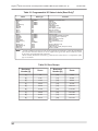
X-10 HC 1:A
This option allows you to choose the house codes for the first 16 of the 32 allowable X-10
modules. There is a choice of 16 letters, from which one house code can be selected for this
option. Enter the number next to the desired letter in Table 7.
The house code you select should be different from those of any other X-10 modules that may
be in the building that you do not wish to be connected to the 4000 system.
X-10 HC 2:B
Select the second house code. This house code will apply to the last 16 of the 32 allowable X10 modules.
Table 7: House Codes
22
Selection
House Code
Selection
House Code
0
1
2
3
4
5
6
7
A
B
C
D
E
F
G
H
8
9
10
11
12
13
14
15
I
J
K
L
M
N
O
P
Regency® Model 4734 Access Control Expander Installation Manual (P/N 150807, Rev. A)
Revised 5/98
NO PULS BELL:NO
Select yes for steady fire bell output. (Used for strobes.)
5.7 Access Options (Menu 6)
REP DG:NO (report door access granted)
This option causes the system to send a report indicating that the door was accessed using a
valid code number. The event is also printed.
DOOR DISARM:NO
This option causes the areas assigned to a particular access code to disarm automatically when
door access is granted to that access code.
NOTE
This option is effective only if the code has been programmed with the capability to disarm
(PROFILES, Menu 2).
REP/PR EXIT:NO
This option causes all door exit events to be printed and reported to the central station. Exit
requests are printed and reported as DOOR ACCESS ID 0.
PR DOOR:NO
This option causes all door access events to be printed.
NOTE
If you also select REP DOOR (ACCOUNTS, Menu 9), door access events will be printed and
reported to the central station.
REP DO/DF:NO (report door open/door forced)
Selecting this option causes the system to send a report every time the door sensor is violated
without using door access. It will report if the door is forced open or left open.
REP DOOR RST:NO
Select to report DOOR RESTORE events to the central station. This option requires a 9000
receiver upgrade.
REP ACC DEN:NO
Select to report ACCESS DENIED events to the central station. This option requires a 9000
receiver upgrade.
HIDE CODES:NO
If this option is enabled, users cannot see all codes when programming new codes. Codes with
programming ability can change secret codes, but they will see “*****” in place of the digits
of the code. This feature applies only to codes 2-255. When the Code 0 and Code 1 are used to
program codes, the digits of the code(s) will display. (This option is new with the 4734-2,
Revision C2 or later.)
5.8 Dialer (Menu 7)
COMP PH
If you will be using the downloading feature, you must enter the phone number that the computer will be connected to. The number entered may be up to 16-digits long.
23
Regency® Model 4734 Access Control Expander Installation Manual (P/N 150807, Rev. A)
Revised 5/98
If a pause is needed, such as after dialing “1” for a long distance number, enter an “A” (0 1). If
an internal phone system is being used in which you must dial a special digit to establish an
outside line (and wait for a second dial tone), enter a “D” (0 4) after the digit to establish the
outside line. The procedure for entering alphabetic and other characters is explained in Section
4.5 of this manual.
NOTE
The # and * keys cannot be entered directly. Use 7 3 for # and 8 0 for *.
EXAMPLE: If you must dial “9” before dialing the outside number of 555-3333, you
would enter “9D555-3333,” or “6 9 0 4 6 5 6 5 6 5 6 3 6 3 6 3 6 3.”
RETRY:NO
If this option is selected the system will try again to send a report 15 minutes after it has failed
its maximum number of attempts. If it fails all attempts again, it will not try another time.
LINE 2 EN:NO (Line 2 Enable)
Select this option if you are using two phone lines (requires the use of the Model 4175 Dual
Phone Line Monitor).
GROUND ST:NO
Select this option if you are using a ground start telephone network.
LINE MON:NO
Select this option if you will be using the Model 4175 Dual Phone Line Monitor. You can
monitor Line 1 only, if you do not have a second phone, but you cannot have both a monitored
line and an unmonitored line.
ANSWER RING:YES
Select this option if you wish to have the computer call the panel and download in the same
call. If you do not select this option, the communicator will wait until the phone stops ringing,
then dial up the computer for maximum security.
STORE OP/CL:NO
If this option is selected, the system will store opening and closing events until the next report
is sent. At that time, it will transmit all the events to the central station.
REP ALL O/C:NO
This option causes the system to report all openings and closings.
REP EXC O/C:NO (Report Openings/Closings at “Exceptional”
Times)
When this option is selected, the system will report openings and closings only if they occur
outside of specified time windows.
REP OT/CT:NO
Selecting this option causes the system to send an Open Trouble or Close Trouble Report to the
central station, if you fail to arm or disarm during a specified time window.
AUTO DUMP CS:NO
Select NO. This option is not available. Currently, the 5540 Downloading Software must be
used to dump event memory to the central station (see Sections 3.5 and 6 of this manual).
24
Regency® Model 4734 Access Control Expander Installation Manual (P/N 150807, Rev. A)
Revised 5/98
UP/DOWNLOAD:YES
Select YES to enable remote uploading and downloading. When the panel receives a signal for
downloading it will dial the computer phone number and use the account number that is programmed for Account #4.
FAIL ATTM:5
Enter the number of attempts (1-15) that the communicator will try to dial out before it gives a
dialer-failed signal.
TOTAL ATTM: 10
Enter the overall number of attempts (1-15) that the communicator will try to dial out using all
phone numbers. Select 0 for both FAIL ATTM and TOTAL ATTM for a local-only system.
# RINGS:1
This option is used in conjunction with the downloading feature. You would program the number of times (1-15) that your phone will ring before the communicator will dial out or answer
for downloading information. If you do not wish to use this feature, enter 0. If you also
selected ANSWER and REP, ALL O/C, the panel will answer after four fewer rings (than the
programmed number) if the system is armed (but see the note below).
NOTE
The panel will never answer unless it detects at least two rings.
LOW AC:4h
For this option, program the number of hours (1-15) that the AC power must be OFF before a
Low-AC Report is generated.
DTMF L1:NO
If this option is selected, Line 1 will use Touch-Tone® dialing. If you do not select this option,
the phone line will use rotary type dialing only.
NOTE
If you have selected DTMF L1, the dialer will alternate between Touch-Tone® and rotary dialing on subsequent attempts.
DTMF L2:NO
If this option is selected, Line 2 will use Touch-Tone® dialing.
DTMF ONLY:NO
If this option is selected, Touch-Tone® dialing will be used any time the system is dialing out.
ALT ANS BYP:NO
If this option is selected, an alternate method of answering machine bypass is used. To contact
the panel, dial the panel and hang up after hearing one ring. Redial the panel immediately
(within 30 seconds) and the panel will answer on the first ring. Use this option in situations
where the default answering machine bypass will not work.
DTMF RX:NO
This option is for future expansion. Select NO at this time.
5.9 Zone Options (Menu 8)
ZONE:#1
Select the zone for which you want to reprogram the options.
25
Regency® Model 4734 Access Control Expander Installation Manual (P/N 150807, Rev. A)
Revised 5/98
DAY TRBL#1:NO
If this option is selected, the zone will be supervised only while the zone is disarmed. Day trouble loop response is always .062 seconds. Day Troubles will not restore, until silenced from a
touchpad. Typical day trouble zones are window foils or emergency exits. If you select DAY
TRBL for a zone, you must also select N.C. for that zone. Do NOT pick both 24HR TRBL and
DAY TRBL.
24HR TRBL#1:NO
Select this option for any zone that will be supervised 24-hours a day, such as a fire zone (all
supervised zones require 15 K ohm EOL).
24-hour trouble loop response is always 10 seconds. A 24-hour trouble will restore as soon as
the loop is restored. Do NOT pick both 24HR TRBL and DAY TRBL.
N.C.#1:NO
Select this option if the zone will be using normally closed contacts (all N.C. zones require a
15 K ohm EOL).
N.O.#1:YES
Select this option when the zone will be using normally open contacts.
NO EOL:NO
Select NO if you are using an end-of-line (EOL) resistor. Select YES if you are not using an
EOL resistor.
SPEED#1:06s
This option determines the speed at which the zone will respond to an alarm condition. Select
the number shown next to the desired zone response speed in the following table.
Table 8: Loop Response Times
Selection #
Loop Response Time
0
1
2
3
0.010 seconds
0.062 seconds
1 second
10 seconds
24HR#1:NO
Select this option if the zone will be monitored for alarm conditions 24-hours a day (for example, if it is a fire, emergency or tamper zone).
EXIT#1:NO
Select this option if the zone will have an exit delay time or if it is an interior zone that is in the
exit corridor.
ENTRY1#:NO
The system has two separate entry delay times. Select this option if the zone will be controlled
by Entry Delay #1.
ENTRY2#:NO
Select this option if the zone will be controlled by Entry Delay #2.
26
Regency® Model 4734 Access Control Expander Installation Manual (P/N 150807, Rev. A)
Revised 5/98
INTERIOR:NO
Interior zones can be bypassed as a group using the INT key. Select this option if the zone will
be an interior zone.
BYPASS#1:NO
Select this option if you want to be able to bypass (shunt) the zone. If you do not select this
option for a particular zone, you will not be able to bypass that zone.
NOTE
Fire zones must NOT be bypassable.
CHIME#1:NO
This option enables the chime function for a particular zone. When the chime function is
enabled, the CHM key can be used to turn a door chime on and off when the system is disarmed.
AREA#1:1
Key in the number of the area to which you want to assign the zone. A zone can be assigned to
only one of eight areas.
TYPE#1:FIRE
Enter the number corresponding to the desired zone type in the following table.
Table 9: Zone Types
Selection #
Zone Type
Selection #
Zone Type
0
HOLDUP
8
WATER
1
FIRE
9
HEAT
2
EMERGENCY
10
COLD
3
PANIC
11
LOCAL
4
BURGLARY
12
UNUSED
5
TAMPER
13
DOORBELL
6
SUPERVISORY
(formerly GAS)
14
UNUSED
7
UNDEFINED
15
UNUSED
NOTE
1. Undefined, Water, Heat, Cold, and Local zones will display as Auxiliary on the LCD. If
Local is selected, the panel will not dial out.
2. Do not select the “Unused” (zone type 14 or 15) zone type. It is intended for future use by
the factory. Use option 12 “Unused” if you need to program a zone that does not cause an
alarm.
3. Option 6 was changed from “Gas” to “Supervisory” with Revision C of the 4734-2 control
software.
4. When programmed as zone type Unused or Door Bell and 24-hour zone, the zone will not
affect the ready light. This allows Door Bell zones to be not ready when the system is armed.
Unused zones may be used as inputs to programmable I/O without affecting the system.
LOCATION#1
For this option, enter a 16-character location description of Zone 1, such as BEDROOM or
GARAGE. See Section 4.5 of this manual for instructions on entering text.
27
Regency® Model 4734 Access Control Expander Installation Manual (P/N 150807, Rev. A)
Revised 5/98
SIL. ALM#1:NO (silent alarm)
When this option is selected, alarm conditions will not be annunciated audibly, but will be
reported to the central station.
NOTE
Holdup zones must be selected as SIL. ARM.
REP.DLY#1:NO
Select this option to create a delay between the time that an alarm condition is sensed by the
zone and the time that the system reports the alarm. The delay time is programmed in TIMERS
(Menu 13).
BELL DLY#1:NO
If this option is selected, there will be no bell output unless the dialer fails.
NO SHUTDOWN#1:NO
If this option is selected, the bell will not shut down until the panel is disarmed.
ZONE:#2
Select the next zone to program. The options will repeat for all 80 zones.
5.10 Accounts (Menu 9)
ACCOUNT:#1(1-4)
Select which account (1-4) you wish to reprogram.
PHONE NUMBER#1:
Enter Phone #1, up to 16-digits. Enter “A” (01) for a pause, “D” (04) for a second dial tone.
Press 6 before each digit of the phone number. (See Section 5.8 of this manual for an example.)
ACCT #1:000000
Enter the digits for the account number (6-digits maximum).
REP ALRM#1:YES
Select this option if you want alarms to be reported to Phone #1.
REP TRBL#1:YES
Select this option if you want trouble conditions to be reported to Phone #1.
REP BYPS#1:NO
Select this option if you want bypass (shunted) to be reported to Phone #1.
REP RSTR#1:NO
Select this option if you want restorals to be reported to Phone #1. Restores will report only to
the same numbers that the alarm or bypass reported to.
REP OPRST#1:NO (report open reset, Phone #1)
Select this option if you want the system to report to Phone #1 when the system is disarmed
from an alarm condition. If you will select the next option (REP OP/CL#1) for Phone #1, you
must also select REP OPRST#1.
28
Regency® Model 4734 Access Control Expander Installation Manual (P/N 150807, Rev. A)
Revised 5/98
REP OP/CL#1:NO
Select this option if you want the system to send Normal and Exceptional Open and Close
Reports to Phone #1.
REP DOOR#1:YES
Select this option if you want door access information to be reported to Phone #1.
REP TEST #1:YES
Select this option if you want test signals to be reported to Phone #1. (Event memory reports if
selected will also report to TEST accounts.)
MUST REP#1:YES
If this option is selected, the system MUST report to Phone #1. If this option is not selected,
Phone #1 will only be used as a backup if an event cannot be reported to another number.
NOTE
The MUST REPORT numbers must be the lower numbers (before the backups). Your choices
are: 1, 1&2, 1&2&3, 1&2&3&4.
FORMAT#1:SIA8
Select the digit shown in the table below next to the format that Account #1 will use. The compatible Regency receivers and/or line cards are shown in parentheses.
Table 10: Reporting Formats
Selection
NOTE
Format and Compatible Receiver
0
SIA8 (9004, 9004l)
1
FSK1 (8520, 9002, 9032)
2
FSK2 (9002, 9032)
3
BFSK 1400 HZ (9002, 9032)
4
BFSK 2300 Hz (9002, 9032)
5
SIA20 (9004I)
6
SK4+2 (9002, 9032)
1. SIA8 and SIA20 are the only formats that can report event memory and ID numbers higher
than 99. Also Door Restore and Access Denied Reports are only supported with SIA formats.
2. Do not select SIA20 unless the receiver has a 9004I card. The 9004 card can only accept
SIA8.
ATTEMPTS #1:1
Enter the number of attempts (1-15) that the communicator will try to report to this account
number before switching to the next number (typically one attempt).
LISTEN IN#1:0
Enter, in seconds, the length of time the central station can listen in to the site on this account
number (20 - 255 seconds; 0 if not used).
Select this option to allow the central station to listen in to the site on this account number.
NOTE
The Listen-in feature is not recognized by UL.
29
Regency® Model 4734 Access Control Expander Installation Manual (P/N 150807, Rev. A)
Revised 5/98
L ALM/TST#1:NO
Select this option to enable the listen-in function only with alarms and tests on this number.
LN 1 ONLY#1:NO
Select this option if you wish to use Phone Line #1 ONLY with Phone #1. You would typically
do this only if using a direct line or if using a WATTS line.
LN 2 ONLY #1:NO
Select this option if you wish to use Phone Line #2 ONLY with Phone #1.
DIRECT LN#1:NO
Select this option if you will be connecting the system directly to a Model 9000 Digital Alarm
Receiver without using the switched telephone network. You must also select a SIA (Security
Industry Association) format. This requires a Model 9103 Line Card.
PHONE NUMBER#2
Enter Phone #2. Repeat the above steps for Account/Phone #2, #3, and #4.
NOTE
Account #4 will be sent to the downloading computer. Model 4150 analog reports will be sent
to Phone #4 using Account #4. Account #4 must be a SIA format when using the 4150.
5.11 Intercom (Menu 10)
Skip this menu if you are NOT using the Model 4140/4640 Intercom/Telephone Controller.
TIMEOUT:30s
Enter (in seconds) the amount of time the intercom function will be active.
LONG DIST:YES
When this option is selected, the telephone function may be used for long distance calls.
PHONE TIME:NO
Select this option if you want the phone feature to have a limited length for calls. The phone
time-out will be the same length selected for intercom time-out.
ONE WAY LI:NO
Select this option if you will be using the one-way listen-in feature, which allows central station personnel to listen to the installation without being heard. If you select NO, it will be possible for people at the installation to hear the central station personnel.
NOTE
Listen-in to duress or holdup will automatically be one-way, regardless of how this option is
programmed.
DTMF DIAL:YES
Select this option if you will be using Touch-Tone® dialing with the telephone feature.
NEED D TONE:NO
Select this option if you wish the phone feature to wait for a dial tone before dialing.
MEM D ONLY:NO
If you select this option, only the two memory phone numbers can be dialed.
30
Regency® Model 4734 Access Control Expander Installation Manual (P/N 150807, Rev. A)
Revised 5/98
RING:12345678
Select the intercom/telephone stations (1-8) where the telephone will ring when there is an
incoming call, by toggling the digits 1 through 8 ON (digit displayed) and OFF.
LISTEN:12345678
Select the intercom/telephone stations (1-8) that will be audible at the central station during listen-in. The listen-in feature will be ONE WAY during holdup alarms.
QUIET:----Select the intercom/telephone stations (1-8) at which you do not want key beeps or alarm or
trouble sounds to be annunciated. Alarm and trouble sounds will still be annunciated by accessory speakers and bells.
NOTE
To use this option, you must have the Model 4140 with software revision 900212 or later.
MEM PH#1
Enter the telephone number for Memory Dial Location #1 (up to 12-digits).
MEM PH#2
Enter the telephone number for Memory Dial Location #2 (up to 12-digits).
5.12 Window Groups (Menu 11)
Any of the 32 available time windows may be assigned, in any combination, to any of the 32
available window groups. The end-user can program only the time windows themselves. Window group assignments must be set up by the installer.
#0:0------+0
In this step and the next three steps, you’ll assign time windows to Window Group #0. First
select time windows in the range 0 - 7, by toggling the digits 0 through 7. (The time windows
were programmed in TIME WINDOWS, Menu 0.)
#0:------+8
Using the digits 0 through 7, select time windows in the range 8 (0 + 8) through 15 (7 + 8).
#0:------+16
Using the digits 0 through 7, select time windows in the range 16 (0 + 16) through 23 (7 + 16).
#0:------+24
Using the digits 0 through 7, select time windows in the range 24 (0 + 24) through 31 (7 + 24).
#1:------+0
Assign time window to Window Group #1 following the same procedure as in the previous
four steps.
5.13 Messages (Menu 12)
These messages have been placed in the EEPROM chip as default values. Section 4.5 of this
manual explains how to enter text and other characters, if you wish to change the messages.
The table below shows the factory programmed messages.
System Messages #57 and #58 are the normal display on all the touchpads. These two messages, one for line one and one for line two of the display, can be customized to fit the installation. Normally the macros to display time and date are used, but any message can be displayed
if desired.
31
Regency® Model 4734 Access Control Expander Installation Manual (P/N 150807, Rev. A)
NOTE
Revised 5/98
For all options including the system messages, pressing the CHM key will restore the factoryprogrammed default for that option.
Table 11: Factory Programmed Messages
Message
#
NOTE
Factory Programmed
Message
Message
#
Factory Programmed
Message
1
BYPASSED
30
MON
2
NOT READY
31
TUE
3
READY
32
WED
4
TROUBLE
33
THU
5
LOW BATTERY
34
FRI
6
SILENCED
35
SAT
7
OPEN
36
REPORTING
8
SERVICE
37
LISTENING
9
WALK TEST
38
UP/DOWNLOAD
10
DATE
39
ZONE
11
TIME
40
PAPER
12
INTERCOM
41
_________ (NOT USED)
13
PHONE
42
DATA LOST
14
DOOR
43
FAILED
15
ARMED
44
BATTERY
16
CODE2
45
AC
17
BYPASS (for DOOR or
ZONE BYPASS)
46
LINE 1
18
COMPLETE
47
LINE 2
19
PERIMETER
48
HOLDUP
20
RESTRICTED
49
FIRE
21
TRY AGAIN
50
EMERGENCY
22
ENTER
51
PANIC
23
CODE
52
INTRUSION
24
SEC TO
53
TAMPER
25
EXIT
54
GAS
26
ALARM
55
AUXILIARY
27
DEVICE
56
SYSTEM BUSY
28
STATION
57
DATE: ¥D (See note.)
29
SUN
58
¥T
1. Characters preceded by ¥ are “display macros” (see Section 4.5.2 of this manual). ¥D
causes the actual date to be displayed as part of the message. ¥T causes the time to be displayed
2. When using the 5540 Downloading Software, \ replaces the ¥ character.
32
Regency® Model 4734 Access Control Expander Installation Manual (P/N 150807, Rev. A)
Revised 5/98
5.14 Timers (Menu 13)
SHUTDOWN:90s
Decide the number of seconds that you want the audible alarms to be active. Then divide this
number by 10 and enter the result (1-255).
EXIT:30s
Enter (in seconds) the length of the exit delay (1-255).
ENTRY1:30s
Enter (in seconds) the length of the entry delay for zones controlled by Entry Delay #1 (1-255).
ENTRY2:60s
Enter (in seconds) the length of the entry delay for zones controlled by Entry Delay #2 (1-255).
SWINGER BYP:4h
Enter (in hours) the length of the swinger window (1-24 hours). If the SWINGER BYPS
option has been selected (SYSTEM, Menu 5), a swinger bypass (shunt) will occur on the fifth
trip when a zone has caused four alarms within this time period.
RF SUPRV:24h
Enter the supervision interval in hours (2-24 hours).
EXAMPLE: If you enter 3, the system will check for supervisory transmissions from the
RF transmitters every three hours.
DOOR STRK:6s
In this step, you’ll program the length of time that the doorstrike stays activated (1-15 seconds). Some older touchpads (4433, 4420) use .8 second units, so the duration of the door
strike will be .8* the time programmed.
NOTE
This time period is the maximum length of time the doorstrike will remain activated, allowing
someone to open the door. If a door contact is connected to the touchpad, the doorstrike will
turn off one second after someone opens the door. If no door contact is connected to the touchpad, the doorstrike will remain activated for the programmed length of time, regardless of
whether the door has been opened during that time.
DOOR OPEN:60s
Enter (in seconds) the maximum time that the door can remain open before the system will
send a Door Left Open Report (1-255 seconds).
REP DELAY:15s
Enter (in seconds) the amount of delay that you wish to have between the time that an alarm
condition is sensed and when the system will actually report the alarm (1-255 seconds).
Delayed reporting is selectable by zone in Zone Options (Menu 8).
SMOKE RST:2s
Enter the number of seconds the smoke detector power is turned off after the smoke detector
has been reset (1-15 seconds).
MENU TIME:10s
For this option, you enter the area arm menu time (0-255 seconds).
33
Regency® Model 4734 Access Control Expander Installation Manual (P/N 150807, Rev. A)
Revised 5/98
In a split arming system, the user goes into the AREA Menu (Menu 16) by entering an access
code. The LCD shows a continuous display of key prompts to help the user arm and disarm
individual areas. If a key is not pressed during the time period you have programmed in the
MENU TIME option, the system exits the AREA Menu.
ARM DELAY:0m
Enter (in minutes) the length of the delay (0-255 minutes) before Auto Close occurs (see TIME
WINDOWS, Menu 0). (The delay is added at the end of the auto close time period.) If you
select 0, there will be no delay.
LOG 4150:0h
Enter the number of hours between automatic printouts of the 4150 sensor readings (0-255).
To disable the automatic printout function, enter 0.
AUTO TEST:NO
If you will be using one of the test features below, you MUST select this option.
TEST DAY:SUN
This option allows you to select which day of the week the system will send a Test Report to
the central station. Enter the number next to the appropriate day in the table below. Only one
day may be selected. To send a test every day, select 8.
Table 12: Test Day Choices
Selection
Day
Selection
Day
0
Sunday
5
Friday
1
Monday
6
Saturday
2
Tuesday
7
None
3
Wednesday
8
Daily
4
Thursday
TEST TIME:00:00
Enter (in military time) the time of day that you wish to send a Test Report to the central station.
LINE FRQ:60
Enter the power line frequency to be used to keep system time (requires the Model 4181 Power
Line Interface). To disable POWER LINE SYNC, enter 0.
NOTE
Standard power line frequencies are 60 Hz in the United States, 50 Hz in Europe.
TIME CALB.
This option is used to calibrate real time. It has been preprogrammed at the factory to within
one minute per year.
Normally you do not need to adjust the clock. However, it is possible that conditions at an
installation could cause the clock to drift. If the clock is off by more than two seconds in one
week, use the TIME CALB. option of the built-in programmer (Menu 13) to adjust. (TIME
CALB. is not in the menu for the 5540 Downloading Software.)
1. To calibrate TIME CALB., you must know how many seconds per day (or week) the
clock gains or loses. (If you know the seconds per week, divide by 7 to get the seconds per
day.)
34
Regency® Model 4734 Access Control Expander Installation Manual (P/N 150807, Rev. A)
2.
Multiply the per day number of seconds that the clock gains or loses by 6.07 to get the
adjustment factor.
3.
If the clock is fast (gains time), subtract the adjustment factor from the current value of
TIME CALB.
4.
If the clock is slow (loses time), add the adjustment factor to TIME CALB.
5.
If the resulting number is:
■ less than zero, add 256 to get the new value for TIME CALB.;
■ greater than 255, subtract 256 to get the new value for TIME CALB.
Revised 5/98
CENTURY:00
Enter the century ( 1 9 or 2 0).
SERVICE ON: 00/00
On this date, the “SERVICE” message (System Message #8) will appear. The message is
cleared by entering and exiting a program mode (such as Set Time).
5.15 Key Options (Menu 14)
STATION:#1
Select the touchpad for which you wish to program options.
NOTE
Station #0 options are not used. Begin programming with Station #1.
LOCATION#1
Enter the location text for Touchpad #1. Touchpad locations are used to annunciate panic key
alarms. The procedure for entering text is explained in Section 4.5 of this manual.
ARS#1:_ _ ___
Select the areas to be accessed by Touchpad #1.
NOTE
When a panic key is pressed on a touchpad, all areas controlled by that touchpad go into
alarm.
INTERCOM#1:NO
This option enables the intercom function for Touchpad #1
NOTE
Do NOT select DOOR on an intercom station, as this would disable the TEL key.
DOOR#1:NO
When this option is selected, door access is gained by entering a secret code on Touchpad #1.
NOTE
On some touchpad models, DOOR and INTERCOM are not available together. It is possible to
select NO for both options.
HIGH SEC#1:NO
When this option is selected, the High Security Code must be entered in addition to the secret
code to gain door access.
DOOR ONLY#1:NO
When this option is selected, Touchpad #0 can be used only for door access, not for other functions such as arming and disarming.
35
Regency® Model 4734 Access Control Expander Installation Manual (P/N 150807, Rev. A)
Revised 5/98
STATION:#2
Select the next touchpad for which options are to be programmed (up to 15 touchpads)
5.16 Key Zones (Menu 15)
STATION:#0
Select the touchpad for which you want to program the panic key zones (0-15 touchpads).
NOTE
Station #0 options are not used. Begin programming with Station #1.
KEY:UNUSED
Select the panic key to program. Although the display shows “KEY:UNUSED,” there is no
“UNUSED” key. You must select a panic key. Select 1 for the POL, 2 for the AUX key, and 3
for the FIRE key.
TYPE:
Select a zone type for the key you specified in the last step. Enter the number shown next to the
appropriate zone type in the following table.
Zone Type
Selection #
Zone Type
Selection #
Selection #
Table 13: Zone Types
Zone Type
0
HOLDUP
6
SUPERVISORY
(formerly GAS)
11
LOCAL
1
FIRE
7
UNDEFINED
12
UNUSED
2
EMERGENCY
8
WATER
13
DOORBELL
3
PANIC
9
HEAT
14
UNUSED
4
BURGLARY
10
COLD
15
UNUSED
5
TAMPER
NOTE
1. Undefined, Water, Heat, Cold, and Local zones will display as Auxiliary on the LCD. If
Local is selected, the panel will not dial out.
2. Do not select the “Unused” (option 14 or 15) zone type. It is intended for future use by the
factory. Use option 12 “Unused” if you need to program a zone that does not cause an alarm.
3. Option 6 was changed from “Gas” to “Supervisory” with Revision C of the 4734-2 control
software.
SIL.ALM:NO
If you select this option, alarms activated by this panic key will be reported to the central station, but no audible alarm will sound.
REP DLY:NO
If you select this option, alarms activated by this panic key will be reported after a programmed delay time. The delay time is programmed in TIMERS (Menu 13).
BELL DLY:NO
Select this option to create a delay between the time an alarm condition is sensed by a zone of
the specified type and the time the alarm bell is sounded.
36
Regency® Model 4734 Access Control Expander Installation Manual (P/N 150807, Rev. A)
Revised 5/98
NO SHUTD#1:NO
If this option is selected, the bell will not shut down until the panel is disarmed. The display
now advances to the next touchpad panic zone.
5.17 Area Options (Menu 16)
SPLIT ARM:NO
This option must be selected in order for the area control features to operate.
AUTO CLOSE:NO
Selecting this option causes the system to arm itself automatically if the panel is not armed at
the end of any time window in the Auto Close Window Group (CL WIN GRP).
NOTE
UL installations must NOT select this option.
AUTO OPEN:NO
Selecting this option causes the system to disarm itself automatically if the panel is not disarmed at the end of any time window in the Auto Open Window Group (OP WIN GRP).
EXAMPLE: Suppose you select Window Group #1, to which you’ve assigned the time
windows shown below, for OP WIN GRP.
Time Window #3— Monday-Friday, 7:59-8:00 AM
Time Window #4— Monday-Friday, 1:59-2:00 PM
Time Window #5— Saturday, 9:59-10:00 AM
Time Window #6— Saturday, 10:59-11:00 AM
On Monday through Friday, if no one has disarmed the system by 8:00 AM, the system
will disarm automatically at 8:00 AM (end of Window #3). If someone arms the system
later in the morning (before leaving the office for lunch, for example) and no one disarms
it by 2:00 PM, the system will disarm automatically at 2:00 PM (end of Window #4).
On Saturday, if no one has disarmed the system by 10:00 AM (end of Window #5), the
system will disarm automatically. If the system has not been disarmed manually by 11:00
AM (end of Window #6), it will disarm automatically at that time.
NOTE
When programming auto open/close time windows, the start time must be one (1) minute
before the end time.
37
Regency® Model 4734 Access Control Expander Installation Manual (P/N 150807, Rev. A)
Revised 5/98
AUTO NO FRC:NO (4)
When selected, Auto Close will cause alarms on any Not Ready Zones.
AUTO OC:-------Enter areas that will Auto Open or Auto Close.
AREA NAME#1:
Select a name for each area being used (16 characters maximum). Area names are displayed
when accessing area arming and with the zone status to show which area the zone is in. (Areas
were programmed in ZONE OPTIONS, Menu 8.) The factory programmed default names are
A1 - A8.
OP WIN GRP #1
Select the window group number (programmed in Menu 11) that will control opening this area.
Use #32 for always, #33 for never.
CL WIN GRP #1
Select the window group number that will control closing this area.
5.17.1 Open/Close Groups
Open and Close Window Groups are available for each area. It is possible for eight areas to
arm and disarm at different times. It is also possible for one or more areas to Auto-Arm and
one or more areas to report OPEN/CLOSE TROUBLE on the same system. Each area can be
programmed as auto arm, auto disarm, or open/close trouble.
5.17.2
Exception Reporting
This mode controls reporting of open/close activity. Exception reporting applies when an area
is assigned a time window group which includes inactive periods (not always inside a window)
and Report Exception open/close is selected. When the arming occurs within an active period
of the close window group, the arming does not report to the central station. When the arming
occurs outside the windows, the arming is reported to the central station. Likewise, open
reporting is controlled by the open window group.
5.17.3 Open/Close Trouble
This mode causes trouble reports to be sent when Manual Opening or Closing does not occur
during the specified open and close window groups. The report is sent at the end of an active
period of the window group. Open Trouble (system still open) is sent when the system is not
closed (armed) at the end of a close window period. Close Trouble (system still closed) is sent
when the system is not opened (disarmed) at the end of a open window period.
Open/Close Trouble and Exception Open/Close may be combined by selecting both.
5.17.4 Auto Open/Close
This mode causes an area to automatically arm or disarm at the end of an active period in a
time window group. Auto Open/Close is selected as an option for each area. If, at the end of a
close window period the area is not armed, the area is then automatically armed.
Auto Open/Close may be combined with Exception Open/Close Operation. Auto Open/Close
disables Open/Close Trouble Reports for the area.
5.18 Sensor Locations (Menu 17)
SENSOR#1:
Enter a location description for each of the four sensors used with the 4150 Auxiliary Control
(16 characters maximum).
38
Regency® Model 4734 Access Control Expander Installation Manual (P/N 150807, Rev. A)
Revised 5/98
5.19 Programmable I/O Statements (Menu 18)
The 4734’s programmable I/O capability allows you to configure auxiliary output devices to
act as indicators of internal status conditions or to respond to the internal conditions in some
way.
NOTE
It is easier to program the I/O statements using the Model 5540 Downloading Software (Section 6.5.2 of this manual). Because it may sometimes be useful to program them with the builtin programmer, the procedure is explained below. Section 6.5.1 of this manual explains the
logical operators and provides more information about how I/O statements are used.
The programmable I/O statements in the built-in programmer work by GETting data from the
4734 memory, saving it in a temporary location (STACK), then PUTting it into a 4734 output
buffer. The 4734 has room for a maximum of 127 GET and PUT statements. The factory programmed default program is shown in Section 5.19.5 of this manual.
Each program step consists of a combination of GET, PUT, and sometimes other types of
statements, (the net effect of which is 1) to place a bit (or group of eight bits) on top of the
stack and 2) to take a bit off of the stack, so the stack is empty when the program reaches the
END statement. The step may contain an even number of GET and PUT statements, as in the
following example:
EXAMPLE: In a non-split system (only one area), the following two-statement step will
cause X-10 Module #1 to turn on if Area #1 is armed (the lamp or appliance controlled by
X-10 Module #1 would then turn on):
[email protected]
[email protected]
The first statement GETs a status bit from the 4734 memory address that shows the armed
status of Area #1. (If the status bit = 0, Area #1 is not armed. If the status bit = 1, Area #1
is armed.)
The second statement PUTs the bit into the 4734 memory address that determines whether
the X-10 module will turn ON or OFF. (If the bit = 0, the X-10 module will turn OFF. If
the bit = 1, the X-10 module will turn ON.)
To generate an output that represents a specific combination of conditions, you program the
system to GET data from different locations, perform a logical or arithmetic operation on the
data, then PUT the result on the desired output port.
In this case, there may be more than one GET statement associated with one PUT statement.
However, the various bits (or 8-bit groups) obtained in the GET statements are combined into
one bit (or 8-bit group) as a result of the operations performed on them. Therefore, only one
PUT statement is required to empty the stack (see statements 25-28 in the default program,
Table 16).
The 4734 can store up to 32 pieces of data on the stack before performing any operations. Each
operation is performed on the last one or two pieces of data that were put on top of the stack,
either by a GET statement or as the result of a previous operation.
5.19.1 Stepping Through The I/O Program
When you enter PROGRAMMABLE I/O STATEMENTS (Menu 18), Line 1 of the display
will show the first step of the current I/O program. A typical display is: 1 GET 1 @B0.0. The
number on the left is the statement number. The command is shown next, followed by the 4734
memory location from which the system is GETting the data.
Line 2 will show the appropriate key prompts.
To advance to the next statement, press the TEST key. To go back to the previous statement,
press the STAT key. The last statement of the program is always END.
39
Regency® Model 4734 Access Control Expander Installation Manual (P/N 150807, Rev. A)
Revised 5/98
5.19.2 Program Operations
The 21 program operations are listed in the following table, along with the functions they perform.
Of the 21 operations, five require additional data. These five operations are listed below:
■ 9:GET1,
■ 10:GET8,
■ 11:GETC,
■ 12:PUT1, and
■ 13:PUT8.
To select an operation, enter the number shown beside the operation on the display, then press TEST. After
you select one of these operations, the display will prompt you for the information to be entered. If an
address is requested, look it up in Table 15.
Table 14: Programmable I/O Statement Operations
Operation
What It Does
Screen Prompt
That Follows
Additional Information
Needed
1:AND
Performs the AND operation on the top
two items on the stack, then leaves the
result (which will determine whether or not
an output will be generated) on top of the
stack.
Next statement in
program.
None
2:OR
Performs the OR operation on the top two
items on the stack, then leaves the result
on top of the stack.
Next statement in
program.
None
3:XOR
Performs the XOR operation on the top
two items on the stack, then leaves the
result on top of the stack.
Next statement in
program.
None
4:ADD
Adds together the top two items on the
stack, then leaves the resulting sum on
top of the stack. Used for numerical data
only.
Next statement in
program.
None
5:SUB
Subtracts the top item on the stack from
the item below it. Used for numerical data
only.
Next statement in
program.
None
6:NOT
Changes the effect of the top item on the
stack—that is, if the top item would have
generated an output, the result of the NOT
operation (which will now be placed on top
of the stack) will not generate an output,
and vice versa.
Next statement in
program.
None
7:NEG
Takes the top item on the stack and converts it to the negative of its value. Used
for numerical data only.
Next statement in
program.
None
8:EQU
Compares the top two items on the stack
and leaves the result on top of the stack.
An output will be generated only if the two
items are the same.
Next statement in
program.
None
$@0000
The address of the
group of eight status
bits in the 4734’s memory.
BIT #(0-7):0
The single bit to get.
9:GET1
40
Takes a single status bit from the 4734’s
memory and places it on top of the stack.
Regency® Model 4734 Access Control Expander Installation Manual (P/N 150807, Rev. A)
Revised 5/98
Table 14: Programmable I/O Statement Operations
Operation
10:GET8
What It Does
Takes eight status bits that are grouped
together from the 4734’s memory and
place them on top of the stack.
12:PUT1
Additional Information
Needed
$@0000
The address of the
group of eight status
bits in the 4734’s memory.
Takes a constant number and places it on
top of the stack.
VALUE:0
Value of the constant
(0-255) to get.
Retrieves a single status bit from the top
of the stack
$@0000
NOTE
11:GETC
Screen Prompt
That Follows
This group of eight bits constitutes a single item on the stack.
and
BIT #(0-7):0.
8-bit output address to
which the bit is to be
transferred.
Specific location to put
the single bit into.
transfers it to a single bit position on an
output port or memory location.
13:PUT8
Retrieves eight status bits that are
grouped together from the top of the stack
and transfers them to an 8-bit position on
an output port or memory location.
14:EQU0
True/False if result is zero (conserves
statements for common operation).
Next statement in
program.
None
15:DCNT
Down Count, value-1 if value > 0 (useful
for timers).
Next statement in
program.
None
16:Greater
than
True/false result of comparison (Y > X).
Next statement in
program.
None
17:Less than
True/false result of comparison (Y < X).
Next statement in
program.
None
18:2BIN
Converts number from BCD (binary coded
decimal) to binary. (Use to convert TSEC,
TMIN, THR, MONTH, MDAY to binary
number before comparison.)
Next statement in
program.
None
19:2BCD
Converts binary number to BCD.
Next statement in
program.
None
20:Multiply, *,
MUL
Multiplies two number.
Next statement in
program.
None
21:2BIT
Converts number (0-7) to bit in byte.
Next statement in
program.
None
0:END
Always the last statement in the program.
If an END statement is inserted, it
becomes the new end of the program.
END
None
$@0000
8-bit output address to
which the eight bits are
to be transferred.
41
Regency® Model 4734 Access Control Expander Installation Manual (P/N 150807, Rev. A)
Revised 5/98
Table 15: Status and Port Addresses
Names
Operations
Functions
AARMED[1-8]
AACAREA
ACHIME[1-8]
ACODE2[1-8]
@$B0-7.0
@$564.0-7
@$B0-7.3
@$B0-7.4
GET1
GET1
GET1
GET1
Area armed
Last group of area granted door access
Area chime activated
Area Code2 activated
AENTRY[1-8]
AEXIT[1-8]
AINST[1-8]
ALMAREA 0.-7
@$B8-F.1
@$B8-F.0
@$B0-7.2
@$79.0-7
GET1
GET1
GET1
GET1,GET8
Area entry activated
Area exit activated
Area instant activated
Area in alarm
AREADY[1-8]
ABYPASS[1-8]
ATROUBLE[1-8]
AUDALM
@$B0-7.1
@$B0-7.5
@$B0-7.6
@$27.7
GET1
GET1
GET1
GET1
Area zones ready
Area zones bypassed
Area zone trouble
Audible alarm
AUDAREA.0-.7
AUXALM
AUXRLY.0-.7
AZONES[1-10].0-.7
@$78.0-7
@$26.1
@$6D.0-7
@$372-$37B.0-7
GET1,GET8
GET1
GET1,GET8
GET1,GET8
Area audible alarm
Aux. alarm activated
4150 relay status
Armed zones
BYPASS
DACT
DOOR80.0-.7
DOOROPEN[0-15]
@$25.5
@$68.2
@$18.0-7
@$3E1-$3F0.2
GET1
GET1
GET1,GET8
GET1
Global zones bypassed
Dialer active
Toggle with 1-8 door
Touchpad door open
DOORRLY[0-15]
DOORSUPR[0-15]
DOORBYPS[0-15]
DURESS
@$3E1-$3F0.7
@$3E1-$3F0.1
@$56D-$57C.0
@$26.6
GET1,PUT1
GET1
GET1,PUT1
GET1
4433/4420 touchpad relay status
Touchpad door trouble
Touchpad door bypass
Duress alarm
EMER
EXEC
EXTBELL
FIRE
@$2A.1
@$3F.0
@$29.3
@$28.0
GET1
GET1
GET1
GET1
Emergency alarm
IF/THEN control bit
External bell active
Fire alarm
HLDAY
HZNC[1-10].0-.7
HDEBO[1-10].0-.7
ICALL
@$2A.0
@$2BC-$2C5.0-7
@$2A4-$2AD.0-7
@$564
GET1
GET1,GET8
GET1,GET8
GET8
Holiday
Zone high threshold trip
Debounced high threshold trip
Station # for intercom call
ICOM
INTBELL
INTRU
IRDY
IZONES[1-10].0-.7
@$6C.0
@$29.2
@$28.2
@$24.0
@$37C-$385.0-7
GET1
GET1
GET1
GET1
GET1,GET8
Intercom active
Internal bell active
Intrusion alarm
Zones all ready
Interior bypassed zones
KEYSUPR[0-15]
LISTEN
LOWBAT[1-10].0-.7
LZNC[1-10].0-.7
@$3E1-$3F0.0
@$68.3
@$368-$371.0-7
@$2B2-$2BB.0-7
GET1
GET1
GET1,GET8
GET1,GET8
Touchpad supervision
Listen in active
Zones low battery
Zones low threshold trip
LDEBO[1-10].0-.7
MDAY
MONTH
P1SEC
@$29A-$2A3.0-7
@$7
@$6
@$5.4
GET1,GET8
GET8
GET8
GET1
Debounced low threshold trip
Day of month (1-31)
Month (1-12)
One-second pulse
P500MS
PAPOUT
PASS1
PASS10
@$5.3
@$69.0
@$74.5
@$74.6
GET1
GET1
GET1
GET1
Half-second pulse
Printer out of paper
True for one pass of I/O prog. each sec.
True for one pass of I/O prog. each 10 sec.
PASS60
PHONE
REPORT
RLY[1]
@$74.7
@$6C.1
@$27.1
@$8E.0-7
GET1
GET1
GET1
GET1/PUT1,8
True for one pass of I/O prog. each min.
4140 Phone Mode
Reporting
4180 outputs Unit #1, P2
RLY[2]
RLY[3]
RLY[4]
SCR[1-8]
@$8F.0-7
@$90.0-7
@$91.0-7
@$408-$40F.0-7
GET1/PUT1,8
GET1/PUT1,8
GET1/PUT1,8
GET1/PUT1,8
4180 outputs Unit 1, P3
4180 outputs Unit 2, P2
4180 outputs Unit 2, P3
Scratch locations*
NOTE
42
Address.Point
1. Some addresses in this table are different from the 4724 addresses.
2. Scratch locations can be used as counters or as places to save temporary results in a program, if
needed.
Regency® Model 4734 Access Control Expander Installation Manual (P/N 150807, Rev. A)
Revised 5/98
Table 15: Status and Port Addresses
Names
Address.Point
Operations
Functions
SILENC
SMKPWR
SPECL
SYSTR
@$28.3
@$EE.7
@$28.1
@$28.5
GET1
GET1
GET1
GET1
Silenced trouble
Smoke power on
Special alarm
System trouble
TEE[1-8]
TER15
TER16
TER18
@$2D-$34
@$EE.4
@$EE.3
@$12.2
GET8
GET1/PUT1
GET1/PUT1
GET1/PUT1
Area entry/exit/arm timer
Output on 4720 Terminal 15
Output on 4720 Terminal 16
Output on 4720 Terminal 18
TEST
THR
TKEY
TMIN
@$27.6
@$2
@$62
@$3
GET1
GET8
GET8
GET8
Bell Test Mode
Hour of day (0-$23)
Key input timer
Minute of day (0-$59)
TOPEN[0-15]
TREE
TROUBL
TRBAT
@$3D1-$3E0
@$75.7
@$26.3
@$6F.4
GET8
GET1
GET1
GET1
Touchpad door open timer
EEPROM trouble
Any trouble
System battery low
TRAC
TRPL1
TRPL2
TSEC
@$6F.5
@$6F.6
@$6F.7
@$4
GET1
GET1
GET1
GET8
AC power low
Phone Line 1 trouble
Phone Line 2 trouble
Second of day (0-$59)
TSHUT
TSMOKE
TWKDAY
WALKTEST
@$F
@$56A
@$1
@$3C.2
GET8
GET8
GET8
GET1
Bell shutdown timer
Smoke power off timer
Day of week (0-6)
Walk Test Mode
WARM
WINSTAT[1-4].0-.7
X10[1]
X10[2]
@$12.6
@$A6-$A9.0-7
@$9D.0-7
@$9E.0-7
GET1
GET1,GET8
GET1/PUT 1,8
GET1/PUT 1,8
System reset (trouble)
Time window status
X-10 output for House Code 1, #1-8
X-10 output for House Code 1, #9-16
X10[3]
X10[4]
ZALM[1-10].0-.7
ZMEM[1-18].0-.7
@$9F.0-7
@$A0.0-7
@$27C-$285.0-7
@$2C6-$2D7.0-7
GET1/PUT 1,8
GET1/PUT 1,8
GET1, GET8
GET1, GET8
X-10 output for House Code 2, #1-8
X-10 output for House Code 2, #9-16
Zones in alarm
Zone alarm memory
ZONETR
ZBYPASS[1-10].0-.7
ZTR[1-10].0-.7
@$24.1
@$272-$27B.0-7
@$268-$271.0-7
GET1
GET1, GET8
GET1, GET8
Global zones in trouble
Zones bypasses
Zones in trouble
NOTE
1. Some addresses in this table are different from the 4724 addresses.
2. Scratch locations can be used as counters or as places to save temporary results in a program, if
needed.
5.19.3 Changing The Program
Inserting a New Statement
1.
To insert a new statement before the current statement, press CLR.
2.
Line 1 will show “SELECT OP:END.” Line 2 will show the 14 available operations (see Table 14).
Press the number that goes with the desired operation, then press TEST.
3.
The display will either advance to the statement that was current before you inserted the new one or
request more data if needed to perform the operation.
4.
Press MUTE if you wish to exit the SELECT OP menu without adding a new statement.
Shown below are three examples of programmable I/O statements that can be used on the 4734 to obtain customized status outputs.
EXAMPLE 1: The following statement will cause Terminal 15 on the 4720 to produce an active low
output whenever there is a fire alarm in any area.
GET1 @$28.0, PUT1 @$EE.4
43
Regency® Model 4734 Access Control Expander Installation Manual (P/N 150807, Rev. A)
Revised 5/98
EXAMPLE 2: The following statement will cause Terminal 16 on the 4720 to produce
an active low output whenever there is an intrusion alarm in any area.
GET1 @$28.2, PUT1 @$EE.3
EXAMPLE 3: The following statement will cause the X-10 Module Address #1 from
the first house code to be activated whenever Area #1 (or a non-area system) is in entry or
exit delay. The module could then be used to activate entry lighting. The unit will be deactivated when the entry/exit delay ends or the area is disarmed.
GET1 @$B8.1, GET1 @$B8.0, OR, PUT1 @$9D.0
EXAMPLE 4: The following example demonstrates using the if/then/else logic in I/O
statements. The flag, EXEC, controls execution of statements. When the flag is on (set to
1), statements following are executed normally. When the EXEC flag is off (set to 0)
statements following are not executed.
These statements will turn on the X-10 module when Entry mode in Area #1 is activated.
When Entry is not activated, the X-10 module follows Time Window #0.
EXEC = AENTRY[1]
X10[1].0 = 1
EXEC = NOT EXEC
X10[1].0 = WINSTAT[1].0
EXEC = 1.
5.19.4 Leaving The I/O Program
Exiting the Programmable I/O Statements Menu
44
1.
Press MUTE. The display will show SAVE:NO.
2.
To exit without saving the changes, just press TEST.
3.
If you wish to save the changes to the EEPROM, press 1 for “SAVE TEST” then press
TEST.
Regency® Model 4734 Access Control Expander Installation Manual (P/N 150807, Rev. A)
Revised 5/98
5.19.5 Factory Programmed Default I/O Program
The following table shows the factory programmed default I/O program, along with an explanation of what it does.
Table 16: Default I/O Program
Statement
Effect
1 GET1 @$B0.0
2 PUT1 @$8E.0
3 GET1 @$B1.0
4 PUT1 @$8E.1
5 GET1 @$B2.0
6 PUT1 @$8E.2
7 GET1 @$B3.3
8 PUT1 @$8E.3
9 GET1 @$B4.0
10 PUT1 @$8E.4
11 GET1 @$B5.0
12 PUT1 @$8E.5
13 GET1 @$B6.0
14 PUT1 @$8E.6
15 GET1 @$E7.0
16 PUT1 @$8E.7
Each pair of GET and PUT statements from 1 - 16 causes the armed status of
one area to activate one of the 4180 Status Display Module outputs.
17 GET1 @$28.0
18 PUT1 @$8F.0
Fire alarm condition activates first output on 4180 Unit 1, P3.
19 GET1 @$2A.1
20 PUT1 @$8F.1
Emergency alarm condition activates second output on 4180 Unit 1, P3.
21 GET1 @$28.2
22 PUT1 @$8F.2
Intrusion alarm condition activates third output on 4180 Unit 1, P3.
23 GET1 @$26.6
24 PUT1 @$8F.3
Duress condition activates fourth output on 4180 Unit 1, P3.
25 GET8 @$8E
26 GETC #0
27 EQU
GETs the armed status of all eight outputs on 4180 Unit 1, P2 (8 areas)
Generates an 8-bit binary constant with a value of 0.
Match between all eight outputs of 4180 and 8-bit constant of 0
(i.e., all eight areas disarmed)
activates fifth output on 4180 Unit #1, P3.
28 PUT1 @$8F.4
29 GET1 @$27.7
30 GETC #0
31 EQU
32 NOT
33 PUT1 @$8F.5
Get the number of the current alarm type
Get the value 0
Compare alarm condition with 0
34 GET1 @$26.1
35 PUT1 @$8F.6
Auxiliary alarm activates seventh output on 4180, Unit 1, P3.
36 GET1 @$26.3
37 PUT1 @$8F.7
Any trouble condition activates eighth output on 4180, Unit 1, P3.
38 GET8 @$027C
39 PUT8 @$90
Alarm condition on any of Zones 1 - 8 activates corresponding 1
of 8 outputs on 4180 Unit 2, P2.
40 GET8 @$027D
41 PUT8 @$91
Alarm condition on any of Zones 9 - 16 activates
corresponding 1 of 8 outputs on 4180 Unit 2, P3.
42 GET8 @$A6
43 PUT8 @$9D
44 GET8 @$A7
45 PUT8 @$9E
46 GET8 @$A8
47 PUT8 @$9F
48 GET8 @$A9
49 PUT8 @$A0
\ Statements 42 and 43 cause time windows 0 - 7 to
/ activate X-10 modules 1-8 of House Code 1.
Turn on the output if alarm condition is not 0
...
\ Statements 48 and 49 cause time windows 24-31
/ to activate X-10 modules 9-16 of House Code 2.
50 END
45
Regency® Model 4734 Access Control Expander Installation Manual (P/N 150807, Rev. A)
Revised 5/98
5.20 Default Options (Menu 19)
DEFAULT ALL?
If you select this option, all options will return to their factory-programmed default values.
WARNING! Selecting this option resets all options to their factory default values.
Section 6: Using the Model 5540 Downloading Software
The Model 5540 Downloading Software allows you to use a computer at a remote location to
reprogram options and perform other functions for a particular installation. For more specific
information, see the Model 5540 Downloading Software Operation Manual (P/N 150481).
NOTE
Software revision 3.3 is required for downloading.
Initial Download
During factory programming, the ANSWER RING option was selected (DIALER, Menu 7).
Once the panel is installed, the downloading computer can call it to download new program
data or request status information from the panel. After 10 rings (the factory programmed
value for the # RINGS option), the panel will answer the call and downloading will begin.
Subsequent Downloads
If the ANSWER RING option is still enabled, the computer can call the panel as described
above. Downloading can also be initiated from a touchpad at the installation location, by pressing 4 TEST followed by Code 0 or Code 1.
During uploading or downloading, the touchpad LCD will display “UP/DOWNLOAD.” During the downloading of options to the EEPROM, the LCD will also display address numbers.
Downloading of all options takes approximately 12 minutes. Downloading cannot take place
while the system is in alarm.
WARNING! During downloading, the system will NOT respond to alarms.
6.1 Starting and Ending
If you have just powered up the computer, enter the word “MODEM” first. If this has been
done since the computer was turned on, enter the word “PANEL” at the DOS prompt. Then
enter your user name and password when the prompts direct you to do so. The Panel Interface
Menu will appear.
To exit the Model 5540 downloading program, press ESC as many times as necessary, until
you see a prompt asking you if you want to leave the program.
6.2 Viewing Status
Status mode is used to view the status of the 4734 and to control functions as you would from
an on-site touchpad. The Status mode for the 4734 is different from that of the 4720 in that it
displays actual touchpad data on the remote computer. Therefore, the Status mode has access
to any status or function that is available on a standard touchpad.
1. Select Request Status on the Panel Interface Menu.
46
2.
Initiate an upload, either by dialing the panel from the computer or by having someone
press 4 TEST on a touchpad at the account location.
3.
The computer screen will begin to show the current touchpad display. The lower part of
the screen shows a simulation on the touchpad. Press the appropriate keys to accomplish
the desired functions.
Regency® Model 4734 Access Control Expander Installation Manual (P/N 150807, Rev. A)
4.
Revised 5/98
As computer keys are pressed, they are buffered and shown after the “Keys:” heading at
the top of the status window. The keystrokes are not actually sent to the panel, until
ENTER is pressed on the keyboard. After the keystrokes have been sent, the “Keys:” area
is blank. The display will take up to four seconds to respond to the keys sent to the panel
because of the relatively slow transmission rate.
EXAMPLES:
Zone status: Press N and ENTER to display Not Ready Zones. The zones are displayed
along with their location text and area one at a time.
Set time: Press 9 T then enter a valid programming code (such as Code 0). Press ENTER.
The display will show the set time display. Enter the digits for the time, then press T to
enter the data.
Built-in programmer: Press1 1 T then enter Code 0. Press the ENTER key. The display
will show the main menu for the built-in programmer. The programmer is operated just
like it is from a touchpad. A special feature of the downloading software allows you to
program zone locations and system messages directly.
When the display is in the program menu for a text option (the bottom line scrolls groups
of symbols—as described in Section 4.5 of this manual), press the F1 function key on the
computer. The display F1:ASCII will change from black to red. Now type in the letters
you want to program and press the ENTER key. The letters will be entered directly into
the display. Press F1 again to return to the Normal Key Mode. (F1:ASCII must be off to
emulate the TEST key and other functions).
When the ESC key is pressed to terminate Status Mode, the system will return to normal
operation.
6.3 Uploading Event Memory
When the Panel Interface Menu appears, select M to upload event memory from a particular
account and save it on a disk at the central station.
Enter the account number when prompted to do so. The letter “E” will appear, followed by the
account number, on four different lines of the Up/Downloads column.
Initiate an upload, either by dialing the panel from the computer or by having someone press 4
TEST on a touchpad at the account location.
Select C to save the upload, then enter the account number to be saved. Event information will
be saved in an ASCII file. The name assigned to the file will be the account number with the
extension .EVT on the end.
NOTE
The 4734’s event memory is NOT cleared when the information is uploaded.
6.4 Programming Procedure
See Section 6.5 of this manual for instructions on programming auxiliary device outputs using
the 5540 software.
6.4.1
Reprogramming the Options
1.
When the Panel Interface Menu appears, press A to reprogram any of the options. You
will be prompted for an account number to edit.
2.
On the Edit Account Menu, select the type of options you wish to program.
3.
When you finish programming the options on one of these menus, press ESC to get back
to the Edit Account Menu, then choose another set of options to program. After you have
reprogrammed all the options you wish, press ESC again. Then follow the screen prompts
to save and download the new data.
4.
After you have entered the subscriber’s phone number, the number will appear on the
47
Regency® Model 4734 Access Control Expander Installation Manual (P/N 150807, Rev. A)
Revised 5/98
screen, followed by “Press ESC to terminate, Waiting for Answer...”
Several seconds will elapse before the call goes through and the screen indicates that downloading is taking place.
6.4.2
Printing the Options
To print the data from a particular options menu, go to the menu and press F3.
6.4.3
Verifying The Selections
To make sure the correct data has been downloaded to the subscriber’s panel, you may wish to have
the panel send the data back, so you can review it.
On the 4734 Panel menu, select E then follow the prompts to upload the data from the 4734 to your
computer. To view the uploaded data, select B on the 4734 Panel menu. To save the uploaded data,
select C on the menu.
CAUTION! Before editing or modifying an upload, you must SAVE it.
6.5 Programming the I/O Statements
6.5.1
NOTE
What The I/O Statements Do
It is easier to program the I/O statements using the Model 5540 Downloading Software. Because it
may sometimes be useful to program them with the built-in programmer, the procedure is explained
in Section 5.19 of this manual.
The 4734’s programmable I/O capability allows you to configure auxiliary output devices to act as
indicators of internal status conditioners to respond to the internal conditions in some way. The following figure shows the I/O programming software in relation to the programmable output devices.
LONG RANGE RF,
STATUS DISPLAY
DEVICES, ETC.
MODEL 4180
#1
UP TO 32 X-10 MODULES
.
HOUSE
WIRING
MODEL 4180
#2
4181 (PL513)
POWERLINE
INTERFACE
4734
USER
PROGRAM
LAMPS, APPLIANCES, ETC
ZONE STATUS ALARMS,
TIME WINDOWS,
ENTRY/EXIT
AREA STATUS,
KEY COMMAND,
AUX. CONTROL,
DIALER STATUS,
ETC.
8457G35A.DSF
Figure 5: Auxiliary Devices
48
16 OUTPUTS,
4 RELAYS EACH
Regency® Model 4734 Access Control Expander Installation Manual (P/N 150807, Rev. A)
Revised 5/98
Outputs are generated on three types of devices:
1. Model 4720 panel Terminals 15, 16, and 18: Terminals 15 and 16 are open collector outputs that switch
low when activated (negative voltage; -12 VDC, 50 mA maximum). Terminal 18 switches high when
activated (positive voltage; +12VDC, 20 mA maximum). The following figure shows how each of these
terminals would be connected to an output device.
NOTE
The default I/O program sets Terminal 15 as a common FIRE alarm output and Terminal 16 as a common
INTRUSION alarm output.
GROUND
ACC. POWER
-
+
9
5
-
IN4001
TERMINAL 15 OR 16
12 VDC
50 MA MAX.
+
IN4001
12 VDC
20 MA MAX.
TERMINAL 18
8457G17A.DS4
Figure 6: Connections to Terminals 15, 16, and 18
2.
Model 4180 Status Display Module: Two modules can be daisy-chained to provide up to 32 outputs.
Each module has four relays, which can be activated by any of the 16 outputs. The top three sections of
Table 20 (Section 6.5.2 of this manual) show which relay label identifies each output.
3.
X-10 compatible modules: The 4734, with the Model 4181 Power Line Interface, can control up to 32
X-10 modules. These modules, which come in many forms, can be used to control lights or appliances.
Table 20 (Section 6.5.2 of this manual) shows the correlation of X-10 label to X-10 module.
EXAMPLE: If one of the 4180 Status Display Module’s relays were connected to an LED, you could
program the system to light the LED if the printer ran out of paper.
You can also program a device to produce an output when a specific combination of conditions exists. This
is done by performing logical operations, as shown in Table 17. (The 5540 software and built-in programmer are also capable of using arithmetic operators. These operators are included in Table 18.)
49
Regency® Model 4734 Access Control Expander Installation Manual (P/N 150807, Rev. A)
Revised 5/98
Table 17: Logical Operators
Operator
“ON” Output Is Generated When...
A AND B
Both Condition A and Condition B are in effect (for example, Area #1 is armed
and Area #2 is armed).
A OR B
Either A or B or both is in effect.
A XOR B
Either A or B is in effect, but not both.
NOT (A)
The specified condition is not in effect.
A=B
A and B are in the same state (in effect or not in effect).
EQZ (A)
When A is zero (uses less memory than (A = 0)).
A>B
If A is greater than B.
A<B
If A is less than B.
Table 18: Arithmetic Operators
Operator
Numerical Output* Generated is the Result of:
Operator
A+B
A+B
A+B
A-B
A-B
A-B
A*B
A*B
A*B
DWN(A)
(Down Count) Value - 1 if value is greater than 0
(useful for timers).
DWN(A)
Conversion of number from BCD (binary coded decimal) to binary.
BIN(A)
Use to convert TSEC, TMIN, THR, MONTH, MDAY to binary before
comparison.)
BIN(A)
BCD(A)
Conversion of binary number to BCD.
BCD(A)
BIT(A)
Conversion of number (0-7) to bit in byte.
BIT(A)
EXAMPLE 1: You could write a program that would cause an X-10 module to turn on an air
conditioner if one signal from the Model 4150 Auxiliary Control Module indicated that the
high temperature trip point had been exceeded (Condition A), another 4150 signal indicated
that the high humidity trip point had been exceeded (Condition B), or if both signals had been
received.
EXAMPLE 2: The system could be programmed to activate a relay on the Model 4180 Status
Display Module that would turn on an LED if Area #1 and Area #2 were both armed or both
disarmed (A = B).
50
Regency® Model 4734 Access Control Expander Installation Manual (P/N 150807, Rev. A)
6.5.2
Revised 5/98
I/O Programming Procedure-5540 Software
To program the I/O statements using the 5540 software, go to the Programmable I/O Menu (selection L of
the Edit Accounts Menu). The inputs and outputs are programmed through a series of control statements that
you enter into this menu. These statements take the form: 1 OUTPUT = STATUS.
The OUTPUT label refers to the device on which an output is generated. Output labels are assigned using
the names shown in Tables 19 and 20. The STATUS label refers to the internal condition or combination of
conditions that cause the output to be generated. STATUS labels are assigned using the names shown in
Table 21.
Some labels include a number in brackets [ ], which specifies one of several similar outputs or sets of outputs; or one of several components of the installation (e.g., zones), or sets of components, on which an internal condition can exist (e.g., armed or disarmed).
Some labels can be used to access eight data bits at a time. Labels of this type are identified in the Data Type
column of Tables 19 and 21 by the word BITS. To access only one of the eight bits, key in a “.” (period character) after the label, followed by a digit from 0 to 7.
Lables of data type NUMBER take the form (LABEL = NUMBER).
EXAMPLE 1: 1 RLY[1] = ALMAREA
The output label RLY[1] refers to the first group of eight outputs on the first 4180 module. The status
label ALMAREA indicates that all eight areas in alarm status bits are to be accessed.
EXAMPLE 2: 1 RLY[4].7 = AZONES[10].5
The output label RLY[4].7 refers to the eighth output (.7) on the second group of outputs on the second
4180 module ([4]). The status label AZONES[10].5 refers to the armed status of the sixth zone (.5) of
the zone group to which [10] has been assigned (zones 73-80) —in other words, Zone 78. Table 22
shows which zones are assigned to each bracketed number.
EXAMPLE 3: 1 TER16 = (THR = 1) or (THR = 2)
The output label TER16 refers to Terminal 16 of the 4720. (THR = 1) refers to the hour that begins at
1:00 AM and ends at 1:59 AM. (THR = 2) refers to the hour that begins at 2:00 AM and ends at 2:59
AM. If the current time falls within either of these two intervals, the LED connected to Terminal 16 will
light. Because these two time periods happen to be consecutive, the LED will remain on continuously
from 1:00 AM to 2:59 AM; it will not go off between the two time intervals.
Table 19: Programmable I/O Output Labels (Read/Write)1
Label2
Data Type
Function
RLY[1-4]
BITS
4180 status relays
TER16
BIT
Output on Terminal 16
TER15
BIT
Output on Terminal 15
TER18
BIT
Output on Terminal 18
X10[1-4]
BITS
X-10 output bits
SCR[1-9]
NUMBER, BITS
User scratch area
NOTE
1 An output can
be generated (written on the left side of the statement) as a result of an internal condition
or its own status can be read (right side of statement) to generate an output on some other device.
2 In this column, the number of brackets [ ] indicates how many devices or components of this type are
available.
51
Regency® Model 4734 Access Control Expander Installation Manual (P/N 150807, Rev. A)
Revised 5/98
Table 20: Output Designations
Label
RLY[1]
Outputs on 4180 Module 1, Connector P2
RLY[2]
RLY[3]
Outputs on 4180 Module 1, Connector P3
Outputs on 4180 Module 2, Connector P2
RLY[4]
Outputs on 4180 Module 2, Connector P3
RLY[1].0
RLY[1].1
Outputs on 4180 Module 1, Connector P2, Pin 8
Outputs on 4180 Module 1, Connector P2, Pin 7
...
RLY[1].7
Outputs on 4180 Module 1, Connector P2, Pin 1
RLY[2].0
RLY[2].1
Outputs on 4180 Module 1, Connector P3, Pin 8
Outputs on 4180 Module 1, Connector P3, Pin 7
...
RLY[2].7
Outputs on 4180 Module 1, Connector P3, Pin 1
TER15
TER16
TER18
Active low output sink on Terminal 15 of the 4720 panel (50 mA)
Active low output sink on Terminal 16 of the 4720 panel (50 mA)
High output source on Terminal 18 of the 4720 panel (20 mA)- supplies 12 VDC
when turned on
X10[1]
Outputs to X-10 Modules 1-8 of House Code 1
X10[1].0
X10[1].1
Outputs to X-10 Module 1 of House Code 1
Outputs to X-10 Module 2 of House Code 1
...
X10[2]
Outputs to X-10 Modules 9-16 of House Code 1
X10[3]
X10[4]
Outputs to X-10 Modules 1-8 of House Code 2
Outputs to X-10 Modules 9-16 of House Code 2
NOTE
52
Output
On connectors P2 and P3 of the 4180, the designation .0 refers to Pin 8 and the designation
.7 refers to Pin 1.
Regency® Model 4734 Access Control Expander Installation Manual (P/N 150807, Rev. A)
Revised 5/98
Table 21: Programmable I/O Status Labels (Read Only)1
Label2
Data Type
Function
AARMED[1-8]
ACCAREA.0-7
ACHIME[1-8]
ACODE2[1-8]
AENTRY[1-8]
AEXIT[1-8]
AINST[1-9]
ALMAREA.0-7
BIT
BIT
BIT
BIT
BIT
BIT
BIT
BITS
Area[n] armed
Area last accessed for door
Area[n] in Chime Mode
Area[n] in Code2 Mode
Area[n] in entry delay
Area[n] in exit delay
Area[n] in Instant Mode
Areas in alarm
ALMTYP
AREADY[1-8]
ATROUBL[1-8]
AUDALM.0-7
AUDAREA.0-7
AUXALM
AUXRLY.0-7
AZONES[1-10]
NUMBER
BIT
BIT
BIT
BITS
BIT
BITS
BITS
Current alarm type
Area[n] ready
Area[n] zone trouble
Areas with any not silent alarm
Areas using audio
Auxiliary alarm type
Aux. control relay status
Zones that are armed
ABYPASS[1-8]
BYPASS
CENT
CHIMEON
DACT
DOOR80
DOOROPEN[0-15]
DOORRLY[0-15]
DOORBSUPR[0-15]
BIT
BIT
NUMBER
BIT
BIT
BITS
BIT
BIT
BIT
Area[n] has bypassed zones(s)
Zones bypassed in system
Century
Chime tone on
Dialer active
Toggled by pressing 16-23 Door
Door is open
Door relay control
Touchpad door trouble
DOORBYPS[0-15]
DURESS
EMER
EXTBELL
EXEC
FIRE
HLDAY
HZNC[1-10]
HDEBO[1-10]
BIT
BIT
BIT
BIT
BIT
BIT
BIT
BITS
BITS
Door relay bypass
Duress alarm
Emergency alarm
External bell output
IF Controls Program
Fire alarm
Holiday
Zone inputs above high limit
Debounced zone inputs high
ICALL
ICOM
INTRU
INTBELL
IRDY
ITR
IZONES[1-10]
NUMBER
BIT
BIT
BIT
BIT
BIT
BITS
Station number for intercom call
Intercom active
Intrusion alarm
Internal bell output on
Zones all ready
Zone in trouble
Zones that are interior bypassed
KEYSUPR[0-15]
LISTEN
LOWBAT[1-10]
LZNC[1-10]
LDEBO[1-10]
MDAY
MONTH
BIT
BIT
BITS
BITS
BITS
NUMBER
NUMBER
Touchpad supervise trouble
Listen-in active
Zones with low battery
Zone inputs below limit
Debounced zones below limit
Day of month
Month
ORGKID
P1SEC
P500MS
PAPOUT
PASS1
PASS10
NUMBER
BIT
BIT
BIT
BIT
BIT
Touchpad using phone/intercom
Pulse at one per second
Pulse at two per second
Printer paper out
True for one pass of I/O prog. each second.
True for one pass of I/O prog. every 10 second.
PASS60
PHONE
READY
REPORT
SILENC
SMKPWR
SPECL
SYSTR
BIT
BIT
BIT
BIT
BIT
BIT
BIT
BIT
True for one pass of I/O prog. each minute
Phone mode active
Zones ready
Dialer reporting
Trouble silenced
Smoke power on
Special alarm
System trouble
NOTE
1
A status condition can only be read (on the right side of statement), so that the information
can be used to determine whether or not an output will be generated. Status conditions cannot
be altered by programmable I/O statements.
2
In this column, the number in brackets [ ] indicates how many devices or components of this
type are available
53
Regency® Model 4734 Access Control Expander Installation Manual (P/N 150807, Rev. A)
Revised 5/98
Table 21: Programmable I/O Status Labels (Read Only)1
Label2
Data Type
Function
TEE[1-8]
TEST
THR
TMIN
TOPEN[0-15]
TREE
TROUBL
TRBAT
TRAC
TRPL1
TRPL2
NUMBER
BIT
NUMBER
NUMBER
NUMBER
BIT
BIT
BIT
BIT
BIT
BIT
Area[n] entry/exit/arm timer
Bell test
Hour of day
Minute of day
Door timer
EEPROM trouble
Any trouble
Main Battery trouble
Main AC trouble
Phone Line 1 trouble
Phone Line 2 trouble
TSEC
TSHUT
TSMOKE
TWKDAY
WARM
WALKTEST
WINSTAT[1-4]
YEAR
ZALM[1-10]
ZBYPASS[1-10]
ZMEM[1-8]
ZTR[1-10]
NUMBER
NUMBER
NUMBER
NUMBER
BIT
BIT
BITS
NUMBER
BITS
BITS
BITS
BITS
Second of day
Time left until shutdown (seconds)
Time until smoke on (seconds)
Day of week
Watchdog reset occurred
Walk Test Mode
Time window status bits
Year
Zones in alarm or entry
Bypassed zones
Alarm memory zones (and panic zones)
Zones in trouble
NOTE
1
A status condition can only be read (on the right side of statement), so that the information
can be used to determine whether or not an output will be generated. Status conditions cannot
be altered by programmable I/O statements.
2
In this column, the number in brackets [ ] indicates how many devices or components of this
type are available
Table 22: Zone Groups
54
Bracketed
Number [N]
Zones
Bracketed
Number [N]
Zones
[1]
1-8
[10]
73-80
[2]
9-16
[11]
81-88
[3]
17-24
[12]
89-96
[4]
25-32
[13]
97-104
[5]
33-40
[14]
105-112
[6]
41-48
[15]
113-120
[7]
49-56
[16]
121-128
[8]
57-64
[17]
129-136
[9]
65-72
[18]
137-144
Regency® Model 4734 Access Control Expander Installation Manual (P/N 150807, Rev. A)
Revised 5/98
Shown below are three examples of programmable I/O statements that can be used on the 4734
to obtain customized status outputs.
EXAMPLE 1: The following statment will cause Terminal 15 on the 4720 to produce an
active low output whenever there is a fire alarm in any area.
TER15 = FIRE
EXAMPLE 2: The following statement will cause Terminal 16 on the 4720 to produce an
active low output whenever there is an intrusion alarm in any area.
TER16 = INTRU
EXAMPLE 3: The following statement will cause the X-10 Module Address #1 from the
first house code to be activated whenever Area #1 (or a non-area system) is in entry or exit
delay. The module could then be used to activate entry lighting. The unit will be deactivated when the entry/exit delay end or the area is disarmed.
X10[1].0 = (AEXIT[1] or AENTRY[1])
55
Regency® Model 4734 Access Control Expander Installation Manual (P/N 150807, Rev. A)
Revised 5/98
REGENCY® ONE YEAR LIMITED WARRANTY
Interactive Technologies, Inc. (ITI) warrants that Regency products manufactured by ITI (Regency
Product) will be free from defects in material and workmanship for one (1) year from the date of purchase by the original purchaser.
This Limited Warranty extends only to the original purchaser and does not extend to consumers, end
users or other secondary purchasers of Regency Product. Consumers or end users should contact
their selling dealer as to the nature and extent of the dealer's warranty, if any.
ITI's obligation under this Limited Warranty is limited to the repair or replacement, at ITI’s option, of
any defective Regency Product at no additional charge. ITI reserves the right to replace Regency
Product under this Limited Warranty with new or remanufactured product. ITI will not be responsible
for labor costs of removal or reinstallation of Regency Product. The repaired or replaced Regency
Product is then warranted under the terms of this Limited Warranty for the balance of the term of this
Limited Warranty or for ninety (90) days, whichever is longer.
This Limited Warranty does not cover the ITI PC-based software products or batteries of any type
used in connection with Regency Product (please refer to the battery manufacturer’s warranty, if
any).
ITI is not responsible for conditions or applications over which ITI has no control. Defects or problems as a result of such conditions or applications are not the responsibility of ITI. Such conditions or
applications include normal wear and tear, catastrophe, fault or negligence of the user or the original
purchaser, improper installation, application, maintenance or use of Regency Product, or other
causes external to Regency Product.
If you have a warranty claim, please contact Customer Service at 1-800-777-4841 and request authorization to return the Regency Product. Customer Service will issue you a Return Merchandise Authorization (RAM) number. Return the Regency Product, freight prepaid, to ITI together with reference to
the RMA number and a written explanation setting forth the potential defect in reasonable detail.
THE ORIGINAL PURCHASER'S EXCLUSIVE REMEDY WITH RESPECT TO ANY AND ALL LOSSES OR
DAMAGES RESULTING FROM ANY CAUSE WHATSOEVER SHALL BE REPAIR OR REPLACEMENT,
AS SPECIFIED ABOVE. ITI SHALL IN NO EVENT BE LIABLE FOR ANY CONSEQUENTIAL OR INCIDENTAL DAMAGES, HOWEVER OCCASIONED, WHETHER BY NEGLIGENCE OR OTHERWISE. SOME
STATES DO NOT ALLOW THE EXCLUSION OR LIMITATION OF INCIDENTAL OR CONSEQUENTIAL
DAMAGES, SO THIS LIMITATION OR EXCLUSION MAY NOT APPLY TO YOU.
THE FOREGOING LIMITED WARRANTY IS IN LIEU OF ALL OTHER WARRANTIES, EXPRESS OR
IMPLIED, AND NO PERSON (INCLUDING ANY AGENT, DEALER OR REPRESENTATIVE OF ITI) IS
AUTHORIZED TO MAKE ANY REPRESENTATION OR WARRANTY CONCERNING REGENCY PRODUCT EXCEPT TO REFER ORIGINAL PURCHASERS TO THIS LIMITED WARRANTY. ANY IMPLIED
WARRANTIES (INCLUDING, WITHOUT LIMITATION, ANY IMPLIED WARRANTIES OF MERCHANTABILITY OR FITNESS FOR A PARTICULAR PURPOSE) ARE LIMITED TO THE DURATION OF THIS
LIMITED WARRANTY. SOME STATES DO NOT ALLOW LIMITATIONS ON HOW LONG AN IMPLIED
WARRANTY LASTS, SO THIS LIMITATION MAY NOT APPLY TO YOU.
THIS LIMITED WARRANTY GIVES YOU SPECIFIC LEGAL RIGHTS. YOU MAY ALSO HAVE OTHER
RIGHTS WHICH VARY FROM STATE TO STATE.
Interactive Technologies, Inc. * 2266 Second Street North * North Saint Paul, Minnesota 55109
Rev 10/97- 466-1537
56
Regency® Model 4734 Access Control Expander Installation Manual (P/N 150807, Rev. A)
Revised 5/98
Index
Symbols
# RINGS:1 . . . . . . . . . . . . . . . . . . . . . . . . . .25
#0:------+16 . . . . . . . . . . . . . . . . . . . . . . . . . .31
#0:------+24 . . . . . . . . . . . . . . . . . . . . . . . . . .31
#0:------+8 . . . . . . . . . . . . . . . . . . . . . . . . . . .31
#0:0------+0 . . . . . . . . . . . . . . . . . . . . . . . . . .31
#1:------+0 . . . . . . . . . . . . . . . . . . . . . . . . . . .31
Numerics
24HR TRBL#1:NO .
24HR#1:NO . . . . .
5540 Software . . . .
. . . . . . . . . . . . . . . . . . . .26
. . . . . . . . . . . . . . . . . . . .26
. . . . . . . . . . . . . . . . . . . .51
A
access control . . . . . . . . . . . .
Access Options (Menu 6) . . . .
ACCESS WINDW:NO . . . . .
ACCOUNT:#1(1-4) . . . . . . .
Accounts (Menu 9) . . . . . . . .
ACCT #1:000000 . . . . . . . . .
ALT ANS BYP:NO . . . . . . .
ANSWER RING:YES . . . . . .
area assignments . . . . . . . . . .
area control . . . . . . . . . . . . .
AREA NAME#1: . . . . . . . . .
Area Options (Menu 16) . . . . .
AREA#1:1 . . . . . . . . . . . . .
ARM DELAY:0m. . . . . . . . .
ARM MENU:NO . . . . . . . . .
ARM#0:YES . . . . . . . . . . . .
arming, split and simple types .
ARS#0:12345678 . . . . . . . . .
ARS#1:_ _ ___ . . . . . . . . . . .
ATTEMPTS #1:1 . . . . . . . . .
AUT INTR OFF:NO . . . . . . .
AUT INTR ON:NO . . . . . . . .
AUT UNBYPASS:NO . . . . . .
AUTO CLOSE:NO . . . . . . . .
AUTO DUMP CS:NO . . . . . .
AUTO NO FRC:NO (4) . . . . .
AUTO OC:-------- . . . . . . . . .
auto open/close . . . . . . . . . . .
AUTO OPEN:NO . . . . . . . . .
. . . . . . . . . . . .3, 6
. . . . . . . . . . . . .23
. . . . . . . . . . . . .21
. . . . . . . . . . . . .28
. . . . . . . . . . . . .28
. . . . . . . . . . . . .28
. . . . . . . . . . . . .25
. . . . . . . . . . . . .24
. . . . . . . . . . . . . .7
. . . . . . . . . . . . . .7
. . . . . . . . . . . . .38
. . . . . . . . . . . . .37
. . . . . . . . . . . . .27
. . . . . . . . . . . . .34
. . . . . . . . . . . . .20
. . . . . . . . . . . . .17
. . . . . . . . . . . . . .7
. . . . . . . . . . . . .17
. . . . . . . . . . . . .35
. . . . . . . . . . . . .29
. . . . . . . . . . . . .20
. . . . . . . . . . . . .20
. . . . . . . . . . . . .21
. . . . . . . . . . . . .37
. . . . . . . . . . . . .24
. . . . . . . . . . . . .38
. . . . . . . . . . . . .38
. . . . . . . . . . . . .38
. . . . . . . . . . . . .37
AUTO TEST:NO . . .
AUX CODE:NOW . .
AUX CONTROL:NO
. . . . . . . . . . . . . . . . . . 34
. . . . . . . . . . . . . . . . . . 22
. . . . . . . . . . . . . . . . . . 19
B
BACK DATE:00/00 . . . . . . . . . . . . . . . . . . .
BELL DLY#1:NO . . . . . . . . . . . . . . . . . . . . .
BELL DLY:NO . . . . . . . . . . . . . . . . . . . . . .
BELL TST ARM:NO . . . . . . . . . . . . . . . . . . .
BELL TST PU:NO (bell test at power-up) . . . . .
BFSK 1400 Hz format . . . . . . . . . . . . . . . . . .
BFSK 2300 Hz format . . . . . . . . . . . . . . . . . .
built-in programmer . . . . . . . . . . . . . . 10, 14,
BULK LOAD:NO . . . . . . . . . . . . . . . . . . . . .
BYPASS CODE:NO . . . . . . . . . . . . . . . . . . .
BYPASS#0:YES . . . . . . . . . . . . . . . . . . . . . .
BYPASS#1:NO . . . . . . . . . . . . . . . . . . . . . .
18
28
36
22
19
29
29
15
16
21
17
27
C
CARD ONL#0:NO . . . . .
cards . . . . . . . . . . . . . . .
CENTURY:00 . . . . . . . .
changing statements . . . . .
CHIME PZT:NO . . . . . . .
CHIME#1:NO . . . . . . . .
CL WIN GRP #1 . . . . . . .
CODE#0:NO . . . . . . . . .
CODE#2:000000 . . . . . . .
codes
Menu 1(Codes/Cards)
secret type . . . . . . . .
Codes/Cards (Menu 1) . . .
COMP PH . . . . . . . . . . .
control, access . . . . . . . .
correcting errors . . . . . . .
...............
...............
...............
...............
...............
...............
...............
...............
...............
17
13
35
43
21
27
38
17
17
. . . . . . . . . . . . . . . 16
. . . . . . . . . . . . . . . 13
. . . . . . . . . . . . . . . 16
. . . . . . . . . . . . . . . 23
. . . . . . . . . . . . . . 3, 6
. . . . . . . . . . . . . . . 11
D
DATE#1:01/01 . . . . . . . . . . . . . . .
DATE#2:01/01 . . . . . . . . . . . . . . .
DAY TRBL#!:NO . . . . . . . . . . . . .
DAYS#0:SMTWTFSH . . . . . . . . .
DEF/ MODE:FORCE (default mode)
........
........
........
........
........
18
18
26
16
18
57
Regency® Model 4734 Access Control Expander Installation Manual (P/N 150807, Rev. A)
DEFAULT ALL? . . . . . . . . .
Default Options (Menu 19) . . .
defaults . . . . . . . . . . . . . . . .
DELAYED BYPASS:YES . . .
Dialer (Menu 7) . . . . . . . . . .
DIALER:YES . . . . . . . . . . .
DIRECT LN#1:NO . . . . . . . .
DISARM#0:YES . . . . . . . . .
display macros . . . . . . . . . . .
DISPLAY RATE:3s . . . . . . .
DOOR DISARM:NO. . . . . . .
DOOR ONLY#1:NO . . . . . . .
DOOR OPEN:60s . . . . . . . . .
DOOR STRK:6s . . . . . . . . . .
DOOR#0:YES . . . . . . . . . . .
DOOR#1:NO . . . . . . . . . . . .
downloading software . . . . . .
DST Dates (Menu 4) . . . . . . .
DTMF DIAL:YES . . . . . . . .
DTMF L1:NO . . . . . . . . . . .
DTMF L2:NO . . . . . . . . . . .
DTMF ONLY:NO . . . . . . . .
DTMF RX:NO . . . . . . . . . . .
dumping event memory . . . . .
DURESS TRIG:99 . . . . . . . .
DURESS:NO . . . . . . . . . . . .
. . . . . . . . . . . . .46
. . . . . . . . . . . . .46
. . . . . . . . . . . . .45
. . . . . . . . . . . . .21
. . . . . . . . . . . . .23
. . . . . . . . . . . . .19
. . . . . . . . . . . . .30
. . . . . . . . . . . . .17
. . . . . . . . . . . . .13
. . . . . . . . . . . . .22
. . . . . . . . . . . . .23
. . . . . . . . . . . . .35
. . . . . . . . . . . . .33
. . . . . . . . . . . . .33
. . . . . . . . . . . . .17
. . . . . . . . . . . . .35
. . . . . . . . . . . . .46
. . . . . . . . . . . . .18
. . . . . . . . . . . . .30
. . . . . . . . . . . . .25
. . . . . . . . . . . . .25
. . . . . . . . . . . . .25
. . . . . . . . . . . . .25
. . . . . . . . . . . . . .9
. . . . . . . . . . . . .22
. . . . . . . . . . . . .22
E
E/E BEEP PZT:YES . . . . . . . . . . . . . . . . . . . .21
emergency zones . . . . . . . . . . . . . . . . . . . . . .26
END#0:00:00 . . . . . . . . . . . . . . . . . . . . . . . . .16
enhancements . . . . . . . . . . . . . . . . . . . . . . . . . .6
entering
Program Mode . . . . . . . . . . . . . . . . . . . . .10
text . . . . . . . . . . . . . . . . . . . . . . . . . . . .11
ENTRY1#:NO . . . . . . . . . . . . . . . . . . . . . . . .26
ENTRY1:30s . . . . . . . . . . . . . . . . . . . . . . . . .33
ENTRY2#:NO . . . . . . . . . . . . . . . . . . . . . . . .26
ENTRY2:60s . . . . . . . . . . . . . . . . . . . . . . . . .33
errors, correcting. . . . . . . . . . . . . . . . . . . . . . .11
event memory . . . . . . . . . . . . . . . . . . . . . .9, 47
exception reporting . . . . . . . . . . . . . . . . . . . . .38
EXIT BEEPS:NO . . . . . . . . . . . . . . . . . . . . . .20
EXIT#1:NO . . . . . . . . . . . . . . . . . . . . . . . . . .26
EXIT:30s . . . . . . . . . . . . . . . . . . . . . . . . . . .33
exiting I/O programming . . . . . . . . . . . . . . . . .44
EXP ZONES#1:0 . . . . . . . . . . . . . . . . . . . . . .19
EXP ZONES#2:0 . . . . . . . . . . . . . . . . . . . . . .20
expanders, zone . . . . . . . . . . . . . . . . . . . . . . . .4
58
Revised 5/98
F
factory programmed default. . . . . . . . . . . . . . . 45
FAIL ATTM:5 . . . . . . . . . . . . . . . . . . . . . . . 25
FAST RESTORE:NO . . . . . . . . . . . . . . . . . . 22
features . . . . . . . . . . . . . . . . . . . . . . . . . . . . . 1
fire zones . . . . . . . . . . . . . . . . . . . . . . . . 26, 27
FORCE ARM:NO . . . . . . . . . . . . . . . . . . . . . 20
FORMAT#1:SIA8 . . . . . . . . . . . . . . . . . . . . . 29
formats, reporting . . . . . . . . . . . . . . . . . . . . . 29
FSK1 format . . . . . . . . . . . . . . . . . . . . . . . . 29
FSK2 format . . . . . . . . . . . . . . . . . . . . . . . . 29
FWD DATE:00/00 . . . . . . . . . . . . . . . . . . . . 18
G
GROUND ST:NO . . .
groups . . . . . . . . . . .
. . . . . . . . . . . . . . . . . . 24
. . . . . . . . . . . . . . . . . . 38
H
HIDE CODES:NO . .
HIGH SEC#0:NO . . .
HIGH SEC#1:NO . . .
Holidays (Menu 3). . .
..................
..................
..................
..................
23
17
35
18
I
I/O statements
changing . . . . . . . . . . . . . . . . . . .
exiting program mode . . . . . . . . . .
explained . . . . . . . . . . . . . . . . . . .
programmable type . . . . . . . . . . . .
programming . . . . . . . . . . . . . . . .
INST INTR:NO . . . . . . . . . . . . . . . . .
installing
4734 Access Expander . . . . . . . . . .
X-10 modules . . . . . . . . . . . . . . . .
Intercom (Menu 10) . . . . . . . . . . . . . . .
INTERCOM#1:NO . . . . . . . . . . . . . . .
INTERCOM:NO . . . . . . . . . . . . . . . . .
INTERIOR:NO . . . . . . . . . . . . . . . . . .
INTERN ZONES:16 . . . . . . . . . . . . . .
INTR FLWRS:NO (Interior followers) . .
INTR INTRU:NO . . . . . . . . . . . . . . . .
INTR LOCK:NO. . . . . . . . . . . . . . . . .
introduction . . . . . . . . . . . . . . . . . . . .
ITI Order Entry . . . . . . . . . . . . . . . . . .
.....
.....
.....
.....
.....
.....
43
44
48
39
48
20
...... 2
...... 4
. . . . . 30
. . . . . 35
. . . . . 19
. . . . . 27
. . . . . 19
. . . . . 20
. . . . . 20
. . . . . 20
...... 1
...... 6
K
KEY BEEPS SPK:NO . . .
Key Options (Menu 14) . .
. . . . . . . . . . . . . . . 21
. . . . . . . . . . . . . . . 35
Regency® Model 4734 Access Control Expander Installation Manual (P/N 150807, Rev. A)
Key Zones (Menu 15) .
KEY:UNUSED . . . . .
. . . . . . . . . . . . . . . . . . 36
. . . . . . . . . . . . . . . . . . 36
L
L ALM/TST#1:NO . . . . . . . . .
limited warranty . . . . . . . . . . .
LINE 2 EN:NO (line 2 enable) . .
LINE FRQ:60 . . . . . . . . . . . . .
LINE MON:NO. . . . . . . . . . . .
LISTEN IN#1:0 . . . . . . . . . . . .
LISTEN:12345678 . . . . . . . . . .
LN 1 ONLY#1:NO . . . . . . . . .
LN 2 ONLY #1:NO . . . . . . . . .
loading, cards and codes . . . . . .
LOCATION#1 . . . . . . . . . . . .
locations, sensors . . . . . . . . . . .
LOG 4150:0h . . . . . . . . . . . . .
LONG DIST:YES . . . . . . . . . .
LOW AC:4h . . . . . . . . . . . . . .
. . . . . . . . . . . 30
. . . . . . . . . . . 56
. . . . . . . . . . . 24
. . . . . . . . . . . 34
. . . . . . . . . . . 24
. . . . . . . . . . . 29
. . . . . . . . . . . 31
. . . . . . . . . . . 30
. . . . . . . . . . . 30
. . . . . . . . . . . 13
. . . . . . . . 27, 35
. . . . . . . . . . . 38
. . . . . . . . . . . 34
. . . . . . . . . . . 30
. . . . . . . . . . . 25
M
macros, display . . . . . . . . . . . . . . . . . . . . . . . 13
MAX SKEY ID:1 (max. supervised touchpad ID) 21
MEM D ONLY:NO . . . . . . . . . . . . . . . . . . . . 30
MEM PH#1 . . . . . . . . . . . . . . . . . . . . . . . . . 31
MEM PH#2 . . . . . . . . . . . . . . . . . . . . . . . . . 31
memory . . . . . . . . . . . . . . . . . . . . . . . . . . 47, 9
Menu 0 (Time Windows). . . . . . . . . . . . . . . . . 15
Menu 1 (Codes/Cards) . . . . . . . . . . . . . . . . . . 16
Menu 2 (Profiles) . . . . . . . . . . . . . . . . . . . . . . 17
Menu 3 (Holidays) . . . . . . . . . . . . . . . . . . . . . 18
Menu 4 (Daylight Savings Time Dates) . . . . . . . 18
Menu 5 (System) . . . . . . . . . . . . . . . . . . . . . . 18
Menu 6 (Access Options) . . . . . . . . . . . . . . . . 23
Menu 7 (Dialer) . . . . . . . . . . . . . . . . . . . . . . . 23
Menu 8 (Zone Options) . . . . . . . . . . . . . . . . . . 25
Menu 9 (Accounts). . . . . . . . . . . . . . . . . . . . . 28
Menu 10 (Intercom) . . . . . . . . . . . . . . . . . . . . 30
Menu 11 (Window Groups) . . . . . . . . . . . . . . . 31
Menu 12 (Messages). . . . . . . . . . . . . . . . . . . . 31
Menu 13 (Timers) . . . . . . . . . . . . . . . . . . . . . 33
Menu 14 (Key Options). . . . . . . . . . . . . . . . . . 35
Menu 15 (Key Zones) . . . . . . . . . . . . . . . . . . . 36
Menu 16 (Area Options) . . . . . . . . . . . . . . . . . 37
Menu 17 (Sensor Locations) . . . . . . . . . . . . . . 38
Menu 18 (Programmable I/O statements) . . . . . . 39
Menu 19 (Default Options) . . . . . . . . . . . . . . . 46
menu structure, diagram . . . . . . . . . . . . . . 14, 15
MENU TIME:10s . . . . . . . . . . . . . . . . . . . . . 33
Revised 5/98
Messages (Menu 12) . . . . . . . . . . . . . . . . . . . . 31
Model 4110 Serial Zone Expander . . . . . . . . . . . . 4
Model 4125 Multiplexed Zone Expander . . . . . . . 4
Model 4130 RF Zone Expander . . . . . . . . . . . . . . 4
Model 4181 X-10 Power Line Control . . . . . . . . . 4
Model 4734
built-in programmer . . . . . . . . . . . . . . . . . 10
installation . . . . . . . . . . . . . . . . . . . . . . . . 2
operation . . . . . . . . . . . . . . . . . . . . . . . . . 6
MUST REP#1:YES . . . . . . . . . . . . . . . . . . . . 29
N
N.C.#1:NO . . . . . . . . . . . .
N.O.#1:YES . . . . . . . . . . .
NEED D TONE:NO . . . . . .
NO EOL:NO . . . . . . . . . . .
NO PULS BELL:NO . . . . .
NO SHUTD#1:NO . . . . . . .
NO SHUTDOWN#1:NO . . .
NUMBER: . . . . . . . . . . . .
NUMBER:#0 . . . . . . . . . .
NUMBER:#1 . . . . . . . . . .
NUMBER:#2 . . . . . . . . . .
. . . . . . . . . . . . . . 26
. . . . . . . . . . . . . . 26
. . . . . . . . . . . . . . 30
. . . . . . . . . . . . . . 26
. . . . . . . . . . . . . . 23
. . . . . . . . . . . . . . 37
. . . . . . . . . . . . . . 28
. . . . . . . . . . . . . . 17
. . . . . . . . . . . . . . 15
. . . . . . . . . . . . . . 16
. . . . . . . . . . . . . . 16
O
ONE WAY LI:NO . . . .
OP WIN GRP #1 . . . . .
open/close groups . . . . .
open/close trouble . . . .
operating
4734 . . . . . . . . . .
touchpads . . . . . . .
operations, program type
options
printing . . . . . . . .
programming . . . . .
reprogramming . . .
verifying . . . . . . . .
Order Entry . . . . . . . . .
. . . . . . . . . . . . . . . . . 30
. . . . . . . . . . . . . . . . . 38
. . . . . . . . . . . . . . . . . 38
. . . . . . . . . . . . . . . . . 38
. . . . . . . . . . . . . . . . . .6
. . . . . . . . . . . . . . . . 8, 9
. . . . . . . . . . . . . . . . . 40
. . . . . . . . . . . . . . . . . 48
. . . . . . . . . . . . . . 11, 15
. . . . . . . . . . . . . . . . . 47
. . . . . . . . . . . . . . . . . 48
. . . . . . . . . . . . . . . . . .6
P
PHONE NUMBER#1: .
PHONE NUMBER#2 . .
PHONE TIME:NO . . . .
power-up . . . . . . . . . .
PR DOOR:NO . . . . . . .
PRINTER:NO . . . . . . .
printing . . . . . . . . . . .
. . . . . . . . . . . . . . . . . 28
. . . . . . . . . . . . . . . . . 30
. . . . . . . . . . . . . . . . . 30
. . . . . . . . . . . . . . . . . .6
. . . . . . . . . . . . . . . . . 23
. . . . . . . . . . . . . . . . . 19
. . . . . . . . . . . . . . . . . 48
59
Regency® Model 4734 Access Control Expander Installation Manual (P/N 150807, Rev. A)
PROFILE#2:0 . . . . . . . . . . . . . . . . . . . . . . . .16
Profiles (Menu 2) . . . . . . . . . . . . . . . . . . . . . .17
Program Mode . . . . . . . . . . . . . . . . . . . . . . . .10
program operations . . . . . . . . . . . . . . . . . . . . .40
PROGRAM#:YES . . . . . . . . . . . . . . . . . . . . .17
Programmable I/O Statements (Menu 18) . . . . . .39
programmer
menu structure . . . . . . . . . . . . . . . . . .14, 15
using it . . . . . . . . . . . . . . . . . . . . . . . . . .10
programming
correcting errors . . . . . . . . . . . . . . . . . . . .11
I/O statements . . . . . . . . . . . . . . . . . . . . .48
options . . . . . . . . . . . . . . . . . . . .11, 15, 47
procedure . . . . . . . . . . . . . . . . . . . . . . . .47
secret codes and cards . . . . . . . . . . . . . . . .13
Q
QUIET:----- .
. . . . . . . . . . . . . . . . . . . . . . . . .31
R
REP ACC DEN:NO . . . . . . . . . . . . . . . . . . . .23
REP ALL O/C:NO . . . . . . . . . . . . . . . . . . . . .24
REP ALRM#1:YES . . . . . . . . . . . . . . . . . . . .28
REP BYPS ID:NO . . . . . . . . . . . . . . . . . . . . .21
REP BYPS#1:NO . . . . . . . . . . . . . . . . . . . . . .28
REP DELAY:15s . . . . . . . . . . . . . . . . . . . . . .33
REP DG:NO (report door access granted) . . . . . .23
REP DLY:NO . . . . . . . . . . . . . . . . . . . . . . . .36
REP DO/DF:NO (report door open/door forced) . .23
REP DOOR RST:NO . . . . . . . . . . . . . . . . . . .23
REP DOOR#1:YES. . . . . . . . . . . . . . . . . . . . .29
REP EXC O/C:NO (report openings/closings at “exceptional” times) . . . . . . . . . . . . . . . . . . . . . . .24
REP OP/CL#1:NO . . . . . . . . . . . . . . . . . . . . .29
REP OPRST#1:NO (report open reset, phone #1) .28
REP OT/CT:NO . . . . . . . . . . . . . . . . . . . . . . .24
REP RSTR#1:NO . . . . . . . . . . . . . . . . . . . . . .28
REP TEST #1:YES . . . . . . . . . . . . . . . . . . . . .29
REP TRBL#1:YES . . . . . . . . . . . . . . . . . . . . .28
REP.DLY#1:NO . . . . . . . . . . . . . . . . . . . . . . .28
REP/PR EXIT:NO . . . . . . . . . . . . . . . . . . . . .23
reporting formats . . . . . . . . . . . . . . . . . . . . . .29
reprogramming, options . . . . . . . . . . . . . . . . . .47
RESD CODE#1:0123 . . . . . . . . . . . . . . . . . . .19
RESD CODE#2:0223 . . . . . . . . . . . . . . . . . . .20
RETRY:NO . . . . . . . . . . . . . . . . . . . . . . . . . .24
Revision B enhancements . . . . . . . . . . . . . . . . . .6
RF SUPRV:24h . . . . . . . . . . . . . . . . . . . . . . .33
RING B CLOSE:NO (ring back at closing) . . . . .22
60
RING:12345678
Revised 5/98
. . . . . . . . . . . . . . . . . . . . . . 31
S
sales . . . . . . . . . . . . . . . . . . . . . . . . . . . . . . . 6
secret codes . . . . . . . . . . . . . . . . . . . . . . . . . 13
Sensor Locations (Menu 17) . . . . . . . . . . . . . . 38
SENSOR#1: . . . . . . . . . . . . . . . . . . . . . . . . . 38
SERVICE ON: 00/00 . . . . . . . . . . . . . . . . . . . 35
setting-up options . . . . . . . . . . . . . . . . . . . . . 11
SHUTDOWN:90s . . . . . . . . . . . . . . . . . . . . . 33
SIA20 format . . . . . . . . . . . . . . . . . . . . . . . . 29
SIA8 format . . . . . . . . . . . . . . . . . . . . . . . . . 29
SIL NGHT TRB:NO . . . . . . . . . . . . . . . . . . . 20
SIL. ALM#1:NO (silent alarm) . . . . . . . . . . . . 28
SIL.ALM:NO . . . . . . . . . . . . . . . . . . . . . . . . 36
simple system control . . . . . . . . . . . . . . . . . . . . 7
SK4+2 format . . . . . . . . . . . . . . . . . . . . . . . . 29
SMOKE RST:2s . . . . . . . . . . . . . . . . . . . . . . 33
software
5540 Downloading Software . . . . . . . . . . . 46
updates . . . . . . . . . . . . . . . . . . . . . . . . . . 6
SPEED#1:06s . . . . . . . . . . . . . . . . . . . . . . . . 26
SPLIT ARM:NO . . . . . . . . . . . . . . . . . . . . . . 37
split arming . . . . . . . . . . . . . . . . . . . . . . . . . . 7
START#0:00:00 . . . . . . . . . . . . . . . . . . . . . . 16
statements
changing . . . . . . . . . . . . . . . . . . . . . . . . 43
exiting program mode . . . . . . . . . . . . . . . 44
programmable I/O . . . . . . . . . . . . . . . . . . 39
STATION:#0 . . . . . . . . . . . . . . . . . . . . . . . . 36
STATION:#1 . . . . . . . . . . . . . . . . . . . . . . . . 35
STATION:#2 . . . . . . . . . . . . . . . . . . . . . . . . 36
status, viewing . . . . . . . . . . . . . . . . . . . . . . . 46
STORE OP/CL:NO . . . . . . . . . . . . . . . . . . . . 24
suppliers, X-10 Modules . . . . . . . . . . . . . . . . . . 6
SWINGER BYP:4h . . . . . . . . . . . . . . . . . . . . 33
SWINGER BYPS:YES . . . . . . . . . . . . . . . . . 21
System (Menu 5) . . . . . . . . . . . . . . . . . . . . . . 18
T
TEST DAY:SUN . . . . . .
TEST TIME:00:00 . . . . .
testing . . . . . . . . . . . . . .
text, entering . . . . . . . . .
TIME CALB. . . . . . . . . .
Time Windows (Menu 0) .
TIMEOUT:30s . . . . . . . .
Timers (Menu 13) . . . . . .
TOTAL ATTM: 10 . . . . .
. . . . . . . . . . . . . . . 34
. . . . . . . . . . . . . . . 34
................ 9
. . . . . . . . . . . . . . . 11
. . . . . . . . . . . . . . . 34
. . . . . . . . . . . . . . . 15
. . . . . . . . . . . . . . . 30
. . . . . . . . . . . . . . . 33
. . . . . . . . . . . . . . . 25
Regency® Model 4734 Access Control Expander Installation Manual (P/N 150807, Rev. A)
touchpads
designations .
operation . . .
troubles . . . . . . .
TYPE#1:FIRE . . .
TYPE: . . . . . . . .
Revised 5/98
......................8
. . . . . . . . . . . . . . . . . . . . 8, 9
. . . . . . . . . . . . . . . . . . . . . 38
. . . . . . . . . . . . . . . . . . . . . 27
. . . . . . . . . . . . . . . . . . . . . 36
U
UP/DOWNLOAD:YES . . .
updates, software . . . . . . . .
uploading event memory . . .
user profiles . . . . . . . . . . .
using
built-in programmer . . .
downloading software . .
. . . . . . . . . . . . . . 25
...............6
. . . . . . . . . . . . . . 47
...............7
. . . . . . . . . . . . . . 10
. . . . . . . . . . . . . . 46
V
verifying options .
viewing status . . .
. . . . . . . . . . . . . . . . . . . . . 48
. . . . . . . . . . . . . . . . . . . . . 46
W
Walk Test . . . . . . . . . . . . .
warning . . . . . . . . . . . . . .
warranty . . . . . . . . . . . . . .
WIN GRP#0:32 . . . . . . . . .
Window Groups (Menu 11) .
...............9
. . . . . . . . . . . . . . 46
. . . . . . . . . . . . . . 56
. . . . . . . . . . . . . . 18
. . . . . . . . . . . . . . 31
X
X-10
AUX CODE:NOW . . . . . . . . . . . . . . . . . 22
example . . . . . . . . . . . . . . . . . . . 39, 44, 50
Model 4181 and . . . . . . . . . . . . . . . . . . . . 49
outputs . . . . . . . . . . . . . . . . . . . . . . . . . . 43
X-10 HC commands . . . . . . . . . . . . . . . . . 22
X-10 HC 1:A . . . . . . . . . . . . . . . . . . . . . . . . 22
X-10 HC 2:B. . . . . . . . . . . . . . . . . . . . . . . . . 22
X-10 Modules
activating . . . . . . . . . . . . . . . . . . . . . . . . 45
installing . . . . . . . . . . . . . . . . . . . . . . . . . 4
suppliers of . . . . . . . . . . . . . . . . . . . . . . . . 6
Z
ZONE EXP1:NO . . . . . . . .
ZONE EXP2:NO . . . . . . . .
zone expanders . . . . . . . . .
Zone Options (Menu 8) . . . .
ZONE:#1 . . . . . . . . . . . . .
ZONE:#2 . . . . . . . . . . . . .
. . . . . . . . . . . . . . 19
. . . . . . . . . . . . . . 19
...............4
. . . . . . . . . . . . . . 25
. . . . . . . . . . . . . . 25
. . . . . . . . . . . . . . 28
61