1
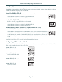
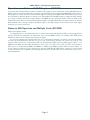
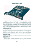
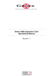
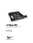
AES8+ I/O Card Operating Information v 1.0
AMBus AES 8+ I/O Card
Installing the AMBus Card
To install the AMBus card into your AD-8000, Trak2 or other AMBus-equipped system, first make sure the
power is turned off. You may wish to keep the unit plugged into a grounded AC receptacle so as to minimize
the chance of static discharge, and avoid standing on carpeting while carrying out this procedure. Keep the new
AMBus card in its packaging until you are ready to install. Now turn the unit around so you’re facing the back
panel. Remove the plate covering an available AMBus slot. Ground yourself by touching a connector on the rear
panel and unpack the card. Insert the card until you feel it mate with the connector at the back of the card bay.
Fasten the card in place with the captive screws provided on the card panel.
AES with the AD-8000 and Trak2
The AES8+ I/O card provides eight channels of AES/EBU-compatible signals in and out, in addition to the
eight channels of AES out and two channels of AES in on the main AD-8000 back-panel, or the two channels of
AES out on the Trak2 rear panel. The AES8+ card provides a full eight channels of AES/EBU in. For use with
recorders such as the Sony PCM-800 or other multi-channel recorders with AES interfacing, the card includes
“bit-splitting” formats which split high resolution signals among multiple 16-bit tracks, at the cost of having
fewer total tracks available for recording. The AES8+ card additionally provides both “double-wire” and “single-wire” operation at high sample rates (88.2 and 96 kHz). High sample rates are only supported in units
(such as the Trak2) that can handle high sample rates. On the AD-8000, the high sample rate modes are
not available.
AES8+ Card I/O Formats
The AES8+ card supports the following digital audio formats:
1. Single-Wire 24-bit AES x 8: 8 channels of up to 24 bits at up to 96 kHz sample rate
2. Double-Wire 24-bit AES x 4: 4 channels of 24-bit Double-Wire AES I/O at 88.2/96 kHz sampling
3. ABS 4/24: 4 channels of 24 bits each (Rane’s PaqRat format) bit-split on to an 8-track 16-bit recorder at 44.1
or 48 kHz sampling
4. ABS 96: 2 channels of 24-bit, 88.2/96 kHz audio bit-split on to an 8-track 16-bit recorder at 44.1 or 48 kHz
sampling
Note that there are two ABS formats. The first mode (“4/24”) allows four 24-bit channels to be recorded and
replayed across eight 16-bit tracks, while the second (“ABS96”) allows two channels of 24/96 audio to be
recorded and replayed on a conventional 16-bit, 44.1/48 kHz MDM or other recording device.
4/24 mode is compatible with Rane’s PaqRat system, and thus permits replay of tracks previously recorded
with an Apogee AD-1000 Platinum Edition, PSX-100 or Rosetta system. In this mode, each 24-bit channel is
recorded on two adjacent 16-bit tracks. The 16 most-significant bits of the first 24-bit channel are recorded on
the first track of the pair, while the remaining eight bits are recorded on the second track. The final eight bits
of the second track carry a tone to indicate that this track was not designed to be monitored on its own (as a
result, even numbered tracks always have signal present on record). The odd-numbered tracks, however, may
be monitored if desired (bearing in mind that they will only deliver 16-bits of resolution). NOTE: As this is a 24bit mode: when using this mode, ensure that UV22HR is turned off on the channels you are using.
An advantage of the 4/24 mode is that you can record or overdub on an individual 24-bit channel, by
recording on two adjacent odd/even tracks at the same time, without damaging any other tracks.
ABS 96 mode uses eight 44.1/48 kHz, 16-bit channels (such as tracks on a conventional modular digital multitrack) to record or replay two channels of full 24-bit, high resolution 88.2 or 96 kHz sample rate audio. NOTE:
As this is a 24-bit mode: when using this mode, ensure that UV22HR is turned off on the channels you are
using.
The bit-splitting modes are selected by DIP switches on the back of the AES8 card, as shown below. Note
that on the card switches, UP is OFF and DOWN is ON. This is the opposite of the switches on the rear of
the AD-8000.
Page 1
AES8+ I/O Card Operating Information v 1.0
Configuring DIP switches 1 & 2
DIP switches 1 & 2 are used to configure the 8 channels of AES I/O to the desired format. Please note that
when 96kHz is indicated, both 88.2 and 96kHz sampling rates are available; likewise, when 48kHz is indicated,
both 44.1 and 48kHz sampling rates are available.
Single-Wire 24-Bit AES x 8
Set DIP 1 & 2 ON, or down; AES I/O is now formatted as follows:
•
•
at 88.2/96kHz = 8 channels of 24-bit Single-Wire AES I/O
at 44.1/48kHz = 8 channels of 24-bit AES I/O
Double-Wire 24-Bit AES x 4
Set DIP 1 & 2 OFF, or up; AES I/O is now formatted:
•
•
at 88.2/96kHz = 4 channels of 24-bit Double-Wire AES I/O
at 44.1/48kHz = 8 channels of 24-bit AES/EBU I/O
ABS Bit-splitting (ABS96 at 88.2/96; PaqRat 4/24 at 44.1/48)
Set DIP 1 OFF, DIP 2 ON; AES I/O is now formatted:
•
•
at 88.2/96kHz = two channels of 88.2/96kHz 24-bit audio are transferred via 8 channels
of 44.1/48kHz 16-bit AES, for use with a multitrack 44.1/48kHz 16-bit device. (“ABS96”)
at 44.1/48kHz = 4 channels of 24-bit AES/EBU I/O are transferred via 8 channels of
44.1/48 kHz AES, for use with a multitrack 44.1/48kHz 16-bit device. (PaqRat 4/24
mode)
Note: DIP 1 ON, DIP 2 OFF is not valid and will give undefined results.
Configuring DIP switches 3 & 4
DIP switches 3 & 4 select the AES input pair to be used as a sync source, if the unit in which the AMBus
AES8+ card is installed is set to lock to that card.
Sync to AES In 1 & 2
• Set DIPs 3 & 4 ON
Sync to AES In 3 & 4
• Set DIP 3 OFF, DIP 4 ON
Sync to AES In 5 & 6
• Set DIP 3 ON, DIP 4 OFF
Sync to AES In 7 & 8
• Set DIP 3 & 4 OFF
Page 2
AES8+ I/O Card Operating Information v 1.0
Interconnection
The AES 8+ card provides eight channels of I/O on a single female 25-pin D-sub connector. This connector
is wired to the same pinout as used by Yamaha for interfacing their AES digital devices. The pinout is as follows:
1 In Hot 1/2
5 Out Hot 1/2
14 In Cold 1/2 18 Out Cold 1/2
2 In Hot 3/4
6 Out Hot 3/4
15 In Cold 3/4 19 Out Cold 3/4
3 In Hot 5/6
7 Out Hot 5/6
16 In Cold 5/6 20 Out Cold 5/6
4 In Hot 7/8
8 Out Hot 7/8
17 In Cold 7/8 21 Out Cold 7/8
Pins 10, 12, 13, 22, 24 and 25 are connected to ground.
Pins 9, 11 and 23 are not used.
Channel routing LED matrix (AD-8000 only)
Bit Splitting Modes
Bit-splitting is indicated on the channel routing matrix. If 4-channel/24-bit (4/24) bit-splitting is enabled on
one or two installed AMBus cards, then channels 1/2 and 3/4 light in the A or C row and channels 5/6 and 7/8
in the B and D row, depending on the position of the card(s).
If 6-channel/20-bit (6/20) bit-splitting is enabled on an installed AMBus card, then the channel LEDs 1-6 for
that row are turned on, indicating that channels 1-6 are selected for input.
Source and Destination Monitor Modes
When an AMBus card is in source monitor mode, and it is selected as the digital source, its outputs will be
muted (DEST LEDs will be OFF for that card) to prevent the possibility of digital feedback or looping.
If the unit is in “tape monitor” (destination) mode, and you are monitoring a selected AMBus card, only one
of the DEST LEDs is illuminated – the one for the selected AMBus card. Remember that ABS is a two-way, realtime process: you can monitor a 24-bit ABS signal in destination mode while you are recording it (see below).
Recording and Playback with the AES8 Card
General Operation
Having installed the card, select the mode you wish to use according to the DIP switch settings described
above. We will describe the procedure for simple (non-ABS) operation, using the AD-8000 as the timing reference. Operation with the Trak2 is analogous.
The only differences when operating in an ABS mode are the settings of the card switches and the synchronization of multiple machines, if they are used, and these are covered in the following section. To synchronize
the AD-8000 or Trak2 to a different timing source, see the manual. It is recommended to adjust DIP switch settings with the power off to ensure that settings changes are registered. Use a cable with the pinout shown
above to link the card to the AES device.
Normally the AD-8000 will be utilized as the sync source when the system is being used as an A/D conversion system, in which case set the SYNC SOURCE to CRYSTAL. Alternatively, you can synchronize the AD-8000
to other sources such as video (if the video sync module is installed) or a digital input. See your AD-8000 manual for details. You can synchronize the AD-8000 to any adjacent odd/even pair of AES input channels coming
into the AES8 card by setting DIP switches 3 and 4 accordingly and setting the SYNC SOURCE on the AD-8000
to look at the card slot into which the AES8 card is installed.
To operate in normal (single-wire, non-bit-splitting) mode, ensure that DIP switches 1 and 2 on the card
are set to ON. All on-board and card-based digital outputs on the AD-8000 are available at all times, enabling
recording or transmission on more than one format simultaneously.
To return digital signals into the unit, ensure that the AES device and the AD-8000 are connected as
described above, and choose your synchronization source as discussed. Press the AD-8000 “DIGITAL IN” button and select the channel pairs you wish to enable for digital input, or simply hold the “DIGITAL IN” button to
illuminate all eight digital input indicators and set all the channels to digital input.
In the Digital Routing section of the AD-8000 front panel (upper far right of the unit), press the “SOURCE”
button until the correct AMBus card is selected. Refer to the earlier section on the routing matrix to check the
LED display indications are correct.
You are now ready to receive digital signals from your AES device.
Page 3
AMBus AES 8+ Card Operating Information
Operation as an 8-channel A/D-D/A system (AD-8000)
If you have the 8-channel D/A converter installed in the system, you can effectively use the AD-8000 with the
AES8+ card as an 8-channel A/D with a separate 8-channel D/A. Press and hold the MONITOR button (next to
the headphone socket) down until a letter (A through D) is displayed. The DEST LED will illuminate and you will
be in Destination Monitor Mode. If necessary, use the headphone VOLUME switch to nudge the letter display
up or down to display the letter corresponding to the AMBus slot into which the AES8+ card is installed. In this
mode, AES inputs fed to the card will be directed straight to the D/A. Meanwhile, the input channels of the AD8000, whether set to analog or digital, will deliver signal to the AES outputs on the card (and the other digital
interfaces for format conversion).
Notes on ABS Operation and Multiple Cards (AD-8000)
While in bit splitting mode:
If a digital input pair is assigned which does not exist, the corresponding DIG x/x LEDs on the assigned channel pair will flash. For example, if in 4/24 mode, and a second AMBus card is not installed, LEDs DIG5/6 and
DIG7/8 will flash if those channels are assigned as digital.
If a card set to 4/24 mode is installed in slot A or C, it will pick up channels 1–4, and ch 1–4 on the dot matrix
for that row are illuminated. If the card is in slot B or D, it will pick up channels 5–8, and ch 5-8 are lit up. The
selection LED for that slot is illuminated. With two bit-splitting-capable cards installed (eg two AES's, or an
ADAT8 and an AES), the dot matrix illuminates 1-4 for slot A or C, and 5-8 for slot B or D. Two of the selection
LEDs are on, corresponding to AMB A and AMB B, or AMB C and AMB D, and the 24 bit resolution LED is on.
If one of the two cards has a slip or format error, then the “DIGITAL IN” LED flashes. If there is no second card
or the second card is not capable of bit splitting, then operation is identical to the one card case (only 1-4 or 58 are illuminated).
Page 4