1
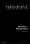
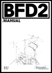
User Manual
Nord Drum
Part No. 50369
Print Edition 1.1
Copyright Clavia DMI AB 2012
The lightning flash with the arrowhead symbol within
an equilateral triangle is intended to alert the user to the
presence of uninsulated voltage within the products enclosure that may be of sufficient magnitude to constitute
a risk of electric shock to persons.
CAUTION - ATTENTION
RISK OF ELECTRIC SHOCK
DO NOT OPEN
RISQUE DE SHOCK ELECTRIQUE
NE PAS OUVRIR
Le symbole éclair avec le point de flèche à l´intérieur d´un triangle
équilatéral est utilisé pour alerter l´utilisateur de la presence à
l´intérieur du coffret de ”voltage dangereux” non isolé d´ampleur
suffisante pour constituer un risque d`éléctrocution.
CAUTION: TO REDUCE THE RISK OF ELECTRIC SHOCK
DO NOT REMOVE COVER (OR BACK).
NO USER SERVICEABLE PARTS INSIDE.
REFER SERVICING TO QUALIFIED PERSONNEL.
The exclamation mark within an equilateral triangle is
intended to alert the user to the presence of important
operating and maintenance (servicing) instructions in the
literature accompanying the product.
ATTENTION:POUR EVITER LES RISQUES DE CHOC ELECTRIQUE, NE
PAS ENLEVER LE COUVERCLE.
AUCUN ENTRETIEN DE PIECES INTERIEURES PAR L´USAGER.
CONFIER L´ENTRETIEN AU PERSONNEL QUALIFE.
AVIS: POUR EVITER LES RISQUES D´INCIDENTE OU D´ELECTROCUTION,
N´EXPOSEZ PAS CET ARTICLE A LA PLUIE OU L´HUMIDITET.
Le point d´exclamation à l´intérieur d´un triangle équilatéral est
employé pour alerter l´utilisateur de la présence d´instructions
importantes pour le fonctionnement et l´entretien (service) dans le
livret d´instructions accompagnant l´appareil.
Instructions pertaining to a risk of fire, electric shock or injury to persons.
IMPORTANT SAFETY INSTRUCTIONS
SAVE THESE INSTRUCTIONS
Warning - When using electric products, basic precautions should always be followed, including the following:
1) Read these instructions.
10) Protect the power cord from being walked on or pinched
particularly at plugs, convenience receptacles, and the point
2) Keep these instructions.
where they exit from the apparatus.
3) Heed all warnings.
11) Only use attachments/accessories specified by the manufacturer.
4) Follow all instructions.
5) Do not use this apparatus near water.
6) Clean only with dry cloth.
7) Do not block any ventilation openings. Install in accordance
with the manufacturer’s instructions.
8) Do not install near any heat sources such as radiators, heat
registers, stoves, or other apparatus (including amplifiers) that
produce heat.
12) Use only with the cart, stand,
tripod, bracket, or table specified by the
manufacturer, or sold with the apparatus.
When a cart is used, use caution when
moving the cart/apparatus combination to
avoid injury from tip-over.
13) Unplug this apparatus during lightning
storms or when unused for long periods of time.
9) Do not defeat the safety purpose of the polarized or
grounding-type plug. A polarized plug has two blades with one
wider than the other. A grounding type plug has two blades
and a third grounding prong. The wide blade or the third prong
are provided for your safety. If the provided plug does not fit
into your outlet, consult an electrician for replacement of the
obsolete outlet.
14) Refer all servicing to qualified service personnel. Servicing
is required when the apparatus has been damaged in any way,
such as power-supply cord or plug is damaged, liquid has been
spilled or objects have fallen into the apparatus, the apparatus
has been exposed to rain or moisture, does not operate normally, or has been dropped.
No naked flame sources, such as lighted candles, should be placed on
the apparatus;
Il convient de ne pas placer sur l´appareil de sources de flammes nues,
telles que des bougies allumées;
Do not use the apparatus in tropical climates.
L´appareil n’est pas destiné á étre utilisé sous un climat tropical.
Additional Safety Information
WARNING: To reduce the risk of fire or electric shock, do not expose
this apparatus to rain or moisture.
The apparatus shall not be exposed to dripping or splashing and that
no objects filled with liquids, such as vases, shall be placed on the
apparatus.
L´appareil ne doit pas étre exposé á des égouttements d´eau ou des
éclaboussures et de plus qu´aucun objet rempli de liquide tel que des
vases ne doit étre placé sur l´appareil.
The maims plug is used as the disconnect device and shall remain
readily operable.
Lorsque la prise du résau d’alimentation est utilisée comme dispositif
de déconnexion, ce dispositif doit demeuré aisément accessible.
Trademarks: The Nord logo is trademark of Clavia DMI AB. All other trademarks mentioned
in this publication are the properties of their respective holders.
Specifications and appearances are subject to change without notice.
Copyright © Clavia DMI AB
Nord Drum User Manual
1 Stand holder & connections
Attaching the stand holder . . . .
Connections . . . . . . . . . . . . . . . . . . . .
4
4
MIDI In, MIDI Out . . . . . . . . . . . . . . . . . . 4
Trig Inputs CH1 - CH4 . . . . . . . . . . . . . . 5
Power . . . . . . . . . . . . . . . . . . . . . . . . . . . 5
2 Getting Started
Connecting pads . . . . . . . . . . . . . . .
Adjust Input Sensitivity . . . . . . . .
Threshold . . . . . . . . . . . . . . . . . . . . . .
Play the Demo . . . . . . . . . . . . . . . . .
MIDI Channel Learn . . . . . . . . . . . .
MIDI Note Learn . . . . . . . . . . . . . . .
Four Modes . . . . . . . . . . . . . . . . . . . .
Basic editing . . . . . . . . . . . . . . . . . . .
The Red parameters . . . . . . . . . . . . . . .
Solo Edit . . . . . . . . . . . . . . . . . . . . . . . . .
Memory Protect . . . . . . . . . . . . . . . . . . .
Storing . . . . . . . . . . . . . . . . . . . . . . . . . .
3 Reference
The Panel . . . . . . . . . . . . . . . . . . . . .
10
Program Store button . . . . . . . . . . . . . 10
Input Trig Level LEDs . . . . . . . . . . . . . .10
Channel Select button . . . . . . . . . . . . 10
Sound Init . . . . . . . . . . . . . . . . . . . . . . 11
Shit/Exit button . . . . . . . . . . . . . . . . . . 11
Dial . . . . . . . . . . . . . . . . . . . . . . . . . . . 11
Trig button . . . . . . . . . . . . . . . . . . . . . . 11
Parameter buttons . . . . . . . . . . . . . . . 11
Noise Parameters . . . . . . . . . . . . . . . . 11
6
Color . . . . . . . . . . . . . . . . . . . . . . . . . . . . . . .
Filter/Type . . . . . . . . . . . . . . . . . . . . . . . . . . .
Sweep/Time . . . . . . . . . . . . . . . . . . . . . . . . .
Decay/Gate . . . . . . . . . . . . . . . . . . . . . . . . . .
6
Mixer Parameters . . . . . . . . . . . . . . . . 12
6
7
7
7
7
8
8
8
9
9
11
11
11
12
Tone, Noise, Click level . . . . . . . . . . . . . . . . . 12
Channel level . . . . . . . . . . . . . . . . . . . . . . . . . 12
Tone Parameters . . . . . . . . . . . . . . . . 12
Wave . . . . . . . . . . . . . . . . . . . . . . . . . . . . . .
Filter/Punch . . . . . . . . . . . . . . . . . . . . . . . . .
Sweep/Time . . . . . . . . . . . . . . . . . . . . . . . . .
Decay/Gate . . . . . . . . . . . . . . . . . . . . . . . . .
Pitch . . . . . . . . . . . . . . . . . . . . . . . . . . . . . . .
Bend Range/Bend Time . . . . . . . . . . . . . . .
12
12
12
13
13
13
Click Parameters . . . . . . . . . . . . . . . . . 13
Type . . . . . . . . . . . . . . . . . . . . . . . . . . . . . . . . 13
Decay/Gate . . . . . . . . . . . . . . . . . . . . . . . . . . 13
Shift Parameters . . . . . . . . . . . . . . . . . 13
Copy . . . . . . . . . . . . . . . . . . . . . . . . . . . . . . . . 13
Paste . . . . . . . . . . . . . . . . . . . . . . . . . . . . . . . 14
Prog Dump . . . . . . . . . . . . . . . . . . . . . . . . . . . 14
MIDI Ch . . . . . . . . . . . . . . . . . . . . . . . . . . . . . 14
MIDI Note . . . . . . . . . . . . . . . . . . . . . . . . . . . . 14
Trig Type . . . . . . . . . . . . . . . . . . . . . . . . . . . . . 14
Inp Thres . . . . . . . . . . . . . . . . . . . . . . . . . . . . 15
Inp Sens . . . . . . . . . . . . . . . . . . . . . . . . . . . . . 15
MIDI Operation . . . . . . . . . . . . . . . .15
Storing the memory content . . . . . . . . 15
Receive MIDI Dumps . . . . . . . . . . . . . . 16
Updating the Operating System . . . . . . 16
Appendix
Factory Soundbank . . . . . . . . . . . . . . . 17
4 | Nord Drum User Manual OS v1.x
1
Stand holder & connections
Attaching the stand
holder
The stand holder makes it possible to mount the
Nord Drum on a stand that is equipped with a
clamp. The stand holder with its diameter of 23
millimeter is designed to fit with most general
purpose clamps.
Connections
POWER
CH 4
CH 3
CH 2
CH 1
AUDIO OUT
Audio Out
The Audio output is a line level, mono signal on a
¼" jack. EE Always turn on the Nord Drum first and the
sound system last, and the reverse order
when you wish to turn it off again.
EE The Nord Drum is capable of producing
sounds with a very wide and rapidly changing
dynamics and frequency ranges. Be careful
when you use the unit and when you edit the
sounds. Keep the level at moderate settings,
in order not to overload a connected sound
system by making drastic changes with the
available parameters.
MIDI In
Connect the MIDI Input to a drum pad or sequencer if you want to control the sounds in the
Nord Drum via MIDI. The MIDI Input is also used
to update the unit with new operating systems.
MIDI Out
Connect the MIDI Output to a computer or
sequencer if you want to use the Program Dump
feature to transfer the settings to the sounds in
the Nord Drum via MIDI. A performance on pads
connected to the Trig Inputs will also be transmitted as MIDI notes.
Chapter 1 Stand holder & connections Trig Inputs CH 1 – CH 4
Connect a suitable signal source to the Trig
Input ¼” jacks. These inputs can be used with
a variety of different signals. The sensitivity and
the threshold of the inputs can be adjusted by
using the Inp Sens and Inp Thres parameters,
read more about this in the following chapter.
The Nord Drum has been tested with many
different pads during the development. The
Trig Inputs are designed to be very versatile
and to accept many different kinds of signals. They are able to provide you with a very fast
and dynamic response. If you experience double triggered sounds,
flams or a slow response from the Nord Drum,
make sure that you adjust the Trig Type, Inp
Thres and Inp Sens parameters. Read more
on how to adjust these settings this on page 6
and page 14.
Power
Connect the Nord Drum power supply to the
Power input. If the original supply is not available, use only a 12 volt DC, 250 mA adapter,
with a barrel type plug that has the positive
current on the tip. The outer diameter of the
plug is 5.5 millimeter and the inner diameter is
2.1 millimeter.
| 5
4
6 | Nord Drum User Manual OS v1.x
2
Getting Started
3 Press the Channel Select button to move
Connecting pads
1 Connect a pad to one of the four Trig Inputs
on the Nord Drum. The Trig Inputs can be
used with mono or stereo connections. the solid green LED to the channel that the
pad is connected to. This is called to move
the Edit focus, you set the unit to be ready
to change the settings on that particular
channel. 4 Hold Shift and press the Inp Sens button on
the Nord Drum panel. The red LED above
the button will start to blink to indicate that
the parameter printed below the second row
is active for editing.
POWER
CH 4
CH 3
CH 2
CH 1
AUDIO OUT
In general, the factory sounds use Channel 1
for Bass drum sounds, channel 2 for Snare,
channel 3 for Hi tom and channel 4 for Lo
Tom.
Adjust Input sensitivity
1 Strike the pad, listen to the sound from the
Nord Drum and look at the Input Trig Level
LEDs for that particular channel. The LEDs
indicate the strength of the incoming trigger
signal. 2 The red LED should be lit a bit longer when
you hit the pad with your strongest force. 5 Strike the pad and adjust the Input sensitivity by turning the Dial to match the pad
response and your striking force. Threshold
If you have several pads or other pieces in your kit
that are mounted on the same hardware, use the
Inp Thres parameter to eliminate any unwanted,
accidental triggers from other units.
1 Select the Channel that is receiving the
unwanted triggers. 2 Hold Shift and press the Inp Thres button.
Chapter 2 Getting Started | 7
6
3 Transmit a MIDI note or other message from
the MIDI controller. The incoming channel will
be displayed in the LED. MM The Nord Drum can only receive on one MIDI
channel at a time.
3 Strike the pad or drum that causes the unwanted triggers and raise the Inp Thres value
with the dial until the Nord Drum channel
stops triggering.
4 Strike the pad that should trigger the Nord
Drum to verify that the new Inp Thres setting
has not changed the desired response. MIDI Note Learn
1 Connect a MIDI pad or other MIDI controller
to the MIDI Input on the Nord Drum. 2 Press the Channel Select button on the Nord
Drum to select one of the channels. Play the Demo
1 Press the Program, Channel Select and Trig
buttons simultaneously to start the Demo
playback. 2 Turn the Dial while the demo is playing to
listen to the various sounds in the Factory
soundbank. 3 Press Shift/Exit to stop the playback.
3 Hold Shift and press the MIDI Note button. Turn the dial until you reach the setting after
127, “L r n”. 4 Strike the pad on the MIDI unit that you
wish to assign to the selected Nord Drum
channel. The note number that the MIDI pad transmitted will be assigned to this Nord Drum channel and will be shown in the display.
5 Repeat steps 2, 3 and 4 to assign the other
MIDI Channel Learn
If you wish to control the Nord Drum with a MIDI
controller, the MIDI channel and the notes that this
controller transmits can be automatically assigned
by the Nord Drum to trigger the four channels.
1 Connect a MIDI pad or other MIDI controller
to the MIDI Input on the Nord Drum. 2 Press Shift and the MIDI Ch button and scroll
with the Dial until you reach “L r n”. MM The LED above the MIDI Ch button will flash
to indicate that your are editing System
parameters.
three channels to the additional MIDI note
numbers that the MIDI unit transmits. 6 Press the Program button to Exit the System
edit mode.
Four Modes
When the display shows the letter P followed by
a number, this is the Program Mode. Turn the Dial
to select any of the 99 programs. When one of the red LEDs in the two rows below
the LED is lit and the display shows shows one or
two set s of numbers, this is the Edit Mode where
you can change the settings of the selected
parameter with the Dial. 8 | Nord Drum User Manual OS v1.x
The Solo Edit Mode is active if you hold Shift and
press the Row Select/Solo Edit button. Only the
component that is currently being edited will be
heard when you trigger the channel.
3 A parameter is selected by simply pressing a
button. This will activate Edit Mode and the
display will show parameter values. When one of the lower row LEDs are flashing, this
mean that the System Mode is active where the
parameter printed below the second row button is
adjustable with the Dial.
Basic editing
The Nord Drum has 4 channels, it can produce 4
simultaneous sounds. Each one of the channels
has a complete and identical set of parameters. 4 To change the row to the lower set of param-
A sound in the Nord Drum is made with a blend
of up to three components: Noise, Tone and
Click. Each one of these components has their
individual set of parameters.
5 Turn the Dial to change the setting of a
Channel
Trig
Input
Tone
Noise
Output
Mixer
Level
Click
eters, double-tap on a parameter button or
use the Row Select button to the left.
parameter. 6 Press the Channel Select button repeatedly
to select which one of the four channels to
edit.
The Red parameters
Eight of the buttons have additional parameters
assigned to them, indicated with red text. These
are displayed with dual values in the display with
the red parameter to the left.
1 The additional left value is changed by hold1 Use the Trig button in the lower right corner
to play the sound on one channel at a time. Triggering sounds from the panel are made
with a fixed velocity.
If you have pads connected, these can be
used as well and will make the sounds respond to the velocity of your playing.
2 Press the Channel Select button repeatedly
to select one of the four channels. The channel parameters are accessed with the
grid of two rows with eight buttons. ing down the parameter button and then
turning the Dial.
Solo Edit
The Solo Edit feature can be used to playback
only the Noise, Tone or Click components when
you select the parameters for these. This allows
you to edit the parameters and only hear the
particular component you are working with in
isolation.
Chapter 2 Getting Started 1 Hold Shift and press the Row Select/Solo
Edit to activate the Solo Edit mode. 2 Strike a pad or use the Trig button to hear
only the component that is currently being
edited. If the Channel Level parameter is selected, all
components will be heard.
Storing
When a Program has been changed, this is
indicated with a dot to the right of the program
number. If you select
another program,
your edits will
be lost. If you
want to keep any
changes you have made, you have to Store the
edited program. 1 Hold Shift and press the Program/Store
button.
2 The display will start to blink. 3 Press the Program button to exit the Solo
and Edit mode. The LED will show a P followed by a program number.
Memory Protect
When the Nord Drum is shipped from the factory,
storing programs to the memory is not possible
until you turn off the Memory protection. This is
done with one of the System parameters. MM If the Memory Protect is On, the display will
show “P r t” when you try to Store a Program
1 Hold Shift and press repeatedly on the Prog
Dump button until “P On” is shown in the
display.
2 Turn the Dial to the “P Of” setting. This will allow you to store programs until this
parameter is set to On again.
3 Exit the System mode by pressing the Program button. 3 Press Program/Store again without turning
the Dial to store the edited program to the
current location. Storing to a new location
1 Hold Shift and press the Program/Store button. The display will start to blink.
2 Use the Dial to pick a location for the new
Program. 3 Confirm your intentions by pressing Store a
second time. This method can also be used to make copies of a Program.
| 9
8
10 | Nord Drum User Manual OS v1.x
3
Reference
The Panel
Master Level
The Master Level controls the
overall output level of the Nord
Drum. This is not a programmable control.
Program/Store button
Press the Program button to exit any other mode
and to enter the Program mode. The LED display
will show a P followed by a number. There are 99
programs in the Nord Drum. MM If a program has
been edited but
not yet stored, this
will be indicated
by a dot in the
lower right corner
of the LED.
Storing a program
Storing a Program is described on page 9. Program/Value LED display
Program mode is indicated with a P, followed by
a number between 1 and 99. Edit mode is when a
parameter in the Nord
Drum is selected. The
presentation of the settings will be made with
numbers and/or symbols. Some parameters have
dual settings, one indicated to the right and the
other to the left in the display. When you want to change one of the red
parameters, hold down
the parameter button
and turn the dial. Solo Edit mode is activated by holding Shift
and pressing the Row Select/Solo Edit button. The Solo Edit LED will blink and only the component that is being edited will be heard.
System mode is when the System parameters
are selected by holding Shift and pressing a
parameter button.
Input Trig Level LEDs
The Input LEDs will flash to
indicate the activity in the
four channels. A solid green
LED indicates that a channel
is selected for editing.
The upper LEDs are red and will flash briefly when
a trigger input receives a strong signal. It will be lit
up in a longer duration when the input receives an
optimal, as-hard-as-you-can-strike signal.
Channel Select button
Press the Channel Select button
repeatedly to select the channel to
be triggered with the Trig button on
the panel and/or to be edited with
the parameters.
You can use pads to quickly select the channel to edit, if no channel has been previously
selected with the Channel Select button. If
the button has been used to manually select
a channel, press the Program button once to
get back to the quick-select-edit-channel-bypads mode (QSECBP™).
Chapter 3 Reference Sound Init
Hold Shift and press the Channel Select button to
reset all the parameters of this channel to default
values.
Shift/Exit Button
The Shift button is used together with the buttons
to access additional parameters. These additional
parameters are identified with the text below the
buttons. The Shift button can also be used to Exit a Store
operation, if you change your mind about storing
a program. Dial
The Dial is used to select programs and to
change the setting of a selected parameter.
Trig button
Use the Trig button to trigger a selected channel
from the unit itself. Hold Shift and the Trig button
to be able to adjust the Trig button’s velocity level
with the Dial.
Parameter buttons
The parameters are accessed with the row of
eight buttons. Edit mode is activated as soon as
you press one of these buttons. If a button activates a parameter in the upper
row, a quick double-tap on the same button or by
pressing the Row Select button will move the edit
focus to the lower row parameters. Hold down a button and turn the Dial to edit a red
parameter.
| 10
11
Noise Parameters
There are several types of noise to choose from. The noise filter and sweep parameters can used
to sculpt the sound of the noise.
Color
Use the Color
parameter to change the sound of the Noise. Values below 0 will have more bass content, values
above 0 will have less.
Range: -10 - 10
Filter/Type
The Noise Filter is a Low Pass filter, it allows you
to control how much of the high frequency noise
to be filtered out of the sound. The lower you set
the value, the duller the noise will become. The second parameter is the Filter Type. There are
7 different types, each with an increasing amount
of resonance that gives the filter a different sound
quality. The Type setting is changed by holding
the button, while turning the dial.
Filter Range: 0 - 99. Range Type: 1 - 7
Sweep/Time
The Sweep/Time parameters opens up the noise
filter a bit with an envelope when you trigger the
sound. The Sweep parameter sets how much
the filter should be opened up and it is velocity
sensitive. The Time parameter sets the duration of the
envelope. The Time setting is proportional to the
Decay (see below) and is changed by holding
the button, while turning the dial. A setting of 9
makes this envelope have the same duration as
the Decay.
Range Sweep: 0 - 10. Range Time: 0 - 9
12 | Nord Drum User Manual OS v1.x
Tone Parameters
Decay/Gate
The Decay parameter allows you to set the length
of the Noise. A higher value means a longer noise. The Gate parameter controls if the noise should
gradually decay (the “n” setting), have a “soft
knee” characteristic (“S”) or decay very rapidly
(“G”). The Gate parameter is changed by holding
the button, while turning the dial.
Range Decay: 0 - 50. Range Gate: n, S, G
Trig Gate n
Trig Gate S
Trig Gate G
Mixer Parameters
Use the Mixer parameters to mix the separate
noise, click and tone levels. The channel level sets
the overall output
of the sound.
Tone, Noise, Click
These parameter set the level of the individual
Tone components in the channel. Ranges: 0 - 10
Channel Level
This sets the overall loudness of the selected
channel.
Range: 0 - 99
The Tone component can be described as the
body of the sound. Start by selecting a waveform
and then use the other parameters to get the tone
as you want it.
Wave
There are several different waveforms in the Nord
Drum, each with its own characteristic. Some
have distinctive pitches, others are of a more
metallic variety. “An” are analog waves, “b” have
a drum-like personality and the “c” waves are
“percussive”.
Range: An 1-3, b 1-9, c 1-5
Filter/Punch
The filter is a lowpass filter that can make the
Tone duller. A setting of 99 is a fully opened filter,
0 is a closed filter. Punch adds an short, velocity controlled attack
portion to the waveform.
Range Filter: 0 - 99. Range Punch: 0 - 9
Sweep/Time
The Sweep/Time parameters open up the Tone
filter a bit with an envelope when you trigger the
sound. The Sweep parameter sets how much
the filter should be opened up and it is velocity
sensitive.
The Time parameter sets the duration of the
envelope. The Time setting is proportional to the
Decay (see below) and is changed by holding
the button, while turning the dial. A setting of 9
makes this envelope have the same duration as
the Decay.
Range Sweep: 0 - 10. Range Time: 0 - 9
Chapter 3 Reference Decay/Gate
The Decay sets the length of the Tone. The higher
the value, the longer the sound. The Gate parameter controls if the tone should
gradually decay (the “n” setting), have a “soft
knee” characteristic (“S”) or decay very rapidly
(“G”). See the illustration on page 12. The Gate
parameter is changed by holding the button, while
turning the dial.
Range Decay: 0 - 50. Range Gate: n, S, G
Pitch
Use the pitch control to set the pitch of the Tone. The pitch is set in half steps of semitones and
shown in the LED as MIDI Note Numbers. A setting of 69.0 equals A = 440 hz. Range: 11.0 - 98.5
Bend Range/Bend Time
The Bend parameter bends the pitch of the Tone. The Bend has two directions – a negative value
bends up, a positive values bends down. The
amount of Bend is set with the first parameter,
this is feature is also velocity sensitive. The Bend Time parameter sets the duration of the
bend. The Time setting is proportional to the Tone
Decay and is changed by holding the button,
while turning the dial. A setting of 9 makes this
envelope have the same duration as the Decay.
Range Bend: -9 / 30. Bend Time: 0 - 9
Click Parameters
The Click is a sharp transient at the very
beginning of a sound. Type
There are several different
Click types in the Nord Drum,
each with a different characteristic. The n-clicks
are noise waveforms with different characters,
the c-clicks are still made from noise but with an
| 13
12
added attack. The t-clicks are more of a pitched
variety.
Range: n1 - n9, c1 - c9, t1 - t9
Decay/Gate
The Decay sets the length of the Click. The higher
the value, the longer the sound. The Gate parameter controls if the noise should
gradually decay (the “n” setting), have a “soft
knee” characteristic (“S”) or decay very rapidly
(“G”). See the illustration on page 12. The Gate
parameter is changed by holding the button, while
turning the dial.
Range Decay: 0 - 20. Range Gate: n, S, G
Shift Parameters
The second row has an additional set of parameters that are accessed by holding the Shift button
while pressing the corresponding button. The first two of these parameters are immediate
actions (Copy and Paste), the rest are Global settings and features. The System settings will remain in the unit
after it has been turned off with one exception.
Local will always revert to On when the unit is
turned on..
Copy
This function allows you to copy all the settings
of the selected channel. The copy can be pasted
to another channel in the same program or to a
channel in another program of your choice by
using Paste. The copied settings will remain in a
memory buffer until you perform another copy or
turn the unit off. 14 | Nord Drum User Manual OS v1.x
Paste
After you have copied a channel, and selected
another program and/or channel as a destination,
use this function to paste the settings. The same
copied settings can be pasted to several destinations, one at a time if you wish.
Prog Dump
The Prog Dump button has three functions,
Memory Protect, Dump One and Dump All. These
are accessed by repeatedly pressing the Prog
Dump button.
Memory Protect is set to On when the Nord
Drum leaves to factory to protect the programs in
the memory from being accidentally overwritten. Dump One allows you to dump the current program from the Nord Drum as MIDI Sys Ex data. Use this to create safety copies of your individual
programs or to share them with other Nord Drum
users. The transmission is activated by pressing
the Program button when “ONE” is shown in the
display. Dump All transmits all the 99 programs in the
Nord Drum memory as MIDI Sys Ex data. The
transmission is activated by pressing the Program
button when “ALL” is shown in the display.
The transmission and receiving operations are described in the MIDI Operation chapter on page 15. MIDI Ch
The MIDI Ch button has three functions. MIDI
Channel, Local On/Off and Program Change Receive On/Off. These are accessed by repeatedly
pressing the MIDI Ch button.
MIDI Channel: Set the Nord Drum to receive
MIDI on a MIDI channel of your choice. The last
entry is the Learn feature, when incoming MIDI
data will determine which MIDI channel the Nord
Drum should respond to.
Range: 1 -16, Off, L r n
Local On/Off is indicated as L On or L Of. Use
Local Off if you use the Nord Drum in a situation
where a sequencer is echoing back notes and
data. Range: L On, L Of
Program Change can be set to Off, Send only,
Receive only and both Send and Receive. Set this
to receive if you want to change the programs on
the Nord Drum from a MIDI controller
Range: P Of, P S, P r, P Sr
MIDI Note
Each of the four channels can be manually assigned to respond to an incoming MIDI note.
MIDI Learn Mode is the last setting. When this is
selected an incoming MIDI note will be automatically set to the selected channel. The received
note number will be displayed in the LED.
Range: 0 - 127, L r n
Trig Type
The Trig Type buttons provide access to 2 parameters, Trig Type and Dyn Response Curve. These
are accessed by repeatedly pressing the Trig Type
button. T
Trig Type: The different Trig Types that allows you
to match the response of the Nord Drum to the
output from your pad or drum trigger. The trigger output from different types of pads
and manufacturers varies a lot. The setting of the
Trig Type parameter should be matched to suit
the output from the pads you use. The Input Trig Level LEDs provides information on
the trigger signals from the pads. The green LED
will indicate that a trigger signal is received. The
red LED will blink quickly when the trigger signal
is 6 dB below the maximum and it will be lit up
in a longer duration when the maximum signal
is fed to the Trig Input. To optimize the dynamic
Chapter 3 Reference response, make sure that only your hardest strike
lights up the red LED with the longer duration.
Here is a list of some of the pads and acoustic
triggered drums that have been used during the
development of the Nord Drum. Other pads will
work, just try the different Trig Types and settings
to determine which one is the best for your needs.
Trig Type
Pads, drums
Pd1
Roland rubber pads (PD8 etc.)
Pd2
Yamaha pads (TP65 etc.)
Pd3
Mesh pads
Ac1
Trigger fitted to kick, snare
Ac2
Trigger fitted to high, mid toms
Ac3
Trigger fitted to low toms
EE Roland and Yamaha are trademarks of their
respective owners and are not affiliated or
associated with Clavia. These trademarks are
mentioned here only as a reference to products than can be used with the Nord Drum
Range: Pd1, Pd2, Pd3, Ac1, Ac2, Ac3
Dynamics: Press the Trig Type button a second
time to select the dynamic setting. “Dn1” is a
linear response to the velocity on the pads. Try
“Dn2” if you want a “hotter” response.
Range: Dn1, Dn2
Inp Thres
Use this setting to make sure that a pad mounted
on the same hardware or other input device does
not accidentally trigger a channel. If striking a
pad that is connected to channel 2 also triggers
the sound on channel 1, raise the threshold on
channel 1.
Range: 0 - 99
Inp Sens
Use this setting to match the output signal of the
pad or input device connected to the Trig Input
of the selected channel. Adjust this to make sure
| 14
15
that only your hardest strike lights up the red LED
in its longer duration on the Input Trig Level LEDs.
Range: 0 - 99
MIDI Operation
The four channels of the Nord Drum are triggered
by incoming MIDI Notes 36, 38, 59 and 47 when
the unit is shipped from the factory. This assignment is compatible with the General
MIDI Specification for Bass drum 1, Snare drum
1, Hi tom 1 and Mid tom 1. If you prefer other
notes this can be changed in the MIDI Note setting, read more on this on page 14.
Storing the memory content
By using MIDI Sys Ex dumps, you can store all or
individual programs on a computer. The dumps
have to be recorded to a sequencer or by using
one of the many, free MIDI applications that can
receive, save and also transmit MIDI data. Windows users can do this with MIDI Ox
(www.midiox.com), Mac OSX users can use
the SysEx Librarian from Snoize Productions
(www.snoize.com).
1 Make sure that the receiver is ready to
receive and that the MIDI Out from the Nord
Drum is connected to a MIDI In on a MIDI
interface connected to the computer.
2 Press Shift and the Prog Dump button
repeatedly until ONE or ALL is shown in the
display.
One means the current program, all means
all the 99 programs in the Nord Drum.
3 Start the transmission by pressing the
Program button. After the transmission is
complete, Ok will be shown briefly in the
display.
16 | Nord Drum User Manual OS v1.x
4 Check the receiving application and make
sure that the data is there. Save the file
with a meaningful name on a nice place
on the hard drive.
MM Transmitting data will not affect the content
in the Nord Drum.
Receive MIDI Dumps
1 Make sure that your sequencer or MIDI
application is ready to transmit a Sys Ex
package and that the MIDI Out from the
MIDI interface on the computer is connected to the MIDI In on the Nord Drum. 2 Start the transmission. The Nord Drum
You will need a MIDI interface attached to the
computer in order to perform this.
1 Connect the MIDI in and the MIDI Out
from the Nord Drum to the MIDI Out and
MIDI in on the MIDI interface. 2 Double click on the OS utility to run the
Updater. MM The Windows version of the utility is a
zipped archive when you download it
from the website. This archive has to be
expanded with an application like WinRAR
before the actual utility is ready to be used.
3 Select the MIDI ports you wish to use. will automatically receive incoming MIDI
Sys Ex messages that it is compatible
with. If the Sys Ex package contains all the 99 programs, the entire memory in the Nord Drum
will be replaced by the content of the Sys Ex
package, except for any edited program that
was in the edit buffer when the transmission
started.
The Update Utility will display the current OS
version in the connected Nord Drum. If the Sys Ex package contains one program,
this program will be placed in the edit buffer
of the Nord Drum. You have to Store this program to a location in the memory, if you want
to keep it in the unit.
Updating the Operating System
The OS in the Nord Drum may be updated if
the functionality is subject to improvements.
This is achieved by using a MIDI transmission
from a computer by using an Update Utility
that can be downloaded from the .
www.norddrum.com web site. The Update
Utility is available for Windows or Mac OSX
computers, make sure you download the one
that matches your computer. 4 Click on the Update button to transfer the
new OS to the unit. Website
Please check in from time to time on the .
www.norddrum.com website for OS updates,
additional programs and other things that may
become available. Chapter 4 Appendix 4
Appendix
Factory Soundbank
There are 99 Programs locations in the Nord
Drum. The locations numbered P80 to P99 are
empty, to allow you to immediately store your own
edits without having to worry about overwriting
any programs that you might have liked. The entire memory content can be saved as a
MIDI Sys Ex file on a computer, using the methods described on page 16 in this manual. A MIDI
Sys Ex file that is a copy of the Factory Soundbank can be found on the .
www.norddrum.com website.
Style
Name
Cat.
P1
Retro
Monologue
Drums
P2
Real
Classic Vistalite Drums
P3
Retro
Blue House
Kit
P4
Real
Brushford
Kit
P5
Real
Bebop delux
Drums
P6
Retro
Always Hip Hop Kit
P7
Real
Gran Casa Timp
Drums
P8
Retro
Thanx to Burgees
Drums
P9
FX
Reso Sweep
Perc
P10
Retro
Vince Gate
Drums
P11
Retro
UnoDosKickHat
Kit
P12
Real
Spectrum
Drums
P13
Real
Ateiste Drums
P14
Retro
Noisy Barrel Orchestra
Drums
P15
Retro
Higgins Particle Hat
Kit
P16
Retro
Clothed Funk Kit
Kit
P17
Ethno
Komal Melodic
Perc
P18
Ethno
Lalalatin
Perc
P19
Retro
Bend Down Disco
Perc
P20
Retro
Flying Dront Circus
Kit
P21
Ethno
Tribunal
Perc
P22
Real
King Kong Karma
Kit
P23
FX
Training with Komal Perc
P24
Retro
Tiny Tiny Pic
Kit
P25
Ethno
Red Beat
Perc
P26
Retro
beatPerlife
Kit
P27
Retro
Piccolosim
Perc
P28
Real
Acoustic Flower King Kit
P29
FX
Apostasy Steam Noise Perc
P30
FX
DoReMinor Melodic
Perc
P31
FX
Must Bend Tolotto
Drums
P32
Ethno
Sambalasala Perc
P33
FX
Kiss the Click Perc
P34
Retro
Sweep Type 4tonight
Drums
P35
FX
Noise Click Trap
Kit
P36
Real
Bend Timpanic
Drums
P37
Retro
dododrum
Kit
P38
FX
Fast Sweep Melodic
Drums
P39
Ethno
Bella Balinese
Perc
P40
FX
Noisy Royalty Drums
P41
Ethno
Steely Melodic
Drums
P42
Real
Soft Acoustic Drums
P43
Real
Tubular Bells & Triangle
Perc
P44
Ethno
Ultra Tribal Dance
Perc
P45
Retro
HeaHihat Kit
P46
FX
Click Gate and Vinyl Kit
P47
Real
Double Snare Kit
P48
Real
Hells Bells
Perc
P49
Real
Rototsthile
Drums
P50
Retro
Melodic Technocrat Kit
P51
Real
Dull Dusty
Drums
P52
FX
Retrophile Gated Noise
Drums
| 17
18 | Nord Drum User Manual OS v1.x
P53
Ethno
Real Cuba Conga Cola
Perc
P91
P54
Retro
Retrograd
Drums
P92
P55
FX
GasaGate
Perc
P93
P56
Real
Clap Trap
Drums
P94
P57
Real
Krimsonite
Drums
P95
P58
Real
Serious Decay Kit
P96
P59
Ethno
Dry Tribe Drums
P97
P60
FX
Cinematikino Perc
P98
P61
FX
Toy Ambulance
Kit
P99
P62
Retro
Neophile
Drums
P63
Retro
Stabby Hip Hop Kit
P64
Real
Retro Noise Reverb
Drums
Styles
P65
Retro
Ulam Spiral Drums
Real: “Acoustic”. P66
Retro
Sawkas Jungle Heat
Kit
Retro: Machine or old school sounds.
P67
Retro
Knick Knock Knack Drums
P68
Real
Bright Click Brush
Drums
Ethno: World Music
P69
Retro
New Romantic Tight
Kit
FX: Weird tweaks and FX.
P70
FX
Intergalactic Battle
Perc
P71
Retro
Nosampled Drum
Drums
Categories
P72
Retro
Poor Tone
Kit
P73
FX
Clicks&Pops
Drums
Drums: Kick, Snare, Tom1 Tom2. Use these
together with acoustic hi-hat & cymbals
P74
FX
Fat Gated Chattanoga
Drums
P75
Real
RetroReal Snap Snare
Drums
P76
Ethno
Slitz Box
Perc
P77
Ethno
Real Tommy Steel
Perc
P78
FX
Macro Sweeper
Kit
P79
FX
Darwins Sex Machine
Kit
P80
Real
Apparatorium
Drums
P81
P82
P83
P84
P85
P86
P87
P88
P89
P90
Percussion: Made for 4 pads, for the standup
percussionist.
Kit: Kick, Snare, Tom, Hi-hat. Use these with a
sequencer application.
FCC Information (U.S.A.)
1. IMPORTANT NOTICE: DO NOT MODIFY THIS UNIT!
This product, when installed as indicated in the instructions contained in this manual, meets FCC requirements. Modifications
not expressly approved by Clavia may void your authority, granted by the FCC, to use the product.
2. IMPORTANT: When connecting this product to accessories and/ or another product use only high quality shielded cables.
Cable/s supplied with this product MUST be used. Follow all installation instructions. Failure to follow instructions could void
your FCC authorization to use this product in the USA.
3. Note: This equipment has been tested and found to comply with the limits for a Class B digital device, pursuant to Part 15 of
the FCC Rules. These limits are designed to provide reasonable protection against harmful interference in a residential installation. This equipment generates, uses, and can radiate radio frequency energy and, if not installed and used in accordance with
the instructions, may cause harmful interference to radio communications. However, there is no guarantee that interference will
not occur in a particular installation. If this equipment is found to be the source of interference to radio or television reception,
which can be determined by turning the equipment off and on, the user is encouraged to try to correct the interference by one or
more of the following measures:
– Reorient or relocate the receiving antenna.
– Increase the separation between the equipment and receiver.
– Connect the equipment into an outlet on a circuit different from that to which the receiver is connected.
– Consult the dealer or an experienced radio/TV technician for help.
This device complies with Part 15 of the FCC Rules. Operation is subject to the following two conditions:
(1) this device may not cause harmful interference, and
(2) this device must accept any interference received, including interference that may cause undesired operation.
Unauthorized changes or modification to this system can void the users authority to operate this equipment.
This equipment requires shielded interface cables in order to meet FCC class B Limit.
For Canada
NOTICE
This Class B digital apparatus meets all requirements of the Canadian Interference-Causing Equipment Regulations.
AVIS
Cet appareil numérique de la classe B respecte toutes les exigences du Règlement sur le matériel brouilleur du Canada.
DECLARATION OF CONFORMITY
Compliance Information Statement
Model Name : Nord Drum
Type of Equipment : Digital Drum unit
Responsible Party :Clavia DMI AB
Address : P.O. BOX 4214. SE-102 65 Stockholm Sweden
Telephone : +46-8-442 73 60