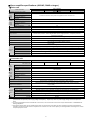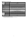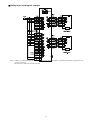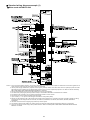
1
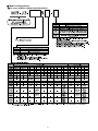
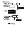
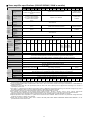
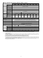
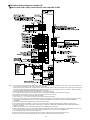
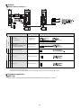
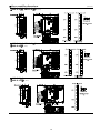
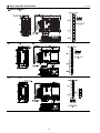
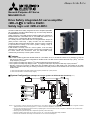
General-Purpose AC Servo MELSERVO-J3 Drive Safety integrated AC servo amplifier <MR-J3-S 0.1kW to 55kW> Safety logic unit <MR-J3-D05> The MR-J3-S Drive Safety integrated AC servo amplifier (SSCNET Ⅲ compatible) and MR-J3-D05 safety logic unit are newly added to the MELSERVO-J3 series. Safety functions of the MR-J3-S and MR-J3-D05 are certified for IEC/EN 61508 SIL 2, EN 62061 SIL CL 2 and EN ISO 13849-1 PL d (Category 3) by a Certification Body (TÜV Rheinland). As a safety function, MR-J3-S has an integrated Safe torque off (STO) function. Safe stop 1 (SS1) function can be realized by combining MR-J3-S with MR-J3-D05. These functions contribute to improvement of safety in the user’s system, making it easy to obtain third-party certification. If MR-J3-B is currently used in a user’s system, it can be easily replaced by the MR-J3-S since both of these servo amplifiers use the same cables and connectors. Also, the MR-J3-S lineup contains fully closed loop control system versions. Features • MR-J3-S and MR-J3-D05 meet IEC/EN 61508 SIL 2, EN 62061 SIL CL 2 and EN ISO 13849-1 PL d (Category 3). Only the Safe torque off (STO)*1 function is integrated into the MR-J3-S. The MR-J3-D05 contains both Safe stop 1 (SS1)*1 and Safe torque off (STO)*1 functions. • User’s system can satisfy stop category 0*2 by using the Safe torque off (STO) function*1. • User’s system can satisfy stop category 0 and 1*2 by using the Safe torque off (STO) and Safe stop 1 (SS1) functions*1. • Mounting, wiring and connectors of MR-J3-S are compatible with those of MR-J3-B. Thus, MR-J3-B can be easily replaced by the MR-J3-S using the existing connections. The safety functions are accessible via the new CN8 connector on the MR-J3-S. *1. Refer to EN IEC 61800-5-2 for details of Safe torque off (STO) and Safe stop 1 (SS1) functions. *2. Refer to EN IEC 60204-1 for details of stop category. System Configurations (example of using 2 systems of STO and SS1 functions) (Note 5) Notes: 1. For prevention of electric shock during maintenance or for protection during servo amplifier fault, be sure to connect a magnetic contactor (MC) between the main power supply and L1, L2 and L3 of the servo amplifier or converter unit. 2. Connect the STO switch signal and forced stop 2 (EM2) signal in connector CN3 of the servo amplifier in addition to the connection with the safety logic unit (MR-J3-D05). 3. Safety logic unit (MR-J3-D05) has 2 independent systems (A-axis and B-axis). 4. All safety-related components such as relays, sensors, etc., must meet the applicable safety standards. 5. Perform risk assessment and safety level certification on the entire machine/system. Model configurations zFor servo amplifier 100VAC/200VAC/400VAC 2 Model configurations zFor drive unit 200VAC/400VAC zFor converter unit 200VAC/400VAC 3 Servo amplifier specifications (100VAC/200VAC, 22kW or smaller) Servo amplifier model Voltage/frequency (Note 1, 2) 10B 20B 40B 60B 70B 3-phase 200 to 230VAC 50/60Hz or 1-phase 200 to 230VAC 50/60Hz 100B MR-J3-S 200B 350B 500B 700B 11KB 15KB 22KB 10B MR-J3-S1 20B 40B 3-phase 200 to 230VAC 50/60Hz 1-phase 100 to 120VAC 50/60Hz 3-phase 170 to 253VAC 1-phase 85 to 132VAC (Note 8) Main circuit power supply For 3-phase 200 to 230VAC: 3-phase 170 to 253VAC For 1-phase 200 to 230VAC: 1-phase 170 to 253VAC Permissible voltage fluctuation (Note 8) Permissible frequency fluctuation Voltage/frequency Permissible voltage fluctuation Permissible frequency fluctuation Power (W) consumption Interface power supply Built-in regenerative Tolerable resistor regenerative External power (W) of regenerative regenerative resistor resistor (standard accessory) ±5% maximum 1-phase 200 to 230VAC 50/60Hz 1-phase 170 to 253VAC Control circuit power supply 1-phase 100 to 120VAC 50/60Hz 1-phase 85 to 132VAC 1-phase 200 to 230VAC 50/60Hz (Note 8) 1-phase 170 to 253VAC (Note 8) ±5% maximum 30 45 30 24VDC±10% (required current capacity: 200mA (including CN8 connector signals) (Note 3)) - 10 10 10 20 20 100 100 130 170 - - - - - - - - - - - - - 500 850 850 (800) (1300) (1300) - 10 10 - - - (Note 5) (Note 5) (Note 5) (Note 4) Control system Dynamic brake Safety features Response performance Sine-wave PWM control/current control system Built-in (Note 7, 9) External option Built-in (Note 7, 9) Overcurrent shutdown, regeneration overvoltage shutdown, overload shutdown (electronic thermal), servo motor overheat protection, encoder fault protection, regeneration fault protection, undervoltage/sudden power outage protection, overspeed protection, excess error protection 20ms or less (STO input OFF → energy shut off) Safety function Safety performance Compliance to standards Structure Ambient temperature (Note 6) Environ- Ambient humidity ment Atmosphere Elevation Vibration STO (EN IEC 61800-5-2) EN ISO 13849-1 PL d (Category 3), IEC/EN 61508 SIL 2, EN 62061 SIL CL 2 CE (LVD: EN 50178, EMC: EN IEC 61800-3) UL (UL 508C) Natural-cooling, open (IP00) Fan-cooling, open (IP00) Natural-cooling, open (IP00) 0 to 55°C (32 to 131°F) (non freezing), storage: -20 to 65°C (-4 to 149°F) (non freezing) 90% RH maximum (non condensing), storage: 90% RH maximum (non condensing) Indoors (no direct sunlight); no corrosive gas, inflammable gas, oil mist or dust 1000m or less above sea level 5.9m/s2 or less at 10 to 55Hz (directions of X, Y and Z axes) 0.8 0.8 1.0 1.0 1.4 1.4 2.1 2.3 4.6 6.2 18 18 19 0.8 0.8 1.0 Mass (kg [lb]) (1.8) (1.8) (2.2) (2.2) (3.1) (3.1) (4.6) (5.1) (10) (14) (40) (40) (42) (1.8) (1.8) (2.2) Notes: 1. Rated output and speed of a servo motor are applicable when the servo amplifier, combined with the servo motor, is operated within the specified power supply voltage and frequency. Torque drops when the power supply voltage is below the specified value. 2. For torque characteristics when combined with a servo motor, refer to the section “Servo motor torque characteristics” in “MELSERVO-J3 catalog L(NA)03017”. 3. 200mA is the value when all of the input/output points are used. The current capacity can be stepped down according to the number of input/output points in use. 4. The value in ( ) applies when the external regenerative resistors, GRZG400- Ω (standard accessory) are used with cooling fans (2 units of 92 x 92mm, minimum air flow: 1.0m3/min). Note that change in parameter No. PA02 is required. 5. Servo amplifiers without an enclosed regenerative resistor are also available: MR-J3- S-PX. 6. The following servo amplifiers can be mounted closely: MR-J3-10 S(1), -20 S(1), -40 S(1), -60 S, -70 S, -100 S, -200 S and -350 S. In this case, operate them at the ambient temperature of 0 to 45°C (32 to 113°F) or at 75% or less of the effective load ratio. 7. Special specification servo amplifiers without a dynamic brake are also available: MR-J3- S-ED and MR-J3- S1-ED. 8. Special specification servo amplifiers for 1-phase 200 to 240VAC are also available: MR-J3- S-U004. The permissible voltage fluctuation for MR-J3- S-U004 is 1-phase 170 to 264VAC. 9. When using the built-in dynamic brake, refer to “MR-J3- B Safety MR-J3-D05 SERVO AMPLIFIER INSTRUCTION MANUAL” for the permissible load inertia moment ratio. 4 Servo amplifier specifications (200VAC, 30kW or larger) z Drive unit MR-J3-DUS Drive unit model 30KB 37KB Compatible converter unit model Main circuit power supply Control circuit power supply MR-J3-CR55K Voltage/frequency (Note 1) Permissible voltage fluctuation Permissible frequency fluctuation Voltage/frequency The drive unit’s main circuit power is supplied from the converter unit. Permissible voltage fluctuation Permissible frequency fluctuation Power consumption (W) 1-phase 170 to 253VAC Interface power supply 1-phase 200 to 230VAC 50/60Hz ±5% maximum 45 24VDC±10% (required current capacity: 200mA (including CN8 connector signals) (Note 3)) Control system Sine-wave PWM control/current control system Dynamic brake External option Overcurrent shutdown, overload shutdown (electronic thermal), servo motor overheat protection, encoder fault protection, undervoltage/sudden power outage protection, overspeed protection, excess error protection 20ms or less (STO input OFF → energy shut off) Safety features Response performance Safety function STO (EN IEC 61800-5-2) Safety performance EN ISO 13849-1 PL d (Category 3), IEC/EN 61508 SIL 2, EN 62061 SIL CL 2 CE (LVD: EN 50178, EMC: EN IEC 61800-3) UL (UL 508C) Fan-cooling, open (IP00) Compliance to standards Structure Ambient temperature 0 to 55°C (32 to 131°F) (non freezing), storage: -20 to 65°C (-4 to 149°F) (non freezing) Ambient humidity 90% RH maximum (non condensing), storage: 90% RH maximum (non condensing) EnvironAtmosphere ment Elevation Indoors (no direct sunlight); no corrosive gas, inflammable gas, oil mist or dust 1000m or less above sea level 5.9m/s2 or less at 10 to 55Hz (directions of X, Y and Z axes) Vibration Mass (kg [lb]) 26 (57) z Converter unit Converter unit model Compatible drive unit model MR-J3-DU S Voltage/frequency (Note 1, 2) Main circuit Permissible voltage fluctuation power Permissible frequency supply fluctuation Control circuit power supply 30KB 37KB 3-phase 200 to 230VAC 50/60Hz 3-phase 170 to 253VAC ±5% maximum Voltage/frequency 1-phase 200 to 230VAC 50/60Hz Permissible voltage fluctuation Permissible frequency fluctuation Power consumption (W) Interface power supply 1-phase 170 to 253VAC ±5% maximum 45 24VDC±10% (required current capacity: 130mA (Note 3)) Regeneration overvoltage shutdown, regeneration fault protection, overload shutdown (electronic thermal), undervoltage/sudden power outage protection CE (LVD: EN 50178, EMC: EN IEC 61800-3) UL (UL 508C) Fan-cooling, open (IP00) Safety features Compliance to standards Structure Ambient temperature 0 to 55°C (32 to 131°F) (non freezing), storage: -20 to 65°C (-4 to 149°F) (non freezing) Ambient humidity 90% RH maximum (non condensing), storage: 90% RH maximum (non condensing) EnvironAtmosphere ment Elevation Indoors (no direct sunlight); no corrosive gas, inflammable gas, oil mist or dust 1000m or less above sea level 5.9m/s2 or less at 10 to 55Hz (directions of X, Y and Z axes) Vibration Mass MR-J3-CR55K (kg [lb]) 25 (55) Notes: 1. Rated output and speed of a servo motor are applicable when the drive unit and converter unit, combined with the servo motor, are operated within the specified power supply voltage and frequency. Torque drops when the power supply voltage is below the specified value. 2. For torque characteristics when combined with a servo motor, refer to the section “Servo motor torque characteristics” in “MELSERVO-J3 catalog L(NA)03017”. 3. The interface power supply can be shared with the drive unit and converter unit. When all of the input/output points are used, 200mA is required for the drive unit, and 130mA is required for the converter unit. The current capacity can be stepped down according to the number of input/output points in use. 5 Servo amplifier specifications (400VAC, 22kW or smaller) Servo amplifier model 60B 100B 200B 350B Voltage/frequency Dynamic brake 11KB 15KB 22KB 3-phase 323 to 528VAC ±5% maximum 1-phase 380 to 480VAC 50/60Hz 1-phase 323 to 528VAC ±5% maximum 30 45 24VDC±10% (required current capacity: 200mA (including CN8 connector signals) (Note 3)) 15 15 100 100 - - - - 130 170 (Note 7) (Note 7) - - - - - 500 (800) 850 (1300) 850 (1300) (Note 5) (Note 5) (Note 5) Sine-wave PWM control/current control system Built-in (Note 6, 8) External option Overcurrent shutdown, regeneration overvoltage shutdown, overload shutdown (electronic thermal), servo motor overheat protection, encoder fault protection, regeneration fault protection, undervoltage/sudden power outage protection, overspeed protection, excess error protection 20ms or less (STO input OFF → energy shut off) Safety features Response performance Safety function STO (EN IEC 61800-5-2) Safety performance Compliance to standards Structure Ambient temperature EN ISO 13849-1 PL d (Category 3), IEC/EN 61508 SIL 2, EN 62061 SIL CL 2 CE (LVD: EN 50178, EMC: EN IEC 61800-3) UL (UL 508C) Natural-cooling, open Fan-cooling, open (IP00) (IP00) 0 to 55°C (32 to 131°F) (non freezing), storage: -20 to 65°C (-4 to 149°F) (non freezing) Ambient humidity 90% RH maximum (non condensing), storage: 90% RH maximum (non condensing) Environment Atmosphere Mass 700B 3-phase 380 to 480VAC 50/60Hz (Note 1, 2) Main circuit Permissible voltage power supply fluctuation Permissible frequency fluctuation Voltage/frequency Permissible voltage Control fluctuation circuit power Permissible supply frequency fluctuation Power (W) consumption Interface power supply Tolerable Built-in regenerative regenerative resistor power (W) of External regenerative regenerative resistor (standard resistor accessory) (Note 4) Control system MR-J3-S4 500B Indoors (no direct sunlight); no corrosive gas, inflammable gas, oil mist or dust Elevation 1000m or less above sea level Vibration 5.9m/s2 or less at 10 to 55Hz (directions of X, Y and Z axes) (kg [lb]) 1.7 (3.7) 1.7 (3.7) 2.1 (4.6) 4.6 (10) 4.6 (10) 6.2 (14) 18 (40) 18 (40) 19 (42) Notes: 1. Rated output and speed of a servo motor are applicable when the servo amplifier, combined with the servo motor, is operated within the specified power supply voltage and frequency. Torque drops when the power supply voltage is below the specified value. 2. For torque characteristics when combined with a servo motor, refer to the section “Servo motor torque characteristics” in “MELSERVO-J3 catalog L(NA)03017”. 3. 200mA is the value when all of the input/output points are used. The current capacity can be stepped down according to the number of input/output points in use. 4. The value in ( ) applies when the external regenerative resistors, GRZG400- Ω (standard accessory) are used with cooling fans (2 units of 92 x 92mm, minimum air flow: 1.0m3/min). Note that change in parameter No. PA02 is required. 5. Servo amplifiers without an enclosed regenerative resistor are also available: MR-J3- S4-PX. 6. Special specification servo amplifiers without a dynamic brake are also available: MR-J3- S4-ED. 7. The amplifier built-in resistor is compatible with the maximum torque deceleration when the motor is used within the rated speed and the recommended load to motor inertia moment ratio. Contact your local sales office if the operating motor speed and the load to motor inertia moment ratio exceed the rated speed and the recommended ratio. 8. When using the built-in dynamic brake, refer to “MR-J3- B Safety MR-J3-D05 SERVO AMPLIFIER INSTRUCTION MANUAL” for the permissible load inertia moment ratio. 6 Servo amplifier specifications (400VAC, 30kW or larger) z Drive unit MR-J3-DUS4 Drive unit model 30KB 37KB Compatible converter unit model Main circuit power supply Control circuit power supply 45KB 55KB MR-J3-CR55K4 Voltage/frequency (Note 1) Permissible voltage fluctuation Permissible frequency fluctuation Voltage/frequency The drive unit’s main circuit power is supplied from the converter unit. 1-phase 380 to 480VAC 50/60Hz Permissible voltage fluctuation Permissible frequency fluctuation Power consumption (W) Interface power supply 1-phase 323 to 528VAC ±5% maximum 45 24VDC±10% (required current capacity: 200mA (including CN8 connector signals) (Note 3)) Control system Sine-wave PWM control/current control system Dynamic brake External option Overcurrent shutdown, overload shutdown (electronic thermal), servo motor overheat protection, encoder fault protection, undervoltage/sudden power outage protection, overspeed protection, excess error protection 20ms or less (STO input OFF → energy shut off) Safety features Response performance Safety function STO (EN IEC 61800-5-2) Safety performance EN ISO 13849-1 PL d (Category 3), IEC/EN 61508 SIL 2, EN 62061 SIL CL 2 CE (LVD: EN 50178, EMC: EN IEC 61800-3) UL (UL 508C) Fan-cooling, open (IP00) Compliance to standards Structure Ambient temperature 0 to 55°C (32 to 131°F) (non freezing), storage: -20 to 65°C (-4 to 149°F) (non freezing) Ambient humidity 90% RH maximum (non condensing), storage: 90% RH maximum (non condensing) EnvironAtmosphere ment Elevation Indoors (no direct sunlight); no corrosive gas, inflammable gas, oil mist or dust 1000m or less above sea level 5.9m/s2 or less at 10 to 55Hz (directions of X, Y and Z axes) Vibration Mass (kg [lb]) 18 (40) 26 (57) z Converter unit Converter unit model MR-J3-CR55K4 Compatible drive unit model MR-J3-DU S4 Voltage/frequency (Note 1, 2) Main circuit Permissible voltage fluctuation power Permissible frequency supply fluctuation Control circuit power supply 37KB 45KB 55KB 3-phase 380 to 480VAC 50/60Hz 3-phase 323 to 528VAC ±5% maximum Voltage/frequency 1-phase 380 to 480VAC 50/60Hz Permissible voltage fluctuation Permissible frequency fluctuation Power consumption (W) Interface power supply 1-phase 323 to 528VAC ±5% maximum 45 24VDC±10% (required current capacity: 130mA (Note 3)) Regeneration overvoltage shutdown, regeneration fault protection, overload shutdown (electronic thermal), undervoltage/sudden power outage protection CE (LVD: EN 50178, EMC: EN IEC 61800-3) UL (UL 508C) Fan-cooling, open (IP00) Safety features Compliance to standards Structure Ambient temperature 0 to 55°C (32 to 131°F) (non freezing), storage: -20 to 65°C (-4 to 149°F) (non freezing) Ambient humidity 90% RH maximum (non condensing), storage: 90% RH maximum (non condensing) EnvironAtmosphere ment Elevation Indoors (no direct sunlight); no corrosive gas, inflammable gas, oil mist or dust 1000m or less above sea level 5.9m/s2 or less at 10 to 55Hz (directions of X, Y and Z axes) Vibration Mass 30KB (kg [lb]) 25 (55) Notes: 1. Rated output and speed of a servo motor are applicable when the drive unit and converter unit, combined with the servo motor, are operated within the specified power supply voltage and frequency. Torque drops when the power supply voltage is below the specified value. 2. For torque characteristics when combined with a servo motor, refer to the section “Servo motor torque characteristics” in “MELSERVO-J3 catalog L(NA)03017”. 3. The interface power supply can be shared with the drive unit and converter unit. When all of the input/output points are used, 200mA is required for the drive unit, and 130mA is required for the converter unit. The current capacity can be stepped down according to the number of input/output points in use. 7 Safety logic unit specifications Safety logic unit model Control circuit power supply MR-J3-D05 Voltage Permissible voltage fluctuation Required current capacity 24VDC 24VDC±10% 500mA (Note 1, 2) Compatible system 2 systems (A-axis, B-axis independent) Shut-off input Shut-off release input Feedback input 4 points (2 points x 2 systems) SDI : source/sink compatible (Note 3) 2 points (1 point x 2 systems) SRES : source/sink compatible (Note 3) 2 points (1 point x 2 systems) Input method Shut-off output Output method Response performance (when delay time is set to 0s) 20ms or less (STO input OFF → shut-off output OFF) A-axis: select from 0s, 1.4s, 2.8s, 5.6s, 9.8s or 30.8s B-axis: select from 0s, 1.4s, 2.8s, 9.8s or 30.8s Accuracy: ±2% STO, SS1 (EN IEC 61800-5-2) EMG STOP, EMG OFF (EN IEC 60204-1) EN ISO 13849-1 PL d (Category 3), IEC/EN 61508 SIL 2, EN 62061 SIL CL 2 Delay time setting Safety function Safety performance Structure Natural-cooling, open (IP00) 0 to 55°C (32 to 131°F) (non freezing), storage: -20 to 65°C (-4 to 149°F) (non freezing) Ambient temperature 90% RH maximum (non condensing), storage: 90% RH maximum (non condensing) Ambient humidity Environment Mass TOF : source compatible (Note 3) Photocoupler insulation, 24VDC (external supply), internal limited resistance 5.4kΩ STO : source compatible (Note 3) 8 points (4 points x 2 systems) SDO : source/sink compatible (Note 3) Photocoupler insulation, Open collector Permissible current: 40mA or less per output, Inrush current: 100mA or less per output Indoors (no direct sunlight); no corrosive gas, inflammable gas, oil mist or dust Atmosphere Elevation 1000m or less above sea level Vibration 5.9m/s2 or less at 10 to 55Hz (directions of X, Y and Z axes) 0.2 (0.44) (including CN9 and CN10 connectors) (kg [lb]) Notes: 1. Inrush current of approximately 1.5mA flows instantaneously when turning the control circuit power supply on. Select an appropriate capacity of a power supply considering the inrush current. 2. Power-ON duration of the safety logic unit is 100,000 times. 3. in signal name represents a symbol which indicates a system number and axis name. 8 Safety logic unit diagram example Notes: 1. CN8A-7 pin (TOF2A) and CN10-8A pin (TOFA) carry the same input signal. CN8B-7 pin (TOF2B) and CN10-8B pin (TOFB) also carry the same input signal. 2. Set delay time of STO output with SW1 and SW2. 9 Standard wiring diagram example (1) z When used with MR-J3-D05 Notes: 1. Do not reverse the diode’s direction. Connecting it backwards may cause the servo amplifier to malfunction such that the signals are not output, and the forced stop and other safety circuits are inoperable. 2. Use the power supply 24VDC±10% (required current capacity: 200mA). 200mA is the value when all of the input/output points are used. Note that the current capacity can be stepped down according to the number of input/output points in use. Refer to “MR-J3- B Safety MR-J3-D05 SERVO AMPLIFIER INSTRUCTION MANUAL” for details. 3. Connect the shield wire securely to the plate inside the connector (ground plate). 4. The malfunction (ALM) signal (normally closed contact) is conducted to DOCOM in normal alarm-free condition. 5. For details on the controllers, refer to relevant programming manual or user’s manual. 6. Connections for the second and following axes are omitted. 7. Up to 16 axes (n = 1 to 16) can be set using the axis selection rotary switch (SW1). 8. Devices can be assigned for DI1, DI2 and DI3 with controller setting. Refer to the controller’s instruction manuals for details on setting. These devices can be assigned with the controller, Q173DCPU, Q172DCPU, Q173HCPU, Q172HCPU, QD75MH, QD74MH or Q170MCPU. 9. Use CN2L connector when configuring fully closed loop control system. 10. Test operation select switch (SW2-1) is used to perform test operation mode with MR Configurator. SW2-2 is a spare switch. 11. This is for sink wiring. Source wiring is also possible. Refer to “MR-J3- B Safety MR-J3-D05 SERVO AMPLIFIER INSTRUCTION MANUAL” for details. 10 Standard wiring diagram example (2) z When used with a safety control device other than MR-J3-D05 Notes: 1. Do not reverse the diode’s direction. Connecting it backwards may cause the servo amplifier to malfunction such that the signals are not output, and the forced stop and other safety circuits are inoperable. 2. Use the power supply 24VDC±10% (required current capacity: 200mA). 200mA is the value when all of the input/output points are used. Note that the current capacity can be stepped down according to the number of input/output points in use. Refer to “MR-J3- B Safety MR-J3-D05 SERVO AMPLIFIER INSTRUCTION MANUAL” for details. 3. Connect the shield wire securely to the plate inside the connector (ground plate). 4. The malfunction (ALM) signal (normally closed contact) is conducted to DOCOM in normal alarm-free condition. 5. For details on the controllers, refer to relevant programming manual or user’s manual. 6. Connections for the second and following axes are omitted. 7. Up to 16 axes (n = 1 to 16) can be set using the axis selection rotary switch (SW1). 8. Devices can be assigned for DI1, DI2 and DI3 with controller setting. Refer to the controller’s instruction manuals for details on setting. These devices can be assigned with the controller, Q173DCPU, Q172DCPU, Q173HCPU, Q172HCPU, QD75MH, QD74MH or Q170MCPU. 9. Use CN2L connector when configuring fully closed loop control system. 10. Test operation select switch (SW2-1) is used to perform test operation mode with MR Configurator. SW2-2 is a spare switch. 11. This is for sink wiring. Source wiring is also possible. Refer to “MR-J3- B Safety MR-J3-D05 SERVO AMPLIFIER INSTRUCTION MANUAL” for details. 12. Attach a short-circuit connector (standard accessory) when invalidating the STO function. 13. When using the STO function, turn off STO1 and STO2 at the same time. Be sure to turn off the STO1 and STO2 after the servo motor stops in servo-off state or after the servo motor stops with deceleration after the forced stop 2 (EM2) turns off. 14. Turn off EM2 when the main circuit power supply is off. 15. If the controller does not have a forced stop function, install the forced stop 2 switch (normally closed contact). 16. Always turn on the forced stop 2 (EM2) signal (normally closed contact) before starting the operation. 11 Options z Cables and connectors (Note 1) Item For CN8 Description MR-D05UDL M = cable length: 0.3, 1, 3m STO cable (2) (for safety control device other than MR-J3-D05) (Note 2) MR-D05UDL3M-B Cable length: 3m (3) Short-circuit connector (Standard accessory) For CN9 For Safety logic unit STO cable (for MR-J3-D05) (4) Connector (Standard accessory) For CN10 For Servo amplifier (1) Model (5) Connector (Standard accessory) Notes: 1. Refer to “MR-J3- B Safety MR-J3-D05 SERVO AMPLIFIER INSTRUCTION MANUAL” for connections with a controller, and for cables and connectors not mentioned in this page. 2. Use this STO cable (MR-D05UDL3M-B) when connecting with a safety control device other than MR-J3-D05. Peripheral equipment z EMC filter Refer to “MR-J3- B Safety MR-J3-D05 SERVO AMPLIFIER INSTRUCTION MANUAL” for details. 12 Servo amplifier dimensions (Unit: mm) z MR-J3-10 S, MR-J3-10 S1 (Note 1) z MR-J3-20 S, MR-J3-20 S1 (Note 1) z MR-J3-40 S, MR-J3-40 S1 (Note 1) z MR-J3-60 S (Note 1) z MR-J3-70 S (Note 1) z MR-J3-100 S (Note 1) Notes: 1. The connectors CNP1, CNP2 and CNP3 (insertion type) are supplied with the servo amplifier. 13 Servo amplifier dimensions (Unit: mm) z MR-J3-60 S4 (Note 1) z MR-J3-100 S4 (Note 1) z MR-J3-200 S, MR-J3-200 S4 (Note 1) z MR-J3-350 S (Note 1) Notes: 1. The connectors CNP1, CNP2 and CNP3 (insertion type) are supplied with the servo amplifier. 14 Servo amplifier dimensions (Unit: mm) z MR-J3-500 S, MR-J3-500 S4 z MR-J3-350 S4 z MR-J3-700 S, MR-J3-700 S4 z MR-J3-11K S, MR-J3-11K S4 z MR-J3-15K S, MR-J3-15K S4 z MR-J3-22K S, MR-J3-22K S4 15 Drive unit dimensions (Unit: mm) z MR-J3-DU30K S z MR-J3-DU37K S z MR-J3-DU45K S4 z MR-J3-DU55K S4 z MR-J3-DU30K S4 z MR-J3-DU37K S4 Notes: 1. The dimension applies when MR-J3BAT is mounted. 16 Converter unit dimensions (Unit: mm) z MR-J3-CR55K, MR-J3-CR55K4 z Panel-cut dimensions for converter unit and drive unit 17 Safety logic unit dimensions (Unit: mm) z MR-J3-D05 18 Warranty 1. Warranty period and coverage We will repair any failure or defect hereinafter referred to as “failure” in our FA equipment hereinafter referred to as the “Product” arisen during warranty period at no charge due to causes for which we are responsible through the distributor from which you purchased the Product or our service provider. However, we will charge the actual cost of dispatching our engineer for an on-site repair work on request by customer in Japan or overseas countries. We are not responsible for any on-site readjustment and/or trial run that may be required after a defective unit are repaired or replaced. [Term] The term of warranty for Product is twelve (12) months after your purchase or delivery of the Product to a place designated by you or eighteen (18) months from the date of manufacture whichever comes first (“Warranty Period”). Warranty period for repaired Product cannot exceed beyond the original warranty period before any repair work. [Limitations] (1) You are requested to conduct an initial failure diagnosis by yourself, as a general rule. It can also be carried out by us or our service company upon your request and the actual cost will be charged. However, it will not be charged if we are responsible for the cause of the failure. (2) This limited warranty applies only when the condition, method, environment, etc. of use are in compliance with the terms and conditions and instructions that are set forth in the instruction manual and user manual for the Product and the caution label affixed to the Product. (3) Even during the term of warranty, the repair cost will be charged on you in the following cases; (i) a failure caused by your improper storing or handling, carelessness or negligence, etc., and a failure caused by your hardware or software problem (ii) a failure caused by any alteration, etc. to the Product made on your side without our approval (iii) a failure which may be regarded as avoidable, if your equipment in which the Product is incorporated is equipped with a safety device required by applicable laws and has any function or structure considered to be indispensable according to a common sense in the industry (iv) a failure which may be regarded as avoidable if consumable parts designated in the instruction manual, etc. are duly maintained and replaced (v) any replacement of consumable parts (battery, fan, smoothing capacitor, etc.) (vi) a failure caused by external factors such as inevitable accidents, including without limitation fire and abnormal fluctuation of voltage, and acts of God, including without limitation earthquake, lightning and natural disasters (vii) a failure generated by an unforeseeable cause with a scientific technology that was not available at the time of the shipment of the Product from our company (viii) any other failures which we are not responsible for or which you acknowledge we are not responsible for 2. Term of warranty after the stop of production (1) We may accept the repair at charge for another seven (7) years after the production of the product is discontinued. The announcement of the stop of production for each model can be seen in our Sales and Service, etc. (2) Please note that the Product (including its spare parts) cannot be ordered after its stop of production. 3. Service in overseas countries Our regional FA Center in overseas countries will accept the repair work of the Product. However, the terms and conditions of the repair work may differ depending on each FA Center. Please ask your local FA Center for details. 4. Exclusion of responsibility for compensation against loss of opportunity, secondary loss, etc. Whether under or after the term of warranty, we assume no responsibility for any damages arisen from causes for which we are not responsible, any losses of opportunity and/or profit incurred by you due to a failure of the Product, any damages, secondary damages or compensation for accidents arisen under a specific circumstance that are foreseen or unforeseen by our company, any damages to products other than the Product, and also compensation for any replacement work, readjustment, start-up test run of local machines and the Product and any other operations conducted by you. 5. Change of Product specifications Specifications listed in our catalogs, manuals or technical documents may be changed without notice. 6. Application and use of the Product (1) For the use of our General-Purpose AC Servo, its applications should be those that may not result in a serious damage even if any failure or malfunction occurs in General-Purpose AC Servo, and a backup or fail-safe function should operate on an external system to General-Purpose AC Servo when any failure or malfunction occurs. (2) Our General-Purpose AC Servo is designed and manufactured as a general purpose product for use at general industries. Therefore, applications substantially influential on the public interest for such as atomic power plants and other power plants of electric power companies, and also which require a special quality assurance system, including applications for railway companies and government or public offices are not recommended, and we assume no responsibility for any failure caused by these applications when used. In addition, applications which may be substantially influential to human lives or properties for such as airlines, medical treatments, railway service, incineration and fuel systems, man-operated material handling equipment, entertainment machines, safety machines, etc. are not recommended, and we assume no responsibility for any failure caused by these applications when used. We will review the acceptability of the abovementioned applications, if you agree not to require a specific quality for a specific application. Please contact us for consultation. Regarding safety standard certification Even though the MR-J3- S servo amplifier and MR-J3-D05 safety logic unit are certified to various safety standards, this does not guarantee that the systems in which they are installed will also be certified. With the entire system in mind, comply strictly with the following: • All safety-related components such as relays, sensors, etc., must meet the applicable safety standards. • For details regarding the use of safety functions and other cautionary information, refer to “MR-J3- B Safety MR-J3-D05 SERVO AMPLIFIER INSTRUCTION MANUAL”. • Perform risk assessment and safety level certification on the entire machine/system. It is recommended to use a Certification Body (TÜV Rheinland, etc.) for final safety certification. 19 Safety Warning To ensure proper use of the products listed in this catalog, please be sure to read the instruction manual prior to use. L(NA)03048ENG B 0909 Printed in Japan (MDOC) New publication, effective September 2009 Specifications subject to change without notice.