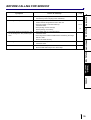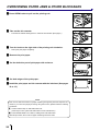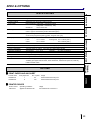
1
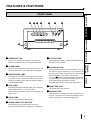
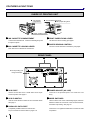
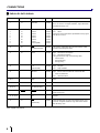
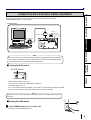
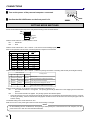
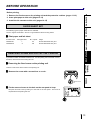
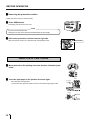
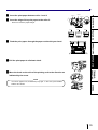
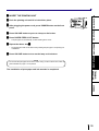
DIGITAL COLOR PRINTER
MODEL
CP800DW
OPERATION MANUAL
CP800DW
PAPER FEED
&CUT
ALARM
SHEET/PAPER
SCSI
COPY
ONLINE
DATA
POWER
OPEN
THIS OPERATION MANUAL IS IMPORTANT
TO YOU.
PLEASE READ IT BEFORE USING YOUR
DIGITAL COLOR PRINTER.
This digital colour printer complies with the requirements of the EC
Directive 89/336/EEC, 73/23/EEC and 93/68/EEC.
The electro-magnetic susceptibility has been chosen at a level that
gains proper operation in residential areas, on business and light
industrial premises and on small-scale enterprises, inside as well as
outside of the buildings. All places of operation are characterised by
their connection to the public low voltage power supply system.
CONTENTS
PRECAUTIONS
CONTENTS
SAFETY PRECAUTIONS ..................................................................... 2-4
FEATURES & FUNCTIONS .................................................................. 5-6
FRONT PANEL ...................................................................................... 5
INSIDE OF PRINTING UNIT ................................................................. 6
FEATURES
REAR PANEL ........................................................................................ 6
CONNECTIONS .................................................................................... 7-10
CONNECTION WITH PARALLEL DATA INTERFACE ......................... 7-8
CONNECTION WITH SCSI DATA SIGNAL EQUIPMENT .................... 9
CONNECTIONS PREPARATION
SETTING MODE SWITCHES ................................................................ 10
BEFORE OPERATION ......................................................................... 11-17
PAPER SHEET SET .............................................................................. 11
REMOVING PRINTING UNIT FIXING SCREW AND
PROTECTIVE CUSHION ................................................... 11-12
INSERTION OF PRINT PAPER ............................................................ 12-13
INSERTION OF INK SHEET ................................................................. 14-15
USAGE AND KEEPING OF PAPER SHEET SET ................................. 16
INSTALLING PRINTER DRIVER ........................................................... 17
INDICATION ON THE FRONT PANEL & COUNTERMEASURES ...... 18
OVERCOMING PAPER JAMS & OTHER BLOCKAGES ..................... 20
SPEC & OPTIONS ................................................................................ 21
TROUBLESHOOTING
BEFORE CALLING FOR SERVICE… .................................................. 19
OTHERS
1
SAFETY PRECAUTIONS
In the interest of safety, please observe the following precautions:
POWER REQUIREMENT
This Digital Color Printer is designed to operate on 120V, 60Hz AC in U.S.A. and Canada, 220-240V, 50Hz AC in Europe. Never
connect to any outlet or power supply having a different voltage or frequency.
WARNING: THIS APPARATUS MUST BE EARTHED.
AVERTISSEMENT: CET APPAREIL DOIT ETRE MIS A LA TERRE.
PROTECTIVE MEASURES
IF ABNORMALITIES ARISE, .....
Use of the unit during emission of smoke or abnormal sounds (without adopting countermeasures) is dangerous. In such a case,
unplug the power cord from the source outlet immediately, and request maintenance service from the sales dealer.
NEVER INSERT ANY OBJECT INTO THE UNIT
Foreign objects of any kind inserted into this unit constitute a safety hazard and can cause extensive damage.
DO NOT PLACE ANYTHING ON THE DIGITAL COLOR PRINTER
Heavy objects placed on the Digital Color Printer can cause damage or obstruct proper ventilation.
PROTECT THE POWER CORD
Damage to the power cord may cause fire or shock hazard. When unplugging, hold by the plug only and remove carefully.
DO NOT PLACE WATER CONTAINERS ON THE UNIT
Do not place flower vases, and other water-holding containers on the device. If, for some reason, water seeps to the inside of the
unit, unplug the power cord from the source outlet, and contact the sales dealer. If used without corrective measures, the unit may
be damaged.
"In the interest of safety, avoid handling of liquids near the unit."
DO NOT REMOVE THE CABINET
Touching internal parts is dangerous, besides, it may lead to malfunction. Contact the sales dealer to carry out internal checks and
adjustments. Before opening the cover for eliminating a jammed paper, etc., be sure to disconnect the power cord plug.
UNPLUG THE POWER CORD DURING A LONG ABSENCE
Turn off the MAIN power switch and unplug the power cord during a long absence.
WHEN TRANSPORTING THE UNIT
When transporting the unit, remove the sheet cartridge and paper from the paper holder, and insert the protective cushion into its
compartment. Make sure to screw the printing unit down.
BE CAREFUL AROUND PRINT PAPER EXIT SLOT
Don't insert your hand or any material into the paper exit slot during printing.
Don’t touch the cutter blade inside the paper exit slot.
Otherwise, your finger will be injured.
DO NOT TOUCH THE THERMAL HEAD
Do not touch your hand to the thermal head (located inside the unit).
The thermal head is heated to high temperature.
This may cause injury.
2
BE CAREFUL WITH THE PRINTING UNIT
PRECAUTIONS
Don’t move the unit while the printing unit is sliding out. This may cause injury.
Be careful not to catch your finger in the printing unit while the printing unit is being retracted into the unit.
CONNECTION CABLES
Use the provided power cord. When connecting the unit with an equipment with parallel data interface, use the parallel cross-over
cable.
FEATURES
INSTALLATION LOCATIONS
MAINTAIN GOOD VENTILATION
Ventilation slots and holes are provided on the sides and bottom of this unit. Place the unit on a hard and level surface and at least
CONNECTIONS PREPARATION
10cm from walls to insure proper ventilation. When putting the unit on the system rack, provide a space between the unit and the
back of the rack.
UNSUITABLE LOCATIONS
Avoid shaky places or hot-springs areas where hydrogen sulfide and acidic ions are likely to be generated.
PLACES WITH HIGH HUMIDITY AND DUST
Do not place the unit at a high humidity and dusty locations. They can cause extensive damage to the printer. Avoid places where
the unit is likely to be exposed to oily fumes and vapors.
PLACES NOT LIKELY TO BE EXTREMELY HOT
Places exposed to direct sunlight, or near heating appliances can attain extremely high temperatures, which may deform the
cabinet, or can become a prime cause of damage.
PLACE THE UNIT ON A HORIZONTAL LEVEL
PROTECT AGAINST DEW FORMATION
In extremely cold regions, if the unit is moved quickly from an extremely cold place to warmer one, dew is likely to be formed.
If dew is formed, printing is not possible.
TROUBLESHOOTING
The printer performance is likely to be affected if it is placed in slanted conditions or in an unstable places.
OPERATING AMBIENT TEMPERATURE RANGE
OTHERS
The operating ambient temperature range is 5˚C-40˚C and the humidity of 20-80%. These conditions must be maintained under
any setup including system rack mounts.
FOR LONG OPERATING LIFE
UNSUITABLE MATERIALS FOR THE DIGITAL COLOR PRINTER
Coat flaking and deformation are likely to occur if the unit is wiped with chemical dusters, benzine, thinner or any other solvent, if
rubber or PVC items are left in contact with the unit for extended duration, or if the unit is sprayed with insecticide.
CARE OF THE CABINET
Unplug and clean with a soft cloth slightly moistened with a mild soap and water solution. Allow to dry completely before operating.
Never use petroleum base solutions or abrasive cleaners.
HEAD ABRASION
The thermal head, like the video head, wears out. When it is abraded, it becomes hard to print out fine details of the picture. In such
a case, it is necessary to replace the thermal head. Consult with the sales dealer for replacing the head.
3
SAFETY PRECAUTIONS
CONNECTING DEVICES
Read thoroughly "Operating Precautions" of the instruction booklets for the devices connected with the Digital Color Printer.
The power cord must be disconnected after printing is over.
CAUTION ON RELOCATING
When transporting this unit, make sure it is not likely to be subjected to impacts. They can be a prime cause for damage. Further,
make sure to disconnect the power cord from the power outlet, and the cables from the connected devices.
OTHER CAUTIONS
Dust or other foreign matter adhering to the print paper or the sheet cartridge, or deformation resulting from exposure to extremely
low or high temperatures could cause loss of color, uneven color or lines, or wrinkles in the print images.
NOTE:
YOUR UNDERSTANDING IS REQUESTED FOR THE LOSS OF IMAGES IN MEMORY DUE TO THE SUDDEN OCCURRENCE
OF A MALFUNCTION.
As for paper sheet set, refer to "Paper sheet set".
4
FEATURES & FUNCTIONS
2345
6
7
PRECAUTIONS
FRONT PANEL
8
FEATURES
CP800DW
PAPER FEED
&CUT
ALARM
SCSI
COPY
ONLINE
DATA
POWER
1 POWER BUTTON
Press to turn on power. Press again to turn off power.
When the power is turned on, the indicator illuminates.
When this unit is overheated, this indicator goes on and
off. When other error occurs, it illuminates. See page 18.
3 SHEET/PAPER LAMP
See page 18 “INDICATION ON THE FRONT PANEL &
COUNTERMEASURES”.
4 SCSI LAMP
Illuminates when SCSI is selected (when OFF is selected)
at the MODE switch No. 1 on the rear panel.
When selecting PARALLEL (when ON is selected), the
lamp is not lit.
5 DATA LAMP
7 COPY BUTTON
Prints image from memory. When ON LINE indicator is lit,
this button is not functional.
8 ON LINE BUTTON
Press to switch the PC connection between on and off
line. When on line is selected, you can control this unit
through your PC. When on line is selected, a lamp on this
button illuminates. Press again to select off line.
If you press COPY button while holding down this but-
7
OTHERS
Illuminates when ink sheets or print paper are used up or
any trouble occurs in the sheet cartridge or print paper.
9
A
TROUBLESHOOTING
2 ALARM LAMP
OPEN
CONNECTIONS PREPARATION
1
SHEET/PAPER
ton when the lamp on this button illuminates, this unit continues printing till the print paper is used up.
Press ON LINE button to cancel continuous printing.
9 PRINT EXIT SLOT
The printed paper come out here.
A OPEN BUTTON
When this button is pressed, the printing unit advances to
the front. The printing unit is used when installing ink cassette and print paper or overcoming paper jams.
Goes on and off during transferring data.
6 PAPER FEED & CUT BUTTON
Pressing this button, the print paper is fed and cut.
When ON LINE indicator is lit, this button is not functional.
5
FEATURES & FUNCTIONS
INSIDE OF PRINTING UNIT
2 Ink cassette locking lever
3 Print paper fixing lever
1 Ink cassette
compartment
4 Paper sending control
1 INK CASSETTE COMPARTMENT
3 PRINT PAPER FIXING LEVER
Load the ink cassette here. Insert the cassette gently until
it snaps into place.
Use this lever when inserting print paper.
4 PAPER SENDING CONTROL
2INK CASSETTE LOCKING LEVER
Turn this control clockwise to rewind the print paper.
Push this lever to take the ink cassette out.
REAR PANEL
1
2
SCSI
ID No.
Store the printing unit
fixing screw here.
ON
SCREW
OFF
1 2 3 4 5 6 7 8
12345678
DIRECT SNAP
ACK
ON PARALLEL
OFF SCSI
1 SCSI PORT
Used to connect this unit to a SCSI device such as personal computers. See page 9.
2 SCSI ID SWITCH
Used to set the SCSI ID number of the connected device.
See page 9.
3 PARALLEL DATA PORT
Compatible parallel interface for Centronics®.
For pin connections see the table on pages 7-8.
6
PARALLEL
AC LINE
3
4
5
4 POWER SOCKET (AC LINE)
Connects to the provided power cord. Insert the cord
firmly.
5 MODE SWITCHES
Used to set the time of the acknowledge signal, selection
between PARALLEL and SCSI of the connected device,
and direct snap setting. See page 10.
Centronics® is a registered trademark of Centronics Data
Corporation.
CONNECTIONS
Make sure to turn off main power of the unit and other equipment before connection.
PRECAUTIONS
CONNECTION WITH PARALLEL DATA INTERFACE
CONNECTION
PIN NO.
To PARALLEL
DATA terminal
MODE switches
1
36
19
FEATURES
To PARALLEL port
18
ID No.
CONNECTIONS PREPARATION
Connector :JD36SL equivalent
(36-pin)
SCSI
ON
SCREW
OFF
1 2 3 4 5 6 7 8
12345678
DIRECT SNAP
ACK
ON PARALLEL
OFF SCSI
PARALLEL
AC LINE
Input level :TTL
PARALLEL input connector port
:signal allocation
Personal computer
Digital Color Printer
See next page for PARALLEL
DATA SIGNALS.
TROUBLESHOOTING
OTHERS
7
CONNECTIONS
2
PARALLEL DATA SIGNAL
Pin No.
Return pin No.
Signal
From/to
Function
1
19
STROBE
PC/DCP
Strobe pulse for data reading. Incoming pulse width should
be 0.5 ms minimum. At regular conditions, “High” data will be
read after becoming “Low”.
2
3
4
5
6
7
8
9
20
21
22
23
24
25
26
27
DATA1 (LSB)
DATA2
DATA3
DATA4
DATA5
DATA6
DATA7
DATA8 (MSB)
PC/DCP
PC/DCP
PC/DCP
PC/DCP
PC/DCP
PC/DCP
PC/DCP
PC/DCP
High: data 1
Low: data 0
Information will be expressed for parallel data of every signal
from bit No.1 to No.8.
10
28
ACK
(ACKNOWLEDGE)
DCP/PC
This signal is yielded after data input has ended by a data
reception acknowledgment pulse.
11
29
BUSY
DCP/PC
High: DCP data is not accepted
Low: DCP data is accepted
The signal becomes “High” in the following cases;
· Off line status
· During data entry
· During printing
12
P·E
(PAPER END)
DCP/PC
High:
Low:
13
SELECT
DCP/PC
High: INPUT switch is PARALLEL and the ON LINE
button is pressed ON
Low: Other than above
16,17
GND
18
DC5V
19-30, 33
for twist pair return
32
FAULT
14, 15, 34-36
31
Earth
DCP/PC
16
INT
(INITIALIZE)
Low: Abnormal condition occurs in DCP (e.g. error due to
paper jamming etc.)
Unused
NC
DCP : Digital Color Printer
8
FAULT
No paper
Paper available
PC/DCP
Clears sending data. Incoming pulse width should be 100 ms
minimum. At regular conditions, “High” data will be cleared
after becoming “Low”.
PRECAUTIONS
CONNECTION WITH SCSI DATA SIGNAL EQUIPMENT
Make sure to turn off main power of the unit and other equipment before connection.
Set the MODE switch No. 1 to OFF (SCSI).
(CONNECTION)
FEATURES
Terminator
To SCSI port
ID No. switch
To SCSI port
CONNECTIONS PREPARATION
SCSI
ID No.
ON
SCREW
OFF
1 2 3 4 5 6 7 8
12345678
DIRECT SNAP
ACK
ON PARALLEL
OFF SCSI
PARALLEL
AC LINE
Digital Color printer
Personal computer
NOTE
When this unit is not connected to the other equipment through another SCSI port, make
sure to attach a terminator on the SCSI port which is not used. See the operation manual
of an equipment to be connected for attaching terminator.
TROUBLESHOOTING
2
Setting SCSI ID switch
SCSI ID switch
OTHERS
ID No.
Select the ID number among 1 to 6.
Turn the arrow to set the ID number with a screwdriver.
The default setting is No. 5.
No. 7 is provided for personal computer you use and No. 0 is provided for a built-in hard disk.
Do not set the ID number to the same setting as the connected equipment.
NOTE
Make sure to turn on the power again when SCSI ID number is changed with the power
turned on.
2
Setting ON LINE status
1 Press POWER button to turn on this unit.
POWER
The lamp over the POWER button is lit.
9
CONNECTIONS
2 Turn on the power of the personal computer connected.
PAPER FEED
& CUT
COPY
ONLINE
3 Confirm that ON LINE button on the front panel is lit.
SETTING MODE SWITCHES
Set the mode switches (DIP-SW) on the rear panel according to the connected device.
ON
1 2 3 4 5 6 7 8
OFF
12345678
DIRECT SNAP
ACK
ON PARALLEL
OFF SCSI
With the mode switch No.1, switch parallel or SCSI.
ON .......... PARALLEL
OFF ........ SCSI
With the mode switches No. 2, No. 3 and No. 4, set the time of acknowledge signal (ACK).
Refer to the operation manual of the connected personal computer for the set time.
Mode switch No.
2
3
ACK time
4
Switching position
OFF(down) OFF(down) OFF(down)
0.5µs
OFF(down) OFF(down) ON(up)
1.0µs
ON(up)
OFF(down) OFF(down)
1.5µs
ON(up)
OFF(down) ON(up)
2.0µs
OFF(down) ON(up)
OFF(down)
2.5µs
OFF(down) ON(up)
ON(up)
3.0µs
ON(up)
ON(up)
OFF(down)
3.5µs
ON(up)
ON(up)
ON(up)
4.0µs
With the mode switches No. 5, No. 6 and No. 7, select the printing result when connecting with DS-300 (FUJIX digital camera).
Mode switch No.
5
6
Switching position
OFF(down) ON/OFF
7
ON/OFF
Printing result
Normal print
(Print connecting with a personal computer)
Print image will not be enlarged.
ON(up)
OFF(down) ON/OFF
ON(up)
ON(up)
OFF(down) Print image will be enlarged to 137.5%.
ON(up)
ON(up)
ON(up)
Print image will be enlarged to 137.5% and
white frame will be made around the image.
With the mode switch No. 8, set whether the surface lamination is applied or not.
ON .......... The surface lamination is not applied. The printing speed will get faster due to the skipping surface lamination
process.
OFF ........ The surface lamination is applied. The printing speed is the standard speed.
• When this switch is set to ON, the printing speed will get faster due to the skipping surface lamination process. However,
the life, light stability, moisture resistance and fingerprint resistance will be as the same level as the print paper without
surface coating.
The default setting of the mode switches is OFF.
Make sure to turn on the power again when the mode switch setting is changed.
NOTE
•
10
On the initializing function invalid status, when printing is interrupted by the command from the host computer, turn the
power of this unit to OFF and clear the transferred data.
BEFORE OPERATION
Before printing,
PRECAUTIONS
1. Remove the fixed screw on the printing unit and the protective cushion. (pages 11-12)
2. Insert print paper to this unit. (pages 12-13)
3. Install the ink cassette to this unit. (pages 14-15)
PAPER SHEET SET
FEATURES
The following types of paper sheet sets are available.
Use our original consumable. We can not guarantee the failure of using others.
2
Print paper and ink sheet
CK800FL4P
CK800FS4P
Print paper size
L
S
No. of prints
60
100
CONNECTIONS PREPARATION
Product name
Usage
Surface-laminated color print
Surface-laminated color print
REMOVING SCREW AND PROTECTIVE CUSHION
A protective cushion is inserted inside this unit. And the printing unit is fixed with a screw,
therefore, remove them before using this unit.
Removing the fixed screw on the printing unit
TROUBLESHOOTING
2
There is a fixed screw at the bottom of the printing unit.
1 Remove the screw with a screwdriver or a coin.
Keep the removed screw by setting it to the hole on the rear panel. This screw is
required when transporting this unit.
OTHERS
▼
2 Fix the removed screw to the hole on the rear panel to keep.
Fixed screw
▼ Storing position
SCSI
ID No.
ON
SCREW
OFF
1 2 3 4 5 6 7 8
12345678
DIRECT SNAP
ACK
ON PARALLEL
OFF SCSI
PARALLEL
AC LINE
11
BEFORE OPERATION
2
Removing the protective cushion
Unplug the power cord from outlet for safety.
1 Press OPEN button.
The printing unit advances to the front.
NOTE
Do not touch the thermal head.
Fingerprints or dust on the thermal head will degrade the print quality.
2 Pull out the protective cushion from the right side.
Keep the removed cushion. It is required when transporting this unit.
Protective cushion
INSERTION OF PRINT PAPER
1 Move the knob on the printing unit to the direction indicated by the
1
arrow.
2 Insert the print paper in the position as shown right.
·
·
Holder
Print paper
Place the gear to the right side.
To set the left side, press the holder in the unit and insert the print paper roller.
Insert into ditch
Holder
Print paper
12
·
Roller 2
Roller 3
Fron
t
Roller 1
Be sure to insert the paper straight.
Print paper
Roller
Roller
Paper
Paper
Paper
INCORRECT
CORRECT
CONNECTIONS PREPARATION
5 Feed the print paper through the paper outlet with your hand.
6 Pull the print paper to eliminate slack.
indicated by the arrow.
·
OTHERS
FEED & CUT button.
1
TROUBLESHOOTING
7 Move the knob on the side of the printing unit to the direction as
NOTE
If too much paper is fed, ALARM lamp may light. In this case, press PAPER
INCORRECT
FEATURES
Roller
PRECAUTIONS
3 Insert the print paper between roller 1 and 2.
4 Insert the edge of the print paper to the roller 3.
13
BEFORE OPERATION
INSERTION OF INK SHEET
2
INSTALLING THE INK SHEET
White roller
C
Install the ink sheet to the ink cassette before installing the ink cassette to the unit.
1 Put the colored roller of the ink sheet to the ink cassette. AB
2 Put the thin stick of white roller to the ink cassette. C
3 Put the thick stick of white roller to the ink cassette. DE
D
·
On the
position, turn the roller and set the notch of the roller side to the hole of
the cassette.
E
B
A
Colored roller
E
D
hole
The roller can be installed when the notch is put through the hole.
2
INSTALLING THE INK CASSETTE
1 Eliminate any slack of the ink sheet.
·
Hold the colored roller and turn the white roller.
2 Insert the ink cassette with the ink sheet into its compartment.
·
Insert the ink cassette with the knob side toward you until it is locked into place.
When taking the ink cassette out of the compartment, press the ink cassette locking
holder to release the lock. Refer to Page 6.
14
notch
INSERT THE PRINTING UNIT
1 Push the printing unit until it is locked into place.
2 After plugging the power cord, press POWER button on the front
panel.
•
The print paper is automatically cut after feeding about 10cm.
•
Fingerprints and dust can be removed by feeding the print paper. The printing unit
is initialized.
6 Press ON LINE button to turn on the lamp on the button.
NOTE
Do not feed the print paper more than 2 times. Doing so will not allow the number of
prints indicated on page 11 to be printed.
CONNECTIONS PREPARATION
5 Repeat the above step 4.
FEATURES
3 Press ON LINE button to put out a lamp on the button.
4 Press PAPER FEED & CUT button.
PRECAUTIONS
2
The installation of print paper and ink cassette is completed.
TROUBLESHOOTING
OTHERS
15
BEFORE OPERATION
USAGE AND KEEPING OF PAPER SHEET SET
NOTE
•
Fingerprints or dust on the paper’s surface may degrade print quality and cause
paper jams. Immediately after the paper is replaced, 2-3 images may be printed
with a blank part due to hand’s dust or oil.
•
When print paper is rapidly transferred from a cool place to a hot place, vapor or
dew will be generated on the paper’s surface causing paper jams or degraded
print quality. Leave the print paper in the room to stabilize its temperature before using it.
•
When print paper and ink sheet runs out during printing, the printing operation
stops and “SHEET/PAPER” lamp on the front panel is lit.
•
If paper feeding is repeated while installing the print paper, the indicated number of prints may not be done.
2
AFTER PRINTING
Surface-laminated print paper which is durable and keeps picture quality is suitable for this
unit. If using print paper without surface laminating, please pay attention to the following
points.
•
When the printed paper is touched by a wet hand, the print may be discolored.
•
Fading may occur if the print-face is exposed to organic chemical agents which may
affect print paper (e.g., alcohol, ester, ketone based). Fading will be accelerated upon
contact with PVC-based materials (e.g., adhesive tapes, rubber erasers, etc.).
2
STORAGE
•
Leaving the print paper in contact with PVC- based materials causes color of print
paper to come off and to be stained.
•
Never store print paper in places that are hot, humid or places exposed to direct sunlight, otherwise color will fade.
Keep print paper in a place where;
temperature : 5 – 40 C
humidity
•
: 20 – 80 %RH
If the print paper is installed for two or more days, the prints may be rolled after printing.
There is no cause for alarm because the print paper is rolled on the inside of the printing unit.
16
Printer driver is required to print the data from a personal computer connected with this
unit.
CPD-04 and CPD-05 are supplied with this unit.
CPD-01NT
Version 2.4 or later
CPD-04
Operating conditions
Applies for WindowsNT® Workstation operating system Version 4.0
Applies for Microsoft® Windows® 95 or later
CPD-05
Version 2.3 or later
Applies for Macintosh System 7.0 or later
Refer to the operation manual of the driver software or “Read me” for installing.
Macintosh is a trademark of Apple Computer Inc.
Windows® 95 and WindowsNT® are trademarks of the Microsoft Corporation.
Microsoft® is a registered trademark of the Microsoft Corporation.
CONNECTIONS PREPARATION
Version 2.3 or later
FEATURES
Product name
PRECAUTIONS
INSTALLING PRINTER DRIVER
TROUBLESHOOTING
OTHERS
17
INDICATION ON THE FRONT PANEL & COUNTERMEASURES
INDICATION ON THE FRONT PANEL
If for some reason printing is not possible or error occurs during printing, the indicator on the front panel will be lit.
In this case, follow the procedure described below.
:Lit
ALARM
SHEET/PAPER
●
(goes on
and off)
SCSI
●
●
●
DATA
●
●
●
●
●
●
●
● : Not lit
Cause and Countermeasures
Print paper is not set.
Print paper is not set correctly.
Print paper runs out during printing. *Note : 1
• Set the print paper correctly.
The ink cassette is not installed. *Note: 2
• Install the ink cassette.
The ink sheet is used up.
• Replace the ink sheet with a new one.
The temperature of the thermal head becomes too high.
• Wait until the lamp goes off. *Note: 3
Paper jamming occurs.
• Refer to “Overcoming paper jams”.
Other defects
• When the ON LINE lamp is not lit, press PAPER FEED &
CUT button. *Note: 4
If the status is not improved by carrying out this measure,
consult your dealer.
Page
12-13
14-15
20
12-13
*Note 1 : When the print paper runs out, the image is not printed completely.
*Note 2 : The lamp goes on and off after transferring data and just before starting printing operation.
*Note 3 : When setting the continuous printing, the continuous printing is carried out after the lamp goes off.
*Note 4 : When the printing unit is pulled out, PAPER FEED & CUT button is invalid.
After pushing the printing unit until it is locked into place, press the PAPER FEED & CUT button.
When this error occurs during printing on L size paper, carry out this procedure twice.
18
BEFORE CALLING FOR SERVICE
Symptom
Check & Remedy
No power
• Is the power cord plug disconnected from the outlet?
Connect the power cord plug to the outlet firmly.
The image is not printed.
• Is the image data sent to this unit?
Confirm that the image data is sent to this unit.
7-10
• Is the print paper or ink sheet used up?
Check the status.
12-15
15
The image stored in the memory can
not be enlarged to the possible print
• Is the image data of L-size transferred?
Check the status.
-
area.
• Is the large size ink sheet installed when transferring the image
data of L-size?
-
Set the ink sheet correctly.
• Is the ON LINE lamp lit?
5
COPY button does not work.
Check the status.
• Is the ON LINE lamp lit?
5
Press the ON LINE lamp to turn off the lamp.
CONNECTIONS PREPARATION
The image can not be transferred.
FEATURES
• Is the printing unit set correctly?
Set the printing unit correctly.
-
PRECAUTIONS
Reference
page
TROUBLESHOOTING
OTHERS
19
OVERCOMING PAPER JAMS & OTHER BLOCKAGES
1 Press OPEN button to pull out the printing unit.
2 Take out the ink cassette.
•
Push the ink cassette locking lever to unlock the ink cassette. (See page 6.)
3 Turn the knob on the right side of the printing unit clockwise.
•
Roll up the print paper completely.
4 Remove the print paper.
5 Cut the defective part of print paper with scissors.
6 Cut both edges of the print paper.
7 Install the print paper and ink cassette with the ink sheet. (See pages
12 to 15.)
NOTE
This unit can detect the amount of paper remaining through the personal computer connected. If you overcome paper jam during using the function, please follow the following
procedures.
Confirm that the lamp on ON LINE button is lit.
1
(If the lamp is not lit, press ON LINE button to have it illuminated.)
2 Press PAPER FEED & CUT button, holding down ON LINE button.
With this procedure, the counter for paper remaining will not be reset.
20
SPEC & OPTIONS
Class
Digital Color Printer
Model
Printing method
CP800DW
Sublimation Dye Thermal Transfer line print
Print quality
Print’s resolution 1280 pixels x 1040 lines (S size)
1280 pixels x 1768 lines (L size)
PRECAUTIONS
SPECIFICATIONS
Gradations
256 for each color
L size : Approx. 69sec/sheet (Surface-laminated paper)
Ink-sheet
S size : Approx. 43sec/sheet (Surface-laminated paper)
Special cartridge method
Print paper
3 color faces progressive printing (yellow, magenta and cyan)
Special roll paper
127 x 178mm
127 x 102mm
Printing area 127 x 178mm (max.)
127 x 102mm (max.)
Supply method
Input/Output terminal
Automatic
Micro mini 50 pin
Power supply
Power consumption
AC 220-240V, 50/60Hz AC 120V, 50/60Hz
1.0A (220-240V AC, 50Hz), 1.6A (120V AC, 60Hz) during printing
Operating conditions
Installation conditions
Temperature :
5 C - 40 C
Humidity :
Operating attitude :
Horizontal –5
Outside dimensions
Weight
280(W) x 150(H) x 398(D) mm
14.5kg
Standard accessories
Power cords (for 120V and 220V), Ink cassette, Spacer(4), Operation manual, Sheet
“Installing print paper and ink sheet”, SCSI Terminator, Printer driver (CPD-04, CPD-05),
Parallel data interface (36 pin)
20 - 80% (no dewing)
Label for MODE switch
2
PRINT PAPER AND INK SHEET
CK800FS4P
2
Print paper size
L
S
No. of prints
60
100
Usage
Surface-laminated color print
Surface-laminated color print
PRINTER DRIVER
Product name
CPD-01NT
Operating conditions
Applies for Windows NT®
OTHERS
Product name
CK800FL4P
TROUBLESHOOTING
OPTIONS
CONNECTIONS PREPARATION
L size
S size
FEATURES
Printing time
Usage
For Windows NT® Version 4.0
21
MITSUBISHI ELECTRONICS AMERICA, INC.
5665 PLAZA DRIVE P.O. BOX 6007
CYPRESS, CA 90630 – 0007, USA
Mitsubishi Electric Europe B.V.
UK Branch
Travellers Lane, Hatfield, Herts. AL10 8XB, England, U.K.
Phone (1) 707 276100
FAX (1) 707 278755
German Branch
Gothaer Strasse 8, Postfach 1548, 40880 Ratingen 1, Germany
Phone (2102) 4860
FAX (2102) 486-732
French Branch
25, boulevard des Bouvets - 92741 NANTERRE cedex
Phone (01) 55.68.55.00
FAX (01) 55.68.57.31
Italian Branch
Centro Direzionale Colleoni, Palazzo Perseo-Ingresso 2,
Via Paracelso 12, 20041 Agrate Brianza, (Milano) Italy
Phone (039) 60531
FAX (039) 6057694
Benelux Branch
Nijverheidsweg 23 A, 3641 RP. Postbus 222, 3640 AE Mijdrecht
Phone 02972-82461
FAX 02972-83936
Spanish Branch (Barcelona)
Sucursal en españa
Polígono Industrial "Can Magí", Calle Joan Bucallà 2-4,
Apartado de Correos 420, 08190 Sant Cugat del Vallês,
Barcelona, Spaín
Phone (3) 589-3900
FAX (3) 589-4448
Made from recycled paper
PRINTED IN JAPAN
871C958D2