1
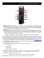
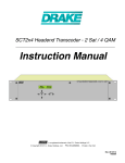
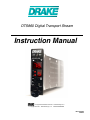
DTS860 Digital Transport Stream
Instruction Manual
is a registered trademark of the R.L. Drake Holdings LLC
© Copyright 2013 R. L. Drake Holdings, LLC
P/N: 651230000A
Rev: 20130130
1002575
2
Table of Contents, Caution, & Important Safety Instructions
Caution Statements ......................................................................................................................................2
Important Safety Instructions ...............................................................................................................2
Specifications .................................................................................................................................................4
front panel controls..................................................................................................................................5
operation...........................................................................................................................................................7
Warranty ..........................................................................................................................................................10
Caution Statements:
WARNING: TO PREVENT FIRE OR
ELECTRICAL SHOCK, DO NOT
EXPOSE TO RAIN OR MOISTURE
A product and cart combination should be moved
with care. Quick stops, excessive force and uneven
surfaces may cause the product and cart combination
to overturn.
The lightning flash with arrow head symbol, within an
equilateral triangle, is intended to alert the user to the
presence of uninsulated "dangerous voltage" within
the product's enclosure that may be of sufficient
magnitude to constitute a risk of electric shock to
persons.
The exclamation point within an equilateral triangle is
intended to alert the user to the presence of important
operating and maintenance (servicing) instructions in
the literature accompanying the product.
WARNING:
TO REDUCE THE RISK OF FIRE OR ELECTRIC SHOCK, DO NOT EXPOSE THIS PRODUCT TO
RAIN OR MOISTURE.
DO NOT OPEN THE CABINET, REFER SERVICING TO QUALIFIED PERSONNEL ONLY.
CAUTION:
TO PREVENT ELECTRIC SHOCK, DO NOT USE THIS (POLARIZED) PLUG WITH AN EXTENSION
CORD RECEPTACLE OR OTHER OUTLET UNLESS THE BLADES CAN BE FULLY INSERTED TO
PREVENT BLADE EXPOSURE.
ATTENTION: P
OUR PREVENIR LES CHOCS ELECTRIQUES, NE PAS UTILISER CETTE FICHE POLARISEE
AVEC UN PROLONGATEUR, UNE PRISE DE COURANT OU UNE AUTRE SORTIE DE COURANT,
SAUF SI LES LAMES PEUVENT ETRE INSEREES A FOND SANS EN LAISSER AUCUNE PARTIE A
DECOUVERT.
Important Safety Instructions:
1.
Read Instructions: All the safety and operating instructions should be read before the product is operated.
2.
Retain Instructions: The safety and operating instructions should be retained for future reference.
3.
Heed Warnings: All warnings on the product and in the operating instructions should be adhered to.
4.
Follow Instructions: All operating and use instructions should be followed.
5.
Cleaning: Unplug this product from the wall outlet before cleaning. Do not use liquid cleaners or aerosol cleansers. Use a damp cloth for cleaning.
6.
Attachments: Do not use attachments that are not recommended by the product manufacturer as they may cause hazards.
7.
Water
and Moisture: Do not use this product near water—for example, near a bathtub, wash bowl, kitchen sink or laundry tub; in a wet basement;
or near a swimming pool; and the like.
Important Safety Instructions (continued) 3
8.
9.
10.
11.
12.
13.
14.
15.
16.
17.
18.
19.
20.
21.
22.
23.
24.
Accessories: Do not place this product on an unstable cart, stand, tripod, bracket, or table. The product may fall, causing serious injury to a child
or adult, and serious damage to the product. Use only with a cart, stand, tripod, bracket, or table recommended by the manufacturer, or sold with
the product. Any mounting of the product should follow the manufacturer's instructions, and should use a mounting accessory recommended by the
manufacturer.
A product and cart combination should be moved with care. Quick stops, excessive force, and uneven surfaces may cause the product and cart
combination to overturn.
Ventilation: Slots and openings in the cabinet are provided for ventilation and to ensure reliable operation of the product and to protect it from
overheating, and these openings must not be blocked or covered. The openings should never be blocked by placing the product on a bed, sofa, rug,
or similar surface. This product should not be placed in a built-in installation such as bookcase or rack unless proper ventilation is provided or the
manufacturer's instructions have been adhered to.
Power Sources: This product should be operated only from the type of power source indicated on the marking label. If you are not sure of the type
of power supplied to your home, consult your product dealer or local power company. For products intended to operate from battery power, or other
sources, refer to the operating instructions.
Grounding or Polarization: This product may be equipped with a polarized alternating-current line plug (a plug having one blade wider than the
other). This plug will fit into the power outlet only one way. This is a safety feature. If you are unable to insert the plug fully into the outlet, try reversing
the plug. If the plug should still fail to fit, contact your electrician to replace your obsolete outlet. Do not defeat the safety purpose of the polarized
plug. Alternate Warnings – If this product is equipped with a three-wire grounding- type plug, a plug having a third (grounding) pin, the plug will only fit
into a grounding-type power outlet. This is a safety feature. If you are unable to insert the plug into the outlet, contact your electrician to replace your
obsolete outlet. Do not defeat the safety purpose of the grounding-type plug.
Outdoor Antenna Grounding: If an outside antenna or cable system is connected to the product, be sure the antenna or cable system is grounded so
as to provide some protection against voltage surges and built-up static charges. Article 810 of the National Electrical Code, ANSI/NFPA 70, provides
information with regard to proper grounding of the mast and supporting structure, grounding of the lead-in wire to an antenna discharge unit, size of
grounding conductors, location of antenna-discharge unit, connection to grounding electrodes and requirements for the grounding electrode.
Power-Cord Protection: Power-supply cords should be routed so that they are not likely to be walked on or pinched by items placed upon or against
them, paying particular attention to cords at plugs, convenience receptacles, and the point where they exit from the product.
Lightning: For added protection for this product during a lightning storm, or when it is left unattended and unused for long periods of time, unplug it
from the wall outlet and disconnect the antenna or cable system. This will prevent damage to the product due to lightning and power-line surges.
Power Lines: An outside antenna system should not be located in the vicinity of overhead power lines, other electric light or power circuits, where it
can fall into such power lines or circuits. When installing an outside antenna system, extreme care should be taken to keep from touching such power
lines or circuits as contact with them may be fatal.
Overloading: Do not overload wall outlets, extension cords, or integral convenience receptacles as this can result in a risk of fire or electric shock.
Object and Liquid Entry: Never push objects of any kind into this product through openings as they may touch dangerous voltage points or short-out
parts that could result in a fire or electric shock. Never spill liquid of any kind on the product.
Servicing: Do not attempt to service this product yourself as opening or removing covers may expose you to dangerous voltage or other hazards.
Refer all servicing to qualified service personnel.
Damage Requiring Service: Unplug this product from the wall outlet and refer servicing to qualified service personnel under the following conditions:
a) When the power-supply cord or plug is damaged,
b) If liquid has been spilled, or objects have fallen into the product,
c) If the product has been exposed to rain or water,
d) If the product does not operate normally by following the operating instructions.
Adjust only those controls that are covered by the operating instructions as an improper adjustment of other controls may result in damage and will
often require extensive work by a qualified technician to restore the product to its normal operation, e. If the product has been dropped or damaged
in any way, and f. When the product exhibits a distinct change in performance—this indicates a need for service.
Replacement Parts: When replacement parts are required, be sure the service technician has used replacement parts specified by the manufacturer
or have the same characteristics as the original part. Unauthorized substitutes may result in fire, electric shock or other hazards.
Safety Check: Upon completion of any service or repairs to this product, ask the service technician to perform safety checks to determine that the
product is in proper operating condition.
Wall or Ceiling Mounting: The product should be mounted to a wall or ceiling only as recommended by the manufacturer.
Heat: The product should be situated away from heat sources such as radiators, heat registers, stoves, or other products (including amplifiers) that
produce heat.
Specifications
4
Input
Connector:
Standards:
"F" Female
8VSB: ATSC Digital Television Standard A/53E
QAM: ITU-T J.83 (64 and 256 QAM)
8VSB Mode:
Tuning Range:
Symbol Rate:
Bandwidth:
QAM Mode:
Tuning Range:
Symbol Rate:
UHF (NTSC Ch. 14 - 78), VHF (NTSC Ch. 2 - 13)
10.762 Msymbols/sec
6 MHz
CATV (NTSC Ch 2 - 135)
5.3606 Msymbols/sec (QAM 256)
5.057 Msymbols/sec (QAM 64) - Auto Detect
Bandwidth: 6 Mhz
Single Channel Power Level: -32 to +45 dBmV
8VSB Power Level:
-20 to +30 dBmV
QAM Power Level: -20 to +20 dBmV
Return Loss: 12 dB
Impedance: 75 ohms
Output
Connector:
ASI:
ASI:
Standard:
Data Bit Rate:
1 x F (equipped with F-to-BNC adaptor)
DVB-ASI; 50083-9
270 Mbps
General
Dimensions:
1.0 x 7.78 x 3.5 inches (25 x 198 x 89 mm)
Power Dissipation: 5 W (max. per module)
5 VDC @ 370 mA; 12 VDC @ 200 mA
Weight:
Operating Temperature:
Storage Temperature:
0.8 lbs (0.36 kg)
32 to 122 °F (0 to 50 °C)
-13 to 158 °F (-25 to 70 °C )
Operating Humidity:
0 to 95% RH @ 35 °C Max, non-condensing
Storage Humidity:
0 to 95% RH @ 35 °C Max, non-condensing
Alarms/Monitoring/Control
Front Panel Indicators: RF Channel (2 digit LED display)
Frequency/channel plan (1-digit LED display)
+ 100 Channel (Red LED)
SNR (2- & 1-digit LED displays)
Lock LED (solid LED)
No Lock (flashing LED)
Baud Rate (2- & 1- digit LED displays)
Firmware Revision (2-digit LED display)
Software Revision (2- & 1-digit LED displays)
Unit reset (2- & 1- digit LED displays)
Front Panel Monitoring/Control CH UP/DN push-buttons (increment major or minor channel up/down)
ENT push-button (enters or confirms selection)
RF push-button (adjusts RF frequency plans)
Baud Rate push-button (adjusts baud rates)
SNR push-button (measures input signal to noise ratio)
QAM/8SVB push&hold-button (toggles between QAM & 8SVB)
RF Mode & Baud Rate simultaneously (unit reset)
PROG (mini USB connector for software upgrades)
Front Panel Controls & Indicators 5
[1]
[2]
[3]
[5]
[6]
[7]
[8]
[9]
[4]
[10]
[11]
[1]
(CH-UP) button: Increments current tuned channel to the next higher channel. Holding this button down
will fast scroll through the channels. Channel display will blink to indicate displayed channel is in selection
and has not been entered. Press ENT button to confirm. If 5 seconds pass without pressing the ENT button,
the display will return to its last programmed state and stop blinking.
[2]
(CH-DN) button: Decrements channel to next lower major channel. Holding this button down will fast scroll
through the channels. Channel display will blink to indicate displayed channel is in selection and has not been
entered. Press ENT button to confirm. If 5 seconds pass without pressing the ENT button, the display will
return to its last programmed state and stop blinking.
NOTE: The DTS860 requires the actual RF Channel setting, not the virtual channel number.
Most broadcasters maintain their analog channel identity by utilizing the new digital channel’s PSIP (Program
and System Information Protocol) feature. It may also be referred to as the “tune to” (NAB) or as a “virtual”
channel. Digital TV’s along with digital demodulators such as Drake's DAV860 use the virtual channel number to
tune to the particular program that in most cases is transmitted over a completely different channel number. This
is not the case with the DTS860. To find the actual RF channel, use the following website: www.antennaweb.org
[3] Two Digit Channel Display: Used to identify program channel. The decimal point will always be lit. For
channels above 99, the +100 LED will be lit.
[4] One Digit Channel Display: Indicates the current frequency/channel plan.
S = STD (CATV)
I = IRC (CATV)
H = HRC (CATV)
A = Off Air (Broadcast UHF/VHF)
[5] +100 LED: For channels above 99, the +100 LED will be lit. For example, for standard CATV channel
125 the +100 LED will on and number 25 will display on the 2-digit display "S" on the 1-digit display.
[6] Lock LED: Lights when set for QAM input mode.
NOTE: If the unit is not locked to the incoming channel, the LED will flash.
[7] ENT button: Must be pressed to confirm channel selection, RF mode, and baud rate.
6
Front Panel Controls (continued)
[8] RF Mode button: When the RF button is pushed, the module will switch from the sleep mode to the frequency
plan editing mode. The LED display will indicate current Channel number and RF frequency plan.
Pressing the RF button while in the frequency plan editing mode, will step through the RF frequency plans on the
LED display in the following sequence:
S = STD (CATV)
I = IRC (CATV)
H = HRC (CATV)
A = Off Air (Broadcast UHF/VHF)
The display will blink when the display plan does not match the current program plan. Use the ENTER button
once the desired plan is displayed to make any changes. If no buttons are pushed within 5 seconds, the DTS860
will revert back to its previously saved setting.
[9] Baud Rate button: Industry standard default baud rates based upon the modulation mode selected above
are preloaded. For ITU-T J.83 Annex B, the North American digital cable standard, the default rates are:
64 QAM - 5.056941 Mbd
256 QAM - 5.360537 Mbd
If a different baud rate is required follow the directions below.
When the Baud Rate button is pushed the DTS860 will switch from sleep mode to the baud rate editing mode.
The LED display will then indicate the baud rates current most significant digit and decimal multiplier.
Pushing the Baud Rate button again while in the editing mode will sequence through the baud rate settings. The
digits and decimal multipliers will be indicated on the LED display as follows for a 5.360537 Mbd example.
- 5*1,000,000
56
35
- 3*100,000
64
- 6*10,000
03
- 0*1,000
52
- 5*100
31
- 3*10
70
- 7*1
When the baud rate digit with multiplier is displayed, pushing either the UP or DN buttons will change the digit in
sequence (0-1-2-3-4-5-6-7-8-9-0…). If the digit doesn’t match the current baud rate in memory, the LED display
will blink (digit and multiplier). If the baud rate does not match the current baud rate, the LED display will blink
(digit only).
To exit the baud rate editing mode, either push the ENTER button which will invoke any changes made, or if no
buttons are pushed within a 5 second period the DTS860 will revert back to its memory settings.
[10] SNR/QAM-8VSB button: Pressing the SNR button once will switch the DTS860 out of sleep mode and into
the SNR display mode. While displaying the current SNR, pressing the SNR button again will switch to the input
modulation edit mode. The display will now indicate the current modulation setting (xxxQAM or xxVSB).
Pressing the SNR button once more, the DTS860 will begin to scroll through the different modulation modes
available. Input modulation modes will show on the LED display in the following sequence:
_8 U -8VSB mode
64 B - 64QAM-B
56 B -256QAM-B
64 A - 64QAM-A
28 A - 128QAM-A
56 A -256QAM-A
Should the indicated input modulation mode not match the current mode, the LED display will blink. To exit the
editing mode use the ENTER button to invoke any changes or if no buttons are pushed within 5 seconds, the
DTS860 will revert back to its previously saved state.
[11] PROG MON MINI-USB CONNECTOR: Used to interface to a computer in order to reprogram the unit with
firmware or software changes.
Operation
7
[1] Power-save mode: After approximately 3 minutes of no interaction, the unit will enter into its power-save
mode by turning off all front-panel LEDs and displays. The dot of the 2-digit LED will remain lit to indicate unit
is powered and operating normally. Pressing any button will bring the unit out of power-save mode and current
channel and modes will be displayed.
[2] Unit Reset: Holding the RF Mode and Baud Rate buttons simultaneously for 5 seconds will reset the unit.
All three digits of the unit will display a countdown from 5 to 0 and then reset. After reset, the unit will return to its
last programmed state. A reset is required after a firmware or software update.
[3] Alerts: The DTS860 has 2 alerts to indicate a non-typical condition or error in operation. The 1-digit LED will
display ‘E’. The 2-digit LED will display the condition number as described below.
01 E – Internal communication error between microcontroller and decoder. Perform a Unit Reset or disconnect/
reconnect the power to correct this.
02 E – No signal error. TV/monitor screen will display ‘No signal’. Verify that incoming RF is connected and
desired/undesired channels are at recommended levels. Press the SNR button and confirm that signal-to-noise
ratio is greater than 20 for 8VSB, 25 for QAM 64, 30 for QAM 256. Also confirm that the correct frequency plan,
modulation and baud rate have been set.
8 Notes
Notes
9
10
Warranty
Three Year Limited Warranty
R.L. DRAKE HOLDINGS LLC warrants to the original purchaser this product shall be free from defects in material
or workmanship for three (3) years from the date of original purchase.
During the warranty period R.L. DRAKE HOLDINGS LLC or an authorized Drake service facility will provide,
free of charge, both parts and labor necessary to correct defects in material and workmanship. At its option, R.L.
DRAKE HOLDINGS LLC may replace a defective unit.
To obtain such a warranty service, the original purchaser must:
1. Retain invoice or original proof of purchase to establish the start of the warranty period.
2. Notify R.L. DRAKE HOLDINGS LLC or the nearest authorized service facility, as soon as possible after
discovery of a possible defect, of:
a) the model and serial number,
b) the identity of the seller and the approximate date of purchase; and
c) A detailed description of the problem, including details on the electrical connection to associated
equipment and the list of such equipment.
3. Deliver the product to R.L. DRAKE HOLDINGS LLC or the nearest authorized service facility, or ship
the same in its original container or equivalent, fully insured and shipping charges prepaid.
Correct maintenance, repair, and use are important to obtain proper performance from this product. Therefore
carefully read the Instruction Manual. This warranty does not apply to any defect that R.L. DRAKE HOLDINGS
LLC determines is due to:
1. Improper maintenance or repair, including the installation of parts or accessories that do not conform
2. Misuse, abuse, neglect or improper installation.
3. Accidental or intentional damage.
All implied warranties, if any, including warranties of mer
three (3) years from the date of the original purchase.
The foregoing constitutes R.L. DRAKE HOLDINGS LLC'S entire obligation with respect to this product, and the
original purchaser shall have no other remedy and no claim for incidental or consequential damages, losses or
expenses. Some states do not allow limitations on how long an implied warranty lasts or do not allow the exclusions
or limitation of incidental or consequential damages, so the above limitation and exclusion may not apply to you.
also have other rights which vary from state to state.
This warranty shall be construed under the laws of Ohio.
For Service, contact:
R.L. DRAKE HOLDINGS LLC
710 Pleasant Valley Drive
Springboro, Ohio 45066. USA
Customer Service and Parts Telephone: +1 (937) 746-6990
Telefax: +1 (937) 806-1510
Web Site: http://www.rldrake.com
THIS PAGE INTENTIONALLY LEFT BLANK
R.L. Drake Holdings LLC
710 Pleasant Valley Drive
Springboro, ohio 45066. uSA
Customer Service and Parts Telephone: +1 (937) 746-6990
Telefax: +1 (937) 806-1510
Web Site: http://www.rldrake.com