1
Test and Measurement
Division
Operating Manual
VECTOR NETWORK
ANALYZER
ZVR / ZVRE / ZVRL
1127.8551.61/.62
1127.8551.51/.52
1127.8551.41
ZVC / ZVCE
1127.8600.60/.61/.62
1127.8600.50/.51/.52
ZVM
1127.8500.60
ZVK
1127.8651.60
Volume 2
Operating Manual consists of 2 volumes
Printed in the Federal
Republic of Germany
1127.8700.12-03-
2
ZVx
Tabbed Divider Overview
Volume 1
Volume 2
Contents
Index
Contents
Index
Data Sheet
Supplements
Safety Instructions
Certificate of Quality
EC-Certificate of Conformity
Support Center Address
List of R&S Representatives
Safety Instructions
Certificate of Quality
EC-Certificate of Conformity
Support Center Address
List of R&S Representatives
Tabbed Divider
Tabbed Divider
1
Preparation for Use
1
Remote Control
2
Manual Operation
2
Maintenance and Troubleshooting
3
Testing the Rated Specifications
4
Annex A:
Interfaces
5
Annex B:
List of Error Messages
6
Annex C:
List of Commands
7
Annex D:
Programming Examples
8
Annex E:
Emulations
1127.8700.12
RE
E-1
ZVx
Contents
Contents
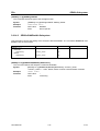
3 Remote Control .......................................................................................................................... 3.1
3.1
Introduction............................................................................................................................ 3.1
3.2
Brief Instructions................................................................................................................... 3.1
3.3
Switchover to Remote Control ............................................................................................. 3.2
3.3.1 Remote Control via IEC Bus ......................................................................................... 3.2
3.3.1.1 Setting the Device Address .............................................................................. 3.2
3.3.1.2 Indications during Remote Control ................................................................... 3.2
3.3.1.3 Return to Manual Operation ............................................................................. 3.3
3.3.2 Remote Control via RS-232-Interface ........................................................................... 3.3
3.3.2.1 Setting the Transmission Parameters .............................................................. 3.3
3.3.2.2 Indications during Remote Control ................................................................... 3.3
3.3.2.3 Return to Manual Operation ............................................................................. 3.4
3.3.3 Remote Control via RSIB Interface ............................................................................... 3.4
3.3.3.1
3.3.3.2
3.3.3.3
3.3.3.4
3.4
Windows Environment...................................................................................... 3.4
Unix Environment ............................................................................................. 3.5
Indications during Remote Control ................................................................... 3.5
Return to Manual Operation ............................................................................. 3.5
Messages ............................................................................................................................... 3.6
3.4.1 IEC/IEEE bus Interface Messages ................................................................................ 3.6
3.4.2 RSIB Interface Messages.............................................................................................. 3.6
3.4.3 Device Messages (Commands and Device Responses) .............................................. 3.7
3.5
Structure and Syntax of the Device Messages................................................................... 3.8
3.5.1 SCPI Introduction .......................................................................................................... 3.8
3.5.2 Structure of a Command ............................................................................................... 3.8
3.5.3 Structure of a Command Line ..................................................................................... 3.11
3.5.4 Responses to Queries................................................................................................. 3.11
3.5.5 Parameters.................................................................................................................. 3.12
3.5.6 Overview of Syntax Elements...................................................................................... 3.13
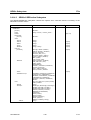
3.6
Description of Commands.................................................................................................. 3.14
3.6.1 Notation ....................................................................................................................... 3.14
3.6.2 Common Commands .................................................................................................. 3.17
3.6.3 CALCulate Subsystem ................................................................................................ 3.20
3.6.3.1
3.6.3.2
3.6.3.3
3.6.3.4
1127.8700.12
CALCulate:FILTer - Subsystem...................................................................... 3.20
CALCulate:FORMat Subsystem ..................................................................... 3.22
CALCulate:GDAPerture Subsystem ............................................................... 3.23
CALCulate:LIMit Subsystem........................................................................... 3.24
13
E-3
Contents
ZVx
3.6.3.5
3.6.3.6
3.6.3.7
3.6.3.8
3.6.3.9
CALCulate:MARKer Subsystem ..................................................................... 3.29
CALCulate:MATH Subsystem ........................................................................ 3.38
CALCulate:SMOothing Subsystem ................................................................ 3.39
CALCulate:TRANsform Subsystem ............................................................... 3.40
CALCulate:UNIT Subsystem .......................................................................... 3.43
3.6.4 DIAGnostic Subsystem ............................................................................................... 3.44
3.6.5 DISPlay Subsystem ..................................................................................................... 3.45
3.6.6 FORMat Subsystem .................................................................................................... 3.52
3.6.7 HCOPy Subsystem...................................................................................................... 3.55
3.6.8 INITiate Subsystem ..................................................................................................... 3.61
3.6.9 INPut Subsystem......................................................................................................... 3.62
3.6.10INSTrument Subsystem .............................................................................................. 3.63
3.6.11MMEMory Subsystem ................................................................................................. 3.64
3.6.12OUTPut Subsystem..................................................................................................... 3.72
3.6.13PROGram - Subsystem............................................................................................... 3.74
3.6.14SENSe Subsystem ...................................................................................................... 3.76
3.6.14.1
3.6.14.2
3.6.14.3
3.6.14.4
3.6.14.5
3.6.14.6
3.6.14.7
3.6.14.8
3.6.14.9
SENSe:AVERage Subsystem...................................................................... 3.76
SENSe:BANDwidth Subsystem ................................................................... 3.77
SENSe:CORRection Subsystem ................................................................. 3.78
SENSe:DETector - Subsystem .................................................................. 3.101
SENSe:FREQuency Subsystem ................................................................ 3.102
SENSe:FUNCtion Subsystem.................................................................... 3.107
SENSe:ROSCillator - Subsystem .............................................................. 3.109
SENSe:SEGMent Subsystem .................................................................... 3.110
SENSe:SWEep Subsystem ....................................................................... 3.112
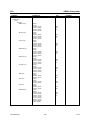
3.6.15SOURce Subsystem ................................................................................................. 3.114
3.6.16STATus Subsystem................................................................................................... 3.123
3.6.17SYSTem Subsystem ................................................................................................. 3.130
3.6.18TRACe Subsystem .................................................................................................... 3.140
3.6.19TRIGger-Subsystem.................................................................................................. 3.144
3.7
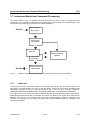
Instrument Model and Command Processing ................................................................ 3.146
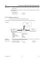
3.7.1 Input Unit ................................................................................................................... 3.146
3.7.2 Command Recognition.............................................................................................. 3.147
3.7.3 Data Set and Instrument Hardware........................................................................... 3.147
3.7.4 Status Reporting System........................................................................................... 3.147
3.7.5 Output Unit ................................................................................................................ 3.148
3.7.6 Command Sequence and Command Synchronization ............................................. 3.145
3.8
Status Reporting System .................................................................................................. 3.149
3.8.1 Structure of an SCPI Status Register........................................................................ 3.149
3.8.2 Overview of the Status Registers .............................................................................. 3.151
3.8.3 Description of the Status Registers ........................................................................... 3.152
1127.8700.12
14
E-3
ZVx
Contents
3.8.3.1
3.8.3.2
3.8.3.3
3.8.3.4
3.8.3.5
3.8.3.6
Status Byte (STB) and Service Request Enable Register (SRE) ................. 3.152
IST Flag and Parallel Poll Enable Register (PPE) ........................................ 3.153
Event-Status Register (ESR) and Event-Status-Enable Register (ESE)...... 3.153
STATus:OPERation Register ....................................................................... 3.154
STATus:QUEStionable-Register .................................................................. 3.155
STATus:QUEStionable:LIMit Register.......................................................... 3.156
3.8.4 Application of the Status Reporting System .............................................................. 3.157
3.8.4.1
3.8.4.2
3.8.4.3
3.8.4.4
3.8.4.5
Service Request, Making Use of the Hierarchy Structure ............................ 3.157
Serial Poll...................................................................................................... 3.157
Parallel Poll................................................................................................... 3.158
Query by Means of Commands.................................................................... 3.158
Error-Queue Query....................................................................................... 3.158
3.8.5 Reset Values of the Status Reporting System .......................................................... 3.159
3.9
Softkeys and Related IEC/IEEE BUS Commands........................................................... 3.160
3.9.1 SYSTEM Key Group.................................................................................................. 3.160
3.9.2 COPY Key Group ...................................................................................................... 3.166
3.9.3 MEMORY Key Group ................................................................................................ 3.167
3.9.4 STATUS Key Group .................................................................................................. 3.169
3.9.5 STIMULUS Key Group .............................................................................................. 3.170
3.9.6 SWEEP Key Group ................................................................................................... 3.170
3.9.7 MARKER Key Group ................................................................................................. 3.173
3.9.8 CHANNEL Key Group ............................................................................................... 3.176
3.9.9 RESPONSE Key Group ............................................................................................ 3.176
3.9.10CAL Key Group ......................................................................................................... 3.180
1127.8700.12
15
E-3
Contents
ZVx
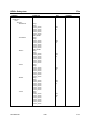
4 Maintenance and Troubleshooting .................................................................................... 4.1
4.1
Maintenance........................................................................................................................... 4.1
4.1.1 Mechanical Maintenance............................................................................................... 4.1
4.1.2 Electrical Maintenance .................................................................................................. 4.1
4.1.2.1
4.1.2.2
4.1.2.3
4.1.2.4
4.2
Testing the Generator Level ............................................................................. 4.1
Testing the Receiver Accuracy......................................................................... 4.1
Testing the Frequency Accuracy ...................................................................... 4.1
Verifying the Measuring Accuracy .................................................................... 4.1
Monitoring the Function ....................................................................................................... 4.2
4.2.1 Switch-on Test............................................................................................................... 4.2
4.2.2 Monitoring the Synthesizers and the Level Control ....................................................... 4.2
4.2.3 Synthesizer Error Messages ......................................................................................... 4.2
4.2.4 Error Message of Level Control..................................................................................... 4.2
4.2.5 Overload Displays ......................................................................................................... 4.2
4.3
Function Description of the Complete Instrument............................................................. 4.3
4.3.1 Description of the Analog Modules................................................................................ 4.3
4.3.1.1
4.3.1.2
4.3.1.3
4.3.1.4
4.3.1.5
4.3.1.6
4.3.1.7
Test Set ............................................................................................................ 4.3
Front End.......................................................................................................... 4.4
Converter .......................................................................................................... 4.4
Synthesizer ....................................................................................................... 4.4
Local ................................................................................................................. 4.5
Source .............................................................................................................. 4.5
Output Stage .................................................................................................... 4.5
4.3.2 Modules of the Digital Unit............................................................................................. 4.5
4.3.3 Processor Structure....................................................................................................... 4.6
4.3.3.1 Measurement Control Unit................................................................................ 4.6
4.4
Self test................................................................................................................................... 4.7
1127.8700.12
16
E-3
ZVx
Contents
Contents
5 Testing the Rated Specifications ........................................................................................ 5.1
5.1
Measuring Instruments and Accessories (ZVR, ZVRE, ZVRL).......................................... 5.1
5.2
Test Sequence (ZVR, ZVRE, ZVRL)...................................................................................... 5.2
5.2.1 Testing the Generator Specifications ............................................................................ 5.2
5.2.1.1
5.2.1.2
5.2.1.3
5.2.1.4
5.2.1.5
5.2.1.6
5.2.1.7
Frequency Accuracy......................................................................................... 5.2
Harmonics Suppression ................................................................................... 5.2
Spurious Suppression ...................................................................................... 5.3
Phase Noise ..................................................................................................... 5.4
Residual FM ..................................................................................................... 5.4
Level Accuracy ................................................................................................. 5.5
Level Linearity................................................................................................... 5.7
5.2.1.7.1 Matching to Output a1 .................................................................... 5.8
5.2.2 Testing the Receiver Specifications .............................................................................. 5.9
5.2.2.1
5.2.2.2
5.2.2.3
5.2.2.4
Absolute Accuracy............................................................................................ 5.9
Linearity .......................................................................................................... 5.10
Noise Level ..................................................................................................... 5.11
Matching Input b1 and Input b2 ...................................................................... 5.12
5.2.3 Testing the Test Set Specifications ............................................................................. 5.14
5.2.3.1
5.2.3.2
5.2.3.3
5.2.3.4
Matching to PORT1 and PORT2 .................................................................... 5.14
Directivity ........................................................................................................ 5.15
Testing the Attenuators .................................................................................. 5.16
Crosstalk......................................................................................................... 5.17
5.3
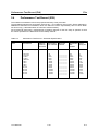
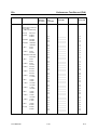
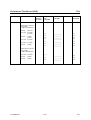
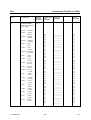
Performance Test Report (ZVR, ZVRE, ZVRL) .................................................................. 5.17
5.4
Measuring Instruments and Accessories (ZVC, ZVCE) ................................................... 5.52
5.5
Test Sequence (ZVC, ZVCE) ............................................................................................... 5.53
5.5.1 Testing the Generator Specifications .......................................................................... 5.53
5.5.1.1
5.5.1.2
5.5.1.3
5.5.1.4
5.5.1.5
5.5.1.6
5.5.1.7
5.5.1.8
Frequency Accuracy....................................................................................... 5.53
Harmonics Suppression ................................................................................. 5.53
Spurious Suppression .................................................................................... 5.54
Phase Noise ................................................................................................... 5.55
Residual FM ................................................................................................... 5.55
Level Accuracy ............................................................................................... 5.56
Level Linearity................................................................................................. 5.56
Matching to Output a1 .................................................................................... 5.57
5.5.2 Testing the Receiver Specifications ............................................................................ 5.58
5.5.2.1
5.5.2.2
5.5.2.3
5.5.2.4
1127.8700.12
Absolute Accuracy.......................................................................................... 5.58
Linearity .......................................................................................................... 5.59
Noise Level ..................................................................................................... 5.60
Matching Input b1 and Input b2 ...................................................................... 5.61
17
E-3
Contents
ZVx
5.5.3 Testing the Test Set Specifications ............................................................................. 5.63
5.5.3.1
5.5.3.2
5.5.3.3
5.5.3.4
5.6
Matching to PORT1 and PORT2 .................................................................... 5.63
Directivity ........................................................................................................ 5.63
Testing the Attenuators .................................................................................. 5.64
Crosstalk......................................................................................................... 5.65
Performance Test Report (ZVC, ZVCE) ............................................................................. 5.66
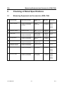
5 Checking of Rated Specifications ...................................................................................... 5.1
5.1
Measuring Equipment and Accessories (ZVM, ZVK) ......................................................... 5.1
5.2
Test Procedure (ZVM & ZVK)................................................................................................ 5.2
5.2.1 Checking the Generator Specifications ......................................................................... 5.2
5.2.1.1
5.2.1.2
5.2.1.3
5.2.1.4
5.2.1.5
5.2.1.6
5.2.1.7
Frequency Deviation......................................................................................... 5.2
Harmonics ........................................................................................................ 5.3
Spurious ........................................................................................................... 5.4
Phase Noise ..................................................................................................... 5.5
Residual FM ..................................................................................................... 5.6
Level Accuracy ................................................................................................. 5.7
Level Linearity................................................................................................... 5.8
5.2.2 Checking the Receiver Specifications ........................................................................... 5.9
5.2.2.1
5.2.2.2
5.2.2.3
5.2.2.4
Absolute Accuracy............................................................................................ 5.9
Linearity .......................................................................................................... 5.10
Noise Level ..................................................................................................... 5.11
Match Input b1 and Input b2........................................................................... 5.12
5.2.3 Checking the Test Set Specifications.......................................................................... 5.13
5.2.3.1
5.2.3.2
5.2.3.3
5.2.3.4
5.2.3.5
Match at PORT1 and PORT2......................................................................... 5.13
Matching Reference Channel Inputs R1 and R2 Channel IN ......................... 5.14
Raw Directivity ................................................................................................ 5.15
Checking the Attenuators ............................................................................... 5.16
Dynamic Range .............................................................................................. 5.17
5.3
Performance Test Record (ZVM)........................................................................................ 5.18
5.4
Performance Test Record (ZVK) ........................................................................................ 5.70
1127.8700.12
18
E-3
ZVx
Contents
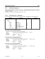
Annex A - Interfaces ......................................................................................................................A.1
A.1
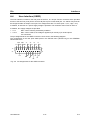
IEC Bus Interface (SCPI IEC625, SYSTEM BUS).................................................................A.1
Interface Characteristics..........................................................................................................A.1
Bus Lines .................................................................................................................................A.2
IEC Bus Messages ..................................................................................................................A.3
Interface Messages .................................................................................................................A.3
Instrument Messages ..............................................................................................................A.4
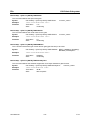
A.2
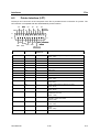
RS-232-C Interface (COM1, COM2) ......................................................................................A.5
Interface Characteristics..........................................................................................................A.5
Signal Lines .............................................................................................................................A.5
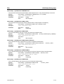
Transmission Parameters .......................................................................................................A.6
Interface Functions ..................................................................................................................A.7
Handshake ..............................................................................................................................A.7
A.3
RSIB Interface ...................................................................................................................A.9
Windows Environment.............................................................................................................A.9
Unix Environment ..................................................................................................................A.10
RSIB Interface Functions.......................................................................................................A.11
Variables ibsta, iberr, ibcntl .........................................................................................A.11
Overview of Interface Functions..................................................................................A.12
Description of Interface Functions...............................................................................A.13
A.4
User Interface (USER) .........................................................................................................A.21
A.5
Printer Interface (LPT).........................................................................................................A.22
A.6
Probe Connectors (PROBE 1, PROBE 2) ..........................................................................A.23
A.7
Reference Input (REF IN) ....................................................................................................A.23
A.8
Reference Output (REF OUT) .............................................................................................A.23
A.9
External Trigger Input (EXT TRIGGER) .............................................................................A.23
A.10 External Level Control Input (LEVEL)................................................................................A.23
A.11 DC Voltage Input for PORT 1 and PORT 2 (PORT BIAS 1 / 2) .........................................A.23
A.12 Connectors for Controlling an Ext. Gen. of the R&S Family SME / SMP and other .....A.24
A.13 External Reference Mixer Connector (a1 EXT OUT, a1 EXT IN)......................................A.24
A.14 External Keyboard (KEYBOARD) .......................................................................................A.24
A.15 Mouse Connector (MOUSE) ...............................................................................................A.25
A.16 Monitor Connectors (PC MONITOR, ANALYZER MONITOR) ..........................................A.25
1127.8700.12
19
E-3
Contents
ZVx
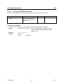
Annex B – List of Error Messages ...........................................................................................B.1
B.1
SCPI-Specific Error Messages .............................................................................................B.1
Annex C – List of Commands ....................................................................................................C.1
Annex D – Programming Examples ........................................................................................D.1
D.1
Including IEC-Bus Library for QuickBasic ..........................................................................D.1
D.2
Initialization and Default Status ...........................................................................................D.1
D.2.1 Initiate Controller ...........................................................................................................D.1
D.2.2 Initiate Instrument..........................................................................................................D.1
D.3
Transmission of Instrument Setting Commands ...............................................................D.2
D.4
Switchover to Manual Control..............................................................................................D.2
D.5
Reading out Instrument Settings .........................................................................................D.2
D.6
Positioning a Marker and Displaying Values ......................................................................D.2
D.7
Command synchronization ..................................................................................................D.3
D.8
Service Request.....................................................................................................................D.4
D.9
Programming via the RSIB Interface ...................................................................................D.6
D.9.1
D.9.2
D.9.3
Visual Basic ......................................................................................................D.6
Visual Basic for Applications (Winword and Excel) ..........................................D.8
C / C++ ...........................................................................................................D.10
Annex E - Emulations....................................................................................................................E.1
E.1
Mouse Control of Display Elements ....................................................................................E.1
E.2
Front Panel Keyboard Emulation.........................................................................................E.2
1127.8700.12
20
E-3
ZVx
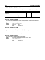
Figures
Figures
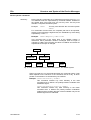
Fig. 3-1 Tree structure of the SCPI command systems: The SENSe system ...................................... 3.9
Fig. 3-2 Model of the instrument in the case of remote control by means of the IEC bus ................ 3.146
Fig. 3-3 The status register model .................................................................................................... 3.149
Fig. 3-4 Overview over the status registers ...................................................................................... 3.151
Fig. A-1 Pin assignment of IEC-Bus interface.......................................................................................A.1
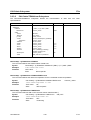
Fig. A-2 Pin assignment of the RS-232-C interface ..............................................................................A.5
Fig. A-3 Wiring of the data lines for software handshake .....................................................................A.7
Fig. A-4 Wiring of the data, control and acknowledge lines for hardware handshake ..........................A.8
Fig. A-5 Pin assignments for the USER connector .............................................................................A.21
Fig. A-6 Pin assignments for the LPT connector. ...............................................................................A.22
Fig. A-7 Pin assignments of the KEYBOARD connector. ...................................................................A.24
Fig. A-8 Pin assignments for the MOUSE connector. .........................................................................A.25
Fig. A-9 Pin assignments of the MONITOR connector. ......................................................................A.25
1127.8700.12
21
E-3
Tables
ZVx
Tables
Table 3-1 Synchronisation using *OPC *OPC? and *WAI................................................................. 3.148
Table 3-2 Meaning of the bits used in the status byte ....................................................................... 3.152
Table 3-3 Meaning of the bits used in the event status register ........................................................ 3.153
Table 3-4 Meaning of the bits used in the STATus.OPERation register............................................ 3.154
Table 3-5 Meaning of the bits used in the STATus:QUEStionable register....................................... 3.155
Table 3-6 Meaning of the bits used in the STATus:QUEStionable:LIMit register .............................. 3.156
Table 3-7 Resettting instrument functions ......................................................................................... 3.159
Table 4-1 Possible error messages ....................................................................................................... 4.2
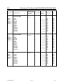
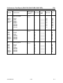
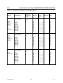
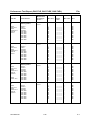
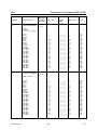
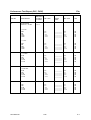
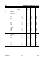
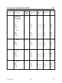
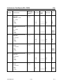
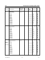
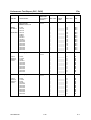
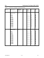
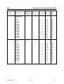
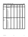
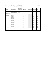
ZVR, ZVRE, ZVRL, ZVC, ZVCE
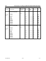
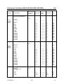
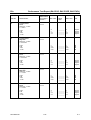
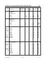
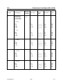
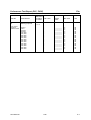
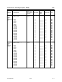
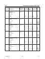
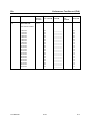
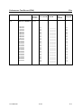
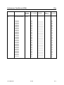
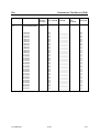
Table 5-1 Performance Test Report – Generator Specifications......................................................... 5.17
Table 5-2 Performance Test Report: Receiver specifications ............................................................. 5.31
Table 5-3 Performance Test Report: Test Set Specifications ............................................................. 5.41
Table 5-4 Performance Test Report: Crosstalk ................................................................................... 5.50
Table 5-5 Performance Test Report – Generator Specifications......................................................... 5.66
Table 5-6 Performance Test Report: Receiver Specifications............................................................ 5.73
Table 5-7 Performance Test Report: Test Set Specifications ............................................................. 5.78
Table 5-8 Performance Test Report: Crosstalk ................................................................................... 5.84
ZVK, ZVM
Table 5-1 Performance Test Record – Generator Specifications........................................................ 5.18
Table 5-2 Performance Test Record – Generator Specifications........................................................ 5.70
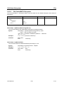
Table A-1 Interface functions .................................................................................................................A.3
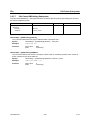
Table A-2 Universal Commands ............................................................................................................A.4
Table A-3 Addressed Commands ..........................................................................................................A.4
Table A-4 Control strings or control characters of the RS-232 interface ...............................................A.7
1127.8700.12
22
E-3
ZVx
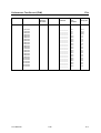
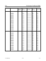
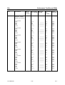
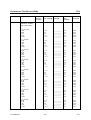
Index
Index
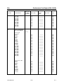
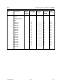
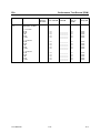
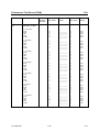
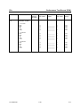
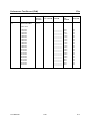
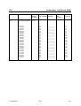
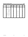
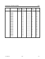
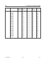
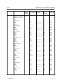
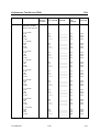
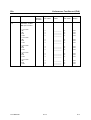
Note:
All softkeys are listed with their names. The page numbers 2.xxx refer to the detailed
description of the softkeys in chapter 2. Generally, the number of the page in chapter 3
containing the equivalent remote control command is given in addition.
A list of softkeys and equivalent remote control commands or command sequences is
given in section 3.9.
Annex C contains a list of all remote control commands.
APPLY CAL (TOSM)..........................................2.313, 3.93
APPLY CAL (TOSM, ZVRE) ..............................2.319, 3.93
APPLY CAL (TRANS AND REFL NORM, ZVR)
...........................................................................2.337, 3.93
APPLY CAL (TRANS AND REFL NORM, ZVRL)
...........................................................................2.340, 3.93
APPLY CAL (TRANS NORM, ZVR) ...................2.334, 3.93
APPLY CAL (TRANS NORM, ZVRL) .................2.338, 3.93
APPLY CAL(TNA) ........................................................ 3.93
ARBITRARY ....................................................2.199, 3.113
ARBITRARY (mixer measurements) ................2.123, 3.104
ARBITRARY GATE SHAPE...............................2.103, 3.21
ARBITRARY SIDELOBES .................................2.112, 3.42
ARBITRARY SYST FREQ (mixer measurements)
..............................................................2.124, 3.104, 3.121
ARBITRARY SYSTEM FREQUENCIES (selection table)
................................................................................... 2.123
ASCII .................................................................2.173, 3.53
ASCII file
create................................................................... 2.173
define output format ............................................. 2.173
ASCII FILES............................................................... 2.173
ATTEN ...............................................................2.312, 3.92
Attenuator .................................................................. 2.209
AUI connector .............................................................. 1.44
AUTO LENGTH (OFFSET) ................................2.373, 3.97
AUTO RECALL .......................................................... 2.179
AUTOKAL
indicate ................................................................ 2.148
AUTOKAL CONNECTED........................................... 2.148
AUTOKAL FUNDAM´TAL ............................................ 3.93
AUTOKAL FUNDAM´TAL (ZVRE)................................ 3.93
AUTOKAL FUNDAM´TAL (ZVRL) ......................2.332, 3.93
AUTOSCALE .....................................................2.273, 3.47
Auxiliary line editor ....................................................... 2.92
AVERAGE..........................................................2.212, 3.76
AVERAGE RESTART ........................................2.213, 3.76
Averaging................................................................... 2.212
Averaging factor ......................................................... 2.213
AVG (key) .................................................................. 2.212
AVG FACTOR....................................................2.213, 3.76
AVG TYPE SWEEP POINT ...............................2.213, 3.77
=
= MKR (key) ............................................................... 2.229
0
0...9 (key) .....................................................................2.81
1
1 Hz, ..., 10 kHz (softkeys)................................. 2.214, 3.77
1/S................................................. 2.219, 2.262, 3.31, 3.40
5
51, ..., 1601 (softkeys) ..................................... 2.199, 3.113
A
a1 INPUT POWER CAL ............................................. 2.364
a1, ... , b2 ........................................................ 2.253, 3.107
Abort
macro ................................................................... 2.182
Abscissa scaling
time domain transformation .................................. 2.113
ACCEPT POSITION........................................ 2.237, 2.240
Accessories
ZVC, ZVCE ............................................................5.52
ZVR, ZVRE, ZVRL ...................................................5.1
ACTIVATE KIT ........................................................... 2.347
ACTIVE XX STANDARDS (selection table) ................ 2.344
ACTIVE XX YY (menu table) ...................................... 2.350
ADD CONSTANT .............................................. 2.274, 3.50
Administrator identification............................................1.23
Admittance ................................................................. 2.261
absolute................................................................ 2.261
normalized ............................................................ 2.261
reference .............................................................. 2.261
serial .................................................................... 2.261
terminating............................................................ 2.261
ALL MARKER OFF............................................ 2.222, 3.30
Amplitude offset.......................................................... 2.372
Analyzer Monitor
Connector.............................................................. A.25
Aperture
group delay........................................................... 2.267
APPEND NEW .............................................................3.53
APPEND NEW ........................................................... 2.174
APPLY CAL................................. 2.307, 2.308, 2.310, 3.93
APPLY CAL (FULL ONE PORT)........................ 2.326, 3.93
APPLY CAL (FULL ONE PORT, ZVRL)............. 2.328, 3.93
APPLY CAL (ONE PATH, ZVR) ........................ 2.330, 3.93
APPLY CAL (ONE PATH, ZVRL) ...................... 2.332, 3.93
APPLY CAL (REFL NORM, ZVR)...................... 2.335, 3.93
APPLY CAL (REFL NORM, ZVRL).................... 2.339, 3.93
APPLY CAL (TNA) ..................................................... 2.312
APPLY CAL (TOM-X) ........................................ 2.315, 3.93
1127.8700.12
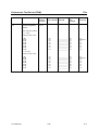
B
b1/a1, ... b2/a2 .................................................2.256, 3.107
BACK (key) .................................................................. 2.81
Bandfilter measurements............................................ 2.225
BANDFILTER MODE .........................................2.224, 3.33
BANDPASS .......................................................2.225, 3.33
Band-pass filter .......................................................... 2.225
BANDPASS LOWPASS.....................................2.108, 3.41
BANDSTOP .......................................................2.225, 3.33
Band-stop filter........................................................... 2.225
BNC connector............................................................. 1.43
BOTH PORTS....................................................2.324, 3.93
I.1
E-3
Index
ZVx
BOTH PORTS (REFL NORM, ZVR) .................. 2.335, 3.93
BRIGHTNESS ............................................................ 2.288
Broadband termination................................................ 2.304
COLORS.................................................................... 2.287
COLORS (selection table).......................................... 2.289
COM PORT 1........................................2.144, 3.136, 3.137
COM PORT 2........................................2.144, 3.136, 3.137
COM PORTS (selection table) ................................... 2.144
COM1/2 interface ....................................................... 2.144
Combined normalization ............................................. 2.336
Combined normalization (ZVRL)................................. 2.340
Commands
common ................................................................. 3.17
COMMENT CHANNEL 1, ..., 4...........................2.161, 3.59
Common commands .................................................... 3.17
COMP POINT INP/OUTP (compression point)
.........................................................................2.129, 3.107
COMPLEX .........................................................2.266, 3.22
COMPLEX CONVERS ................... 2.176, 2.261, 3.40, 3.54
COMPLEX MAGN/PHASE.................................2.232, 3.25
COMPRESS POINT.........................................2.127, 3.107
COMPRESS SOI TOI
............................. 2.126, 3.106, 3.107, 3.117, 3.118, 3.122
Compression point ..................................................... 2.126
measurement ....................................................... 2.127
CONFIG (key) ............................................................ 2.167
CONFIG DISPLAY ..................................................... 2.287
Configuration
save ..................................................................... 2.165
Connector family ........................................................ 2.300
CONNECTOR TYPE.................................................. 2.346
CONTINUOUS SWEEP .....................................2.205, 3.61
CONV GAIN |b1/a1| ................................................... 3.107
CONV GAIN |b2/a1| ................................................... 3.107
CONV GAIN b1/Pa1................................................... 2.256
CONV GAIN b2/Pa1................................................... 2.256
Conversion
display ................................................................... 2.50
Conversion gain ......................................................... 2.256
Copy
file ........................................................................ 2.168
COPY.................................................................2.168, 3.65
COPY LINE................................................................ 2.235
COPY MEM TRACE .................................................. 2.158
COPY SCREEN .................................................2.158, 3.58
COPY TABLE ....................................................2.158, 3.58
COPY TRACE....................................................2.158, 3.59
Correction
entry....................................................................... 2.90
Coupled channels ...................................................... 2.204
COUPLED CHANNELS .....................................2.204, 3.63
COUPLED MARKERS .......................................2.218, 3.30
CREATE INST FILE................................................... 2.351
Crosstalk errors.......................................................... 2.314
Cursor (key) ................................................................. 2.82
Cursor key
functions ................................................................ 2.82
CUTOFF FREQUENCY ............................................. 2.353
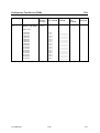
C
C............................................................. 2.221, 2.268, 3.22
CAL ................................................................... 2.176, 3.54
CAL (key group) ......................................................... 2.298
CAL (key) ................................................................... 2.298
CAL a1 POWER ................................... 2.209, 2.363, 3.116
CAL a2 POWER ................................... 2.209, 2.363, 3.116
CAL b1 INPUT POWER ............................................. 2.364
CAL b1 POWER ......................................................... 2.364
CAL EXT SRC1 POWER................................. 2.211, 3.116
CAL EXT SRC2 POWER................................. 2.211, 3.116
CAL INTERPOL................................................. 2.342, 3.92
CAL KITS .....................................................................3.93
CALEXT SRC 1 POWER............................................ 2.368
Calibration .................................................................. 2.298
full one-port .......................................................... 2.327
full two-port........................................................... 2.305
full two-port (ZVRE).............................................. 2.317
fundamental (ZVRL) ............................................. 2.332
interpolation.......................................................... 2.342
normalization (ZVR).............................................. 2.333
normalization (ZVRL)............................................ 2.338
offset .................................................................... 2.371
receiver power calibration..................................... 2.359
system error ......................................................... 2.299
unidirectional two-port (ZVR) ................................ 2.328
unidirectional two-port (ZVRL) .............................. 2.331
Calibration kit.............................................................. 2.343
Calibration mode......................................................... 2.300
Calibration procedure.................................................. 2.300
TNA...................................................................... 2.311
TOM ..................................................................... 2.305
TOM-X.................................................................. 2.314
TOSM................................................................... 2.312
TOSM (ZVRE) ...................................................... 2.318
TRL ...................................................................... 2.309
TRM ..................................................................... 2.307
Calibration standard.................................................... 2.301
Calibration test menu.................................................. 2.301
CENTER (key)...................................... 2.189, 3.103, 3.118
CENTER = MARKER ............................. 2.229, 2.243, 3.36
Center value ............................................................... 2.189
CENTER X ............................................. 2.236, 2.275, 3.26
CENTER Y ............................................. 2.236, 2.275, 3.26
CH1 - CH4 (keys) ....................................................... 2.245
CH1...CH4 (keys) .........................................................3.63
Channel
display .................................................................. 2.245
dual overlay ............................................................2.61
dual split .................................................................2.61
information..............................................................2.50
quad dual split ........................................................2.62
quad overlay...........................................................2.62
quad split................................................................2.63
representation ........................................................2.60
single......................................................................2.60
CHARTER ......................................................... 2.284, 3.46
Charter diagram............................................................2.72
CHIRP transformation................................................. 2.107
CHK VALUE SETTINGS (compression point)............. 2.129
CHK VALUE SETTINGS (intercept point) ................... 2.135
CLEAR ALL MESSAGES ........................................... 2.154
CLEAR MEM # ........................................................... 2.295
CLEAR MESSAGE..................................................... 2.154
CLR (key) .....................................................................2.81
COLOR ON / OFF .............................................. 2.161, 3.56
Colors ......................................................................... 2.287
1127.8700.12
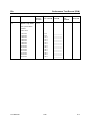
D
DATA ENTRY FIELD ................................................. 2.289
DATA ENTRY OPAQUE ............................................ 2.290
Data entry windows
mouse control ........................................................ 2.95
Data set
creation ................................................................ 2.177
partial................................................................... 2.172
recall .................................................................... 2.177
save ..................................................................... 2.169
DATA SET CLEAR.............................................2.171, 3.68
DATA SET CLEAR (RECALL).................................... 2.179
DATA SET CLEAR ALL ............................................... 3.69
DATA SET CLEAR ALL (RECALL) ............................ 2.179
DATA SET LIST......................................................... 2.170
I.2
E-3
ZVx
Index
DATA SET LIST (RECALL) ........................................ 2.179
DATA SET LIST / CONTENTS (RECALL) (selection table)
................................................................................... 2.179
DATA SET LIST / CONTENTS (SAVE) (selection table)
................................................................................... 2.170
DATA TO MEMORY ........................................ 2.292, 3.141
Date
input ..................................................................... 2.147
DATE............................................................... 2.147, 3.137
DB CARTESIAN ................................................ 2.278, 3.46
dB MAG AND PHASE ................... 2.174, 2.221, 3.31, 3.53
dB MAGNITUDE................................................ 2.220, 3.31
DB POLAR ........................................................ 2.282, 3.46
DC MEAS INPUT 1 .................................................... 2.264
DC MEAS INPUT 2 .................................................... 2.264
DEC SEP........................................................... 2.175, 3.53
Decimal separator....................................................... 2.175
DEF ARBITRARY (mixer measurements)
............................................................. 2.123, 3.104, 3.121
DEF CART SEGMENTS............................................. 2.279
DEF COMP PNT MEAS
............................. 2.128, 3.106, 3.107, 3.117, 3.118, 3.122
DEF MIXER MEAS.......................................... 2.119, 3.105
DEF POLAR SEGMENTS .......................................... 2.283
DEF SOI MEAS ..........................2.133, 3.106, 3.107, 3.122
DEF SRC 1 PCAL SWEEP......................................... 2.369
DEF SRC 2 PCAL SWEEP......................................... 2.369
DEF SWEEP SEGMENTS .............................. 2.194, 3.110
DEF TIME GATE ........................................................ 2.100
DEF TOI MEAS ..........................2.133, 3.106, 3.107, 3.122
DEF TRANSF TYPE................................................... 2.106
DEF TRIGGER ................................................ 2.200, 3.144
DEF X-AXIS ...................................................... 2.113, 3.42
DEFAULT CONFIG (RECALL) .......................... 2.181, 3.71
DEFAULT CONFIG (SAVE)............................... 2.172, 3.71
DEFAULT POSITION ................................................. 2.290
Default setup .............................................................. 2.183
DEFAULT STEP SIZE ..................................................2.95
DEFAULT VAL AND CHK SETTINGS OF SECOND /
THIRD ORDER INTERCEPT POINT MEASUREMENT
(table) ......................................................................... 2.135
DEFAULT VALUES AND CHECK SETTINGS OF
COMPRESSION POINT MEASUREMENT (table) ..... 2.129
DEFINE B’DFILTER .......................................... 2.225, 3.33
DEFINE CIRCLE ........................................................ 2.236
DEFINE MACRO ........................................................ 2.187
DEFINE MATH .................................................. 2.296, 3.38
DEFINE PAUSE ......................................................... 2.188
DEFINE RATIO ............................................... 2.255, 3.107
DEFINE RATIO (selection table) ................................ 2.255
DEFINE SECTIONS ................................................... 2.238
DEFINE S-PARAMETERS (selection table) ............... 2.250
DEL ACTIVE POINT................................................... 2.367
DEL ACTIVE POINT (EDIT POWER LOSS LIST) ...... 2.371
DEL ACTIVE SECTION.............................................. 2.240
DEL ACTIVE SEGMENT ...................... 2.197, 2.281, 3.111
DEL ALL POINTS....................................................... 2.367
DEL ALL POINTS (EDIT POWER LOSS LIST) .......... 2.370
DEL ALL SECTIONS .................................................. 2.240
DEL ALL SEGMENTS .......................... 2.197, 2.281, 3.111
Delay time .................................................................. 2.202
DELAY TIME (OFFSET).................................... 2.372, 3.96
Delete
file ........................................................................ 2.168
DELETE ................................................... 2.168, 3.66, 3.68
DELETE MACRO ....................................................... 2.188
DELTA (key)............................................................... 2.227
Delta marker .................................................................2.58
Delta markers ............................................................. 2.227
DELTA OFF....................................................... 2.228, 3.35
DEVICE SETTINGS (selection table) ......................... 2.162
1127.8700.12
Diagram
Cartesian .....................................................2.64, 2.278
Charter.........................................................2.72, 2.284
expand ................................................................. 2.286
inverted Smith ...................................................... 2.284
logarithmic ........................................................... 2.278
polar diagram ......................................................... 2.68
segmented ........................................................... 2.279
Smith ...........................................................2.71, 2.284
smoothing ............................................................ 2.294
DIAGRAM (key) ......................................................... 2.277
Directory
create................................................................... 2.168
rename................................................................. 2.168
Disable
operation................................................................ 2.93
DISABLE ALL ITEMS (RECALL)........................2.181, 3.71
DISABLE ALL ITEMS (SAVE)............................2.172, 3.71
Diskette
format .................................................................. 2.168
Display ....................................................................... 2.247
brightness ............................................................ 2.287
colors ................................................................... 2.287
conversion ............................................................. 2.50
formatting............................................................... 2.52
information on the diagram..................................... 2.50
marker info list ....................................................... 2.74
reference................................................................ 2.53
saturation ............................................................. 2.287
scale reference ...................................................... 2.77
scaling .......................................................... 2.52, 2.53
sweep position ....................................................... 2.57
sweep range .......................................................... 2.57
DISPLAY (key)........................................................... 2.285
Display channels ........................................................ 2.245
coupling ............................................................... 2.204
Display line.........................................................2.56, 2.231
DISPLAY OBJECTS (selection table) ........................ 2.287
Display windows .......................................................... 2.73
DISPLAYED DATA ............................................2.176, 3.54
Displays
mouse control ........................................................ 2.96
DIVIDED X AXIS................................................2.198, 3.46
Documentation ............................................... see hardcopy
DOMAIN TIME FREQ ......................................... 2.99, 3.20
DOMAIN TIME FREQUENCY ...................................... 3.40
DRIVE PORT PORT1/PORT2
............................... 2.254, 2.257, 2.258, 2.259, 2.260, 3.72
DUAL CHAN OVERLAY.....................................2.285, 3.45
DUAL CHAN SPLIT ...........................................2.286, 3.45
E
EDIT CAL KIT PATH (menu table) ............................. 2.352
EDIT COMMENT ...............................................2.171, 3.71
EDIT DIELECTRIC..................................................... 2.271
EDIT DIELECTRIC (OFFSET) ..................................... 3.97
EDIT DIELECTRIC (selection table)........................... 2.271
EDIT NAME ............................................................... 2.235
EDIT NAME (RECALL) ......................................2.178, 3.67
EDIT NAME (SAVE)...........................................2.170, 3.68
EDIT PATH ................................................................ 2.167
EDIT PATH (RECALL) .......................................2.178, 3.67
EDIT PATH (SAVE) ...........................................2.170, 3.65
EDIT POWER LOSS LIST ...............................2.370, 3.120
EDIT RTC TRIG TIME .....................................2.203, 3.144
EDIT SWEEP TIME .........................................2.203, 3.112
EDIT TIMER PERIOD ......................................2.202, 3.144
EDIT TITLE ................................................................ 2.291
Editing
parameter ..................................................... 2.88, 2.90
ELECTRICAL LENGTH.............................................. 2.269
I.3
E-3
Index
ZVx
ELECTRICAL LENGTH (OFFSET).................... 2.372, 3.97
Electrostatic discharge..................................................1.20
Enable
Front panel keys................................................... 2.182
ENABLE ALL ITEMS (RECALL) ........................ 2.181, 3.71
ENABLE ALL ITEMS (SAVE) ............................ 2.172, 3.71
ENABLE NEW OPTION ............................................. 2.149
Enhancement label .......................................................2.53
ARB...................................................................... 2.123
AVG ..................................................................... 2.212
CA? ...................................................................... 2.299
CAI ....................................................................... 2.299
CAL ...................................................................... 2.299
CMP ..................................................................... 2.127
EXT ...................................................................... 2.115
FST ...................................................................... 2.140
H=2 ...................................................................... 2.118
H=3 ...................................................................... 2.118
HLD...................................................................... 2.205
list of all ..................................................................2.53
MAT ..................................................................... 2.293
MIX....................................................................... 2.119
PC ........................................................................ 2.360
PC(x).................................................................... 2.360
PC? ...................................................................... 2.360
PCi ....................................................................... 2.360
PCo ...................................................................... 2.360
SMO..................................................................... 2.294
SOI....................................................................... 2.132
TIM.........................................................................2.99
TOI ....................................................................... 2.132
TRF RTC.............................................................. 2.202
TRG EXT.............................................................. 2.201
TRG LIN ............................................................... 2.201
TRG MAN............................................................. 2.202
TRG TIM .............................................................. 2.201
ENTER (key) ................................................................2.81
ENTER PASSWORD.................................................. 2.150
ENTER TEXT .................................................... 2.160, 3.58
Entry
abort .......................................................................2.81
activate.......................................................... 2.84, 2.87
correction ...............................................................2.90
terminate ................................................................2.81
ENTRY LINE1/LINE2.................................................. 2.232
Error messages, list .........................................see Annex B
Ethernet Adapter ..........................................................1.43
EXP (key) .....................................................................2.81
EXPAND............................................................ 2.286, 3.46
EXR SRC CONFIG.......................................... 3.133, 3.134
EXT LEVEL CONTROL .............................................. 2.148
EXT REF FREQUENCY .................................. 2.148, 3.109
EXT SOURCES CONFIG (selection table) ................. 2.120
EXT SRC 1 POWER ....................................... 2.210, 3.116
EXT SRC 1 SLOPE ......................................... 2.210, 3.116
EXT SRC 2 POWER ....................................... 2.211, 3.116
EXT SRC 2 POWER CAL........................................... 2.369
EXT SRC 2 SLOPE ......................................... 2.211, 3.116
EXT SRC CONFIG ..................................................... 3.132
EXT SRC CONFIG .......................................... 2.125, 2.369
EXT SRC CONFIG (mixer measurement)................... 2.120
EXT SRC1 (compression point) ....................... 2.131, 3.122
EXT SRC1 EXT SRC2 (SOI) ........................... 2.137, 3.122
EXT SRC1 EXT SRC2 (TOI) ........................... 2.137, 3.122
EXT SRC2 (compression point) ....................... 2.131, 3.122
Ext Trigger
input ...................................................................... A.23
EXTERNAL ....................................................... 2.115, 3.62
EXTERNAL (Trigger) ....................................... 2.201, 3.144
External generator ...................................................... 2.120
1127.8700.12
F
Fast Fourier transformation ........................................ 2.107
Fast Mode .................................................................. 2.140
FAST MODE ....................................................2.140, 3.101
FFT CHIRP ........................................................2.107, 3.41
File
copy ..................................................................... 2.168
delete................................................................... 2.168
rename................................................................. 2.168
sort....................................................................... 2.168
FILE MANAGEMENT (selection table) ....................... 2.167
Filter measurement
measurement example........................................... 2.17
Filtering
frequency range ................................................... 2.106
Firmware Options
enable .................................................................. 2.149
FIRMWARE OPTIONS .............................................. 2.153
FIRMWARE OPTIONS (selection table)..................... 2.149
FIRMWARE VERSIONS ............................................ 2.151
FIRMWARE VERSIONS (selection table) .................. 2.151
FIXED IF (mixer measurements) ......................2.121, 3.105
FIXED LO (mixer measurements) ....................2.121, 3.105
FIXED POS STIMULUS ............................................. 2.228
FIXED POS X VAL.............................................2.228, 3.35
FIXED POS Y VAL.............................................2.228, 3.35
FIXED RF (mixer measurements) ....................2.121, 3.105
Format
ASCII ................................................................... 2.173
FORMAT............................................................2.176, 3.54
FORMAT (key)........................................................... 2.265
FORMAT DISK ..................................................2.168, 3.66
Formatting.................................................................. 2.265
complex ............................................................... 2.266
display ................................................................... 2.52
imaginary part ...................................................... 2.267
magnitude ............................................................ 2.266
phase................................................................... 2.266
real part................................................................ 2.266
FORWARD ........................................................2.329, 3.93
Fourier transformation, fast ........................................ 2.107
FREE RUN................................................................. 2.201
FREQ OFFS OF 2ND SRC (SOI).....................2.134, 3.122
FREQ OFFS OF 2ND SRC (TOI).....................2.134, 3.122
Frequency
base..................................................................... 2.117
equation ............................................................... 2.124
fixed ..................................................................... 2.121
sweep .................................................................. 2.138
FREQUENCY........................................2.210, 2.290, 3.121
FREQUENCY APERTURE ................................2.268, 3.23
FREQUENCY CONVERS ................................2.117, 3.104
FREQUENCY SWEEP.....................................2.138, 3.107
Front panel
keyboard emulation.................................................. 2.2
FTP
operation................................................................ 1.54
FULL .......................................................................... 2.214
FULL ONE PORT...............................................2.324, 3.93
FULL PAGE .......................................................2.159, 3.60
FULL TWO PORT ...................................................... 2.305
FULL TWO PORT (ZVRE) ......................................... 2.317
Fuse............................................................................. 1.21
G
G/n (key) ...................................................................... 2.81
Gain factor ..................................................................... 2.2
Gate (time domain)....................................................... 2.99
GATE CENTER.............................. 2.105, 2.114, 3.21, 3.42
GATE SPAN .................................. 2.105, 2.114, 3.21, 3.42
I.4
E-3
ZVx
Index
GATE START ................................ 2.105, 2.114, 3.20, 3.41
GATE STOP.................................. 2.105, 2.114, 3.20, 3.42
Generator power calibration........................................ 2.355
GOTO POINT # (EDIT POWER LOSS LIST) ............. 2.371
GOTO POINT # (SENSOR CAL FACTOR) ................ 2.367
GOTO SECTION # ..................................................... 2.240
GOTO SEGMENT # ................................................... 2.281
GPIB ADDRESS.............................................. 2.142, 3.131
Graphic elements........................................................ 2.287
Grid ............................................................................ 2.282
harmonic .............................................................. 2.108
linear .................................................................... 2.193
logarithmic ............................................................ 2.193
user-defined ......................................................... 2.193
GRID .......................................................................... 2.282
GRID ANNOTATION .................................................. 2.282
Grid points
for time-domain transformation ............................. 2.108
Group delay ................................................................ 2.267
GROUP DELAY............................. 2.221, 2.267, 3.22, 3.31
Input reflection coefficient........................................... 2.248
INS NEW POINT..............................................2.367, 3.135
INS NEW POINT (EDIT POWER LOSS LIST) ........... 2.371
INS NEW SECTION...........................................2.240, 3.25
INS NEW SEGMENT ............................2.197, 2.281, 3.111
Insertion loss.................................................................. 2.2
INSTALL NEW KIT..................................................... 2.352
INSTALLED CAL KITS (menu table) .......................... 2.351
INSTALLED COMPONENTS (selection table) ........... 2.152
INSTALLED OPTIONS (selection table)..................... 2.152
Instrument model ....................................................... 3.146
INT SRC (compression point)..................................... 2.131
INT SRC EXT SRC1 (SOI)...............................2.137, 3.122
INT SRC EXT SRC1 (TOI) ...............................2.137, 3.122
INT SRC EXT SRC2 (SOI)...............................2.137, 3.122
INT SRC EXT SRC2 (TOI) ...............................2.137, 3.122
INT SRC1 (compression point)................................... 3.122
INTC POINT INP/OUTP (SOI)..........................2.134, 3.107
INTC POINT INP/OUTP (TOI)..........................2.134, 3.107
Intercept ..................................................................... 2.126
measurement (2nd/3rd order)................................. 2.132
Interface .......................................................... see Annex A
printer .................................................................... A.22
Interface configuration................................................ 2.141
Interfaces
IEC/IEEE bus........................................................... 3.1
RS-232-C................................................................. 3.1
Interpolation ............................................................... 2.342
INVERTED SMITH.............................................2.284, 3.46
ISOLATION YES/NO (TOSM).................................... 2.313
ISOLATION YES/NO (TOSM, ZVRE) ........................ 2.319
ITEMS TO RECALL (selection table) ......................... 2.181
ITEMS TO SAVE (selection table).............................. 2.172
H
Handshake protocol
hardware .............................................................. 2.145
software................................................................ 2.146
Hardcopy
comments............................................................. 2.160
copy ..................................................................... 2.155
format ................................................................... 2.163
output device ........................................................ 2.162
position................................................................. 2.159
screen .................................................................. 2.158
HARDCOPY DEVICE ........................................ 2.162, 3.68
Hardware .................................................................... 3.147
HARDWARE+OPTIONS............................................. 2.152
Harmonic Grid ............................................................ 2.108
Header line ...................................................................2.49
HOLD (key)...................................................................2.93
K
k/m (key) ...................................................................... 2.81
KEEP FREQ STEP WIDTH................................2.110, 3.41
KEEP STOP FREQ............................................2.110, 3.41
Key
COPY (hardcopy)................................................. 2.155
Key group
CHANNEL............................................................ 2.245
LINES .................................................................. 2.231
Keyboard
connector ............................................................... A.24
Keyboard, external
connection ............................................................. 1.25
K-FACTOR................................................................. 3.107
I
IEC/IEEE bus
address ................................................................ 2.142
commands and related softkeys ........................... 3.160
device messages......................................................3.7
interface .................................................................. A.1
interface messages ..................................................3.6
interfaces..................................................................3.1
set address...............................................................3.2
IF = BASE FREQ (mixer measurements)......... 2.120, 3.105
IF BANDWIDTH................................................. 2.214, 3.77
IF-Filter ....................................................................... 2.212
IMAGINARY .................................. 2.221, 2.267, 3.22, 3.31
IMMEDIATE ............................................................... 3.144
Impedance
serial .................................................................... 2.261
terminating............................................................ 2.261
IMPULSE STEP ................................................ 2.108, 3.41
INFO (Key) ................................................................. 2.151
Information
channel...................................................................2.50
test parameter ........................................................2.50
Information line .............................................................2.50
Input
a1 EXT IN.............................................................. A.24
BLANK .................................................................. A.24
Ext Trigger............................................................. A.23
LEVEL ................................................................... A.23
PORT BIAS 1 / 2 ................................................... A.23
REF IN .................................................................. A.23
INPUT.............................................................. 2.252, 3.107
1127.8700.12
L
L..............................................................2.221, 2.268, 3.22
LED message
REMOTE ................................................................. 3.2
Length
electrical .............................................................. 2.269
Length offset .............................................................. 2.372
Level error.................................................................. 2.298
Limit check ................................................................. 2.244
LIMIT CHECK ....................................................2.244, 3.24
Limit line.............................................................2.56, 2.233
cartesian diagram ................................................ 2.238
circle diagram....................................................... 2.236
copy ..................................................................... 2.235
move.................................................................... 2.242
select ................................................................... 2.234
LIMITS (key) .............................................................. 2.233
LIN CARTESIAN ................................................2.278, 3.46
LIN MAG AND PHASE................... 2.174, 2.221, 3.31, 3.53
LIN MAGNITUDE ...............................................2.220, 3.31
LIN POLAR ........................................................2.282, 3.46
I.5
E-3
Index
ZVx
LIN SWEEP.......................................... 2.193, 3.104, 3.113
Lin/Log
display ....................................................................2.51
LINE ................................................................ 2.201, 3.144
LINE 1 ............................................................... 2.310, 3.92
LINE 2 ............................................................... 2.310, 3.92
LINE SECTIONS (selection table) .............................. 2.239
Line style
selection of ........................................................... 2.164
LINE STYLE CHn ....................................................... 2.164
LINE STYLE MEM TRACE......................................... 2.164
LINES (key) ................................................................ 2.231
LIST INSTD KITS ....................................................... 2.351
LO = BASE FREQ (mixer measurements) ....... 2.120, 3.105
LO EXT SRC1/SRC2 (mixer measurements)... 2.120, 3.105
LOAD STATE ...............................................................3.67
LOCAL (key)............................................................... 2.182
LOCK ALL ....................................................................2.93
LOCK DATA .................................................................2.93
LOG CARTESIAN ............................................. 2.278, 3.46
LOG POLAR...................................................... 2.282, 3.46
LOG SWEEP........................................ 2.193, 3.104, 3.113
Login.............................................................................1.23
Login (NT controller) .....................................................1.23
Logo .................................................................. 2.53, 2.290
LOGO ......................................................................... 2.290
Logout ..........................................................................1.23
LOW FIRST SIDELOBE .................................... 2.111, 3.42
LOWER LEFT.................................................... 2.160, 3.60
LOWER RIGHT ................................................. 2.160, 3.60
LOWPASS DC S-PARAM .......................................... 2.110
LPT
interface ................................................................ A.22
MATCH P1 OPEN P2 .................................................. 3.92
MATCH PORT 1 .......................... 2.306, 2.308, 2.310, 3.92
MATCH PORT 1 (FULL ONE PORT) .................2.325, 3.92
MATCH PORT 1 (FULL ONE PORT, ZVRL) ......2.328, 3.92
MATCH PORT 1 (ONE PATH, ZVR) ..................2.330, 3.92
MATCH PORT 1 (ONE PATH, ZVRL) ................2.332, 3.92
MATCH PORT 1 (TOSM)...................................2.313, 3.92
MATCH PORT 1 (TOSM, ZVRE) .......................2.319, 3.92
MATCH PORT 2 .......................... 2.306, 2.308, 2.310, 3.92
MATCH PORT 2 (FULL ONE PORT) .................2.326, 3.92
MATCH PORT 2 (ONE PATH, ZVR) ..................2.330, 3.92
MATCH PORT 2 (TOSM)...................................2.313, 3.92
MATCH PORT 2 (TOSM, ZVRE) .......................2.319, 3.92
MATH.................................................................2.176, 3.54
MATH DATA/MEM ..................................................... 2.294
MATH DATA+MEM .................................................... 2.295
MATH DATA-MEM...........................................2.294, 2.295
MATH DATAxMEM .................................................... 2.295
MATH MEM/DATA ..................................................... 2.295
MATH USER DEF´D .................................................. 2.295
MAX = MARKER........................................................ 2.230
MAX MODE .......................................................2.224, 3.33
MAX VALUE ......................................................2.274, 3.49
MAXIMUM FLATNESS ......................................2.102, 3.21
MEAS (key)................................................................ 2.247
MEAS FREQ SUM/DIFF (SOI).........................2.134, 3.107
MEAS SIDEB LSB USB (TOI)..........................2.134, 3.107
Measured diagram
scaling ................................................................. 2.272
Measured quantity
conversion ........................................................... 2.261
diagram................................................................ 2.277
formatting............................................................. 2.265
manipulating mathematically ................................ 2.292
storing.................................................................. 2.292
Measurement
direct input signal ................................................. 2.252
ratio...................................................................... 2.255
save ..................................................................... 2.165
Measurement example
filter measurement ................................................. 2.17
transmission measurement ...................................... 2.2
Measuring diagram....................................................... 2.58
Measuring Instruments
ZVC, ZVCE ............................................................ 5.52
ZVR, ZVRE, ZVRL ................................................... 5.1
MECHANICAL LENGTH ............................................ 2.270
MECHANICAL LENGTH (OFFSET) ............................ 3.96
MECHANICAL LENGTH (OFFSET) ........................... 2.373
MEM 1, ... , MEM 8 .................................................... 2.294
Memory
battery-powered ..................................................... 1.22
configuration ........................................................ 2.167
Menu
arrows.................................................................... 2.79
call ......................................................................... 2.79
change keys........................................................... 2.80
Message windows........................................................ 2.73
Messages
acknowledgement .................................................. 2.76
MICROSOFT NET
operation................................................................ 1.48
MIDDLE = MARKER .................................................. 2.242
MIDDLE VAL/DELTA LIM .......................................... 2.241
MIN = MARKER ......................................................... 2.230
MIN MODE.........................................................2.224, 3.33
MIN VALUE........................................................2.274, 3.49
MIXER MEAS ..................................................2.119, 3.104
Mode
Delta marker ........................................................ 2.228
external measurement ......................................... 2.115
fast mode ............................................................. 2.140
M
M/µ (key) ......................................................................2.81
Macro
abort ..................................................................... 2.182
definition............................................................... 2.187
start ...................................................................... 2.185
MACRO 1...7 .............................................................. 2.186
MACRO TITLE ........................................................... 2.188
MAGNITUDE ..................................................... 2.266, 3.22
MAGNITUDE (OFFSET).................................... 2.372, 3.98
Maintenance ...................................................................4.1
MAKE DIRECTORY .......................................... 2.168, 3.67
MANUAL (trigger) ....................................................... 2.202
Manual control
switchover ............................................................ 2.182
MANUAL STEP SIZE ...................................................2.94
MANUAL TRIGGER ........................................ 2.202, 3.144
Marker ..........................................................................2.58
active.................................................................... 2.215
display of active value ............................................2.53
formatting ............................................................. 2.219
Lists........................................................................2.73
marker position..................................................... 2.215
marker value......................................................... 2.215
reference .............................................................. 2.227
representation ........................................................2.73
symbols ..................................................................2.73
MARKER (key group) ................................................. 2.215
MARKER 1 ............................................... 2.217, 3.30, 3.31
MARKER CONT/DISCR .................................... 2.222, 3.30
MARKER CONVERS.................................................. 2.218
MARKER DATA/MEM ....................................... 2.218, 3.31
MARKER INFO........................................................... 2.222
Marker info list ................................................... 2.74, 2.222
MATCH BOTH PORTS (TOM-X) ....................... 2.315, 3.92
MATCH BOTH PORTS (TOSM) ........................ 2.314, 3.92
MATCH BOTH PORTS (TOSM, ZVRE)............. 2.319, 3.92
1127.8700.12
I.6
E-3
ZVx
Index
frequency sweep .................................................. 2.138
frequency-converting measurements.................... 2.117
mixer measurements ............................................ 2.119
power sweep ........................................................ 2.139
reference mixer .................................................... 2.140
segmented sweep ................................................ 2.194
single point measurement..................................... 2.192
time sweep ........................................................... 2.139
MODE (key)..................................................................2.97
MODEL TYPE (selection table) ....................... 2.151, 2.152
MODIFY CAL KIT ....................................................... 2.343
MODIFY STANDARDS...................................... 2.348, 3.95
MODIFY XX YY STANDARDS (selection table) ......... 2.348
Module
information on....................................................... 2.152
Monitor
connection..............................................................1.26
Mouse
connection..............................................................1.25
connector .............................................................. A.25
operation ................................................................2.95
Mouse control
display elements.......................................................1.1
MOVE LINE..................................................... 2.232, 2.242
OPEN PORT 2 (FULL ONE PORT)....................2.325, 3.92
OPEN PORT 2 (ONE PATH, ZVR) ....................2.330, 3.92
OPEN PORT 2 (REFL NORM, ZVR)..................2.335, 3.92
OPEN PORT 2 (TOSM) .....................................2.313, 3.92
OPEN PORT 2 (TOSM, ZVRE) ..........................2.318, 3.92
OPEN PORT 2 (TRANS AND REFL NORM, ZVR)
...........................................................................2.337, 3.92
OPERAND X (selection table) .................................... 2.296
Operating mode
time domain ........................................................... 2.99
Operational site ............................................................ 1.20
OPERATOR X (selection table).................................. 2.297
Option
external measurements, ZVR-B25 ....................... 2.115
frequency-converting measurements, ZVR-B4..... 2.117
FSE-B16 - Ethernet Adapter .................................. 1.43
nonlinear measurements, ZVR-B5 ....................... 2.126
reference mixer .................................................... 2.140
reference mixer, ZVR-B6 ..................................... 2.140
Time Domain Transformation, ZVR-B2 .................. 2.98
OPTIONS................................................................... 2.149
Output
a1 EXT OUT .......................................................... A.24
REF OUT ............................................................... A.23
TRIGGER .............................................................. A.24
Output reflection coefficient........................................ 2.249
Output unit ................................................................. 3.148
N
N 50 Ω ................................................................ 2.346, 3.93
N 50 Ω FEMALE..................................... 2.301, 2.302, 3.93
N 50 Ω MALE .................................................... 2.302, 3.93
N 75 Ω ................................................................ 2.346, 3.93
N 75 Ω FEMALE................................................ 2.302, 3.93
N 75 Ω MALE .................................................... 2.302, 3.93
network operating system
FTP ........................................................................1.54
MICROSOFT NET..................................................1.48
NOVELL NETWARE ..............................................1.48
TCP/IP ...................................................................1.53
NO PROFILING................................................. 2.110, 3.42
NORMAL (key) ........................................................... 2.215
NORMAL GATE ................................................ 2.102, 3.21
NORMAL PROFILE ........................................... 2.111, 3.42
NOVELL NETWARE
operation ................................................................1.48
NT controller .................................................................1.23
NUMBER OF POINTS..................................... 2.199, 3.113
NUMBER OF READINGS................................ 2.368, 3.120
NUMBER OF SWEEPS................................... 2.205, 3.112
NUMBER OF TABLE ROWS...................................... 2.198
P
PAE............................................................................ 2.264
PAGE DOWN (DATA SET LIST)................................ 2.171
PAGE DOWN (FILE MANAGEMENT)........................ 2.168
PAGE DOWN (RECALL)............................................ 2.179
PAGE UP (DATA SET LIST)...................................... 2.171
PAGE UP (FILE MANAGEMENT).............................. 2.168
PAGE UP (RECALL).................................................. 2.179
Parameter
editing ........................................................... 2.88, 2.90
selection ................................................................ 2.83
Parameters ................................................................ 2.204
coupled ................................................................ 2.204
Parasitic capacitance ................................................. 2.350
Parasitic inductance ................................................... 2.350
Password
Windows NT .......................................................... 1.23
Path ........................................................................... 2.167
PC 3.5................................................................2.346, 3.93
PC 3.5 FEMALE.................................................2.302, 3.93
PC 3.5 MALE .....................................................2.302, 3.93
PC 7...................................................................2.346, 3.93
PC Monitor
Connector .............................................................. A.25
PEAK TO PEAK.................................................2.228, 3.36
Performance Test Report
(ZVR, ZVRE, ZVRL)............................................... 5.17
ZVC, ZVCE ............................................................ 5.66
PERIODIC TIMER............................................2.201, 3.144
PHASE........................................... 2.220, 2.266, 3.22, 3.31
PHASE (OFFSET) .............................................2.372, 3.98
Phase delay ............................................................... 2.269
PHASE DELAY .......................................................... 2.269
Phase offset ............................................................... 2.372
PHASE UNWRAP ..............................................2.269, 3.22
Plotter
connection ............................................................. 1.28
POINTS/DEC ...................................................2.200, 3.113
Polar diagram............................................................... 2.68
PORT 1 ..............................................................2.324, 3.93
PORT 1 (REFL NORM, ZVR)..................................... 2.335
PORT 1 CONNECTOR ......................................2.301, 3.93
PORT 2 ..............................................................2.324, 3.93
O
OFFSET (key) ............................................................ 2.371
Offset quantities.......................................................... 2.371
ONE PATH TWO PORT ...............................................3.93
Open........................................................................... 2.303
OPEN BOTH PORTS ........................................ 2.315, 3.92
OPEN P1 MATCH P2 ........................................ 2.315, 3.92
OPEN PORT 1 .................................................. 2.306, 3.92
OPEN PORT 1 (FULL ONE PORT) ................... 2.325, 3.92
OPEN PORT 1 (FULL ONE PORT, ZVRL) ........ 2.327, 3.92
OPEN PORT 1 (ONE PATH, ZVR) .................... 2.330, 3.92
OPEN PORT 1 (ONE PATH, ZVRL) .................. 2.331, 3.92
OPEN PORT 1 (REFL NORM, ZVR) ................. 2.335, 3.92
OPEN PORT 1 (REFL NORM, ZVRL) ............... 2.339, 3.92
OPEN PORT 1 (TOSM)..................................... 2.313, 3.92
OPEN PORT 1 (TOSM, ZVRE) ......................... 2.318, 3.92
OPEN PORT 1 (TRANS AND REFL NORM, ZVR)
.......................................................................... 2.337, 3.92
OPEN PORT 1 (TRANS AND REFL NORM, ZVRL)
.......................................................................... 2.340, 3.92
OPEN PORT 2 .................................................. 2.306, 3.92
1127.8700.12
I.7
E-3
Index
ZVx
PORT 2 (REFL NORM, ZVR) ..................................... 2.335
PORT1/PORT2........................................................... 2.372
POWER........................................................... 2.208, 3.115
Power added efficiency............................................... 2.264
Power loss list ............................................................ 2.369
POWER LOSS LIST (selection table) ......................... 2.370
POWER MTR CONFIG ........................ 2.365, 3.132, 3.135
POWER MTR CONFIG (selection table)..................... 2.365
POWER MTR TYPE (selection table) ......................... 2.365
POWER SWEEP ............................................. 2.139, 3.107
.....................................................................................3.99
Preset ......................................................................... 2.183
PRESET (key) ............................................................ 3.139
Printer
connection.....................................................1.28, A.22
Probe Power
connector .............................................................. A.23
Processing of measured values ....................................2.22
REFLECT PORT 2..................................2.308, 2.310, 3.93
Reflection coefficient .................................................. 2.248
Reflection normalization (ZVR)................................... 2.334
Reflection normalization (ZVRL)................................. 2.339
Remote control.....................2.121, 3.1 see SCPI-standard
ABORt ................................................................... 3.20
CALCulate ............................................................. 3.20
DIAGnostic............................................................. 3.44
DISPlay.................................................................. 3.45
FORMat ................................................................. 3.52
HCOPy .................................................................. 3.55
indication.............................................................. 2.182
INITiate .................................................................. 3.61
INPut...................................................................... 3.62
INSTrument ........................................................... 3.63
instrument model ................................................. 3.146
MMEMory .............................................................. 3.64
OUTPut.................................................................. 3.72
SENSe................................................................... 3.76
set transmission parameters .................................... 3.3
SOURce............................................................... 3.114
STATus................................................................ 3.123
switching on ............................................................. 3.2
SYSTem .............................................................. 3.130
TRACe ................................................................. 3.140
TRIGger ............................................................... 3.144
Remote Control
PROGram .............................................................. 3.74
Rename
directory ............................................................... 2.168
file ........................................................................ 2.168
RENAME............................................................2.168, 3.67
REPEAT PREV CAL .................................................. 2.341
Reset
instrument ............................................................ 2.183
RESET COLORS ....................................................... 2.289
RESET OFFSETS...................................................... 2.372
RESPONSE (key group) ............................................ 2.247
RESTART (key) ......................................................... 2.206
RESTORE INSTD KITS ............................................. 2.351
RESUME CAL............................................................ 2.341
REVERSE..........................................................2.329, 3.93
RF = BASE FREQ (mixer measurements)........2.120, 3.105
RJ45 (star topology)..................................................... 1.44
RLC ELEMENTS........................................................ 2.221
Rohde & Schwarz logo ................................................. 2.53
Rollkey
functions ................................................................ 2.82
RS-232-C
interface ...................................................................A.5
Q
QUAD CHAN DUAL SPLIT................................ 2.286, 3.45
QUAD CHAN OVERLAY ................................... 2.286, 3.45
QUAD CHAN QUAD SPLIT ............................... 2.286, 3.45
Quality factor .............................................................. 2.226
QUALITY FACTOR............................................ 2.226, 3.34
R
Rack
installation ..............................................................1.21
RADIUS.................................................. 2.237, 2.276, 3.27
Rated specifications
generator (ZVC, ZVCE) ..........................................5.53
generator (ZVR)........................................................5.2
measuring instruments .................................... 5.1, 5.52
receiver (ZVC, ZVCE).............................................5.58
test sequence (ZVC, ZVCE) ...................................5.53
test sequence (ZVR, ZVRE, ZVRL) ..........................5.2
test set (ZVC, ZVCE)..............................................5.63
test set (ZVR, ZVRE, ZVRL)...................................5.14
testing ......................................................................5.1
.................................................................................5.9
...............................................................................5.65
...............................................................................5.17
RATIO .................................................. 2.255, 2.258, 3.107
REAL ............................................. 2.220, 2.266, 3.22, 3.31
REAL AND IMAGINARY......................... 2.174, 2.221, 3.31
REAL TIME CLOCK ........................................ 2.202, 3.144
Real-time clock ........................................................... 2.202
Recall
data set ................................................................ 2.177
RECALL (key)............................................................. 2.177
RECALL DATA SET (selection table) ......................... 2.178
Receiver power calibration.......................................... 2.356
RECORD ON/OFF...................................................... 2.187
Reduction factor (wave velocity) ................................. 2.270
REF VAL = MARKER ........................................ 2.230, 3.37
Reference
external ................................................................ 2.148
Reference admittance................................................. 2.261
Reference circle............................................................2.56
REFERENCE EXT/INT.................................... 2.148, 3.109
Reference line ................................................. 2 . 5 6 , 2.273
REFERENCE MIXER ................................................. 2.140
REFERENCE POSITION .................................. 2.273, 3.48
Reference value ......................................................... 2.273
REFERENCE VALUE........................................ 2.273, 3.48
REFL NORM (ZVR) ........................................... 2.334, 3.93
REFL NORM (ZVRL) ......................................... 2.339, 3.93
REFLECT PORT 1 ................................. 2.308, 2.309, 3.93
1127.8700.12
S
S .................................................... 2.219, 2.261, 3.31, 3.40
S11 REFL PORT1............................................2.248, 3.107
S12 TRANS REV .............................................2.249, 3.107
S21 TRANS FWD ............................................2.248, 3.107
S22 REFL PORT2............................................2.249, 3.107
SATURATION............................................................ 2.288
Save
configuration ........................................................ 2.165
data set................................................................ 2.169
measurement ....................................................... 2.165
SAVE (key) ................................................................ 2.169
SAVE DATA SET (selection table) ............................. 2.169
SCALE (key) .............................................................. 2.272
Scale Reference Fields ................................................ 2.77
SCALE/DIV ........................................................2.273, 3.48
Scaling ....................................................................... 2.273
abscissa................................................................. 2.65
automatic ............................................................. 2.273
circular ................................................................... 2.71
I.8
E-3
ZVx
Index
display ........................................................... 2.52, 2.53
ordinate ..................................................................2.66
radial ......................................................................2.69
reference value..................................................... 2.273
SCPI-standard ................................................................3.1
block data...............................................................3.13
boolean parameters................................................3.12
command line .........................................................3.11
commands................................................................3.8
device-independent commands ................................3.8
device-specific commands........................................3.9
introduction...............................................................3.8
key words ...............................................................3.10
numerical values ....................................................3.12
parameters .............................................................3.12
queries ...................................................................3.11
strings ....................................................................3.13
syntax elements .....................................................3.13
text parameters ......................................................3.13
SCPI-status register ................................................... 3.149
IST flag................................................................. 3.153
service request enable register............................. 3.152
status byte............................................................ 3.152
SCR. MODE ON/OFF...................................................3.46
SCR. SAVER ON OFF ............................................... 2.290
SCR. SAVER ON/OFF .................................................3.46
SCR. SAVER TIME ........................................... 2.290, 3.46
Screen ..........................................................................2.48
diagram area ..........................................................2.49
setup ......................................................................2.48
softkey area............................................................2.59
subdivision .............................................................2.60
SEARCH ................................................ 2.223, 2.225, 3.32
SEARCH ← NEXT............................................. 2.224, 3.32
SEARCH (key)............................................................ 2.223
SEARCH NEXT ................................................. 2.224, 3.32
SEARCH NEXT ................................................. 2.224, 3.32
SECOND HARMONIC..................................... 2.118, 3.104
SEG SWEEP................................................... 2.193, 3.104
Segment list (sweep) .................................................. 2.193
Segmentation ............................................................. 2.279
Cartesian.............................................................. 2.279
radial .................................................................... 2.283
SEGMENTED CARTESIAN............................... 2.278, 3.46
SEGMENTED POLAR....................................... 2.282, 3.46
SEL BAND (mixer measurements)................... 2.122, 3.106
SEL ITEMS TO COPY................................................ 2.158
SEL ITEMS TO RECALL ................................... 2.180, 3.69
SEL ITEMS TO SAVE ....................................... 2.172, 3.69
SELECT KIT.................................................................3.93
SELECT LINE............................................................. 2.234
SELECT MACRO ....................................................... 2.188
SELECT OBJECT ...................................................... 2.288
SELECT OBJECT (selection table)............................. 2.288
SELECT QUADRANT........................................ 2.159, 3.60
SELECT UNIT ............................................................ 2.253
SELECT UNIT (selection table) .................................. 2.253
Selection table
position................................................................. 2.289
SELFTEST (selection table) ....................................... 2.153
SENSOR A CAL FACTOR.......................................... 2.367
SENSOR A CAL FACTOR LIST (selection table) ....... 2.367
SENSOR B CAL FACTOR LIST (selection table) ....... 2.367
SENSOR LABEL ........................................................ 2.368
Serial admittance ........................................................ 2.261
Serial impedance ........................................................ 2.261
Serial interface
configuration......................................................... 2.144
SERVICE.................................................................... 2.150
Service request..................................................... see SRQ
SET COLOR............................................................... 2.289
SET DIELECTRIC ...................................................... 2.270
1127.8700.12
SET DIELECTRIC (OFFSET).............................2.373, 3.97
SET DIELECTRIC (selection table)............................ 2.270
SET FREQS LOWPASS ............................................ 2.109
SET PATH ................................................................... 3.65
SET PATH A
\ (RECALL) .......................................................... 2.179
\ (SAVE)............................................................... 2.170
\ (SETTING)......................................................... 2.159
SET PATH C
\... (RECALL) ....................................................... 2.179
\... (SAVE)............................................................ 2.170
...\ (SETTING)...................................................... 2.159
SET Z0.............................................................2.259, 2.262
SETTINGS DEVICE 1, 2 ...........................3.56, 3.68, 3.131
Settling time ............................................................... 2.129
SETTLING TIME (compression point) ..............2.129, 3.106
SETTLING TIME (SOI) ....................................2.134, 3.106
SETTLING TIME (TOI).....................................2.134, 3.106
Setup ......................................................................... 2.141
general................................................................. 2.142
SETUP (key) .............................................................. 2.141
SEXLESS USR CONN 1....................................2.347, 3.93
SEXLESS USR CONN1............................................. 2.302
SHAPE FACT 60 dB / 3 dB ................................2.226, 3.34
SHAPE FACT 60 dB / 6 dB ................................2.226, 3.34
Shape factor............................................................... 2.226
SHORT PORT 1.................................................2.313, 3.92
SHORT PORT 1 (FULL ONE PORT) .................2.325, 3.92
SHORT PORT 1 (FULL ONE PORT, ZVRL) ......2.327, 3.92
SHORT PORT 1 (ONE PATH, ZVR) ..................2.330, 3.92
SHORT PORT 1 (ONE PATH, ZVRL) ................2.332, 3.92
SHORT PORT 1 (TOSM, ZVRE)........................2.319, 3.92
SHORT PORT 2.................................................2.313, 3.92
SHORT PORT 2 (FULL ONE PORT) .................2.325, 3.92
SHORT PORT 2 (ONE PATH, ZVR) ..................2.330, 3.92
SHORT PORT 2 (TOSM, ZVRE)........................2.319, 3.92
SHOW DATA ............................................................. 2.293
SHOW LINE.....................................................2.232, 2.244
SHOW MATH.....................................................2.293, 3.38
SHOW MEM ......................................................2.293, 3.51
Sign (key)..................................................................... 2.81
SINGLE CHANNEL ............................................2.285, 3.45
SINGLE POINT ................................................2.192, 3.104
Single point measurement.......................................... 2.192
SINGLE SWEEP................................................2.205, 3.61
SIZE X ....................................................................... 2.275
SIZE Y ....................................................................... 2.276
SLIDE 1 (FULL ONE PORT, ZVRL) ........................... 2.328
SLIDE PORT 1............................. 2.307, 2.308, 2.313, 3.92
SLIDE PORT 1 (FULL ONE PORT) ...................2.326, 3.92
SLIDE PORT 1 (ONE PATH, ZVR) ....................2.330, 3.92
SLIDE PORT 1 (ONE PATH, ZVRL) ..................2.332, 3.92
SLIDE PORT 1 (TOSM, ZVRE)..........................2.319, 3.92
SLIDE PORT 2............................. 2.307, 2.308, 2.313, 3.92
SLIDE PORT 2 (FULL ONE PORT) ...................2.326, 3.92
SLIDE PORT 2 (ONE PATH, ZVR) ....................2.330, 3.92
SLIDE PORT 2 (TOSM, ZVRE)..........................2.319, 3.92
Sliding load ................................................................ 2.303
SLOPE.............................................................2.208, 3.116
Slope factor................................................................ 2.208
SLOPE POS/NEG............................................2.202, 3.145
SMA ...................................................................2.346, 3.93
SMA FEMALE....................................................2.302, 3.93
SMA MALE ........................................................2.302, 3.93
SMITH................................................................2.284, 3.46
Smith chart................................................................. 2.284
inverted .................................................................. 2.72
Smoothing.................................................................. 2.294
SMOOTHING .....................................................2.294, 3.39
SMOOTHING APERTURE.................................2.294, 3.39
SMOOTHING function................................................ 2.176
I.9
E-3
Index
ZVx
Softkey
ENABLE DEV1 / DEV2......................................... 2.163
GENERAL SETUP ............................................... 2.142
MONITOR CONNECTED ..................................... 2.147
SETTINGS DEVICE 1/2 ....................................... 2.162
Softkey
display ....................................................................2.59
EXT SRC CONFIG ............................................... 2.130
IEC/IEEE bus .........................................................2.59
menu ......................................................................2.59
related IEC/IEEE-bus commands ......................... 3.160
Softkey TRANS NORM (ZVRL) .................................. 2.338
SOI .................................................................. 2.132, 3.107
SORT MODE.............................................................. 2.168
SOURCE (key) ........................................................... 2.207
Span ........................................................................... 2.189
SPAN (key)...................................................... 3.103, 3.119
SPAN (key)................................................................. 2.189
SPAN = MARKER ...................................................... 2.230
SRC POWER MAX LIMIT (compression point)
............................................................. 2.128, 3.117, 3.118
SRC POWER MAX LIMIT (SOI) ................................. 2.133
SRC POWER MAX LIMIT (TOI) ................................. 2.133
SRC POWER MIN LIMIT (compression point)
............................................................. 2.128, 3.117, 3.118
SRC POWER MIN LIMIT (SOI) .................................. 2.133
SRC POWER MIN LIMIT (TOI)................................... 2.133
SRQ
indication .............................................................. 2.182
Stability factor............................................................. 2.263
Standby ........................................................................1.21
Standing wave ratio .................................................... 2.267
START (key)................................ 2.189, 3.57, 3.103, 3.119
START = MARKER ........................................... 2.229, 3.36
START AUTOKAL ...................................................... 2.321
START NEW CAL ...................................................... 2.300
START NEW POWER CAL ........................................ 3.116
START POWER CAL ................................................. 2.355
Start value .................................................................. 2.189
Start-Up ........................................................................1.20
Status registers........................................................... 3.151
Status reporting service request ................................. 3.157
Status reporting system .............................................. 3.147
error queue query ................................................. 3.158
parallel poll ........................................................... 3.158
queries ................................................................. 3.158
reset values.......................................................... 3.159
serial poll .............................................................. 3.157
use ....................................................................... 3.157
STEEP EDGES ................................................. 2.101, 3.21
STEEP FALLOFF .............................................. 2.111, 3.42
STEEPEST EDGES .......................................... 2.100, 3.21
STEP (key) ...................................................................2.94
STEP APERTURE............................................. 2.267, 3.23
STEP ATT a1 .................................................... 2.209, 3.72
STEP ATT a1 AND a2 ....................................... 2.209, 3.72
STEP ATT a2 .................................................... 2.210, 3.72
STEP ATT b1 .................................................... 2.210, 3.62
STEP ATT b2 .................................................... 2.210, 3.62
STEP SIZE ...................................................... 2.200, 3.113
Stepsize
settings...................................................................2.94
STIMULUS (key group) .............................................. 2.189
STOP (key)........................................... 2.189, 3.103, 3.119
STOP = MARKER ............................................. 2.229, 3.36
Stop value .................................................................. 2.189
SUPER COMPACT .................................................... 2.174
SUPERCOMPACT .......................................................3.53
Sweep
indikator..................................................................2.57
SWEEP (key group) ................................................... 2.191
SWEEP (key) ............................................................. 2.191
1127.8700.12
SWEEP DIR FWD/REV ...................................2.205, 3.113
Sweep direction.......................................................... 2.205
Sweep line ................................................................... 2.57
Sweep modes ............................................................ 2.138
Sweep segments........................................................ 2.194
SWEEP SEGMENTS (selection table) ....................... 2.195
SWEEP START/HOLD .............................................. 2.205
Sweep time ................................................................ 2.203
automatic setting.................................................. 2.203
manual setting...................................................... 2.203
SWEEP TIME AUTO/MAN...............................2.203, 3.112
SWEEP TYPE..................................................2.138, 3.107
switch-on test ................................................................. 4.2
SWR .............................................. 2.221, 2.267, 3.22, 3.31
SYMMETRIC NETWORK .......................................... 2.311
SYSTEM (key group) ................................................... 2.97
System error .............................................................. 2.298
System error calibration ............................................. 2.299
System messages..............................................2.76, 2.153
SYSTEM MESSAGES ............................................... 2.153
System-error correction.............................................. 2.213
T
Table
operation................................................................ 2.85
scrolling ................................................................. 2.87
TAKE CAL SWEEP..........................................2.368, 3.120
TARGET MODE........................................2.224, 3.33, 3.34
Target search mode ................................................... 2.224
TCP/IP
operation................................................................ 1.53
Terminating admittance .............................................. 2.261
Terminating impedance .............................................. 2.261
Test parameter
information ............................................................. 2.50
Test Sequence
ZVC, ZVCE ............................................................ 5.53
ZVR, ZVRE, ZVRL ................................................... 5.2
Testing the Rated Specifications .................................... 5.1
Thick Ethernet.............................................................. 1.44
Thin Ethernet ............................................................... 1.43
THIRD HARMONIC..........................................2.118, 3.104
THROUGH (ONE PATH, ZVR) ..........................2.330, 3.92
THROUGH (ONE PATH, ZVRL).........................2.332, 3.92
THROUGH (TNA)...............................................2.311, 3.92
THROUGH (TOM)..............................................2.306, 3.92
THROUGH (TOM-X) ..........................................2.314, 3.92
THROUGH (TOSM) ...........................................2.313, 3.92
THROUGH (TOSM, ZVRE) ................................2.318, 3.92
THROUGH (TRANS AND REFL NORM, ZVR) ..2.337, 3.92
THROUGH (TRANS AND REFL NORM, ZVRL) 2.340, 3.92
THROUGH (TRANS NORM, ZVR).....................2.333, 3.92
THROUGH (TRANS NORM, ZVRL)...................2.338, 3.92
THROUGH (TRL) ...............................................2.309, 3.92
THROUGH (TRM) ..............................................2.308, 3.92
Time
input..................................................................... 2.147
TIME ................................................................2.147, 3.139
Time domain ................................................................ 3.20
TIME DOMAIN ..........................................2.98, 2.176, 3.54
TIME GATE......................................................... 2.99, 3.20
Time sweep................................................................ 2.139
TIME SWEEP ..................................................2.139, 3.107
TINT........................................................................... 2.288
TITLE ......................................................................... 2.291
Title line .............................................................2.49, 2.291
TNA....................................................................2.311, 3.93
TOI...................................................................2.132, 3.107
Tolerance band .......................................................... 2.239
Tolerance circles ........................................................ 2.236
TOM...................................................................2.305, 3.93
I.10
E-3
ZVx
Index
TOM-X............................................................... 2.314, 3.93
TOSM ................................................................ 2.312, 3.93
TOSM (ZVRE) ................................................... 2.318, 3.93
TOUCHSTONE ................................................. 2.173, 3.53
Trace ............................................................................2.58
TRACE (key) .............................................................. 2.292
TRACE MATH function............................................... 2.176
Tracking...................................................................... 2.223
TRACKING ........................................................ 2.224, 3.32
TRANS AND REFL NORM (ZVR)...................... 2.336, 3.93
TRANS AND REFL NORM (ZVRL).................... 2.340, 3.93
TRANS FWD REFL P1 (ZVR) ........................... 2.337, 3.93
TRANS FWD REFL P21...............................................3.93
TRANS NORM (ZVR) ........................................ 2.333, 3.93
TRANS REV REFL P2 (ZVR) ..................................... 2.337
Transmission coefficient ............................................. 2.248
Transmission measurement
measurement example .............................................2.2
Transmission normalization (ZVR) .............................. 2.333
Transmission normalization (ZVRL) ............................ 2.338
TRC COLOR AUTO INC.................................... 2.161, 3.59
TRIGGER DELAY ........................................... 2.202, 3.145
Trigger mode .............................................................. 2.200
external ................................................................ 2.201
free-running measuement..................................... 2.201
internal ................................................................. 2.201
manual ................................................................. 2.202
TRIGGER SWEEP/POINT .............................. 2.202, 3.145
TRL ................................................................... 2.309, 3.93
TRM .................................................................. 2.307, 3.93
TWO PORT NORM ......................................................3.93
TWO PORT NORM (ZVR) .......................................... 2.337
Two-tone signal .......................................................... 2.126
Windows NT................................................................. 1.23
administrator .......................................................... 1.23
login ....................................................................... 1.23
password ............................................................... 1.23
X
X DB COMP POINT (compression point) .........2.129, 3.107
X GRID LIN/LOG..............................................2.198, 3.113
X OFFSET ................................................................. 2.243
X POSITION .............................................................. 2.290
x1 (key) ........................................................................ 2.81
X-AXIS DISTANCE ............................................2.113, 3.42
X-AXIS DISTANCE/2 .........................................2.114, 3.42
X-AXIS TIME......................................................2.113, 3.42
Y
Y .................................................... 2.219, 2.262, 3.31, 3.40
Y GRID DB................................................................. 2.281
Y GRID LIN ................................................................ 2.281
Y GRID LOG .............................................................. 2.281
Y OFFSET ................................................................. 2.243
Y POSITION .............................................................. 2.290
Y SEGMENTS (selection table).................................. 2.280
Y/Y0 ............................................... 2.219, 2.262, 3.31, 3.40
Z
Z .................................................... 2.219, 2.262, 3.31, 3.40
Z/Z0 ............................................... 2.219, 2.262, 3.31, 3.40
ZERO DELAY AT MARKER....................................... 2.230
Zoom.......................................................................... 2.275
ZOOM ..............................................................2.275, 2.276
∆
U
∆ REF = FIXED POS .........................................2.228, 3.35
∆ REF = MARKER 1 ..........................................2.228, 3.35
UNCAL .........................................................................3.98
UNINSTALL KITS....................................................... 2.352
Unit (key) ......................................................................2.81
UNLOCK ......................................................................2.93
UPDATE MESSAGES ................................................ 2.154
UPPER LEFT .................................................... 2.160, 3.60
UPPER LIM/LOWER LIM .................................. 2.241, 3.26
UPPER RIGHT .................................................. 2.160, 3.60
USE CURSOR................................................. 2.237, 2.240
USE LINE STYLE....................................................... 2.164
USE MARKER...................................... 2.237, 2.241, 2.242
USE MIN STEP WIDTH..................................... 2.110, 3.41
USE POWER LOSS LIST................................ 2.369, 3.121
USE SENSOR A/B .......................................... 2.368, 3.134
User
interface ................................................................ A.21
USER (key) ................................................................ 2.185
USER CONN IMPEDANCE ........................................ 2.354
USER CONN NAME................................................... 2.354
USER DEF´D S-PARAMS .......................................... 2.250
User port
configuration......................................................... 2.143
USER PORT A ......................................... 2.143, 3.62, 3.73
USER PORT B ......................................... 2.143, 3.62, 3.73
USERPORTS (selection table) ................................... 2.143
USR CONN 2 .................................................... 2.347, 3.93
USR CONN 2 FEMALE .............................................. 2.302
USR CONN 2 MALE................................................... 2.302
µ
µ1-FACTOR ............................................................... 3.107
µ2-FACTOR ............................................................... 3.107
V
VIEW ACTIVE STD .................................................... 2.350
W
WAVEGUIDE ............................................................. 2.353
WIDTH............................................................... 2.226, 3.33
1127.8700.12
I.11
E-3
Important Hints before Operation:
For all instruments:
•
The directory C:\R_S\INSTR and its subdirectories are reserved for system software. Never
modify this directory in any way, otherwise the functioning of the instrument will be impaired.
•
Aborting a hardcopy is not possible when printout is in progress. Print jobs in the queue can be
deleted before printout has been started by pressing the HARDCOPY START key until the
message "Hardcopy in progress. Abort?" is displayed. The length of the queue is two jobs.
•
To avoid damage of electronic components of the DUT and the analyzer, the operational site
must be protected against electrostatic discharge.
Windows NT
Caution:
The drivers and programs used under Windows NT are adapted to the measuring
instrument. In order to prevent the instrument functions from damage, the settings
should only be modified as described below. Existing software may only be
modified using update software released by Rohde&Schwarz. Additionally only
programs authorized by Rohde&Schwarz for use on the ZVx may be run on the
instrument.
Do not power down during booting. Such a switch-off may lead to corruption of
the hard disk files.
Removable Harddisk FSE-B18
When using the Removable Harddisk, FSE-B18, please observe the following:
•
Always keep your Removable Harddisk in the plastic case included in this package.
•
Do not drop your Removable Harddisk.
•
Do not expose it to moisture, to extreme temperatures, or to a strong magnetic field.
•
Do not squeeze the external cover of the Removable Harddisk.
•
Do not affix additional labels.
•
Do not remove the existing label or write anything on to it.
1043.0009.50
S.1
E-5
Patent Information
This product contains technology licensed by Marconi Instruments LTD. under US patents 4609881 and
4870384 and under corresponding patents in Germany and elsewhere.
Please note the safety instructions on the next sheet !
1043.0009.50
S.2
E-5
Before putting the product into operation for
the first time, make sure to read the following
Safety Instructions
Rohde & Schwarz makes every effort to keep the safety standard of its products up to date and to offer
its customers the highest possible degree of safety. Our products and the auxiliary equipment required
for them are designed and tested in accordance with the relevant safety standards. Compliance with
these standards is continuously monitored by our quality assurance system. This product has been
designed and tested in accordance with the EC Certificate of Conformity and has left the manufacturer’s
plant in a condition fully complying with safety standards. To maintain this condition and to ensure safe
operation, observe all instructions and warnings provided in this manual. If you have any questions
regarding these safety instructions, Rohde & Schwarz will be happy to answer them.
Furthermore, it is your responsibility to use the product in an appropriate manner. This product is
designed for use solely in industrial and laboratory environments or in the field and must not be used in
any way that may cause personal injury or property damage. You are responsible if the product is used
for an intention other than its designated purpose or in disregard of the manufacturer's instructions. The
manufacturer shall assume no responsibility for such use of the product.
The product is used for its designated purpose if it is used in accordance with its operating manual and
within its performance limits (see data sheet, documentation, the following safety instructions). Using
the products requires technical skills and knowledge of English. It is therefore essential that the
products be used exclusively by skilled and specialized staff or thoroughly trained personnel with the
required skills. If personal safety gear is required for using Rohde & Schwarz products, this will be
indicated at the appropriate place in the product documentation.
Symbols and safety labels
Observe
operating
instructions
Weight
indication for
units >18 kg
Supply
voltage
ON/OFF
1171.0000.42-02.00
Danger of
electric
shock
Standby
indication
Direct
current
(DC)
Warning!
Hot
surface
PE terminal
Alternating
current (AC)
Ground
Direct/alternating
current (DC/AC)
Ground
terminal
Attention!
Electrostatic
sensitive
devices
Device fully
protected by
double/reinforced
insulation
Sheet 1
Safety Instructions
Observing the safety instructions will help prevent personal injury or damage of any kind caused by
dangerous situations. Therefore, carefully read through and adhere to the following safety instructions
before putting the product into operation. It is also absolutely essential to observe the additional safety
instructions on personal safety that appear in other parts of the documentation. In these safety
instructions, the word "product" refers to all merchandise sold and distributed by Rohde & Schwarz,
including instruments, systems and all accessories.
Tags and their meaning
DANGER
This tag indicates a safety hazard with a high potential of risk for the
user that can result in death or serious injuries.
WARNING
This tag indicates a safety hazard with a medium potential of risk for the
user that can result in death or serious injuries.
CAUTION
This tag indicates a safety hazard with a low potential of risk for the user
that can result in slight or minor injuries.
ATTENTION
This tag indicates the possibility of incorrect use that can cause damage
to the product.
NOTE
This tag indicates a situation where the user should pay special attention
to operating the product but which does not lead to damage.
These tags are in accordance with the standard definition for civil applications in the European
Economic Area. Definitions that deviate from the standard definition may also exist. It is therefore
essential to make sure that the tags described here are always used only in connection with the
associated documentation and the associated product. The use of tags in connection with unassociated
products or unassociated documentation can result in misinterpretations and thus contribute to personal
injury or material damage.
Basic safety instructions
1. The product may be operated only under
the operating conditions and in the
positions specified by the manufacturer. Its
ventilation must not be obstructed during
operation. Unless otherwise specified, the
following requirements apply to
Rohde & Schwarz products:
prescribed operating position is always with
the housing floor facing down, IP protection
2X, pollution severity 2, overvoltage
category 2, use only in enclosed spaces,
max. operation altitude max. 2000 m.
Unless specified otherwise in the data
sheet, a tolerance of ±10% shall apply to
the nominal voltage and of ±5% to the
nominal frequency.
2. Applicable local or national safety
regulations and rules for the prevention of
accidents must be observed in all work
performed. The product may be opened
only by authorized, specially trained
personnel. Prior to performing any work on
the product or opening the product, the
1171.0000.42-02.00
product must be disconnected from the
supply network. Any adjustments,
replacements of parts, maintenance or
repair must be carried out only by technical
personnel authorized by Rohde & Schwarz.
Only original parts may be used for
replacing parts relevant to safety (e.g.
power switches, power transformers,
fuses). A safety test must always be
performed after parts relevant to safety
have been replaced (visual inspection, PE
conductor test, insulation resistance
measurement, leakage current
measurement, functional test).
3. As with all industrially manufactured goods,
the use of substances that induce an
allergic reaction (allergens, e.g. nickel)
such as aluminum cannot be generally
excluded. If you develop an allergic
reaction (such as a skin rash, frequent
sneezing, red eyes or respiratory
difficulties), consult a physician immediately
to determine the cause.
Sheet 2
Safety Instructions
4. If products/components are mechanically
and/or thermically processed in a manner
that goes beyond their intended use,
hazardous substances (heavy-metal dust
such as lead, beryllium, nickel) may be
released. For this reason, the product may
only be disassembled, e.g. for disposal
purposes, by specially trained personnel.
Improper disassembly may be hazardous to
your health. National waste disposal
regulations must be observed.
5. If handling the product yields hazardous
substances or fuels that must be disposed
of in a special way, e.g. coolants or engine
oils that must be replenished regularly, the
safety instructions of the manufacturer of
the hazardous substances or fuels and the
applicable regional waste disposal
regulations must be observed. Also
observe the relevant safety instructions in
the product documentation.
6. Depending on the function, certain products
such as RF radio equipment can produce
an elevated level of electromagnetic
radiation. Considering that unborn life
requires increased protection, pregnant
women should be protected by appropriate
measures. Persons with pacemakers may
also be endangered by electromagnetic
radiation. The employer is required to
assess workplaces where there is a special
risk of exposure to radiation and, if
necessary, take measures to avert the
danger.
7. Operating the products requires special
training and intense concentration. Make
certain that persons who use the products
are physically, mentally and emotionally fit
enough to handle operating the products;
otherwise injuries or material damage may
occur. It is the responsibility of the
employer to select suitable personnel for
operating the products.
8. Prior to switching on the product, it must be
ensured that the nominal voltage setting on
the product matches the nominal voltage of
the AC supply network. If a different voltage
is to be set, the power fuse of the product
may have to be changed accordingly.
9. In the case of products of safety class I with
movable power cord and connector,
operation is permitted only on sockets with
earthing contact and protective earth
connection.
1171.0000.42-02.00
10. Intentionally breaking the protective earth
connection either in the feed line or in the
product itself is not permitted. Doing so can
result in the danger of an electric shock
from the product. If extension cords or
connector strips are implemented, they
must be checked on a regular basis to
ensure that they are safe to use.
11. If the product has no power switch for
disconnection from the AC supply, the plug
of the connecting cable is regarded as the
disconnecting device. In such cases, it
must be ensured that the power plug is
easily reachable and accessible at all times
(length of connecting cable approx. 2 m).
Functional or electronic switches are not
suitable for providing disconnection from
the AC supply. If products without power
switches are integrated in racks or systems,
a disconnecting device must be provided at
the system level.
12. Never use the product if the power cable is
damaged. By taking appropriate safety
measures and carefully laying the power
cable, ensure that the cable cannot be
damaged and that no one can be hurt by
e.g. tripping over the cable or suffering an
electric shock.
13. The product may be operated only from
TN/TT supply networks fused with max.
16 A.
14. Do not insert the plug into sockets that are
dusty or dirty. Insert the plug firmly and all
the way into the socket. Otherwise this can
result in sparks, fire and/or injuries.
15. Do not overload any sockets, extension
cords or connector strips; doing so can
cause fire or electric shocks.
16. For measurements in circuits with voltages
Vrms > 30 V, suitable measures (e.g.
appropriate measuring equipment, fusing,
current limiting, electrical separation,
insulation) should be taken to avoid any
hazards.
17. Ensure that the connections with
information technology equipment comply
with IEC 950/EN 60950.
18. Never remove the cover or part of the
housing while you are operating the
product. This will expose circuits and
components and can lead to injuries, fire or
damage to the product.
Sheet 3
Safety Instructions
19. If a product is to be permanently installed,
the connection between the PE terminal on
site and the product's PE conductor must
be made first before any other connection
is made. The product may be installed and
connected only by a skilled electrician.
20. For permanently installed equipment
without built-in fuses, circuit breakers or
similar protective devices, the supply circuit
must be fused in such a way that suitable
protection is provided for users and
products.
21. Do not insert any objects into the openings
in the housing that are not designed for this
purpose. Never pour any liquids onto or into
the housing. This can cause short circuits
inside the product and/or electric shocks,
fire or injuries.
22. Use suitable overvoltage protection to
ensure that no overvoltage (such as that
caused by a thunderstorm) can reach the
product. Otherwise the operating personnel
will be endangered by electric shocks.
23. Rohde & Schwarz products are not
protected against penetration of water,
unless otherwise specified (see also safety
instruction 1.). If this is not taken into
account, there exists the danger of electric
shock or damage to the product, which can
also lead to personal injury.
24. Never use the product under conditions in
which condensation has formed or can form
in or on the product, e.g. if the product was
moved from a cold to a warm environment.
25. Do not close any slots or openings on the
product, since they are necessary for
ventilation and prevent the product from
overheating. Do not place the product on
soft surfaces such as sofas or rugs or
inside a closed housing, unless this is well
ventilated.
26. Do not place the product on heatgenerating devices such as radiators or fan
heaters. The temperature of the
environment must not exceed the maximum
temperature specified in the data sheet.
27. Batteries and storage batteries must not be
exposed to high temperatures or fire. Keep
batteries and storage batteries away from
children. If batteries or storage batteries are
improperly replaced, this can cause an
explosion (warning: lithium cells). Replace
the battery or storage battery only with the
1171.0000.42-02.00
matching Rohde & Schwarz type (see
spare parts list). Batteries and storage
batteries are hazardous waste. Dispose of
them only in specially marked containers.
Observe local regulations regarding waste
disposal. Do not short-circuit batteries or
storage batteries.
28. Please be aware that in the event of a fire,
toxic substances (gases, liquids etc.) that
may be hazardous to your health may
escape from the product.
29. Please be aware of the weight of the
product. Be careful when moving it;
otherwise you may injure your back or other
parts of your body.
30. Do not place the product on surfaces,
vehicles, cabinets or tables that for reasons
of weight or stability are unsuitable for this
purpose. Always follow the manufacturer's
installation instructions when installing the
product and fastening it to objects or
structures (e.g. walls and shelves).
31. Handles on the products are designed
exclusively for personnel to hold or carry
the product. It is therefore not permissible
to use handles for fastening the product to
or on means of transport such as cranes,
fork lifts, wagons, etc. The user is
responsible for securely fastening the
products to or on the means of transport
and for observing the safety regulations of
the manufacturer of the means of transport.
Noncompliance can result in personal injury
or material damage.
32. If you use the product in a vehicle, it is the
sole responsibility of the driver to drive the
vehicle safely. Adequately secure the
product in the vehicle to prevent injuries or
other damage in the event of an accident.
Never use the product in a moving vehicle if
doing so could distract the driver of the
vehicle. The driver is always responsible for
the safety of the vehicle; the manufacturer
assumes no responsibility for accidents or
collisions.
33. If a laser product (e.g. a CD/DVD drive) is
integrated in a Rohde & Schwarz product,
do not use any other settings or functions
than those described in the documentation.
Otherwise this may be hazardous to your
health, since the laser beam can cause
irreversible damage to your eyes. Never try
to take such products apart, and never look
into the laser beam.
Sheet 4
Por favor lea imprescindiblemente antes de
la primera puesta en funcionamiento las
siguientes informaciones de seguridad
Informaciones de seguridad
Es el principio de Rohde & Schwarz de tener a sus productos siempre al día con los estandards de
seguridad y de ofrecer a sus clientes el máximo grado de seguridad. Nuestros productos y todos los
equipos adicionales son siempre fabricados y examinados según las normas de seguridad vigentes.
Nuestra sección de gestión de la seguridad de calidad controla constantemente que sean cumplidas
estas normas. Este producto ha sido fabricado y examinado según el comprobante de conformidad
adjunto según las normas de la CE y ha salido de nuestra planta en estado impecable según los
estandards técnicos de seguridad. Para poder preservar este estado y garantizar un funcionamiento
libre de peligros, deberá el usuario atenerse a todas las informaciones, informaciones de seguridad y
notas de alerta. Rohde&Schwarz está siempre a su disposición en caso de que tengan preguntas
referentes a estas informaciones de seguridad.
Además queda en la responsabilidad del usuario utilizar el producto en la forma debida. Este producto
solamente fue elaborado para ser utilizado en la indústria y el laboratorio o para fines de campo y de
ninguna manera deberá ser utilizado de modo que alguna persona/cosa pueda ser dañada. El uso del
producto fuera de sus fines definidos o despreciando las informaciones de seguridad del fabricante
queda en la responsabilidad del usuario. El fabricante no se hace en ninguna forma responsable de
consecuencias a causa del maluso del producto.
Se parte del uso correcto del producto para los fines definidos si el producto es utilizado dentro de las
instrucciones del correspondiente manual del uso y dentro del margen de rendimiento definido (ver
hoja de datos, documentación, informaciones de seguridad que siguen). El uso de los productos hace
necesarios conocimientos profundos y el conocimiento del idioma inglés. Por eso se deberá tener en
cuenta de exclusivamente autorizar para el uso de los productos a personas péritas o debidamente
minuciosamente instruidas con los conocimientos citados. Si fuera necesaria indumentaria de
seguridad para el uso de productos de R&S, encontrará la información debida en la documentación del
producto en el capítulo correspondiente.
Símbolos y definiciones de seguridad
Ver manual
de
instrucciones
del uso
Informaciones
para
maquinaria
con uns peso
de > 18kg
potencia EN
MARCHA/PARADA
1171.0000.42-02.00
Peligro de
golpe de
corriente
Indicación
Stand-by
¡Advertencia!
Superficie
caliente
Corriente
continua
DC
Conexión a
conductor
protector
Corriente
alterna AC
Conexión
a tierra
Corriente
continua/alterna
DC/AC
Conexión
a masa
conductora
¡Cuidado!
Elementos de
construción
con peligro de
carga
electroestática
El aparato está
protegido en su
totalidad por un
aislamiento de
doble refuerzo
página 1
Informaciones de seguridad
Tener en cuenta las informaciones de seguridad sirve para tratar de evitar daños y peligros de toda
clase. Es necesario de que se lean las siguientes informaciones de seguridad concienzudamente y se
tengan en cuenta debidamente antes de la puesta en funcionamiento del producto. También deberán
ser tenidas en cuenta las informaciones para la protección de personas que encontrarán en otro
capítulo de esta documentación y que también son obligatorias de seguir. En las informaciones de
seguridad actuales hemos juntado todos los objetos vendidos por Rohde&Schwarz bajo la
denominación de „producto“, entre ellos también aparatos, instalaciones así como toda clase de
accesorios.
Palabras de señal y su significado
PELIGRO
Indica un punto de peligro con gran potencial de riesgo para el
ususario.Punto de peligro que puede llevar hasta la muerte o graves
heridas.
ADVERTENCIA
Indica un punto de peligro con un protencial de riesgo mediano para el
usuario. Punto de peligro que puede llevar hasta la muerte o graves
heridas .
ATENCIÓN
Indica un punto de peligro con un protencial de riesgo pequeño para el
usuario. Punto de peligro que puede llevar hasta heridas leves o
pequeñas
CUIDADO
Indica la posibilidad de utilizar mal el producto y a consecuencia
dañarlo.
INFORMACIÓN
Indica una situación en la que deberían seguirse las instrucciones en el
uso del producto, pero que no consecuentemente deben de llevar a un
daño del mismo.
Las palabras de señal corresponden a la definición habitual para aplicaciones civiles en el ámbito de la
comunidad económica europea. Pueden existir definiciones diferentes a esta definición. Por eso se
debera tener en cuenta que las palabras de señal aquí descritas sean utilizadas siempre solamente en
combinación con la correspondiente documentación y solamente en combinación con el producto
correspondiente. La utilización de las palabras de señal en combinación con productos o
documentaciones que no les correspondan puede llevar a malinterpretaciones y tener por
consecuencia daños en personas u objetos.
Informaciones de seguridad elementales
1. El producto solamente debe ser utilizado
según lo indicado por el fabricante referente
a la situación y posición de funcionamiento
sin que se obstruya la ventilación. Si no se
convino de otra manera, es para los
productos R&S válido lo que sigue:
como posición de funcionamiento se define
principialmente la posición con el suelo de la
caja para abajo , modo de protección IP 2X,
grado de suciedad 2, categoría de
sobrecarga eléctrica 2, utilizar solamente en
estancias interiores, utilización hasta 2000 m
sobre el nivel del mar.
A menos que se especifique otra cosa en la
hoja de datos, se aplicará una tolerancia de
±10% sobre el voltaje nominal y de ±5%
sobre la frecuencia nominal.
1171.0000.42-02.00
2. En todos los trabajos deberán ser tenidas en
cuenta las normas locales de seguridad de
trabajo y de prevención de accidentes. El
producto solamente debe de ser abierto por
personal périto autorizado. Antes de efectuar
trabajos en el producto o abrirlo deberá este
ser desconectado de la corriente. El ajuste,
el cambio de partes, la manutención y la
reparación deberán ser solamente
efectuadas por electricistas autorizados por
R&S. Si se reponen partes con importancia
para los aspectos de seguridad (por ejemplo
el enchufe, los transformadores o los
fusibles), solamente podrán ser sustituidos
por partes originales. Despues de cada
recambio de partes elementales para la
seguridad deberá ser efectuado un control de
página 2
Informaciones de seguridad
seguridad (control a primera vista, control de
conductor protector, medición de resistencia
de aislamiento, medición de medición de la
corriente
conductora,
control
de
funcionamiento).
3. Como en todo producto de fabricación
industrial no puede ser excluido en general
de que se produzcan al usarlo elementos
que puedan generar alergias, los llamados
elementos alergénicos (por ejemplo el
níquel). Si se producieran en el trato con
productos R&S reacciones alérgicas, como
por ejemplo urticaria, estornudos frecuentes,
irritación de la conjuntiva o dificultades al
respirar, se deberá consultar inmediatamente
a un médico para averigurar los motivos de
estas reacciones.
4. Si productos / elementos de construcción son
tratados fuera del funcionamiento definido de
forma mecánica o térmica, pueden generarse
elementos peligrosos (polvos de sustancia
de metales pesados como por ejemplo
plomo, berilio, níquel). La partición elemental
del producto, como por ejemplo sucede en el
tratamiento de materias residuales, debe de
ser efectuada solamente por personal
especializado para estos tratamientos. La
partición elemental efectuada
inadecuadamente puede generar daños para
la salud. Se deben tener en cuenta las
directivas nacionales referentes al
tratamiento de materias residuales.
5. En el caso de que se produjeran agentes de
peligro o combustibles en la aplicación del
producto que debieran de ser transferidos a
un tratamiento de materias residuales, como
por ejemplo agentes refrigerantes que deben
ser repuestos en periodos definidos, o
aceites para motores, deberan ser tenidas en
cuenta las prescripciones de seguridad del
fabricante de estos agentes de peligro o
combustibles y las regulaciones regionales
para el tratamiento de materias residuales.
Cuiden también de tener en cuenta en caso
dado las prescripciones de seguridad
especiales en la descripción del producto.
6. Ciertos productos, como por ejemplo las
instalaciones de radiación HF, pueden a
causa de su función natural, emitir una
radiación electromagnética aumentada. En
vista a la protección de la vida en desarrollo
deberían ser protegidas personas
embarazadas debidamente. También las
personas con un bypass pueden correr
1171.0000.42-02.00
peligro a causa de la radiación
electromagnética. El empresario está
comprometido a valorar y señalar areas de
trabajo en las que se corra un riesgo de
exposición a radiaciones aumentadas de
riesgo aumentado para evitar riesgos.
7. La utilización de los productos requiere
instrucciones especiales y una alta
concentración en el manejo. Debe de
ponerse por seguro de que las personas que
manejen los productos estén a la altura de
los requerimientos necesarios referente a
sus aptitudes físicas, psíquicas y
emocionales, ya que de otra manera no se
pueden excluir lesiones o daños de objetos.
El empresario lleva la responsabilidad de
seleccionar el personal usuario apto para el
manejo de los productos.
8. Antes de la puesta en marcha del producto
se deberá tener por seguro de que la tensión
preseleccionada en el producto equivalga a
la del la red de distribución. Si es necesario
cambiar la preselección de la tensión
también se deberán en caso dabo cambiar
los fusibles correspondientes del prodcuto.
9. Productos de la clase de seguridad I con
alimentación móvil y enchufe individual de
producto solamente deberán ser conectados
para el funcionamiento a tomas de corriente
de contacto de seguridad y con conductor
protector conectado.
10. Queda prohibida toda clase de interrupción
intencionada del conductor protector, tanto
en la toma de corriente como en el mismo
producto ya que puede tener como
consecuencia el peligro de golpe de corriente
por el producto. Si se utilizaran cables o
enchufes de extensión se deberá poner al
seguro, que es controlado su estado técnico
de seguridad.
11. Si el producto no está equipado con un
interruptor para desconectarlo de la red, se
deberá considerar el enchufe del cable de
distribución como interruptor. En estos casos
deberá asegurar de que el enchufe sea de
fácil acceso y nabejo (medida del cable de
distribución aproximadamente 2 m). Los
interruptores de función o electrónicos no
son aptos para el corte de la red eléctrica. Si
los productos sin interruptor están integrados
en construciones o instalaciones, se deberá
instalar el interruptor al nivel de la
instalación.
página 3
Informaciones de seguridad
12. No utilice nunca el producto si está dañado el
cable eléctrico. Asegure a través de las
medidas de protección y de instalación
adecuadas de que el cable de eléctrico no
pueda ser dañado o de que nadie pueda ser
dañado por él, por ejemplo al tropezar o por
un golpe de corriente.
20. En caso de que los productos que son
instalados fijamente en un lugar sean sin
protector implementado, autointerruptor o
similares objetos de protección, deberá la
toma de corriente estar protegida de manera
que los productos o los usuarios estén
suficientemente protegidos.
13. Solamente está permitido el funcionamiento
en redes de distribución TN/TT aseguradas
con fusibles de como máximo 16 A.
21. Por favor, no introduzca ningún objeto que
no esté destinado a ello en los orificios de la
caja del aparato. No vierta nunca ninguna
clase de líquidos sobre o en la caja. Esto
puede producir corto circuitos en el producto
y/o puede causar golpes de corriente, fuego
o heridas.
14. Nunca conecte el enchufe en tomas de
corriente sucias o llenas de polvo. Introduzca
el enchufe por completo y fuertemente en la
toma de corriente. Si no tiene en
consideración estas indicaciones se arriesga
a que se originen chispas, fuego y/o heridas.
15. No sobrecargue las tomas de corriente, los
cables de extensión o los enchufes de
extensión ya que esto pudiera causar fuego
o golpes de corriente.
16. En las mediciones en circuitos de corriente
con una tensión de entrada de Ueff > 30 V se
deberá tomar las precauciones debidas para
impedir cualquier peligro (por ejemplo
medios de medición adecuados, seguros,
limitación de tensión, corte protector,
aislamiento etc.).
17. En caso de conexión con aparatos de la
técnica informática se deberá tener en
cuenta que estos cumplan los requisitos de
la EC950/EN60950.
18. Nunca abra la tapa o parte de ella si el
producto está en funcionamiento. Esto pone
a descubierto los cables y componentes
eléctricos y puede causar heridas, fuego o
daños en el producto.
19. Si un producto es instalado fijamente en un
lugar, se deberá primero conectar el
conductor protector fijo con el conductor
protector del aparato antes de hacer
cualquier otra conexión. La instalación y la
conexión deberán ser efecutadas por un
electricista especializado.
1171.0000.42-02.00
22. Asegúrese con la protección adecuada de
que no pueda originarse en el producto una
sobrecarga por ejemplo a causa de una
tormenta. Si no se verá el personal que lo
utilice expuesto al peligro de un golpe de
corriente.
23. Los productos R&S no están protegidos
contra el agua si no es que exista otra
indicación, ver también punto 1. Si no se
tiene en cuenta esto se arriesga el peligro de
golpe de corriente o de daños en el producto
lo cual también puede llevar al peligro de
personas.
24. No utilice el producto bajo condiciones en las
que pueda producirse y se hayan producido
líquidos de condensación en o dentro del
producto como por ejemplo cuando se
desplaza el producto de un lugar frío a un
lugar caliente.
25. Por favor no cierre ninguna ranura u orificio
del producto, ya que estas son necesarias
para la ventilación e impiden que el producto
se caliente demasiado. No pongan el
producto encima de materiales blandos como
por ejemplo sofás o alfombras o dentro de
una caja cerrada, si esta no está
suficientemente ventilada.
26. No ponga el producto sobre aparatos que
produzcan calor, como por ejemplo
radiadores o calentadores. La temperatura
ambiental no debe superar la temperatura
máxima especificada en la hoja de datos.
página 4
Informaciones de seguridad
27. Baterías y acumuladores no deben de ser
expuestos a temperaturas altas o al fuego.
Guardar baterías y acumuladores fuera del
alcance de los niños. Si las baterías o los
acumuladores no son cambiados con la
debida atención existirá peligro de explosión
(atención celulas de Litio). Cambiar las
baterías o los acumuladores solamente por
los del tipo R&S correspondiente (ver lista de
piezas de recambio). Baterías y
acumuladores son deshechos problemáticos.
Por favor tirenlos en los recipientes
especiales para este fín. Por favor tengan en
cuenta las prescripciones nacionales de cada
país referente al tratamiento de deshechos.
Nunca sometan las baterías o acumuladores
a un corto circuito.
28. Tengan en consideración de que en caso de
un incendio pueden escaparse gases tóxicos
del producto, que pueden causar daños a la
salud.
29. Por favor tengan en cuenta que en caso de
un incendio pueden desprenderse del
producto agentes venenosos (gases, líquidos
etc.) que pueden generar daños a la salud.
30. No sitúe el producto encima de superficies,
vehículos, estantes o mesas, que por sus
características de peso o de estabilidad no
sean aptas para él. Siga siempre las
instrucciones de instalación del fabricante
cuando instale y asegure el producto en
objetos o estructuras (por ejemplo paredes y
estantes).
1171.0000.42-02.00
31. Las asas instaladas en los productos sirven
solamente de ayuda para el manejo que
solamente está previsto para personas. Por
eso no está permitido utilizar las asas para la
sujecion en o sobre medios de transporte
como por ejemplo grúas, carretillas
elevadoras de horquilla, carros etc. El
usuario es responsable de que los productos
sean sujetados de forma segura a los medios
de transporte y de que las prescripciones de
seguridad del fabricante de los medios de
transporte sean tenidas en cuenta. En caso
de que no se tengan en cuenta pueden
causarse daños en personas y objetos.
32. Si llega a utilizar el producto dentro de un
vehículo, queda en la responsabilidad
absoluta del conductor que conducir el
vehículo de manera segura. Asegure el
producto dentro del vehículo debidamente
para evitar en caso de un accidente las
lesiones u otra clase de daños. No utilice
nunca el producto dentro de un vehículo en
movimiento si esto pudiera distraer al
conductor. Siempre queda en la
responsabilidad absoluta del conductor la
seguridad del vehículo y el fabricante no
asumirá ninguna clase de responsabilidad
por accidentes o colisiones.
33. Dado el caso de que esté integrado un
producto de laser en un producto R&S (por
ejemplo CD/DVD-ROM) no utilice otras
instalaciones o funciones que las descritas
en la documentación. De otra manera pondrá
en peligro su salud, ya que el rayo laser
puede dañar irreversiblemente sus ojos.
Nunca trate de descomponer estos
productos. Nunca mire dentro del rayo laser.
página 5
EC Certificate of Conformity
Certificate No.: 2000-05, page 1
This is to certify that:
Equipment type
Stock No.
Designation
ZVC
ZVCE
ZVK
ZVM
ZVR
ZVRE
ZVRL
1127.8600.60/.61/.62
1127.8600.50/.51/.52
1127.8651.60
1127.8500.60
1127.8551.61/.62
1127.8551.51/.52/.55
1127.8551.41
Vector Network Analyzer
complies with the provisions of the Directive of the Council of the European Union on the
approximation of the laws of the Member States
-
relating to electrical equipment for use within defined voltage limits
(73/23/EEC revised by 93/68/EEC)
-
relating to electromagnetic compatibility
(89/336/EEC revised by 91/263/EEC, 92/31/EEC, 93/68/EEC)
Conformity is proven by compliance with the following standards:
EN61010-1 : 1993 + A2 : 1995
EN55011 : 1998 + A1 : 1999, Klasse B
EN61000-3-2 : 1995 + A1 : 1998 + A2 : 1998 + A14 : 2000
EN61000-3-3 : 1995
EN50082-2 : 1995
Affixing the EC conformity mark as from 2000
ROHDE & SCHWARZ GmbH & Co. KG
Mühldorfstr. 15, D-81671 München
Munich, 2001-01-30
1127.8600.01-1-
Central Quality Management FS-QZ / Becker
CE
E-2
EC Certificate of Conformity
Certificate No.: 2000-05, page 2
This is to certify that:
Equipment type
Stock No.
Designation
ZVK-B21
ZVK-B22
ZVK-B23
ZVK-B24
ZVM-B21
ZVM-B22
ZVM-B23
ZVM-B24
ZVR-B1
ZVR-B2
ZVR-B8
ZVR-B10
ZVR-B14
ZVR-B21
ZVR-B22
ZVR-B23
ZVR-B24
ZVR-B26
FSE-B16
FSE-B17
1128.1409.11
1128.1409.21
1128.1409.12
1128.1409.22
1128.1009.11
1128.1009.21
1128.1009.12
1128.1009.22
1044.0625.02
1044.1009.02
1086.0000.02
1106.6495.xx
1106.7510.02/.03
1044.0025.11
1044.0025.21
1044.0025.12/.31
1044.0025.22/.42
1106.8600.07
1073.5973.02/.03
1066.4017.02
Attenuator for Generator Port 1
Attenuator for Generator Port 2
Attenuator for Receiver Port 1
Attenuator for Receiver Port 2
Attenuator for Generator Port 1
Attenuator for Generator Port 2
Attenuator for Receiver Port 1
Attenuator for Receiver Port 2
Autokal, Automatic Calibration System
Time Domain
3-Port Adapter
Increased Output Power at Port 1
4-Port Adapter
Attenuator for Generator Port 1
Attenuator for Generator Port 2
Attenuator for Receiver Port 1
Attenuator for Receiver Port 2
Extra Inputs 4 Port
Ethernet Interface
Second IEC BUS Interface
complies with the provisions of the Directive of the Council of the European Union on the
approximation of the laws of the Member States
-
relating to electrical equipment for use within defined voltage limits
(73/23/EEC revised by 93/68/EEC)
-
relating to electromagnetic compatibility
(89/336/EEC revised by 91/263/EEC, 92/31/EEC, 93/68/EEC)
Conformity is proven by compliance with the following standards:
EN61010-1 : 1993 + A2 : 1995
EN55011 : 1998 + A1 : 1999, Klasse B
EN61000-3-2 : 1995 + A1 : 1998 + A2 : 1998 + A14 : 2000
EN61000-3-3 : 1995
EN50082-2 : 1995
Affixing the EC conformity mark as from 2000
ROHDE & SCHWARZ GmbH & Co. KG
Mühldorfstr. 15, D-81671 München
Munich, 2001-01-30
1127.8600.01-2-
Central Quality Management FS-QZ / Becker
CE
E-2
ZVx
3
Introduction/Brief Instructions
Remote Control
3.1 Introduction
The instrument is equipped with two IEC/IEEE bus interfaces according to standard IEC 625.1/IEEE
488.1 and two RS-232 interfaces.
Either the connector labeled SCPI IEC625 (the upper IEC/IEEE bus interface) or both of the RS-232
interfaces can be used for remote control of the instrument. In addition, the instrument is equipped with
an RSIB interface that allows instrument control by Visual C++ and Visual Basic programs
In certain operating modes (e.g. frequency conversion measurements), the instrument can control other
instruments which are connected to it as part of an IEC/IEEE bus chain via the connector labeled SCPI
SYSTEM BUS (the lower IEC/IEEE bus interface). The usage of this IEC/IEEE bus interface is
described in further detail in the relevant sections of the operating manual.
The instrument supports the SCPI version 1994.0 (Standard Commands for Programmable
Instruments). The SCPI standard is based on standard IEEE 488.2 and aims at the standardization of
device-specific commands, error handling and the status registers (see Section 3.5.1, SCPI
Introduction).
This section assumes basic knowledge of IEC-bus programming and operation of the controller. A
description of the interface commands is to be obtained from the relevant manuals. The RSIB interface
functions are matched to the function interface for IEC/IEEE-bus programming from National
Instruments. The functions supported by the DLLs are listed in annex A.
The requirements of the SCPI standard placed on command syntax, error handling and configuration of
the status registers are explained in detail in the respective sections. Tables provide a fast overview of
the commands implemented in the instrument and the bit assignment in the status registers. The tables
are supplemented by a comprehensive description of every command and the status registers.
The program examples for IEC/IEEE bus programming are all written in Quick BASIC.
3.2 Brief Instructions
The short and simple operating sequence given below permits fast putting into operation of the
instrument and setting of its basic functions. As a prerequisite, the IEC/IEEE bus address, which is
factory-set to 20, must not have been changed.
1. Connect instrument and controller using IEC/IEEE bus cable.
2. Write and start the following program on the controller:
CALL IBFIND("DEV1", analyzer%)
CALL IBPAD(analyzer%, 20)
’address
CALL IBWRT(analyzer%, "*RST;*CLS")
CALL IBWRT(analyzer%, "FREQ:CENT 100MHz")
CALL IBWRT(analyzer%, "FREQ:SPAN 10MHz")
’Open port to the instrument
’Inform controller about instrument
’Reset instrument
’Set center frequency to 100 MHz
’Set span to 10 MHz
The instrument now performs a sweep in the frequency range of 95 MHz to 105 MHz.
3. To return to manual control, press the LOCAL key at the front panel
1043.0009.50
3.1
E-15
Switchover to Remote Control
ZVx
3.3 Switchover to Remote Control
On power-on, the instrument is always in the manual operating state ("LOCAL" state) and can be
operated via the front panel.
It is switched to remote control ("REMOTE" state)
IEC/IEEE bus
as soon as it receives an addressed command from a controller.
RS-232
as soon as it receives the command "@REM" from a controller.
RSIB
as soon as it receives an addressed command from a controller.
During remote control, operation via the front panel is disabled. The instrument remains in the remote
state until it is reset to the manual state via the front panel or via remote control interfaces. Switching
from manual operation to remote control and vice versa does not affect the remaining instrument
settings.
3.3.1
3.3.1
Remote Control via IEC Bus
3.3.1.1
Setting the Device Address
In order to operate the instrument via the IEC/IEEE bus Ι, it must be addressed using the set IEC/IEEE
bus address. The IEC/IEEE bus address of the instrument is factory-set to 20. It can be changed
manually in the SETUP - GENERAL SETUP menu or via IEC bus. Addresses 0 to 30 are permissible.
½ Call SETUP - GENERAL SETUP menu
Manually:
½ Enter desired address in table GPIB ADDRESS
½ Terminate input using one of the unit keys (=ENTER).
Via IEC bus:
CALL
CALL
CALL
CALL
3.3.1.2
IBFIND("DEV1", analyzer%)
’Open port to the instrument
IBPAD(analyzer%, 20)
’Inform controller about old address
IBWRT(analyzer%, "SYST:COMM:GPIB:ADDR 18")’Set instrument to new address
IBPAD(analyzer%, 18)
’Inform controller about new address
Indications during Remote Control
Remote control mode is indicated by the LED "REMOTE" "on the instrument’s front panel. In this mode
the softkeys on the display are not shown.
1043.0009.50
3.2
E-15
ZVx
3.3.1.3
Switchover to Remote Control
Return to Manual Operation
Return to manual operation is possible via the front panel or the IEC bus.
½ Press the LOCAL key.
Manually:
Note:
– Before switchover, command processing must be completed as
otherwise switchover to remote control is effected immediately.
– The LOCAL key can be disabled by the universal command LLO
(see annex A) in order to prevent unintentional switchover. In this
case, switchover to manual mode is only possible via the IEC
bus.
– The LOCAL key can be enabled again by deactivating the REN
line of the IEC bus (see annex A).
Via IEC bus:
...
CALL IBLOC(analyzer%)
...
3.3.2
Remote Control via RS-232-Interface
3.3.2.1
Setting the Transmission Parameters
’Set instrument to manual operation.
To enable an error-free and correct data transmission, the parameters of the unit and the controller
should have the same setting. Parameters can be manually changed in menu SETUP-GENERAL
SETUP in table COM PORT 1/2 or via remote control using the command
SYSTem:COMMunicate:SERial1|2:... .
The transmission parameters of the interfaces COM1 and COM2 are factory-set to the following values:
baudrate = 9600, data bits = 8, stop bits = 1, parity = NONE and protocoll = NONE.
Manually:
Setting interface COM1|2
½ Call SETUP-GENERAL SETUP menu
½ Select desired baudrate, bits, stopbit, parity and protocoll in table
COM PORT 1/2.
½ Terminate input using one of the unit keys (=ENTER).
3.3.2.2
Indications during Remote Control
See Section 3.3.1.2.
1043.0009.50
3.3
E-15
Switchover to Remote Control
3.3.2.3
ZVx
Return to Manual Operation
Return to manual operation is possible via the front panel or via RS-232 interface.
½ Press the LOCAL key.
Manually:
Note:
– Before switchover, command processing must be completed as
otherwise switchover to remote control is effected immediately.
– The LOCAL key can be disabled by the universal command LLO
(see annex A) in order to prevent unintentional switchover. In this
case, switchover to manual mode is only possible via the IEC bus.
– The LOCAL key can be enabled again by sending the command
"@LOC" via RS-232 (see annex A).
Via RS-232:
...
V24puts(port, "@LOC");
...
3.3.3
Remote Control via RSIB Interface
3.3.3.1
Windows Environment
Set instrument to manual operation.
To access the measuring instruments via the RSIB interface the DLLs should be installed in the
corresponding directories:
• RSIB.DLL in Windows NT system directory or control application directory.
• RSIB32.DLL in Windows NT system32 directory or control application directory.
On the measuring instrument the DLL is already installed in the corresponding directory.
The control is performed with Visual C++ or Visual Basic programs. The local link to the internal
controller is established with the name ’@local’.If a remote controller is used, the instrument IP address
is to be indicated here.
Via VisualBasic:
internal controller:
ud = RSDLLibfind (’@local’, ibsta, iberr, ibcntl)
remote controller:ud = RSDLLibfind (’82.1.1.200’, ibsta, iberr, ibcntl)
1043.0009.50
3.4
E-15
ZVx
3.3.3.2
Switchover to Remote Control
Unix Environment
In order to access the measuring equipment via the RSIB interface, copy the librsib.so.X.Y file to a
directory for which the control application has read rights. X.Y in the file name indicates the version
number of the library, for example 1.0.
The librsib.so.X.Y library is created as a shared library. The applications using the library have
nothing to do with versions. They simply link the library with the lrsib option. The following instructions
have to be observed so that linking can be successfully performed and the library can be found during
the program run:
File link:
• Use the operating system command In to create a file with the link name librsib.so and pointing
to librsib.so.X.Y in a directory for which the control application has read rights. Example:
$ ln –s /usr/lib/librsib.so.1.0 /usr/lib/librsib.so
Linker options for creating applications:
• -lrsib : import library
•
-Lxxx : path information where the import library can be found. This is where the above file link has
been created. Example: -L/usr/lib.
Additional linker options for creating applications (only under Solaris):
• -Rxxx: path information where the library is searched for during the program run:
-R/usr/lib.
Run-time environment:
• Set environment variable LD_RUN_PATH to the directory in which the file link has been created. This
is necessary only if librsib.so cannot be found in the standard search path of the operating
system and the -R linker option (only Solaris) was not specified.
For C/C++ programming, the declarations of the library functions and the definition of error codes are
contained in:
C/C++:
3.3.3.3
'RSIB.H'
(D:\R_S\Instr\RSIB)
Indications during Remote Control
See Section 3.3.1.2.
3.3.3.4
Return to Manual Operation
The return to manual operation can be performed via the front panel (LOCAL key) or the RSIB interface.
Manually:
½ Press the LOCAL key.
Note:
Via RSIB:
1043.0009.50
Before switchover, command processing must be completed as
otherwise switchover to remote control is effected immediately.
...
ud = RSDLLibloc (ud, ibsta, iberr, ibcntl);
...
3.5
E-15
Messages
ZVx
3.4 Messages
The messages transferred via the data lines of the IEC bus or via the RSIB Interface (see annex A) can
be divided into two groups:
– interface messages and
– device messages.
For the RS-232 interface, no interface messages are defined.
3.4.1
IEC/IEEE bus Interface Messages
Interface messages are transferred on the data lines of the IEC bus, the "ATN" control line being active.
They are used for communication between controller and instrument and can only be sent by a
controller which has the IEC/IEEE bus control. Interface commands can be subdivided into
– universal commands and
– addressed commands.
Universal commands act on all devices connected to the IEC bus without previous addressing,
addressed commands only act on devices previously addressed as listeners. The interface messages
relevant to the instrument are listed in annex A.
Some control characters are defined for the control of the RS-232-interface (see annex A).
3.4.2
RSIB Interface Messages
The RSIB interface enables the instrument to be controlled by Windows applications. The interface
functions are matched to the function interface for IEC/IEEE-bus programming from National
Instruments.
The functions supported by interface are listed in annex A.
1043.0009.50
3.6
E-15
ZVx
3.4.3
Messages
Device Messages (Commands and Device Responses)
Device messages are transferred on the data lines of the IEC bus, the "ATN" control line not being
active. ASCII code is used. The device messages are more or less equal for the 2 interfaces (IEC/IEEE
bus and RS-232).
A distinction is made according to the direction in which they are sent on the IEC bus:
– Commands
are messages the controller sends to the instrument. They operate the device
functions and request informations.
The commands are subdivided according to two criteria::
1. According to the effect they have on the instrument:
Setting commands
cause instrument settings such as reset of the
instrument or setting the center frequency.
Queries
cause data to be provided for output on the IEC/IEEE
bus, e.g. for identification of the device or polling the
marker.
2. According to their definition in standard IEEE 488.2:
Common Commands
Device-specific
commands
are exactly defined as to their function and
notation in standard IEEE 488.2. They refer to
functions such as management of the standar-dized
status registers, reset and selftest.
refer to functions depending on the features of the
instrument such as frequency setting. A majority of
these commands has also been standardized by the
SCPI committee (cf. Section 3.5.1).
– Device responses are messages the instrument sends to the controller after a query. They can
contain measurement results, instrument settings and information on the
instrument status (cf. Section 3.5.4).
Structure and syntax of the device messages are described in Section 3.5. The commands are listed
and explained in detail in Section 3.6.
1043.0009.50
3.7
E-15
Structure and Syntax of the Device Messages
3.5
Structure and Syntax of the Device Messages
3.5.1
SCPI Introduction
ZVx
SCPI (Standard Commands for Programmable Instruments) describes a standard command set for
programming instruments, irrespective of the type of instrument or manufacturer. The goal of the SCPI
consortium is to standardize the device-specific commands to a large extent. For this purpose, a model
was developed which defines the same functions inside a device or for different devices. Command
systems were generated which are assigned to these functions. Thus it is possible to address the same
functions with identical commands. The command systems are of a hierarchical structure.
Fig. 3-1 illustrates this tree structure using a section of command system SENSe, which controls devicespecific settings. The other examples concerning syntax and structure of the commands are derived
from this command system.
SCPI is based on standard IEEE 488.2, i.e. it uses the same syntactic basic elements as well as the
common commands defined in this standard. Part of the syntax of the device responses is defined with
greater restrictions than in standard IEEE 488.2 (see Section "Responses to Queries").
3.5.2
Structure of a Command
The commands consist of a so-called header and, in most cases, one or more parameters. Header and
parameter are separated by a "white space" (ASCII code 0 to 9, 11 to 32 decimal, e.g. blank). The
headers may consist of several key words. Queries are formed by directly appending a question mark to
the header.
Note:
The commands used in the following examples are not in every case implemented in the
instrument.
Common commands
Common commands consist of a header preceded by an asterisk "*"
and one or several parameters, if any.
Examples:
1043.0009.50
*RST
RESET, resets the device
*ESE 253 EVENT STATUS ENABLE, sets the bits of
the event status enable register
*ESR?
EVENT STATUS QUERY, queries the
contents of the event status register.
3.8
E-15
ZVx
Structure and Syntax of the Device Messages
Device-specific commands
Hierarchy:
Device-specific commands are of hierarchical structure (see Fig. 3-1).
The different levels are represented by combined headers. Headers of
the highest level (root level) have only one key word. This key word
denotes a complete command system.
Example:
This key word denotes the command system
SENSe.
SENSe
For commands of lower levels, the complete path has to be specified,
starting on the left with the highest level, the individual key words being
separated by a colon ":".
Example:
SENSe:FREQuency:SPAN 100E6
This command lies in the fourth level of the SENSe system. It
determines which parameter remains unchanged when the span is
changed. If LINK is set to STARt, the values of CENTer and STOP are
adjusted when the span is changed.
SENSe
BANDwidth
STARt
FREQuency
CENTer
STOP
SPAN
Fig. 3-1Tree structure of the SCPI command systems: The SENSe system
Some key words occur in several levels within one command system. Their
effect depends on the structure of the command, that is to say, at which
position in the header of a command they are inserted.
Example: SOURce:FM:POLarity NORMal
This command contains key word POLarity in the third
command level. It defines the polarity between modulator and
modulation signal.
SOURce:FM:EXTernal:POLarity NORMal
This command contains key word POLarity in the fourth
command level. It defines the polarity between modulation
voltage and the resulting direction of the modulation only for the
external signal source indicated.
1043.0009.50
3.9
E-15
Structure and Syntax of the Device Messages
Optional key words:
ZVx
Some command systems permit certain key words to be optionally inserted
into the header or omitted. These key words are marked by square
brackets in the description. The full command length must be recognized
by the instrument for reasons of compatibility with the SCPI standard.
Some commands are considerably shortened by omitting these optional
key words.
Example: [SENSe]:BANDwidth[:RESolution]:AUTO
This command couples the resolution bandwidth of the
instrument to other parameters. The following command has
the same effect:
BANDwidth:AUTO
Note:
Long and short form:
Parameters:
An optional key word must not be omitted if its effect is specified
in detail by a numeric suffix.
The key words feature a long form and a short form. Either the short form
or the long form can be entered, other abbreviations are not permissible.
Beispiel:
STATus:QUEStionable:ENABle 1= STAT:QUES:ENAB 1
Note:
The short form is marked by upper-case letters, the long form
corresponds to the complete word. Upper-case and lower-case
notation only serve the above purpose, the instrument itself
does not make any difference between upper-case and lowercase letters.
The parameter must be separated from the header by a "white space". If
several parameters are specified in a command, they are separated by a
comma ",". A few queries permit the parameters MINimum, MAXimum and
DEFault to be entered. For a description of the types of parameter, refer to
Section 3.5.5.
Example: SENSe:FREQuency:STOP? MAXimum
Response: 3.5E9
This query requests the maximal value for the stop frequency.
Numeric suffix:
If a device features several functions or features of the same kind, e.g.
inputs, the desired function can be selected by a suffix added to the command. Entries without suffix are interpreted like entries with the suffix 1.
Example:. SYSTem:COMMunicate:SERial2:BAUD 9600
This command sets the baudrate of the second serial interface.
1043.0009.50
3.10
E-15
ZVx
3.5.3
Structure and Syntax of the Device Messages
Structure of a Command Line
A command line may consist of one or several commands. It is terminated by a <New Line>, a <New
Line> with EOI or an EOI together with the last data byte. Quick BASIC automatically produces an EOI
together with the last data byte.
Several commands in a command line are separated by a semicolon ";". If the next command belongs
to a different command system, the semicolon is followed by a colon.
Example:
CALL IBWRT(analyzer%, "SENSe:FREQuency:CENTer 100MHz;:INPut:ATTenuation 10")
This command line contains two commands. The first command is part of the SENSe
system and is used to specify the center frequency of the analyzer. The second command
is part of the INPut system and sets the attenuation of the input signal.
If the successive commands belong to the same system, having one or several levels in common, the
command line can be abbreviated. To this end, the second command after the semicolon starts with the
level that lies below the common levels (see also Fig. 3-1). The colon following the semicolon must be
omitted in this case.
Example:
CALL IBWRT(analyzer%, "SENSe:FREQuency:STARt 1E6;:SENSe:FREQuency:STOP 1E9")
This command line is represented in its full length and contains two commands separated
from each other by the semicolon. Both commands are part of the SENSe command
system, subsystem FREQuency, i.e. they have two common levels.
When abbreviating the command line, the second command begins with the level below
SENSe:FREQuency. The colon after the semicolon is omitted.
The abbreviated form of the command line reads as follows:
CALL IBWRT(analyzer%,
"SENSe:FREQuency:STARt 1E6;STOP 1E9")
However, a new command line always begins with the complete path.
Example:
CALL IBWRT(analyzer%,
CALL IBWRT(analyzer%,
3.5.4
Responses to Queries
"SENSe:FREQuency:STARt 1E6")
"SENSe:FREQuency:STOP 1E9")
A query is defined for each setting command unless explicitly specified otherwise. It is formed by adding
a question mark to the associated setting command. According to SCPI, the responses to queries are
partly subject to stricter rules than in standard IEEE 488.2.
1 The requested parameter is transmitted without header.
Example:
DISPlay:FORMat:TRAce:Y:SPACing?
Response: LIN
2. Maximum values, minimum values and all further quantities, which are requested via a special text
parameter are returned as numerical values.
Example:
SENSe:FREQuency:STOP? MAX
Response: 4E9
3. Numerical values are output without a unit. Physical quantities are referred to the basic units or to the
units set using the Unit command.
Example:
SENSe:FREQuency:CENTer?
Response: 1E6 for 1 MHz
4. Truth values <Boolean values> are returned as 0 (for OFF) and 1 (for ON).
Example:
SENSe:BANDwidth:AUTO?
Response: 1 for ON
5. Text (character data) is returned in a short form (see also Section 3.5.5).
Example:
SYSTem:COMMunicate:SERial:CONTrol:RTS? Response(for standard): STAN
1043.0009.50
3.11
E-15
Structure and Syntax of the Device Messages
3.5.5
ZVx
Parameters
Most commands require a parameter to be specified. The parameters must be separated from the
header by a "white space". Permissible parameters are numerical values, Boolean parameters, text,
character strings and block data. The type of parameter required for the respective command and the
permissible range of values are specified in the command description (see Section 3.6).
Numerical values
Numerical values can be entered in any form, i.e. with sign, decimal point and
exponent. Values exceeding the resolution of the instrument are rounded up or
down. The allowed range is –9.9E37 to +9.9E37. The exponent is introduced
by an "E" or "e". Entry of the exponent alone is not permissible. In the case of
physical quantities, the unit can be entered. Permissible unit prefixes are G
(giga), MA (mega), MOHM and MHZ are also permissible), K (kilo), M (milli), U
(micro) and N (nano). It the unit is missing, the basic unit is used.
Example:
SENSe:FREQuency:STOP 1.5GHz = SENSe:FREQuency:STOP 1.5E9
Special numerical
The texts MINimum, MAXimum, DEFault, UP and DOWN are interpreted as
valuesspecial numerical values.
In the case of a query, the numerical value is provided.
Example: Setting command: SENSe:FREQuency:STOP MAXimum
Query:
SENSe:FREQuency:STOP? Response: 3.5E9
MIN/MAX
MINimum and MAXimum denote the minimum and maximum value.
DEF
DEFault denotes a preset value which has been stored in the EPROM. This
value conforms to the default setting, as it is called by the *RST command
UP/DOWN
UP, DOWN increases or reduces the numerical value by one step. The step
width can be specified via an allocated step command (see annex C, List of
Commands) for each parameter which can be set via UP, DOWN.
INF/NINF
INFinity, Negative INFinity (NINF) Negative INFinity (NINF) represent the
numerical values -9.9E37 or 9.9E37, respectively. INF and NINF are only sent
as device reponses.
NAN
Not A Number (NAN) represents the value 9.91E37. NAN is only sent as
device response. This value is not defined. Possible causes are the division of
zero by zero, the subtraction of infinite from infinite and the representation of
missing values.
Boolean Parameters
Boolean parameters represent two states. The ON state (logically true) is
represented by ON or a numerical value unequal to 0. The OFF state (logically
untrue) is represented by OFF or the numerical value 0. 0 or 1 is provided in a
query.
Example:
Setting command: DISPlay:WINDow:TRACe:STATe ON
Query:
DISPlay:WINDow:TRACe:STATe?
1043.0009.50
3.12
Response: 1
E-15
ZVx
Structure and Syntax of the Device Messages
Text
Text parameters observe the syntactic rules for key words, i.e. they can be
entered using a short or long form. Like any parameter, they have to be
separated from the header by a white space. In the case of a query, the short
form of the text is provided.
Example: Setting command: INPut:COUPling
Query:
INPut:COUPling?
Strings
GROund
Response GRO
Strings must always be entered in quotation marks (’ or ").
Example: SYSTem:LANGuage "SCPI"
SYSTem:LANGuage ’SCPI’
Block data
or
Block data are a transmission format which is suitable for the transmission of
large amounts of data. A command using a block data parameter has the
following structure:
Example: HEADer:HEADer #45168xxxxxxxx
ASCII character # introduces the data block. The next number indicates how
many of the following digits describe the length of the data block. In the example
the 4 following digits indicate the length to be 5168 bytes. The data bytes follow.
During the transmission of these data bytes all End or other control signs are
ignored until all bytes are transmitted. Data elements comprising more than one
byte are transmitted with the byte being the first which was specified by SCPI
command "FORMat:BORDer".
3.5.6
Overview of Syntax Elements
The following survey offers an overview of the syntax elements.
:
The colon separates the key words of a command.
In a command line the separating semicolon marks the uppermost
command level.
;
The semicolon separates two commands of a command line.
It does not alter the path.
,
The comma separates several parameters of a command.
?
The question mark forms a query.
*
The asterisk marks a common command.
"
Double or single quotation marks introduce a string and terminate it.
’
#
The double dagger # introduces block data.
A "white space" (ASCII-Code 0 to 9, 11 to 32 decimal, e.g. blank) separates
header and parameter.
1043.0009.50
3.13
E-15
Description of Commands
ZVx
3.6
Description of Commands
3.6.1
Notation
In the following sections, all commands implemented in the instrument are first listed in tables and then
described in detail, separated according to the command system. The notation corresponds to the one
of the SCPI standards to a large extent. The SCPI conformity information can be taken from the
individual description of the commands.
Table of Commands
Command:
In the command column, the table provides an overview of the commands
and their hierarchical arrangement (see indentations).
Parameter:
In the parameter column the requested parameters are indicated together
with their specified range.
Unit:
Remark:
Indentations
The unit column indicates the basic unit of the physical parameters.
In the remark column an indication is made on:
– whether the command does not have a query form,
– whether the command has only one query form,
– whether this command is implemented only with a certain option of the
instrument.
The different levels of the SCPI command hierarchy are represented in the
table by means of indentations to the right. The lower the level is, the
farther the indentation to the right is. Please observe that the complete
notation of the command always includes the higher levels as well.
Example: SENSe:FREQuency:CENTer is represented in the table as
follows:
SENSe
:FREQuency
:CENTer
first level
second level
third level
In the individual description, the hierarchy is represented in the
corresponding way. That is to say, for each command all key words above
up to the left-hand margin must be considered. An example for each
command is written out at the end of the individual description.
Upper/lower case notation Upper /lower case letters serve to mark the long or short form of the key
words of a command in the description (see Section 3.5.2). The instrument
itself does not distinguish between upper and lower case letters.
1043.0009.50
3.14
E-15
ZVx
Description of Commands
Special characters
|
A selection of key words with an identical effect exists for several
commands. These key words are indicated in the same line, they are
separated by a vertical stroke. Only one of these key words has to be
indicated in the header of the command. The effect of the command is
independent of which of the key words is indicated.
Example:SENSe:FREQuency:CW|:FIXed
The two following commands of identical meaning can be
formed. They set the frequency of the constantly frequent signal
to 1 kHz:
SENSe:FREQuency:CW 1E3 = SENSe:FREQuency:FIXed 1E3
A vertical stroke in indicating the parameters marks alternative possibilities
in the sense of "or". The effect of the command is different, depending on
which parameter is entered.
Example:Selection of the parameters for the command
CALC:FORM
MAGN | PHAS
MAGN: Level values will be indicated
PHAS: Phase values will be indicated
[ ]
Key words in square brackets can be omitted when composing the header
(cf. Section 3.5.2, Optional Keywords). The full command length must be
accepted by the instrument for reasons of compatibility with the SCPI
standards.
Parameters in square brackets can optionally be incorporated in the
command or omitted as well.
{ }
Parameters in braces can optionally be incorporated in the command either
not at all, once or several times.
Description of parameters Due to the standardization, the parameter section of SCPI commands
consists always of the same syntactical elements. SCPI has specified a
series of definitions therefore, which are used in the tables of commands.
In the tables, these established definitions are indicated in angled brackets
(<...>) and will be briefly explained in the following (see also Section 3.5.5,
"Parameters").
<Boolean>
1043.0009.50
This indication refers to parameters which can adopt two states, "on" and
"off". The "off" state may either be indicated by the keyword OFF or by the
numeric value 0, the "on" state is indicated by ON or any numeric value
other than zero. Parameter queries are always returned the numeric value
0 or 1.
3.15
E-15
Description of Commands
<numeric_value>
<num>
ZVx
These indications mark parameters which may be entered as numeric
values or be set using specific keywords (character data).
The keywords given below are permitted:
MINimum This keyword sets the parameter to the smallest possible
value.
MAXimum This keyword sets the parameter to the largest possible value.
DEFault
This keyword is used to reset the parameter to its default
value.
UP
This keyword increments the parameter value.
DOWN
This keyword decrements the parameter.
The numeric values associated to MAXimum/MINimum/DEFault can be
queried by adding the corresponding keywords to the command. They
must be entered following the quotation mark.
Example:SENSe:FREQuency:CENTer? MAXimum
returns the maximum possible numeric value of the center frequency as
result.
<arbitrary block program data>
This keyword is provided for commands the parameters of which consist of
a binary data block.
1043.0009.50
3.16
E-15
ZVx
3.6.2
Common Commands
Common Commands
The common commands are taken from the IEEE 488.1 (IEC 625-2) standard. Same commands have
the same effect on different devices. The headers of these commands consist of an asterisk "*" followed
by three letters. Many common commands refer to the status reporting system which is described in
detail in Section 3.8.
Command
Designation
Parameter
Remark
*CAL?
Calibration Query
query only
*CLS
Clear Status
no query
*ESE
Event Status Enable
*ESR?
Standard Event Status Query
*IDN?
Identification Query
*IST?
Individual Status Query
*OPC
Operation Complete
*OPT?
Option Identification Query
*PCB
Pass Control Back
0 to 30
*PRE
Parallel Poll Register Enable
0 to 255
*PSC
Power On Status Clear
0|1
*RST
Reset
*SRE
Service Request Enable
*STB?
Status Byte Query
query only
*TRG
Trigger
no query
*TST?
Self Test Query
query only
*WAI
Wait to continue
no query
1043.0009.50
0 to 255
query only
<string>
query only
query only
query only
no query
no query
0 to 255
3.17
E-15
Common Commands
ZVx
*CAL?
CALIBRATION QUERY triggers a calibration of the instrument and subsequently query the
calibration status. Any responses > 0 indicate errors.
*CLS
CLEAR STATUS sets the status byte (STB), the standard event register (ESR) and the EVENt-part
of the QUEStionable and the OPERation register to zero. The command does not alter the mask and
transition parts of the registers. It clears the output buffer.
*ESE 0...255
EVENT STATUS ENABLE sets the event status enable register to the value indicated. Query *ESE?
returns the contents of the event status enable register in decimal form.
*ESR?
STANDARD EVENT STATUS QUERY returns the contents of the event status register in decimal
form (0 to 255) and subsequently sets the register to zero.
*IDN?
IDENTIFICATION QUERY queries the instrument identification.
The device response is for example: "Rohde&Schwarz, ZVxx, 123456/001, 1.03"
ZVxx
= Device
123456/001 = serial number
1.03
= Firmware versions number
*IST?
INDIVIDUAL STATUS QUERY returns the contents of the IST flag in decimal form (0 | 1). The
IST flag is the status bit which is sent during a parallel poll (cf. Section 3.8.3.2).
*OPC
OPERATION COMPLETE sets bit 0 in the event status register when all preceding commands have
been executed. This bit can be used to initiate a service request (cf. Section 3.7).
*OPC?
OPERATION COMPLETE QUERY writes message "1" into the output buffer as soon as all
preceding commands have been executed (cf. Section 3.7).
*OPT?
OPTION IDENTIFICATION QUERY queries the options included in the instrument and returns a list
of the options installed. The options are separated from each other by means of commas.
*PCB 0 to 30
PASS CONTROL BACK indicates the controller address which the IEC-bus control is to be returned
to after termination of the triggered action.
1043.0009.50
3.18
E-15
ZVx
Common Commands
*PRE 0 to 255
PARALLEL POLL REGISTER ENABLE sets parallel poll enable register to the value indicated.
Query *PRE? returns the contents of the parallel poll enable register in decimal form.
*PSC 0 | 1
POWER ON STATUS CLEAR determines whether the contents of the ENABle registers is
maintained or reset in switching on.
*PSC = 0
causes the contents of the status registers to be maintained. Thus a service request
can be triggered in switching on in the case of a corresponding configuration of status
registers ESE and SRE.
*PSC = 0
resets the registers.
Query *PSC? reads out the contents of the power-on-status-clear flag. The response can be 0 or 1.
*RST
RESET sets the instrument to a defined default status. The command essentially corresponds to
pressing the [PRESET] key. The default setting is indicated in the description of the commands.
*SRE 0 to 255
SERVICE REQUEST ENABLE sets the service request enable register to the value indicated. Bit 6
(MSS mask bit) remains 0. This command determines under which conditions a service request is
triggered. Query *SRE? reads the contents of the service request enable register in decimal form. Bit
6 is always 0.
*STB?
READ STATUS BYTE QUERY reads out the contents of the status byte in decimal form.
*TRG
TRIGGER triggers all actions waiting for a trigger event (cf. Section "TRIGger subsystem", as well).
*TST?
SELF TEST QUERY triggers all self tests of the instrument and outputs an error code in decimal
form.
*WAI
WAIT-to-CONTINUE only permits the servicing of the subsequent commands after all preceding
commands have been executed and all signals have settled (cf. Section 3.7 and "*OPC" as well).
1043.0009.50
3.19
E-15
CALCulate Subsystem
3.6.3
ZVx
CALCulate Subsystem
The CALCulate subsystem contains commands for converting instrument data, transforming and
carrying out corrections. These functions are carried out subsequent to data acquisition, i.e., following
the SENSe subsystem.
CALCulate1...4 selects the corresponding channel CH1...CH4.
3.6.3.1
CALCulate:FILTer - Subsystem
The CALCulate:FILTer subsystem defines how filter functions are applied to the measured data sets.
COMMAND
PARAMETER
CALCulate<1..4>
:FILTer
[:GATE]
:TIME
:STATe
:STARt
:STOP
:SPAN
:CENTer
:WINDow
:DCHebyshev
<Boolean>
<numeric_value>
<numeric_value>
<numeric_value>
<numeric_value>
RECT | HAMMing | HANNing |
BOHMan | DCHebyshev
<numeric_value>
UNIT
COMMENT
s|m
s|m
s|m
s|m
dB
CALCulate[1...4]:FILTer[:GATE]:TIME:STATe
This command switches on and off the time domain gate.
CALCulate[1...4]:FILTer[:GATE]:TIME:STATe
Syntax:
"CALC:FILT:TIME:STATe ON"
Example:
Features:
*RST-Wert:
SCPI:
ON | OFF
OFF
conforming
CALCulate[1...4]:FILTer[:GATE]:TIME:STARt
This command defines the start time for the gate.
CALCulate[1...4]:FILTer[:GATE]:TIME:STARt
Syntax:
"CALC:FILT:TIME:STARt 10ms"
Example:
Features:
*RST-Wert:
SCPI:
<numeric_value>
- 500 ps
conforming
CALCulate[1...4]:FILTer[:GATE]:TIME:STOP
This command defines the stop time for the gate.
CALCulate[1...4]:FILTer[:GATE]:TIME:STOP
Syntax:
"CALC:FILT:TIME:STARt 60ms"
Example:
Features:
1043.0009.50
*RST-Wert:
SCPI:
<numeric_value>
+ 500 ps
conforming
3.20
E-15
ZVx
CALCulate Subsystem
CALCulate[1...4]:FILTer[:GATE]:TIME:SPAN
This command defines the span of the gate.
CALCulate[1...4]:FILTer[:GATE]:TIME:SPAN
Syntax:
"CALC:FILT:TIME:SPAN 50ms"
Example:
Features:
*RST-Wert:
SCPI:
<numeric_value>
1 ns
conforming
CALCulate[1...4]:FILTer[:GATE]:TIME:CENTer
This command defines the center value for the gate.
CALCulate[1...4]:FILTer[:GATE]:TIME:CENTer
Syntax:
"CALC:FILT:TIME:CENT 35ms"
Example:
Features:
*RST-Wert:
SCPI:
<numeric_value>
0s
conforming
CALCulate[1...4]:FILTer[:GATE]:TIME:WINDow
This command selects the type of time domain gate (gate function) to be used.
CALCulate[1...4]:FILTer[:GATE]:TIME:WINDow RECT | HAMMing | HANNing |
Syntax:
BOHMan | DCHebyshev
"CALC:FILT:TIME:WIND RECT"
Example:
Features:
*RST-Wert:
SCPI:
HANNing
conforming
CALCulate[1...4]:FILTer[:GATE]:TIME:DCHebyshev
This command defines the sidelobe suppression for a Dolph-Chebishev gate function.
CALCulate[1...4]:FILTer[:GATE]:TIME:DCHebyshev
<numeric_value>
Syntax:
"CALC:FILT:TIME:DCH 30dB"
Example:
Features:
1043.0009.50
*RST-Wert:
SCPI:
40 dB
device-specific
3.21
E-15
CALCulate Subsystem
3.6.3.2
ZVx
CALCulate:FORMat Subsystem
The CALCulate:FORMat subsystem specifies the display format of the measured data.
COMMAND
PARAMETER
CALCulate<1...4>
:FORMat
UNIT
COMMENT
COMPlex|MAGNitude|PHASe|
UPHase|REAL|IMAGinary|SWR|
GDELay|L|C
CALCulate[1 to 4]:FORMat
This command defines in which format the complex measured quantity is displayed.
Syntax:
CALCulate[1...4]:FORMat
Example:
"CALC:FORM IMAG"
Features:
*RST value:
SCPI:
1043.0009.50
COMPlex | MAGNitude | PHASe | UPHase |
REAL | IMAGinary | SWR | GDELay | SWR |
GDELay | L | C
conforming
3.22
E-15
ZVx
3.6.3.3
CALCulate Subsystem
CALCulate:GDAPerture Subsystem
The CALCulate:GDAPerture - subsystem defines the parameters for the group delay and the aperture.
COMMAND
PARAMETER
UNIT
COMMENT
CALCulate<1..4>
GDAPerture
:MODE
[:SPAN]
:SCOunt
STEP | FREQuency
<numeric_value>
<numeric_value>
HZ
CALCulate[1...4]:GDAPerture:MODE
This command switches between the aperture defined as a number of points (STEP) or as a fixed
frequency value..
Syntax:
CALCulate[1...4]:GDAPerture:MODE
Example:
"CALC:GDAP:MODE STEP"
Features:
*RST value:
SCPI:
STEP
device-specific
CALCulate[1...4]:GDAPerture[:SPAN]
This command defines the aperture as a fixed frequency value..
Syntax:
CALCulate[1...4]:GDAPerture[:SPAN] <numeric_value>
Example:
"CALC:GDAP 0.5"
Features:
*RST value:
SCPI:
conforming
CALCulate[1...4]:GDAPerture:SCOunt
This command defines the aperture as a number of points..
Syntax:
CALCulate[1...4]:GDAPerture:SCOunt <numeric_value>
Example:
"CALC:GDAP:SCO 12"
Features:
*RST value:
SCPI:
1043.0009.50
10
device-specific
3.23
E-15
CALCulate Subsystem
3.6.3.4
ZVx
CALCulate:LIMit Subsystem
The CALCulate:LIMit subsystem comprises the limit lines and the corresponding limit checks.
COMMAND
PARAMETER
UNIT
COMMENT
CALCulate<1..4>
:LIMit<1...8>
:STATe
:RDOMain
:COMPlex
:FORMat
:SPACing
:CONTrol
[:DATA]
:DOMain
:SHIFt
:CENTer
:SHIFt
:UPPer
[:DATA]
<Boolean>
S | SINV | Y | Z | YREL | ZREL
COMPlex | MAGNitude | PHASe |
REAL | IMAGinary | SWR |
GDELay | L | C
LINear | LOGarithmic | DB | SIC
<numeric_value>,<numeric_value>..
FLIN | FLOG | FSEG | FSINgle |
TLIN | TLOG |
PLIN | PLOG | PSINgle
<numeric_value>
<numeric_value>,<numeric_value>
<numeric_value>,<numeric_value>
<numeric_value>,<numeric_value>..
:SHIFt
<numeric_value>
:STATe
:RADius
<Boolean>
<numeric_value>
:LOWer
[:DATA]
:SHIFt
:STATe
:FAIL?
:CLEar
[:IMMediate]
--
<numeric_value>,<numeric_value>..
HZ | S | DBM
HZ | S | DB
DB | OHM |
SIE | UNIT
UNIT
DB | DEG | S |
H | F | OHM |
SIE | UNIT
DB | DEG | S |
H | F | OHM |
SIE | UNIT
-DB | OHM |
SIE | UNIT
no query
no query
valid for UPPer and LOWer
no query
valid for UPPer and LOWer
no query
<Boolean>
--
DB | DEG | S |
H | F | OHM |
SIE | UNIT
DB | DEG | S |
H | F | OHM |
SIE | UNIT
---
--
--
no query
<numeric_value>
query only
CALCulate[1...4]:LIMit[1...8]:STATe
This command switches on and off the limit check..
CALCulate[1...4]:LIMit[1...8]:STATe
Syntax:
Example:
"CALC:LIM:STAT ON"
Features:
*RST value:
SCPI:
1043.0009.50
ON | OFF
OFF
conforming
3.24
E-15
ZVx
CALCulate Subsystem
CALCulate[1...4]:LIMit[1...8]: RDOMain:COMPlex
This command defines the complex conversion of the measured value belonging to the limit line.
CALCulate[1...4]:LIMit[1...8]: RDOMain:COMPlex
S | SINV | Y | Z | YREL |
Syntax:
ZREL
"CALC:LIM:RDOM:COMP Y"
Example:
Features:
*RST value:
SCPI:
–
device-specific
CALCulate[1...4]:LIMit[1...8]: RDOMain:FORMat
This command defines the formatting of the measured value belonging to the limit line.
CALCulate[1...4]:LIMit[1...8]: RDOMain:FORMat
COMPlex | MAGNitude |
Syntax:
PHASe | REAL | IMAGinary |
SWR | GDELay
"CALC:LIM:RDOM:FORM REAL"
Example:
Features:
*RST value:
SCPI:
COMPlex
device-specific
CALCulate[1...4]:LIMit[1...8]: RDOMain:SPACing
This command defines the scaling of the axis belonging to the limit line. For Smith, inverted Smith
and charter diagrams, SIC must be specified.
CALCulate[1...4]:LIMit[1...8]: RDOMain:SPACing
LINear | LOGarithmic | DB |
Syntax:
SIC
"CALC:LIM:RDOM:SPAC LOG"
Example:
Features:
*RST value:
SCPI:
LINear
device-specific
CALCulate[1...4]:LIMit[1...8]:CONTrol[:DATA]
This command defines the x-axis values of the limit line.
CALCulate[1...4]:LIMit[1...8]:CONTrol[:DATA]
Syntax:
Example:
Features:
<numeric_value>,
<numeric_value>..
"CALC:LIM:CONT 1MHz,30MHz,300MHz,1GHz"
*RST value:
SCPI:
conforming
CALCulate[1...4]:LIMit[1...8]:CONTrol:DOMain
This command defines the x-axis representation in the frequency (F), time (T) and level (P) domains.
CALCulate[1...4]:LIMit[1...8]:CONTrol:DOMain
FLIN | FLOG | FSEG | FSINgle
Syntax:
| TLIN | TLOG | PLIN |PLOG |
PSINgle
"CALC:LIM:CONT:DOM FLOG"
Example:
Features:
1043.0009.50
*RST value:
SCPI:
FLIN
device-specific
3.25
E-15
CALCulate Subsystem
ZVx
CALCulate[1..4]:LIMit[1...8]:CONTrol:SHIFt
This command shifts a limit line along the x-axis direction by the value specified.
Syntax:
CALCulate<1|2>:LIMit<1...8>:CONTrol:SHIFt <numeric_value>
Example:
"CALC:LIM2:CONTrol:SHIFT 50KHZ"
Features:
*RST value:
-SCPI:
device-specific
The command is an "event",, which is why it is not assigned an *RST value.
CALCulate[1...4]:LIMit[1...8]:CENTer
This command defines the coordinates of the center of the tolerance circle. .
CALCulate[1...4]:LIMit[1...8]:CENTer
<numeric_value>,<numeric_value>
Syntax:
Example:
"CALC:LIM:CENT 0,0"
Features:
*RST value:
SCPI:
device-specific
CALCulate[1...4]:LIMit[1...8]:CENTer:SHIFt
This command shifts the tolerance circle center.
CALCulate[1...4]:LIMit[1...8]:CENTer:SHIFt
Syntax:
Example:
"CALC:LIM:CENT:SHIFt 0.5,0.5"
Features:
*RST value:
SCPI:
<numeric_value>,<numeric_value>
device-specific
CALCulate[1...4]:LIMit[1...8]:UPPer[:DATA]
This command defines the values for the upper limit lines.
CALCulate[1...4]:LIMit[1...8]:UPPer[:DATA
Syntax:
Example:
"CALC:LIM:UPP -10,0,0,-10"
Features:
*RST value:
SCPI:
<numeric_value>,
<numeric_value>..
conforming
The number of values for the CONTrol-axis and the corresponding UPPer limit line must be identical.
If the measured values exceed the UPPer limit line, the limit test reports an error.
CALCulate[1...4]:LIMit[1...8]:UPPer:SHIFt
This command shifts the tolerance band along the y-axis direction.
CALCulate[1...4]:LIMit[1...8]:UPPer:SHIFt
<numeric_value>
Syntax:
"CALC:LIM:UPPer:SHIFt
3dB"
Example:
Features:
*RST value:
SCPI:
device-specific
The LOWer limit is shifted together with the UPPer limit by the same distance.
1043.0009.50
3.26
E-15
ZVx
CALCulate Subsystem
CALCulate[1...4]:LIMit[1...8]:UPPer:STATe
This command switches on and off the limit check with an upper limit line.
CALCulate[1...4]:LIMit[1...8]:UPPer:STATe
ON | OFF
Syntax:
"CALC:LIM:UPPer:STAT
ON"
Example:
Features:
*RST value:
SCPI:
conforming
The result of the limit check can be queried with the command CALCulate:LIMit<1...8>:FAIL?
CALCulate[1...4]:LIMit[1...8]:UPPer:RADius
This command defines the radius of the limit line in a circle diagram.
CALCulate[1...4]:LIMit[1...8]:UPPer:STATe
Syntax:
"CALC:LIM:UPPer:RAD "
Example:
Features:
*RST value:
SCPI:
ON | OFF
device-specific
CALCulate[1...4]:LIMit[1...8]:LOWer[:DATA]
This command defines the values of the lower limit lines.
CALCulate[1...4]:LIMit[1...8]:LOWer[:DATA]
Syntax:
Example:
"CALC:LIM:LOW -40,-30,-30,-40"
Features:
*RST value:
SCPI:
<numeric_value>,
<numeric_value>..
conforming
CALCulate[1...4]:LIMit[1...8]:LOWer:SHIFt
This command shifts the tolerance band along the y-axis direction.
CALCulate[1...4]:LIMit[1...8]:LOWer:SHIFt
<numeric_value>
Syntax:
"CALC:LIM:LOWer:SHIFt 3dB"
Example:
Features:
*RST value:
SCPI:
Gerätespezifisch
The UPPer limit is shifted together with the LOWer limit by the same distance.
CALCulate[1...4]:LIMit[1...8]:LOWer:STATe
This command switches on and off the limit test with a lower limit line.
CALCulate[1...4]:LIMit[1...8]:LOWer:STATe ON | OFF
Syntax:
"CALC:LIM:STAT ON"
Example:
Features:
1043.0009.50
*RST value:
SCPI:
OFF
device-specific
3.27
E-15
CALCulate Subsystem
ZVx
CALCulate[1...4]:LIMit[1...8]:FAIL?
This command queries the result of the limit check.
CALCulate[1...4]:LIMit[1...8]:FAIL?
Syntax:
"CALC:LIM:FAIL?"
Example:
Features:
*RST value:
SCPI:
conforming
CALCulate[1...4]:LIMit[1...8]:CLEar[:IMMediate]
This command deletes the result of the current limit check.
CALCulate[1...4]:LIMit[1...8]:CLEar[:IMMediate]
Syntax:
"CALC:LIM:CLE"
Example:
Features:
*RST value:
SCPI:
conforming
This command is an event,, which is why it is not assigned an *RST value and has no query.
1043.0009.50
3.28
E-15
ZVx
CALCulate Subsystem
3.6.3.5
CALCulate:MARKer Subsystem
The CALCulate:MARKer subsystem controls the marker functions.
COMMAND
PARAMETER
UNIT
COMMENT
CALCulate<1..4>
:MARKer<1...8>
[:STATe]
:AOFF
:MODE
:COUPled
[:STATe]
:X
:MODE
:Y?
:FORMat
:TRANsform
:COMPlex
:TRACe
:SEARch
[:IMMediate]
:NEXT
:RIGHt
:LEFT
:TRACking
:MAXimum
:MINimum
:FUNCtion
[:SELect]
:BWIDth
:MODE
:QFACtor
:SFACtor
:TARGet
:RESULT?
:EDELay
:VALue?
:DELTa
:STATe
:REFerence
:RPOSition
[:CARTesian]
POLar
:PTPeak
:STATe
:RESult?
:CENTer
:STARt
:STOP
:REFerence
1043.0009.50
<Boolean>
--
CONTinuous | DISCrete
--
no query
<Boolean>
<numeric_value>
ABS | REL
-MLINear | MDB | PHASe |
REAL | IMAGinary | SWR |
GDELay | MLPHase | MDPHase |
COMPlex | L | C | RLC
HZ | S | DBM
---
query only
----<Boolean>
---
--------
no query
no query
no query
no query
-no query
no query
MAXimum | MINimum |
TARGet | BFILter
<numeric_value>
BPASs | BSTop
-<numeric_value>,<numeric_value>
<numeric_value>
DB
---DBM|DB
S | SINV | Z | ZREL | Y | YREL
CHDATA | CHMEM
query only
TIME | DISTance | ELENgth | OFF
-<Boolean>
MARKER1 | MARKER2 |
MARKER3 | MARKER4 |
MARKER5 | MARKER6 |
MARKER7 | MARKER8 | FIXed
--
<numeric_value>,<numeric_value>
<numeric_value>,<numeric_value>,
<numeric_value>
HZ | S | DBM,DB
HZ | S | DBM,DB,
DB
<Boolean>
[ALL]
--
query only
query only
no query
no query
no query
no query
3.29
E-15
CALCulate Subsystem
ZVx
CALCulate[1 to 4]:MARKer[1 to 8][:STATe]
This command switches on or off the selected marker (1 to 8). If no indication is made, marker 1 is
selected automatically.
Syntax:
CALCulate[1 to 4]:MARKer[1 to 8][:STATe] ON | OFF
Example:
"CALC:MARK3 ON"
Features:
*RST value:
SCPI:
OFF
device-specific
CALCulate[1 to 4]:MARKer[1 to 8]:AOFF
This command switches off all active markers.
Syntax:
CALCulate[1 to 4]:MARKer[1 to 8]:AOFF
Example:
"CALC:MARK:AOFF"
Features:
*RST value:
SCPI:
device-specific
This command is an event,, which is why it is not assigned an *RST value and has no query.
CALCulate[1 to 4]:MARKer[1 to 8]:MODE
This command switches over between mode continuous and discrete for the selected marker.
Syntax:
CALCulate[1 to 4]:MARKer[1 to 8]MODE CONTinuous | DISCrete
Example:
"CALC:MARK3:MODE DISC"
Features:
*RST value:
SCPI:
CONTinuous
device-specific
CALCulate[1...4]:MARKer[1...8]:COUPled[:STATe]
This command couples /decouples the markers. It is valid for all markers; the CALC and MARK
suffixes have no influence.
CALCulate[1...4]:MARKer[1...8]:COUPled[:STATe] ON | OFF
Syntax:
"CALC:MARK:COUP ON"
Example:
Features:
*RST value:
SCPI:
OFF
device-specific
CALCulate[1...4]:MARKer[1...8]:X:MODE
This command switches over between absolute and relative positioning in relation to the reference
marker when delta markers are used.
CALCulate[1...4]:MARKer[1...8]:X:MODE
ABS | REL
Syntax:
"CALC:MARK:X:MODE REL"
Example:
Features:
1043.0009.50
*RST value:
SCPI:
ABS
device-specific
3.30
E-15
ZVx
CALCulate Subsystem
CALCulate[1 to 4]:MARKer[1 to 8]:X
This command positions the selected marker to the indicated stimulus value. If the marker is a delta
marker, the position can be specified either absolutely, or relative relation to the reference marker.
Syntax:
CALCulate[1 to 4]:MARKer[1 to 8]:X <numeric value>
<numeric value> ::= 0 to MAX (frequency) | MAX (sweep time)
Example:
"CALC:MARK:X 10.7MHz"
Features:
*RST value:
SCPI:
device-specific
CALCulate[1 to 4]:MARKer[1 to 8]:Y?
This command queries the selected marker value. If the selected marker is a delta marker the query
returns the difference to the reference marker.
Syntax:
CALCulate[1 to 4]:MARKer[1 to 8]:Y?
Example:
"CALC:MARK:Y?"
Features:
*RST value:
SCPI:
device-specific
CALCulate[1...4]:MARKer[1...8]:FORMat
This command defines the formatting of the marker value.
CALCulate[1...4]:MARKer[1...8]:FORMat
Syntax:
Example:
"CALC:MARK:FORM MLIN"
Features:
*RST value:
SCPI:
MLINear | MDB | PHASe |
REAL | IMAGinary | SWR |
GDELay | MLPHase | MDPHase |
COMPlex | L | C | RLC
device-specific
CALCulate[1...4]:MARKer[1...8]:TRANsform:COMPlex
This command defines the conversion of the marker value.
CALCulate[1...4]:MARKer[1...8]:TRANsform:COMPlex
Syntax:
Example:
"CALC:MARK:TRAN:COMP SINV"
Features:
*RST value:
SCPI:
S | SINV | Z | ZREL | Y
| YREL
device-specific
CALCulate[1...4]:MARKer[1...8]:TRACe
This command changes the marker between the active and the memory trace.
CALCulate[1...4]:MARKer[1...8]:TRACe
CHDATA | CHMEM
Syntax:
"CALC:MARK:TRAC
CHMEM"
Example:
Features:
1043.0009.50
*RST value:
SCPI:
device-specific
3.31
E-15
CALCulate Subsystem
ZVx
CALCulate[1...4]:MARKer[1...8]:SEARch[:IMMediate]
This command triggers a search for absolute extreme values for the active marker.
CALCulate[1...4]:MARKer[1...8]:SEARch[:IMMediate]
Syntax:
"CALC:MARK:SEAR"
Example:
Features:
*RST value:
SCPI:
device-specific
This command is an event,, which is why it is not assigned an *RST-value and has no query.
CALCulate[1...4]:MARKer[1...8]:SEARch:NEXT
This command triggers the search for the next local extreme value for the active marker.
CALCulate[1...4]:MARKer[1...8]:SEARch:NEXT
Syntax:
"CALC:MARK:SEAR:NEXT"
Example:
Features:
*RST value:
SCPI:
device-specific
This command is an event,, which is why it is not assigned an *RST-value and has no query.
CALCulate[1...4]:MARKer[1...8]:SEARch:RIGHt
This command triggers the search for the next target point with a larger stimulus value for the active
marker.
CALCulate[1...4]:MARKer[1...8]:SEARch:RIGHt
Syntax:
"CALC:MARK:SEAR:RIGH"
Example:
Features:
*RST value:
SCPI:
device-specific
This command is an event,, which is why it is not assigned an *RST-value and has no query.
CALCulate[1...4]:MARKer[1...8]:SEARch:LEFT
This command triggers the search for the next target point with a smaller stimulus value for the
active marker.
CALCulate[1...4]:MARKer[1...8]:SEARch:LEFT
Syntax:
"CALC:MARK:SEAR:LEFT"
Example:
Features:
*RST value:
SCPI:
device-specific
This command is an event,, which is why it is not assigned an *RST-value and has no query.
CALCulate[1...4]:MARKer[1...8]:SEARch:TRACking
This command switches the permanent (i. e. renewed after each sweep) search for extreme values
on and off.
CALCulate[1...4]:MARKer[1...8]:SEARch:TRACking ON | OFF
Syntax:
"CALC:MARK:SEAR:TRACK ON"
Example:
Features:
1043.0009.50
*RST value:
SCPI:
OFF
device-specific
3.32
E-15
ZVx
CALCulate Subsystem
CALCulate[1...4]:MARKer[1...8]:MAXimum
This command triggers the search for the maximum of the trace for the active marker.
CALCulate[1...4]:MARKer[1...8]:MAXimum
Syntax:
"CALC:MARK:MAX"
Example:
Features:
*RST value:
SCPI:
–
device-specific
This command is an event,, which is why it is not assigned an *RST-value and has no query.
CALCulate[1...4]:MARKer[1...8]:MINimum
This command triggers the search for the minimum of the trace for the active marker.
CALCulate[1...4]:MARKer[1...8]:MINimum
Syntax:
"CALC:MARK:MIN"
Example:
Features:
*RST value:
SCPI:
–
device-specific
This command is an event,, which is why it is not assigned an *RST-value and has no query.
CALCulate[1...4]:MARKer[1...8]:FUNCtion[:SELect]
This command selects the marker search function.
CALCulate[1...4]:MARKer[1...8]:FUNCtion[:SELect]
Syntax:
Example:
"CALC:MARK:FUNC TARG"
Features:
*RST value:
SCPI:
MAXimum | MINimum |
TARGet | BFILter
–
device-specific
CALCulate[1...4]:MARKer[1...8]:FUNCtion:BWIDth
This command defines the difference of the bandwidth points which are searched starting from an
extreme value (e.g. the 3dB-bandwidth).
CALCulate[1...4]:MARKer[1...8]:FUNCtion:BWIDth <numeric_value>
Syntax:
"CALC:MARK:FUNC:BWID 6dB"
Example:
Features:
*RST value:
SCPI:
device-specific
CALCulate[1...4]:MARKer[1...8]:FUNCtion:BWIDth:MODE
This command selects the filter type (bandpass or bandstop) for the search of the bandwidth.
CALCulate[1...4]:MARKer[1...8]:FUNCtion:BWIDth:MODE BPASs | BSTOp
Syntax:
"CALC:MARK:FUNC:BWID:MODE BSTOP"
Example:
Features:
1043.0009.50
*RST value:
SCPI:
device-specific
3.33
E-15
CALCulate Subsystem
ZVx
CALCulate[1...4]:MARKer[1...8]:FUNCtion:QFACtor
This command defines the quality factor for the marker search function.
CALCulate[1...4]:MARKer[1...8]:FUNCtion:QFACtor
Syntax:
"CALC:MARK:FUNC:QFAC 100"
Example:
Features:
*RST value:
SCPI:
–
device-specific
CALCulate[1...4]:MARKer[1...8]:FUNCtion:SFACtor
This command defines the form factor for the marker search function.
CALCulate[1...4]:MARKer[1...8]:FUNCtion:SFACtor
Syntax:
Example:
"CALC:MARK:FUNC:SFAC 60dB,3dB"
Features:
*RST value:
SCPI:
<numeric_value>,
<numeric_value>
–
device-specific
CALCulate[1...4]:MARKer[1...8]:FUNCtion:TARGet
This command defines the target value for the fixed-value search mode.
CALCulate[1...4]:MARKer[1...8]:FUNCtion:TARGet <numeric_value>
Syntax:
"CALC:MARK:FUNC:TARG 1.75"
Example:
Features:
*RST value:
SCPI:
–
device-specific
CALCulate[1...4]:MARKer[1...8]:FUNCtion:RESULT?
This command queries the result of the marker search function.
CALCulate[1...4]:MARKer[1...8]:FUNCtion:RESULT?
Syntax:
"CALC:MARK:FUNC:RES?"
Example:
Features:
*RST value:
SCPI:
device-specific
This command is a query,, which is why it is not assigned an *RST value.
CALCulate[1...4]:MARKer[1...8]:FUNCtion:EDELay
This command switches on or off the display of the electrical or the mechanical length or the phase
delay. The suffix of MARKer has no meaning. The parameter information means the following:
ELENgth
= electrical length
DISTance
= mechanical length
TIME
= phase delay
OFF
= display switched off
CALCulate[1...4]:MARKer[1...8]:FUNCtion:EDELay
TIME | DISTance |
Syntax:
ELENgth | OFF
"CALC:MARK:FUNC:EDEL TIME"
Example:
Features:
1043.0009.50
*RST value:
SCPI:
OFF
device-specific
3.34
E-15
ZVx
CALCulate Subsystem
CALCulate[1...4]:MARKer[1...8]:FUNCtion:EDELay:VALue?
This command queries the value of the electrical or the mechanical length or the phase delay.
The format of the return value must be selected beforehand with CALC:MARK:FUNC:EDEL.
The suffix of MARKer has no meaning.
CALCulate[1...4]:MARKer[1...8]:FUNCtion:EDELay:VALue?
Syntax:
"CALC:MARK:FUNC:EDEL:VAL?"
Example:
Features:
*RST value:
SCPI:
-device-specific
This command is a query only and therefore has no *RST value.
CALCulate[1...4]:MARKer[1...8]:FUNCtion:DELTa:STATe
This command switches the delta marker mode on or off.
CALCulate[1...4]:MARKer[1...8]:FUNCtion:DELTa:STATe
Syntax:
"CALC:MARK:FUNC:DELT:STAT ON"
Example:
Features:
*RST value:
SCPI:
ON | OFF
OFF
device-specific
CALCulate[1...4]:MARKer[1...8]:FUNCtion:DELTa:REFerence
This command defines the reference marker for the delta marker mode.
CALCulate[1...4]:MARKer[1...8]:FUNCtion
MARKER1 | MARKER2 |
Syntax:
:DELTa:REFerence
MARKER3 | MARKER4 |
MARKER5 | MARKER6 |
MARKER7 | MARKER8 |
FIXed
"CALC:MARK:FUNC:DELT:REF MARKER1"
Example:
Features:
*RST value:
SCPI:
–
device-specific
CALCulate[1...4]:MARKer[1...8]:FUNCtion:DELTa:REFerence:RPOSition[:CARTesian]
This command defines the reference value for the delta marker mode “FIXED” in Cartesian
diagrams.
CALCulate[1...4]:MARKer[1...8]:FUNCtion
Syntax:
:DELTa:REFerence:RPOSition[:CARTesian] <numeric_value>
"CALC:MARK:FUNC:DELT:REF:RPOS
1"
Example:
Features:
*RST value:
SCPI:
–
device-specific
CALCulate[1...4]:MARKer[1...8]:FUNCtion:DELTa:REFerence:RPOSition:POLar
This command defines the reference value for the delta marker mode “FIXED” in polar diagrams.
CALCulate[1...4]:MARKer[1...8]:FUNCtion
Syntax:
:DELTa:REFerence:RPOSition:POLar <numeric_value>,
<numeric_value>
"CALC:MARK:FUNC:DELT:REF:RPOS:POL 1,2"
Example:
Features:
1043.0009.50
*RST value:
SCPI:
device-specific
3.35
E-15
CALCulate Subsystem
ZVx
CALCulate[1...4]:MARKer[1...8]:FUNCtion:PTPeak:STATe
This command switches the determination of the maximum and minimum measured value (peak-topeak value ) on or off.
CALCulate[1...4]:MARKer[1...8]:FUNCtion:PTPeak:STATe ON | OFF
Syntax:
"CALC:MARK:FUNC:PTP:STAT ON"
Example:
Features:
*RST value:
SCPI:
OFF
device-specific
CALCulate[1...4]:MARKer[1...8]:FUNCtion:PTPeak:RESult?
This command queries the result of the peak-to-peak value search.
CALCulate[1...4]:MARKer[1...8]:FUNCtion:PTPeak:RESult?
Syntax:
"CALC:MARK:FUNC:PTP:RES?"
Example:
Features:
*RST value:
SCPI:
[ALL]
device-specific
This command is a query,, which is why it is not assigned an *RST value.
By default, the analyzer will return the peak-to-peak and the average value. If the optional parameter
ALL is specified the analyzer will return the peak-to-peak, average, minimum, maximum values and
the standard deviation.
CALCulate[1...4]:MARKer[1...8]:FUNCtion:CENTer
This command sets the center frequency to the current marker frequency.
Syntax:
CALCulate[1...4]:MARKer[1...8]:FUNCtion:CENTer
Example:
"CALC:MARK:FUNC:CENT"
Features:
*RST value:
_
SCPI:
device-specific
This command is an "event",, which is why it is not assigned an *RST value and has no query.
CALCulate[1...4]:MARKer[1...8]:FUNCtion:STARt
This command sets the start frequency to the frequency of the specified marker.
Syntax:
CALCulate[1...4]:MARKer[1...8]:FUNCtion:STARt
Example:
"CALC:MARK:FUNC:STAR"
Features:
*RST value:
SCPI:
device-specific
This command is an "event",, which is why it is not assigned an *RST value and has no query.
CALCulate[1...4]:MARKer[1...8]:FUNCtion:STOP
This command sets the stop frequency to the frequency of the specified marker.
Syntax:
CALCulate[1...4]:MARKer[1...8]:FUNCtion:STOP
Example:
"CALC:MARK:FUNC:STOP"
Features:
*RST value:
SCPI:
device-specific
This command is an "event",, which is why it is not assigned an *RST value and has no query.
1043.0009.50
3.36
E-15
ZVx
CALCulate Subsystem
CALCulate[1...4]:MARKer[1...8]:FUNCtion:REFerence
This command sets the reference level to the current marker level.
Syntax:
CALCulate[1...4]:MARKer[1...8]:FUNCtion:REFerence
Example:
"CALC:MARK:FUNC:REF"
Features:
*RST value:
_
SCPI:
device-specific
This command is an "event",, which is why it is not assigned an *RST value and has no query.
1043.0009.50
3.37
E-15
CALCulate Subsystem
3.6.3.6
ZVx
CALCulate:MATH Subsystem
The CALCulate:MATH - Subsystem allows to process data from the SENSe-subsystem with numerical
expressions.
COMMAND
PARAMETER
UNIT
COMMENT
CALCulate[1 to 4]
:MATH
[:EXPRession]
[:DEFine]
:STATe
<expr>
<Boolean>
---
CALCulate[1...4]:MATH[:EXPression][:DEFine]
This command defines the mathematical expression for data processing.
Syntax:
CALCulate[1...4]:MATH[:EXPRession][:DEFine] <expr>
<expr>::= (OP1 op OP2 [ op OP3])
OP1..OP3 ::= CH1DATA..CH4DATA | MDATA1 ... MDATA8
op ::= + | - | * | /
Example:
"CALC:MATH (CH1DATA / MDATa1)"
Features:
*RST value:
SCPI:
conforming
CALCulate[1 to 4]:MATH:STATe
This command switches mathematical data processing on or off.
Syntax:
CALCulate[1 to 4]:MATH:STATe ON|OFF
Example:
"CALC:MATH:STAT ON"
Features:
*RST value:
SCPI:
1043.0009.50
OFF
conforming
3.38
E-15
ZVx
3.6.3.7
CALCulate Subsystem
CALCulate:SMOothing Subsystem
The CALCulate:SMOothing - Subsystem allows to smooth a data set point-by-point taking into account
the values at adjacent points.
COMMAND
PARAMETER
UNIT
COMMENT
CALCulate<1..4>
:SMOOthing
[:STATe]
:APERture
<Boolean>
<numeric_value>
---
CALCulate[1...4]:SMOothing[:STATe]
This command determines the type of transformation of the data sets.
Syntax:
CALCulate[1...4]:SMOothing[:STATe]
Example:
"CALC:SMO ON"
Features:
*RST value:
SCPI:
ON | OFF
OFF
conforming
CALCulate[1...4]:SMOothing:APERture
This command defines the number of neighbor values used for smoothing relative to the number of
points contained in the whole data set.
Syntax:
CALCulate[1...4]:SMOothing:APERture <numeric_value>
Example:
"CALC:SMO:APER 0.2"
Features:
*RST value:
SCPI:
1043.0009.50
0
conforming
3.39
E-15
CALCulate Subsystem
3.6.3.8
ZVx
CALCulate:TRANsform Subsystem
The CALCulate:TRANsform subsystem defines the transformation of data sets into other
representations.
COMMAND
PARAMETER
UNIT
COMMENT
CALCulate<1..4>
:TRANsform
:COMPlex
ZREFerence
:TIME
:STATe
:METHod
[:TYPE]
:LPASs
:DCSParam
:STIMulus
:STARt
:STOP
:SPAN
:CENTer
:WINDow
:DCHebyshev
:XAXis
S | SINV | Y | Z | YREL | ZREL
<numeric_value>
<Boolean>
FFT | CHIRp
BPASs | LPASs
KFSTop | KDFRequency | MINStep
<numeric_value>
IMPulse | STEP
<numeric_value>
<numeric_value>
<numeric_value>
<numeric_value>
RECT | HAMMing | HANNing |
BOHMan | DCHebyshev
<numeric_value>
TIME | DISTance | HDIStance
OHM
s|m
s|m
s|m
s|m
dB
CALCulate[1...4]:TRANsform:COMPlex
This command defines the transformation of data sets.
Syntax:
CALCulate[1...4]:TRANsform:COMPlexS | SINV | Y | Z | YREL | ZREL
Example:
"CALC:TRAN:COMP SINV"
Features:
*RST value:
SCPI:
–
device-specific
CALCulate[1...4]:TRANsform:COMPlex:ZREFerence
This command defines the reference impedance for the normalized measured quantities.
CALCulate[1...4]:TRANsform:COMPlex:ZREFerence
<numeric_value>
Syntax:
"CALC:TRAN:COMP:ZREF
30
Ohm"
Example:
Features:
*RST value:
SCPI:
50 Ω
device-specific
CALCulate[1...4]:TRANsform:TIME:STATe
This command switches ON or OFF the time domain transformation.)
CALCulate[1...4]:TRANsform:TIME:STATe
ON | OFF
Syntax:
"CALC:TRAN:TIME:STATe ON"
Example:
Features:
1043.0009.50
*RST-Wert:
SCPI:
OFF
conforming
3.40
E-15
ZVx
CALCulate Subsystem
CALCulate[1...4]:TRANsform:TIME:METHod
This command selects the transformation method (fast Fourier or chirp transformation) to be used.
CALCulate[1...4]:TRANsform:TIME:METHod FFT | CHIRp
Syntax:
"CALC:TRAN:TIME:METH FFT"
Example:
Features:
*RST-Wert:
SCPI:
CHIRp
device-specific
CALCulate[1...4]:TRANsform:TIME[:TYPE]
This command selects the time domain transformation mode (lowpass or bandpass).
CALCulate[1...4]:TRANsform:TIME:TYPE BPASs | LPASs
Syntax:
"CALC:TRAN:TIME LPAS"
Example:
Features:
*RST-Wert:
SCPI:
BPASs
conforming
CALCulate[1...4]:TRANsform:TIME:LPASs
This command defines the type of grid to be used in the lowpass mode.
CALCulate[1...4]:TRANsform:TIME:LPASs KFSTop | KDFRequency | MINStep
Syntax:
"CALC:TRAN:TIME:LPAS KFST"
Example:
Features:
*RST-Wert:
SCPI:
-device-specific
CALCulate[1...4]:TRANsform:TIME:LPASs:DCSParam
This command sets the S-parameter at 0 Hz for a lowpass transformation.
CALCulate[1...4]:TRANsform:TIME:LPASs:DCSParam
Syntax:
"CALC:TRAN:TIME:LPAS:DCSP 2"
Example:
Features:
*RST-Wert:
SCPI:
<numeric_value>
1
device-specific
CALCulate[1...4]:TRANsform:TIME:STIMulus
This command selects the type of input signal to be used for the time domain transformation.
CALCulate[1...4]:TRANsform:TIME:STIMulus IMPulse | STEP
Syntax:
"CALC:TRAN:TIME:STIMulus STEP"
Example:
Features:
*RST-Wert:
SCPI:
IMPulse
conforming
CALCulate[1...4]:TRANsform:TIME:STARt
This command defines the start time for the time domain transformation.
CALCulate[1...4]:TRANsform:TIME:STARt
<numeric_value>
Syntax:
"CALC:TRAN:TIME:STARt
10ms"
Example:
Features:
1043.0009.50
*RST-Wert:
SCPI:
- 500 ps
conforming
3.41
E-15
CALCulate Subsystem
ZVx
CALCulate[1...4]:TRANsform:TIME:STOP
This command defines the stop time for the time domain transformation.
CALCulate[1...4]:TRANsform:TIME:STOP
<numeric_value>
Syntax:
"CALC:TRAN:TIME:STARt
60ms"
Example:
Features:
*RST-Wert:
SCPI:
+ 500 ps
conforming
CALCulate[1...4]:TRANsform:TIME:SPAN
This command defines the start time for the time domain transformation.
CALCulate[1...4]:TRANsform:TIME:SPAN
<numeric_value>
Syntax:
"CALC:TRAN:TIME:SPAN
50ms"
Example:
Features:
*RST-Wert:
SCPI:
1 ns
conforming
CALCulate[1...4]:TRANsform:TIME:CENTer
This command defines the center time value for the time domain transformation.
CALCulate[1...4]:TRANsform:TIME:CENTer
<numeric_value>
Syntax:
"CALC:TRAN:TIME:CENT 35ms"
Example:
Features:
*RST-Wert:
SCPI:
0s
conforming
CALCulate[1...4]:TRANsform:TIME:WINDow
This command defines the filter function for the time domain transformation.
CALCulate[1...4]:TRANSform:TIME:WINDow
RECT | HAMMing | HANNing |
Syntax:
BOHMan | DCHebyshev
"CALC:TRAN:TIME:WIND RECT"
Example:
Features:
*RST-Wert:
SCPI:
HANNing
conforming
CALCulate[1...4]:TRANsform:TIME:DCHebyshev
This command defines the sidelobe suppression for a Dolph-Chebyshev-type time domain
transformation.
CALCulate[1...4]:TRANSform:TIME:DCHebyshev
<numeric_value>
Syntax:
"CALC:TRAN:TIME:DCH
30dB"
Example:
Features:
*RST-Wert:
SCPI:
40 dB
device-specific
CALCulate[1...4]:TRANsform:TIME:XAXis
This command defines the x-axis scaling of the transform. The parameters time, distance and half of
the distance can be selected.
CALCulate[1...4]:TRANSform:TIME:XAXis
TIME | DISTance | HDIStance
Syntax:
"CALC:TRAN:TIME:XAX DIST"
Example:
Features:
1043.0009.50
*RST-Wert:
SCPI:
TIME
device-specific
3.42
E-15
ZVx
CALCulate Subsystem
3.6.3.9
CALCulate:UNIT Subsystem
The CALCulate:UNIT - subsystem defines the physical units to be used for the measured values.
COMMAND
PARAMETER
UNIT
COMMENT
CALCulate<1..4>
:UNIT
:POWer
:A1
:A2
:B1
:B2
MW | W | UV | MV | V |
DBM | DBW | DBUV | DBMV | DBV
MW | W | UV | MV | V |
DBM | DBW | DBUV | DBMV | DBV
MW | W | UV | MV | V |
DBM | DBW | DBUV | DBMV | DBV
MW | W | UV | MV | V |
DBM | DBW | DBUV | DBMV | DBV
CALCulate[1...4]:UNIT:POWer:A1|A2|B1|B2
This command defines the physical units for the direct measured wave quantities.
CALCulate[1...4]:UNIT:POWer:A1|A2|B1|B2 MW | W | UV | MV | V | DBM |
Syntax:
DBW | DBUV | DBMV | DBV
"CALC:UNIT:POW:A2
DBUV"
Example:
Features:
1043.0009.50
*RST value:
SCPI:
–
device-specific
3.43
E-15
DIAGnostic Subsystem
3.6.4
ZVx
DIAGnostic Subsystem
The DIAGnostic subsystem contains the commands which support instrument diagnostics for
maintenance, service and repair. In accordance with the SCPI standard, all of these commands are
device-specific.
COMMAND
PARAMETER
DIAGnostic
:SERVice
:FUNCtion
:RFPower
<numeric_value>,<numeric_value>..
<Boolean>
UNIT
COMMENT
no query
DIAGnostic:SERVice:FUNCtion
This command activates a service function.
Syntax:
DIAGnostic:SERVice:FUNCtion <numeric_value>,<numeric_value>...
Example:
"DIAG:SERV:FUNC 2,0,2,12,1"
Features:
*RST value:
SCPI:
device-specific
The service function is selected via five parameters: functional group number, board number,
function number, parameter 1 and parameter 2.
See service manual
DIAGnostic:SERVice:RFPower
This command switches the stimulus signal on and off.
Syntax:
DIAGnostic:SERVice:RFPower ON | OFF
Example:
"DIAG:SERV:RFP OFF"
Features:
*RST value:
SCPI:
1043.0009.50
device-specific
3.44
E-15
ZVx
DISPlay Subsystem
3.6.5
DISPlay Subsystem
The DISPLay subsystem controls the selection and presentation of textual and graphic information and
of trace data on the display.
The commands for TRACe1 refer to the active measured value memory, the commands for TRACe2 to
the memory trace.
COMMAND
PARAMETER
DISPlay
:FORMat
UNIT
COMMENT
SINGle | DOVerlay | QOVerlay |
DSPLit | QDSPlit | QQSPlit
<Boolean>
:EXPand
:PROgram
[:MODE]
:PSAVe
[:STATe]
:HOLDoff
[:WINDow<1...4>]
:DIAGram
<Boolean>
<Boolean>
<numeric_value>
CLIN | CLOG | CDB | CSEG |
PLIN | PLOG | PDB | PSEG |
CHARter | SMITh | ISMith
:SEGMented
:X
[:STATe]
:R
:Y
:TRACe<1|2>
:X
:OFFSet
:SPACing
:Y
[:SCALe]
:AUTO
:RLEVel
:PDIVision
:RPOSition
:BOTTom
:TOP
:OFFSet
:SPACing
:R
[:SCALe]
:CPOint
:OEDGe
:SPACing
[:STATe]
<Boolean>
<numeric_value> ...
<numeric_value> ...
<numeric_value>
LINear | LOGarithmic
HZ
--
ONCE
<numeric_value>
<numeric_value>
<numeric_value>
<numeric_value>
<numeric_value>
<numeric_value>
LINear | LOGarithmic | DB
-DBM|DB
DBM|DB
PCT
DBM|DB
DBM|DB
DBM|DB
--
<numeric value>
<numeric value>
LINear | LOGarithmic | DB
<Boolean>
DBM|DB
DBM|DB
--
no query
DISPlay:FORMat
This command switches the display format of the measurement results between one, two and four
diagrams.
Syntax:
DISPlay:FORMat
Example:
"DISP:FORM DSPL"
Features:
*RST value:
SCPI:
1043.0009.50
SINGle | DOVerlay | QOVerlay |
DSPLit | QDSPlit | QQSPlit
SINGle
device-specific
3.45
E-15
DISPlay Subsystem
ZVx
DISPlay:FORMat:EXPand
This command switches the expanded representation on or off.
DISPlay:FORMat:EXPand ON | OFF
Syntax:
"DISP:FORM:EXP ON"
Example:
Features:
*RST value:
SCPI:
OFF
device-specific
DISPlay:PROGram[:MODE]
This command switches the screen between the measuring instrument and the controller function.
DISPlay:PROGram:[MODE] ON | OFF
Syntax:
"DISP:PROG ON"
Example:
Features:
*RST value:
SCPI:
OFF
device-specific
DISPlay:PSAVe[:STATe]
This command switches the screen saver of the unit’s LCD display on or off.
DISPlay:PSAVe:[STATe]
ON | OFF
Syntax:
"DISP:PSAV
ON"
Example:
Characteristics:
*RST value:
SCPI:
OFF
device-specific
DISPlay:PSAVe:HOLDoff
This command sets the time after which the unit’s LCD display is switched off. The range is 1 to
100 minutes.
DISPlay:PSAVe:[STATe]
<numeric_value>
Syntax:
"DISP:PSAV:HOLD 7"
Example:
Characteristics:
*RST value:
SCPI:
5
device-specific
DISPlay[:WINDow[1...4]]:DIAGram
This command selects the diagram type for representation.
DISPlay[:WINDow[1...4]]:DIAGram CLIN | CLOG | CDB | CSEG |PLIN | PLOG |
Syntax:
PDB | PSEG |CHARter | SMITh | ISMith
"DISP:DIAG SMIT
Example:
Features:
*RST value:
SCPI:
CLOG
device-specific
DISPlay[:WINDow[1...4]]:DIAGram:SEGMented:X[:STATe]
This command switches on and off the list sweep with a segmented x-axis.
DISPlay[:WINDow[1...4]]:DIAGram:SEGMented:X:[STATe]
Syntax:
"DISP:DIAG:SEGM:X ON"
Example:
Features:
1043.0009.50
*RST value:
SCPI:
ON | OFF
OFF
device-specific
3.46
E-15
ZVx
DISPlay Subsystem
DISPlay[:WINDow[1...4]]:DIAGram:SEGMented:R
This command defines the segment limits for polar diagrams. A maximum of 3 segments can be
defined. The separation line between two segments is common, i.e. there are neither gaps nor
overlaps. The numeric values refer to the unit used in the diagram and are sorted in descending
order.
DISPlay[:WINDow[1...4]]:DIAGram:SEGMented:R
<numeric_value> ...
Syntax:
"DISP:DIAG:SEGM:R 20,-30,-70,-120"
Example:
Features:
*RST value:
SCPI:
device-specific
DISPlay[:WINDow[1...4]]:DIAGram:SEGMented:Y
This command defines the segment limits for Cartesian diagrams. A maximum of 3 segments can be
defined. The separation line between two segments is common, i.e. there are neither gaps nor
overlaps. The numeric values refer to the unit used in the diagram and are sorted in descending
order.
DISPlay[:WINDow[1...4]]:DIAGram:SEGMented:Y
<numeric_value> ...
Syntax:
"DISP:DIAG:SEGM:Y 20,-30,-70,-120"
Example:
Features:
*RST value:
SCPI:
device-specific
DISPlay[:WINDow[1...4]]:TRACe2:X:OFFSet
This command sets the stimulus offset of a memory trace. It is therefore only available for TRAC2.
DISPlay[:WINDow[1...4]]:TRACe2:X:OFFSet
<numeric_value>
Syntax:
"DISP:TRAC2:X:OFFs 10MHZ"
Example:
Features:
*RST value:
SCPI:
0 Hz
device-specific
DISPlay[:WINDow[1 to 4]]:TRACe[1|2]:X:SPACing
This command toggles between linear and logarithmic display of the X-axis.
Syntax:
DISPlay[:WINDow[1 to 4]]:TRACe[1|2]:X:SPACing LINear | LOGarithmic | dB
Example:
"DISP:TRAC:X:SPAC LOG"
Features:
*RST value:
SCPI:
LINear
conforming
DISPlay[:WINDow[1 to 4]]:TRACe[1|2]:Y[:SCALe]:AUTO
This command performs a single rescaling of the y-axis or the radial axis, respectively.
Syntax:
DISPlay[:WINDow[1 to 4]:TRACe[1|2]:Y[:SCALe]:AUTO ONCE
Example:
"DISP:TRAC:Y:AUTO ONCE"
Features:
*RST value:
–
SCPI:
conforming
This command is an "event", which is why it is not assigned an *RST value and has no query.
1043.0009.50
3.47
E-15
DISPlay Subsystem
ZVx
DISPlay[:WINDow[1 to 4]]:TRACe[1|2]:Y[:SCALe]:RLEVel
This command defines the reference level. In addition to the units given in the table, the following
units and prefixes are permitted for the individual measured quantities:
Power:
DBM, DB, DBW, W, MW, UW, NW, PW
Voltage:
V, MV, UV, NV, PV, DBV, DBMV, DBUV
Phase:
DEG, KDEG, MDEG, UDEG, NDEG, PDEG
Group delay:
S, MS, US, NS, PS
Impedance:
OHM, GOHM, MOHM, KOHM
Admittance:
SIE, MSIE, USIE, NSIE
Inductivity:
H, MH, UH, NH, PH, FH
Capacity:
F, MF, UF, NF, PF, FF
Dimensionless:
UNIT, MUNIT, UUNIT, NUNIT, PUNIT, FUNIT
Syntax:
DISPlay[:WINDow[1 to 4]]:TRACe[1|2]:Y[:SCALe]:RLEVel <numeric_value>
Example:
"DISP:TRAC:Y:RLEV -60dBm"
Features:
*RST value:
–
SCPI:
conforming
The specification of the reference level depends on the unit currently selected.
DISPlay[:WINDow[1 to 4]]:TRACe[1|2]:Y[:SCALe]:PDIVision
This command defines the distance between two grid lines. In addition to the units given in the table,
the following units and prefixes are permitted for the individual measured quantities:
Power:
DBM, DBW, MW, UW, NW, PW
Voltage:
V, MV, UV, NV, PV, DBV,
Phase:
DEG, KDEG, MDEG, UDEG, NDEG, PDEG
Group delay:
S, MS, US, NS, PS
Impedance:
OHM, GOHM, MOHM, KOHM
Admittance:
SIE, MSIE, USIE, NSIE
Inductivity:
H, MH, UH, NH, PH, FH
Capacity:
F, MF, UF, NF, PF, FF
Dimensionless:
UNIT, MUNIT, UUNIT, NUNIT, PUNIT, FUNIT
Syntax:
DISPlay[:WINDow[1 to 4]]:TRACe[1 to 4]:Y[:SCALe]:PDIVision numeric_value>
<numeric_value>::=
Example:
"DISP:TRAC:Y:PDIV
Features:
*RST value:
SCPI:
10dB"
10 dB
conforming
DISPlay[:WINDow[1 to 4]]:TRACe[1|2]:Y[:SCALe]:RPOSition
This command defines the reference position in percent.
Syntax:
DISPlay[:WINDow[1 to 4]]:TRACe[1|2]:Y[:SCALe]:RPOSition <numeric_value>
<numeric_value>::=
Example:
"DISP:TRAC:Y:RPOS 50 PCT"
Features:
*RST value:
100PCT
SCPI:
device-specific
Value 100% corresponds to the reference level (TOP), value 0% corresponds to the bottom of the
grid (BOTTom).
1043.0009.50
3.48
E-15
ZVx
DISPlay Subsystem
DISPlay[:WINDow[1 to 4]]:TRACe[1|2]:Y[:SCALe]:BOTTom
This command defines the lower edge of the grid. In addition to the units given in the table, the
following units and prefixes are permitted for the individual measured quantities:
Power:
DBM, DB, DBW, W, MW, UW, NW, PW
Voltage:
V, MV, UV, NV, PV, DBV, DBMV, DBUV
Phase:
DEG, KDEG, MDEG, UDEG, NDEG, PDEG
Group delay:
S, MS, US, NS, PS
Impedance:
OHM, GOHM, MOHM, KOHM
Admittance:
SIE, MSIE, USIE, NSIE
Inductivity:
H, MH, UH, NH, PH, FH
Capacity:
F, MF, UF, NF, PF, FF
Dimensionless:
UNIT, MUNIT, UUNIT, NUNIT, PUNIT, FUNIT
Syntax:
DISPlay[:WINDow[1 to 4]:TRACe[1|2]:Y[:SCALe]:BOTTom <numeric_value>
Example:
"DISP:TRAC:Y:BOTT -60dBm"
Features:
*RST value:
SCPI:
–
conforming
DISPlay[:WINDow[1 to 4]]:TRACe[1|2]:Y[:SCALe]:TOP
This command defines the upper edge of the grid. In addition to the units given in the table, the
following units and prefixes are permitted for the individual measured quantities:
Power:
DBM, DB, DBW, W, MW, UW, NW, PW
Voltage:
V, MV, UV, NV, PV, DBV, DBMV, DBUV
Phase:
DEG, KDEG, MDEG, UDEG, NDEG, PDEG
Group delay:
S, MS, US, NS, PS
Impedance:
OHM, GOHM, MOHM, KOHM
Admittance:
SIE, MSIE, USIE, NSIE
Inductivity:
H, MH, UH, NH, PH, FH
Capacity:
F, MF, UF, NF, PF, FF
Dimensionless:
UNIT, MUNIT, UUNIT, NUNIT, PUNIT, FUNIT
Syntax:
DISPlay[:WINDow[1 to 4]:TRACe[1|2]:Y[:SCALe]:TOP <numeric_value>
Example:
"DISP:TRAC:Y:TOP 10dBm"
Features:
*RST value:
SCPI:
1043.0009.50
–
conforming
3.49
E-15
DISPlay Subsystem
ZVx
DISPlay[:WINDow[1 to 4]]:TRACe[1|2]:Y[:SCALe]:OFFSet
This command defines an offset value to be added to the output values. In addition to the units given
in the table, the following units and prefixes are permitted for the individual measured quantities:
Power:
DBM, DBW, MW, UW, NW, PW
Voltage:
V, MV, UV, NV, PV,
Phase:
DEG, KDEG, MDEG, UDEG, NDEG, PDEG
Group delay:
S, MS, US, NS, PS
Impedance:
OHM, GOHM, MOHM, KOHM
Admittance:
SIE, MSIE, USIE, NSIE
Inductivity:
H, MH, UH, NH, PH, FH
Capacitance:
F, MF, UF, NF, PF, FF
Dimensionless:
UNIT, MUNIT, UUNIT, NUNIT, PUNIT, FUNIT
Syntax:
DISPlay[:WINDow[1 to 4]:TRACe[1|2]:Y[:SCALe]:OFFSet <numeric_value>
Example:
"DISP:TRAC:Y:OFFS -6dBm"
Features:
*RST value:
SCPI:
0dB
device-specific
DISPlay[:WINDow[1 to 4]]:TRACe[1|2]:Y:SPACing
This command toggles between linear and logarithmic scaling of the Y-axis.
Syntax:
DISPlay[:WINDow[1 to 4]]:TRACe[1|2]:Y:SPACing LINear | LOGarithmic | dB
Example:
"DISP:TRAC:Y:SPAC LIN"
Features:
*RST value:
SCPI:
LOGarithmic
conforming
DISPlay[:WINDow[1...4]]:TRACe[1|2]:R[:SCALe]:CPOint
This command defines the center value of the polar diagram.
DISPlay[:WINDow[1...4]]:TRACe[1|2]:R[:SCALe]:CPOint
Syntax:
"DISP:TRAC:R:CPO"
Example:
Features:
*RST value:
SCPI:
<numeric_value>
conforming
DISPlay[:WINDow[1...4]]:TRACe[1|2]:R[:SCALe]:OEDGe
This command defines the radius of the polar diagram.
DISPlay[:WINDow[1...4]]:TRACe[1|2]:R[:SCALe]:OEDGe
Syntax:
"DISP:TRAC:R:OEDG"
Example:
Features:
*RST value:
SCPI:
<numeric_value>
conforming
DISPlay[:WINDow[1...4]]:TRACe[1|2]:R:SPACing
This command switches between linear and logarithmic representation.
DISPlay[:WINDow[1...4]]:TRACe[1|2]:R:SPACing
LINear | LOGarithmic | dB
Syntax:
"DISP:TRAC:R:SPAC LIN"
Example:
Features:
1043.0009.50
*RST value:
SCPI:
LOGarithmic
conforming
3.50
E-15
ZVx
DISPlay Subsystem
DISPlay[:WINDow[1 to 4]:TRACe[1|2][:STATe]
This command switches the display of the current trace on or off.
Syntax:
DISPlay[:WINDow[1 to 4]]:TRACe[1|2][:STATe] ON | OFF
Example:
"DISP:TRAC2 ON"
Features:
*RST value:
SCPI:
1043.0009.50
ON for TRACe1, OFF for TRACe2
conforming
3.51
E-15
FORMat Subsystem
3.6.6
ZVx
FORMat Subsystem
The FORMat subsystem specifies the format of the data transmitted from and to the analyzer.
COMMAND
FORMat
[:DATA]
:DEXPort
:FORMat
:MODe
:DSEParator
:SOURce
PARAMETER
UNIT
COMMENT
ASCii|REAL[,<numeric_value>]
ASCii | TOUChstone | SCOMpact
COMPlex | MLPHase | MDPHase
NEW | APPend
POINt | COMMa
CDATa | CVData | TDATa | FDATa |
MDATa | DDATa
FORMat[:DATA]
This command defines the data format for transmission from and to the analyzer.
Syntax:
FORMat[:DATA]
Example:
"FORM REAL,32"
"FORM REAL,64"
"FORM ASC "
Characteristics:
*RST value:
SCPI:
ASCII | REAL [,<numeric_value>]
ASCII
conforming
Either the ASCII or REAL data format can be selected. ASCII data are transmitted in plain text with
commas used as separators. REAL data are transmitted as 32- or 64-bit IEEE 754 floating-point
numbers using definite length blocks.
Results are transmitted as S-parameters or ratios of wave quantities in real and imaginary part
representation. For a sweep with 401 test points, therefore, 802 values are transmitted separated by
commas.
If the format ”FORM REAL, 32” is selected for the above example, the data stream from the analyzer to
the controller is as follows:
#432085334.....
||| ||
|||..|From here follow the data bytes of the data block, here 5334
||Number of bytes of data block stated in ASCII plain text, here 3208
|ASCII byte stating the length of the subsequent length counter, here 4
Head marker of binary data stream
For this example, the number of transmitted data bytes is as follows:
Number = number of test points * bytes/value * 2
3208
= 401
*4
*2
The factor of two takes into account that the result is represented as a complex variable.
1043.0009.50
3.52
E-15
ZVx
FORMat Subsystem
FORMat:DEXPort
This command defines the format of the file to be generated.
FORMat:DEXPort ASCii | TOUChstone | SCOMpact
Syntax:
"FORM:DEXP ASCII"
Example:
*RST value:
ASCii
SCPI:
conforming
The file format can be compatible to ASCII (can be imported into arbitrary applications), TOUCHSTONE
or SUPERCOMPACT
Features:
FORMat:DEXPort:FORMat
This command defines the format for representing the measurement values.
FORMat:DEXPort:FORMat
COMPlex | MLPHase | MDPHase
Syntax:
"FORM:DEXP:FORM COMP"
Example:
Features:
*RST value:
SCPI:
ASCii
conforming
FORMat:DEXPort:MODe
This command defines whether the output data are written into a new file or appended to an existing
file.
FORMat:DEXPort:MODe
NEW | APPend
Syntax:
"FORM:DEXP:MODE
NEW"
Example:
Features:
*RST value:
SCPI:
NEW
conforming
FORMat:DEXPort:DSEParator
This command defines the decimal separator to be used (for ASCII files only).
FORMat:DEXPort:DSEParator
POINt | COMMa
Syntax:
"FORM:DEXP:DSEP POINT"
Example:
Features:
1043.0009.50
*RST value:
SCPI:
COMMa
conforming
3.53
E-15
FORMat Subsystem
ZVx
FORMat:DEXPort:SOURce
This command defines the source of measurement data.
FORMat:DEXPort:SOURce
CDATa | CVData | TDATa | FDATa | MDATa |
Syntax:
DDATa
"FORM:DEXP:SOUR CDAT"
Example:
Features:
*RST value:
SCPI:
DDATa
conforming
The possible sources correspond to different stages in the flow of measurement data:
Receiver power
correction
Recording of
meas. data
CVDATa
CDATa
TDATa
Conversion
FDATa
Formatting
MDATa
Trace
mathematics
DDATa
Smoothing
System error
correction
Time domain
transformation
1043.0009.50
3.54
E-15
ZVx
3.6.7
HCOPy Subsystem
HCOPy Subsystem
The HCOPy subsystem controls the output of screen information to output devices or files for
documentation purposes.
COMMAND
HCOPy
:ABORt
:DESTination<1|2>
:DEVice
:COLor
:LANGuage<1|2>
:PRESet<1|2>
:RESolution<1|2>
[:IMMediate<1|2>]
:ITEM
:ALL
:FFEed<1|2>
:STATe
:LABEL
:TEXT
:PFEed<1|2>
:STATe
:WINDow<1...4>
:TABLe
:STATe
:TEXT
:TRACe<1|2>
:STATe
:CAINcrement
:LTYPe
:STATe
:AINCrement
:PAGE
:DIMensions
:QUADrant<1...4>
:FULL
:ORIentation<1|2>
1043.0009.50
PARAMETER
UNIT
-<string>
<Boolean>
HPGL | PCL4 | PCL4_C | PCL4_C3 |
PCL5 | LASerj | DESKJ | DESKJ_C |
DESKJ_C3 | POSTscript | EPSON24
| EPSON24C | WMF | PCX | HP7470
| HP7470LS
<Boolean>
<numeric_value>
--
COMMENT
--
no query
no query
--
no query
no query
<Boolean>
<string>
<Boolean>
<Boolean>
<string>
<Boolean>
<Boolean>
SOLid |
STYLe0 |
STYLe1 |
STYLe2 |
STYLe3 |
STYLe4 |
STYLe5 |
STYLe6 |
STYLe7
<Boolean>
<Boolean>
no query
no query
LANDscape|PORTrait
3.55
E-15
HCOPy Subsystem
ZVx
HCOPy:ABORt
This command aborts an active print job.
Syntax:
HCOPy:ABORt
Example:
"HCOP:ABOR"
Features:
*RST value:
–
SCPI:
conforming
This command is an "event", which is why it is not assigned an *RST value and has no query.
HCOPy:DESTination<1|2> <string>
This command selects the device for outputting the hardcopy.
HCOPy:DESTination[1|2]
<string>
Syntax:
<string>::=
’SYST:COMM:PRIN’ |
’SYST:COMM:CLIP’ |
’MMEM’
Example:
"HCOP:DEST2 ’SYST:COMM:SER2’"
Features:
*RST value:
SCPI:
conforming
This command is an event, which is why it is not assigned an *RST value and has no query.
’MMEM’
creates a file for the hardcopy output. Command MMEM:NAME
<file_name> defines the file name. All formats can be selected with
HCOPy:DEVice: LANGuage.
’SYST:COMM:PRIN’
directs the hardcopy to the printer. The printer is selected with command
SYSTEM:COMMunicate:PRINter:SELect.
GDI should be selected for HCOPy:DEVice:LANGuage.
’SYST:COMM:CLIP’
directs the hardcopy to the clipboard. EWMF should be selected for
HCOPy:DEVice:LANGuage.
HCOPy:DEVice:COLor
This command selects between color and monochrome printout of the screen display.
Syntax:
HCOPy:DEVice:COLor ON|OFF
Example:
"HCOP:DEV:COL ON"
Features:
*RST value:
SCPI:
1043.0009.50
OFF
conforming
3.56
E-15
ZVx
HCOPy Subsystem
HCOPy:DEVice:LANGuage<1|2>
This command determines the data format of the printout.
HCOPy:DEVice:LANGuage
HPGL | PCL4 | PCL4_C | PCL4_C3 | PCL5 |
Syntax:
LASERJ | DESKJ | DESKJ_C | DESKJ_C3 |
POSTscript | EPSON24 |EPSON24C | WMF |
PCX
Example:
"HCOP:DEV:LANG WMF"
Features:
*RST value:
SCPI:
conforming
HPGL and
Data format for a plotter output in HPGL,
HP7470
special output for plotter hp7470 (reduced HPGL format)
HPGL_LS and
Special HPGL/HP7470 format with output of traces with
HP7470LS
different line styles (Linestyles)
PCL4... and PCL5 Generic data formats for laser and ink-jet printers, with
PCL4:
Black/white
PCL4_C: Colour (3 colour cartridges + black cartridge)
PCL4_C3: Colour (only 3 colour cartridges)
PCL5:
Black/white with 300-DPI resolution, new language version.
LASERJ
Data format for HP Laserjet as of series III
DESKJ...
Data formats for printers of the HP Deskjet series, with
DESKJ: Black/white
DESKJ_C: Colour (3 colour cartridges + black cartridge, e.g. Deskjet 560)
DESKJ_C3: Colour (only 3 colour cartridges, e.g. Deskjet 500)
POSTscript
Postscript language,
EPSON24
Data format for Epson-compatible 24-pin matrix printers, black/white, e.g.
Epson LQ series, R&S PDN
EPSON24C
Data format for Epson-compatible 24-pin dot matrix printers with colour, e.g.
Epson Stylus Color, R&S PDN Color
WMF and
(WINDOWS Metafile Format) and
PCX
(pixel graphics) data formats for output to files, which can later be directly
inserted in appropriate programs for documentation.
HCOPy[:IMMediate]
This command starts a print job.
Syntax:
HCOPy[:IMMediate]
Example:
"HCOP"
Features:
*RST value:
SCPI:
–
conforming
HCOPy:IMM[1] starts the hardcopy output at device no. 1 (default),
HCOPy:IMM2
starts the hardcopy output at device no. 2.
This command is an "event", which is why it is not assigned an *RST value and has no query.
1043.0009.50
3.57
E-15
HCOPy Subsystem
ZVx
HCOPy:ITEM:ALL
This command selects the complete screen to be output.
Syntax:
HCOPy:ITEM:ALL
Example:
"HCOP:ITEM:ALL"
Features:
*RST value:
OFF
SCPI:
conforming
The hardcopy output is always provided with comments, title, time and date.
As an alternative to the whole screen, only traces (commands
’HCOPy:DEVice:WINDow:TRACe:STATe ON’) or tables (command
’HCOPy:DEVice:WINDow:TABLe:STATe ON’) can be output.
HCOPy:ITEM:FFEed[1|2]:STATe
The command adds a form feed command to the hardcopy output of the screen.
Syntax:
HCOPy:ITEM:FFEed[1|2]:STATe ON|OFF
Example:
"HCOP:ITEM:FFE2:STAT ON"
Features:
*RST value:
SCPI:
OFF
conforming
HCOPy:ITEM:LABel:TEXT
This command defines the title of the hardcopy output..
Syntax:
HCOPy:ITEM:LABel:TEXT <string>
Example:
"HCOP:ITEM:LAB:TEXT ’My Title’"
Features:
*RST value:
SCPI:
OFF
conforming
HCOPy:ITEM:PFEed[1|2]:STATe
This command adds a paper feed command to the hardcopy output.
Syntax:
HCOPy:ITEM:PFEed[1|2]:STATe ON|OFF
Example:
"HCOP:ITEM:PFE2:STAT ON"
Features:
*RST value:
SCPI:
OFF
device-specific
HCOPy:ITEM:WINDow<1...4>:TABLe:STATe
This command prints the currently displayed tables..
Syntax:
HCOPy:ITEM:WINDow<1...4>:TABLe:STATe ON | OFF
Example:
"HCOP:ITEM:WIND2:TABL:STAT ON"
Features:
*RST value:
OFF
SCPI:
device-specific
The command HCOPy:ITEM:WINDow<1...4>:TABLe:STATe OFF selects the whole screen for
output, in analogy to the command HCOPy:ITEM:ALL
1043.0009.50
3.58
E-15
ZVx
HCOPy Subsystem
HCOPy:ITEM:WINDow<1...4>:TEXT
This command selects the comment text for printout to trace 1 or 2.
Syntax:
HCOPy:ITEM:WINDow<1...4>:TEXT <string>
Example:
"HCOP:ITEM:WIND2:TEXT ‘Comment’"
Features:
*RST value:
SCPI:
–
device-specific
HCOPy:ITEM:WINDow<1...4>:TRACe:STATe
This command selects the currently displayed trace for output.
Syntax:
HCOPy:ITEM:WINDow<1...4>:TRACe:STATe ON | OFF
Example:
"HCOP:ITEM:WIND2:TRACe:STAT ON"
Features:
*RST value:
OFF
SCPI:
device-specific
The command HCOPy:ITEM:WINDow<1...4>:TABle:STATe OFF selects the whole screen for
output, in analogy to the command HCOPy:ITEM:ALL.
HCOPy:ITEM:WINDow<1...4>:TRACe:CAINcrement
The command automatically changes the color of the currently displayed trace after printout.
Syntax:
HCOPy:ITEM:WINDow<1...4>:TRACe:CAINcrement ON | OFF
Example:
"HCOP:ITEM:WIND2:TRACe:CAIN ON"
Features:
*RST value:
OFF
SCPI:
device-specific
The automatic change of color of the trace allows to plot several traces of the same diagram. For a
better distinction, the color of the trace is changed each time (”Color Auto Increment”).
HCOPy:ITEM:WINDow[1...4]:TRACe[1|2]:LTYPe:STATe
This command switches the line configuration function on or off for data output to a plotter. With
OFF, all test traces of a plot are in the form of continuous lines. This command is available only if a
plotter is selected as an output device.
Syntax:
HCOPy:ITEM:WINDow[1...4]:TRACe[1|2]:LTYPe:STATe
Example:
"HCOP:ITEM:WIND:TRAC:LTYPe:STAT ON"
Characteristics:
*RST value:
SCPI:
ON | OFF
OFF
device-specific
HCOPy:ITEM:WINDow[1...4]:TRACe[1|2]:LTYPe
This command enables editing of the line style of a selected test trace. TRACe2 stands for memory
traces.
This command is available only if a plotter is selected as an output device. Permissible values are
SOLid (continuous line) and STYLE0 to STYLE7. STYLE7 is equivalent to SOLid, the other values
are for dashed, dash-dotted and other line styles.
Syntax:
HCOPy:ITEM:WINDow[1...4]:TRACe[1|2]:LTYPe
Example:
"HCOP:ITEM:WIND:TRACe:LTYPe STYLe5"
Characteristics:
*RST value:
SCPI:
1043.0009.50
SOLid | STYLe<n>
channel-specific
device-specific
3.59
E-15
HCOPy Subsystem
ZVx
HCOPy:ITEM:WINDow[1...4]:TRACe[1|2]:LTYPe:AINCrement
This command causes automatic incrementation of the line style of the active-channel test trace after
each hardcopy generated. The command is available only if a plotter is selected as an output device.
The command has no effect on the memory traces. In automatic incrementation, line styles STYLe7
to STYLe3 are activated one after the other.
Syntax:
HCOPy:ITEM:WINDow[1...4]:TRACe[1|2]:LTYPe:AINCrement
Example:
"HCOP:ITEM:WIND:TRAC:LTYP:AINC ON"
Characteristics:
*RST value
SCPI:
ON | OFF
channel-specific
device-specific
HCOPy:PAGE:DIMensions:QUADrant
The command defines the quadrant which is allocated to the screen output.
Syntax:
HCOPy:PAGE:DIMensions:QUADrant[1...4]
Example:
"HCOP:PAGE:DIM:QUAD1"
Features:
*RST value:
–
SCPI:
conforming
The quadrants are defined as QUAD1 at the top right, QUAD2 at the top left, QUAD3 at the bottom
left and QUAD4 at the bottom right. This command is an event, which is why it is not assigned an
*RST value and has no query.
HCOPy:PAGE:DIMensions:FULL
This command defines that the full screen is to be printed out.
Syntax:
HCOPy:PAGE:DIMensions:FULL
Example:
"HCOP:PAGE:DIM:FULL"
Features:
*RST value:
–
SCPI:
device-specific
This command is an event, which is why it is not assigned and *RST value and has no query.
HCOPy:PAGE:ORIentation
The command selects the format of the output (portrait and landscape).
Syntax:
HCOPy:PAGE:ORIentation LANDscape | PORTrait
Example:
"HCOP:PAGE:ORI LAND"
Features:
*RST value:
SCPI:
1043.0009.50
–
conforming
3.60
E-15
ZVx
3.6.8
INITiate Subsystem
INITiate Subsystem
The INITiate subsystem controls the initialization of the trigger subsystem.
COMMAND
PARAMETER
INITiate
:CONTinuous
[:IMMediate]
<boolean>
--
UNIT
---
COMMENT
no query
INITiate:CONTinuous
This command determines if the trigger system is continuously initiated ("Free Run")..
Syntax:
INITiate:CONTinuous ON | OFF
Example:
"INIT:CONT OFF"
Features:
*RST value:
ON
SCPI:
conforming
Setting "INITiate:CONTinuous ON" corresponds to the CONTINUOUS SWEEP, i.e. the sweep is
cyclically repeated. The setting "INITiate:CONTinuous OFF" corresponds to the function SINGLE
SWEEP.
INITiate[:IMMediate]
The command initiates a new sweep or starts a single sweep.
Syntax:
INITiate[:IMMediate]
Example:
"INIT"
Features:
*RST value:
SCPI:
conforming
This command is an event, which is why it is not assigned an *RST value and has no query.
1043.0009.50
3.61
E-15
INPut Subsystem
3.6.9
ZVx
INPut Subsystem
The INPut subsystem controls the features of the input of the instrument.
COMMAND
PARAMETER
INPut
:ATTenuation
:BRIDge
:UPORt<1|2>
[:VALue?]
:STATe
<numeric_value>
INTernal | BYPass | FPORt
UNIT
COMMENT
DB
-<Boolean>
INPut[1|2]:ATTenuation
This command determines the attenuation of the attenuator in the signal path of the incident wave b1
or b2.
INPut[1|2]:ATTenuation
<numeric_value>
Syntax:
Example:
Features:
<numeric_value>::= 0dB..70dB
"INP:ATT 40dB"
*RST value:
SCPI:
0 dB
conforming
INPut:BRIDge
This command defines the type of measurement performed with the test set (internal, external or
full-port) .
INPut[1|2]:BRIDge
INTernal | BYPass | FPORt
Syntax:
"INP:BRID BYP"
Example:
Features:
*RST value:
SCPI:
INTernal
device-specific
INPut:UPORt<1|2>[:VALue]?
This command queries the control lines of the user Ports.
Syntax:
INPut:UPORt<1|2>[:VALue]?
Example:
"INP:UPOR2?"
Features:
*RST value:
SCPI:
–
device-specific
This command is a query and therefore is not assigned an *RST value.
INPut:UPORt<1|2>:STATe
This command switches the control lines of the user ports between INPut and OUTPut.
Syntax:
INPut:UPORt<1|2>:STATe ON | OFF
Example:
"INP:UPOR2:STAT ON"
Features:
*RST value:
ON
SCPI:
device-specific
ON switches the User-Port to INPut, OFF switches to OUTPut.
1043.0009.50
3.62
E-15
ZVx
3.6.10
INSTrument Subsystem
INSTrument Subsystem
The INSTrument subsystem selects the measuring mode of the instrument either via text parameters or
via assigned default numbers.
COMMAND
PARAMETER
INSTrument
:COUPle
[:SELect]
UNIT
COMMENT
ALL | NONE
CHANNEL1 | CHANNEL2 |
CHANNEL3 | CHANNEL4
<numeric_value>
:NSELect
INSTrument:COUPle
This command switches the coupling of the display channels of the analyzer on or off.
Syntax:
INSTrument:COUPle ALL | NONE
Example:
"INST:COUP NONE"
Features:
*RST value:
ALL
SCPI:
conforming
INSTrument[:SELect]
This command selects the active channel of the analyzer.
Syntax:
INSTrument[:SELect]
Example:
"INST CHANNEL2"
Features:
*RST value:
SCPI:
CHANNEL<1..4>
CHANNEL1, coupled channels
conforming
INSTrument:NSELect
This command switches between the channels of the analyzer. The channel number is directly
entered.
Syntax:
INSTrument:NSELect <numeric_value>
<numeric_value>::= 1 to 4
Example:
"INST:NSEL 2"
Features:
*RST value:
1, coupled channels
SCPI:
conforming
The value 1 corresponds to CHANNEL1 etc. of the command INSTrument[:SELect].
1043.0009.50
3.63
E-15
MMEMory Subsystem
3.6.11
ZVx
MMEMory Subsystem
The MMEMory (mass memory) subsystem provides the commands which allow for access to the
storage media of the instrument and for storing and loading various instrument settings.
The NAMe command stores the HCOPy outputs in a file.
The various drives can be addressed via the mass storage unit specifier <msus> using the conventional
DOS syntax. The internal hard disk is addressed by "C:", the floppy-disk drive installed by "A:".
The file names <file_name> are specified as string parameters with the commands being enclosed in
quotation marks. They are written according to the ordinary DOS conventions:
DOS file names consist of max. 8 ASCII characters and an extension of up to three characters
separated from the file name by a colon "." Both the colon and the extension are optional. The colon is
not part of the file name. DOS file names do not differ between uppercase and lowercase notation. All
letters and digits are permitted as well as the special characters "_", "^", "$", "~", "!", "#", "%", "&", "-", "{",
"}", "(", ")", "@" and "‘ ". Reserved file names are CLOCK$, CON, AUX, COM1 to COM4, LPT1 to LPT3,
NUL and PRN.
The two characters "*" and "?" have the function of so-called "wildcards", i.e., they are variables for
selection of several files. The question mark "?" replaces exactly one character which may be any, the
asterisk means any of the remaining characters in the file name. "*.*" thus means all files in a directory.
COMMAND
MMEMory
:CATalog?
:CDIRectory
:COPY
:DATA
:DELete
:INITialize
:LOAD
:AUTO
:STATe
:MDIRectory
:MOVE
:MSIS
:NAME
:RDIRectory
:STORe
:STATe
:CLEar
:STATe
:ALL
1043.0009.50
PARAMETER
UNIT
COMMENT
<directory_name>
<file_name>,<file_name>
<file_name>[,<block>]
<file_name>
<msus>
------
1,<file_name>
1,<file_name>
<directory_name>
<file_name>,<file_name>
<msus>
<file_name>
<directory_name>
--------
1,<file_name>
--
no query
1,<file_name>
--
no query
no query
query only
3.64
no query
no query
no query
no query
no query
no query
no query
E-15
ZVx
MMEMory Subsystem
COMMAND
PARAMETER
:SELect
[:ITEM]
:GSETup
:HWSettings
:LINes
[:ALL]
:CSETup
:CDATa
:CKData
:HCOPy
:MACRos
:MTRace<1...8>
:AFILes
:ALL
:NONE
:DEFault
:COMMent
UNIT
COMMENT
<Boolean>
<Boolean>
<Boolean>
<Boolean>
<Boolean>
<Boolean>
<Boolean>
<Boolean>
<Boolean>
<Boolean>
---<string>
no query
no query
no query
MMEMory:CATalog?
This command queries the contents of the current directory.
MMEMory:CATalog?
Syntax:
"MMEM:CAT?"
Example:
Features:
*RST value:
SCPI:
–
conforming
MMEMory:CDIRectory
This command changes the current directory.
Syntax:
MMEMory:CDIRectory <directory_name>
<directory_name>::= DOS path name
Example:
"MMEM:CDIR ’C:\USER\DATA’"
Features:
*RST value:
SCPI:
conforming
In addition to the path name, the indication of the directory may contain the drive name. The path
name complies with the DOS conventions.
MMEMory:COPY
This command copies the files indicated.
Syntax:
MMEMory:COPY <file_source>,<file_of destination>
<file_source>,<file_of destination> ::= <file_name>
<file_name> ::= DOS file name
Example:
"MMEM:COPY ’C:\USER\DATA\SETUP.CFG’,’A:’"
Features:
*RST value:
SCPI:
–
conforming
The indication of the file name may include the path and the drive. The file names and path
information must be in accordance with the DOS conventions. This command is an event, which is
why it is not assigned an *RST value and has no query.
1043.0009.50
3.65
E-15
MMEMory Subsystem
ZVx
MMEMory:DATA
This command writes block data to a specified file.
MMEMory:DATA
<file_name>,<block>
Syntax:
MMEMory:DATA?
<file_name>
<file_name> ::= DOS file name
<block> ::= binary data block
"MMEM:DATA? ’TEST01.HCP’"
Example:
Features:
*RST value:
SCPI:
–
conforming
The delimiter must be set to EOI in order to obtain a perfect data transfer.
MMEMory:DELete
This command deletes the files indicated.
Syntax:
MMEMory:DELete <file_name>
<file_name> ::= DOS file name
Example:
"MMEM:DEL ’TEST01.HCP’"
Features:
*RST value:
SCPI:
–
conforming
The file name may comprise the specification of the path and, eventually, the name of the drive.
Indication of the path is according to the DOS conventions. This command is an event, which is why
it is not assigned an *RST value and has no query.
MMEMory:INITialize
This command formats the disk in drive A.
Syntax:
MMEMory:INITialize <msus>
<msus> ::= 'A:'
Example:
"MMEM:INIT ’A:’"
Features:
*RST value:
SCPI:
–
conforming
Formatting deletes all data stored on the floppy disk. This command is an event, which is why it is
not assigned an *RST value and has no query.
MMEMory:LOAD:AUTO
This command defines the device settings to be automatically loaded upon switching on the device.
MMEMory:LOAD:AUTO
1,<file_name>
Syntax:
Example:
Characteristics:
<file_name> ::= DOS file name
FACTORY means the data last set in the unit
"MMEM:LOAD:AUTO 1,’A:TEST.CFG’"
*RST value:
SCPI:
–
conforming
The file contents are read after switching on the device and activated as the new device setup. In
addition to the file name, the drive designation and the path name may be specified. The path name
should be in conformance with DOS conventions. This command is an event and therefore includes
neither an *RST value nor a query.
1043.0009.50
3.66
E-15
ZVx
MMEMory Subsystem
MMEMory:LOAD:STATe
This command loads instrument settings from files.
Syntax:
MMEMory:LOAD:STATe 1,<file_name>
<file_name> ::= DOS file name
Example:
"MMEM:LOAD:STAT 1,’A:TEST.CFG’"
Features:
*RST value:
SCPI:
–
conforming
The contents of the file are loaded and determine the new state of the instrument. The file name may
comprise the specification of the path and, eventually, the name of the drive. Indication of the path is
according to the DOS conventions. This command is an event, which is why it is not assigned an *RST
value and has no query.
MMEMory:MDIRectory
This command creates a new directory.
Syntax:
MMEMory:MDIRectory <directory_name>
<directory_name>::= DOS path name
Example:
"MMEM:MDIR ’C:\USER\DATA’"
Features:
*RST value:
SCPI:
device-specific
The file name may comprise the specification of the path and, eventually, the name of the drive.
Indication of the path is according to the DOS conventions. This command is an event, which is why
it is not assigned an *RST value and has no query.
MMEMory:MOVE
This command renames existing files.
Syntax:
MMEMory:MOVE <file_source>,<file_of destination>
<file_source>,<file_of destination> ::= <file_name>
<file_name> ::= DOS file name
Example:
"MMEM:MOVE ’TEST01.CFG’,’SETUP.CFG’"
Features:
*RST value:
SCPI:
conforming
The file name may comprise the specification of the path and, eventually, the name of the drive.
Indication of the path is according to the DOS conventions. This command is an event, which is why
it is not assigned an *RST value and has no query.
MMEMory:MSIS
This command changes to the drive indicated.
Syntax:
MMEMory:MSIS <device>
<device>::= 'A:' | 'C:'
Example:
"MMEM:MSIS ’A:’"
Features:
*RST value:
SCPI:
"C:'
conforming
The drive may be the internal hard disk C: or the floppy-disk drive A:. The drive is indicated
according to the DOS conventions.
1043.0009.50
3.67
E-15
MMEMory Subsystem
ZVx
MMEMory:NAME
This command specifies a file which is printed or plotted.
Syntax:
MMEMory:NAME <file_name>
<file_name> ::= DOS filename
Example:
"MMEM:NAME ’PLOT1.HPG’"
Features:
*RST value:
SCPI:
conforming
The file name may comprise the specification of the path and, eventually, the name of the drive.
Indication of the path is according to the DOS conventions. The output to the printer is routed into a
file using the command "HCOP:DEST ’MMEM’".
MMEMory:RDIRectory
This command deletes the directory indicated.
Syntax:
MMEMory:RDIRectory <directory_name>
<directory_name>::= DOS path name
Example:
"MMEM:RDIR ’C:\TEST’"
Features:
*RST value:
SCPI:
device-specific
The file name may comprise the specification of the path and, eventually, the name of the drive.
Indication of the path is according to the DOS conventions. This command is an event, which is why
it is not assigned an *RST value and has no query.
MMEMory:STORe:STATe
This command stores the current instrument setting in a file.
Syntax:
MMEMory:STORe:STATe 1,<file_name>
<file_name> ::= DOS file name
Example:
"MMEM:STOR:STAT 1,’TEST.CFG’"
Features:
*RST value:
SCPI:
conforming
The current instrument state is stored as a file. The file name may comprise the specification of the
path and, eventually, the name of the drive. Indication of the path is according to the DOS
conventions. This command is an event, which is why it is not assigned an *RST value and has no
query.
MMEMory:CLEar:STATe
This command deletes the instrument setting stored in file <file_name>.
Syntax:
MMEMory:CLEar:STATe 1,<file_name>
<file_name> ::= DOS-file name without extension
Example:
"MMEM:CLE:STAT 1,’TEST’"
Features:
*RST value:
SCPI:
device-specific
The selected device dataset is deleted. <file_name> may contain the full path and the name of the
drive, all specified according to DOS-conventions. This command is an "event", which is why it is not
assigned an *RST-value and has no query.
1043.0009.50
3.68
E-15
ZVx
MMEMory Subsystem
MMEMory:CLEar:ALL
This command deletes all device settings in the current directory.
Syntax:
MMEMory:CLEar:ALL
Example:
"MMEM:CLE:ALL"
Features:
*RST value:
SCPI:
device-specific
This command is an "event", which is why it is not assigned an *RST-value and has no query.
MMEMory:SELect[:ITEM]:GSETup
This command includes the general setup data in the list of partial data sets of a device setting which
are to be stored/loaded.
Syntax:
MMEMory:SELect[:ITEM]:GSETup ON|OFF
Example:
"MMEM:SEL:GSET ON"
Features:
*RST value:
OFF
SCPI:
device-specific
MMEMory:SELect[:ITEM]:HWSettings
This command includes the hardware settings in the list of partial data sets of a device setting which
are to be stored/loaded.
Syntax:
MMEMory:SELect[:ITEM]:HWSettings ON|OFF
Example:
"MMEM:SEL:HWS ON"
Features:
*RST value:
SCPI:
ON
device-specific
MMEMory:SELect[:ITEM]:MTRace<1...8>
This command includes the selected memory trace data in the list of partial data sets of a device
setting which are to be stored/loaded.
Syntax:
MMEMory:SELect[:ITEM]:MTRace<1...8> ON|OFF
Example:
"MMEM:SEL:MTR3 ON"
Features:
*RST value:
OFF für alle Memory Traces
SCPI:
device-specific
MMEMory:SELect[:ITEM]:LINes[:ALL]
This command includes all limit lines in the list of partial data sets of a device setting which are to be
stored/loaded.
Syntax:
MMEMory:SELect[:ITEM]:LINes[:ALL] ON|OFF
Example:
"MMEM:SEL:LIN ON"
Features:
*RST value:
ON
SCPI:
device-specific
At the same time, this command selects all active limit lines.
1043.0009.50
3.69
E-15
MMEMory Subsystem
ZVx
MMEMory:SELect[:ITEM]:CSETup
This command includes the current screen color settings in the list of partial data sets of a device
setting which are to be stored/loaded.
Syntax:
MMEMory:SELect[:ITEM]:CSETup ON|OFF
Example:
"MMEM:SEL:CSET ON"
Features:
*RST value:
ON
SCPI:
device-specific
MMEMory:SELect[:ITEM]:CDATa
This command includes the current calibration data in the list of partial data sets of a device setting
which are to be stored/loaded.
Syntax:
MMEMory:SELect[:ITEM]:CDATa ON|OFF
Example:
"MMEM:SEL:CDAT ON"
Features:
*RST value:
ON
SCPI:
device-specific
MMEMory:SELect[:ITEM]:CKData
This command includes the current cal-kit data in the list of partial data sets of a device setting which
are to be stored/loaded.
Syntax:
MMEMory:SELect[:ITEM]:CKData ON|OFF
Example:
"MMEM:SEL:CKD ON"
Features:
*RST value:
OFF
SCPI:
device-specific
MMEMory:SELect[:ITEM]:HCOPy
This command includes the hardware data in the list of partial data sets of a device setting which are
to be stored/loaded.
Syntax:
MMEMory:SELect[:ITEM]:HCOPy ON|OFF
Example:
"MMEM:SEL:HCOPy ON"
Features:
*RST value:
ON
SCPI:
device-specific
MMEMory:SELect[:ITEM]:MACRos
This command includes the keyboard macros in the list of partial data sets of a device setting which
are to be stored/loaded.
Syntax:
MMEMory:SELect[:ITEM]:MACRos ON|OFF
Example:
"MMEM:SEL:MACRos ON"
Features:
*RST value:
OFF
SCPI:
device-specific
1043.0009.50
3.70
E-15
ZVx
MMEMory Subsystem
MMEMory:SELect[:ITEM]:AFILes
This command includes the ASCII data sets generated in the list of partial data sets of a device
setting which are to be stored/loaded.
Syntax:
MMEMory:SELect[:ITEM]:AFILes ON|OFF
Example:
"MMEM:SEL:AFILes ON"
Features:
*RST value:
OFF
SCPI:
device-specific
MMEMory:SELect[:ITEM]:ALL
This command includes all partial data sets in the list of partial data sets of a device setting which are
to be stored/loaded.
Syntax:
MMEMory:SELect[:ITEM]:ALL
Example:
"MMEM:SEL:ALL"
Features:
*RST value:
-SCPI:
device-specific
This command is an "event", which is why it is not assigned an *RST value.
MMEMory:SELect[:ITEM]:NONE
This command removes all partial data sets from the list of partial data sets of a device setting which
are to be stored/loaded.
Syntax:
MMEMory:SELect[:ITEM]:NONE
Example:
"MMEM:SEL:NONE"
Features:
*RST value:
-SCPI:
device-specific
This command is an "event", which is why it is not assigned an *RST value.
MMEMory:SELect[:ITEM]:DEFault
This command sets the default list of the partial data sets of a device setting which are to be
stored/loaded.
Syntax:
MMEMory:SELect[:ITEM]:DEFault
Example:
"MMEM:SEL:DEFault"
Features:
*RST value:
-SCPI:
device-specific
This command is an "event", which is why it is not assigned an *RST value.
MMEMory:COMMent
This command defines a comment for a device setting to be stored.
Syntax:
MMEMory:COMMent <string>
Example:
"MMEM:COMM ’Setup for GSM measurement’"
Features:
*RST value:
blank comment
SCPI:
device-specific
1043.0009.50
3.71
E-15
OUTPut Subsystem
3.6.12
ZVx
OUTPut Subsystem
The OUTPut subsystem controls the output features of the analyzer.
COMMAND
PARAMETER
OUTPut<1|2>
:ATTenuation
:DPORt
:POWer
:RMIXer
[:STATe]
:UPORt<1|2>
[:VALue]
:STATe
<numeric_value>
PORT1 | PORT2
NORMal | HIGH
UNIT
COMMENT
DB
<Boolean>
<Binary>
<Boolean>
OUTPut[1|2]:ATTenuation
This command determines the attenuation of the attenuator located in the signal path of the wave a1
or a2 propagating towards the DUT.
Syntax:
OUTPut:ATTenuation <numeric_value>
<numeric_value>::= 0dB .. 70dB
Example:
"OUTP:ATT 40dB"
Features:
*RST value:
SCPI:
–
conforming
OUTPut:DPORt
This command defines the setting of the signal path switch in the test set (drive port).
OUTPut:DPORt PORT1 | PORT2
Syntax:
"OUTP:DPOR PORT2"
Example:
Features:
*RST value:
SCPI:
PORT1
device-specific
OUTPut[1|2]:POWer
This command switches an additional attenuator on and off in the generator signal path. This can
increase the output power to the detriment of matching.
OUTPut[1|2]:POWer
NORMal | HIGH
Syntax:
"OUTP:POW
HIGH"
Example:
Features:
*RST value:
SCPI:
NORM
device-specific
OUTPut:RMIXer
This command defines whether the reference wave a1 is to be applied internally or via rear-panel
connectors a1 EXT OUT and a1 EXT IN.
OUTPut:RMIXer[:STATe]
ON | OFF
Syntax:
"OUTP:RMIX ON"
Example:
Features:
1043.0009.50
*RST value:
SCPI:
OFF
device-specific
3.72
E-15
ZVx
OUTPut Subsystem
OUTPut:UPORt<1|2>[:VALue]
This command sets the control lines of the user port. If the user port was set to INPut previously, the
output value is stored intermediately.
Syntax:
OUTPut:UPORt<1|2>[:VALue] <Binary>
<Binary>::= 00000000 ... 11111111
Example:
"OUTP:UPOR2 #B10100101"
Features:
*RST value:
SCPI:
–
device-specific
OUTPut:UPORt<1|2>:STATe
This command toggles the control lines of the user ports between INPut and OUTPut.
Syntax:
OUTPut:UPORt<1|2>:STATe ON | OFF
Example:
"OUTP:UPOR:STAT ON"
Features:
*RST value:
OFF
SCPI:
device-specific
ON switches the user port to OUTPut, OFF switches to INPut.
1043.0009.50
3.73
E-15
PROGram - Subsystem
3.6.13
ZVx
PROGram - Subsystem
The PROGram-subsystem contains commands used to start and control application programs on the
instrument.
COMMAND
PARAMETER
PROGram
[:SELected]
:NAME
:STRing
:EXECute
UNIT
ZVR_K9 | PROG
<varname>[,<string>]
<cmdname>
COMMENT
no query
PROGram[:SELected]:NAME
This command specifies the name of the application to be selected.
PROGram[:SELected]:NAME
ZVR_K9 | PROG
Syntax:
"PROG:NAME ZVR_K9"
Example:
Features:
*RST value:
SCPI:
PROG
conforming
, The application ZVR-K9 or, for PROG, any program running under Windows NT is controlled via
the PROGram subsystem. For Windows applications, there is no backsignalling of results to the
instrument software.
PROGram[:SELected]:STRing
This command assigns values to the variables in the application selected or queries the values of
variables.
PROGram[:SELected]:STRing
<varname>,<string>
Syntax:
PROGram[:SELected]:STRing?
<varname> ::=
Example:
"PROG:STR
"PROG:STR?
<varname>
’EMBED_CAL_IN’ |
’EMBED_TNW’ |
’EMBED_CAL_OUT’ |
’CMDLINE’ |
’FILE’
’EMBED_CAL_IN’,’c:\user\config\user.ca1’"
’EMBED_CAL_IN’"
*RST value:
SCPI:
conforming
’EMBED_CAL_IN’
defines the file name for the calibration file to be processed.
’EMBED_CAL_OUT’
defines the file name for the output file.
’EMBED_TNW’
specifies the file describing the transformation network.
Command line parameters for applications can be specified in <string> with <varname>=’CMDLINE’.
With <varname>=’FILE’, the file name is specified in <string> (optionally with path).
Features:
1043.0009.50
3.74
E-15
ZVx
PROGram - Subsystem
PROGram[:SELected]:EXECute
This command executes the specified command in the selected application.
PROGram[:SELected]:EXECute
<cmdname>
Syntax:
<cmdname> ::=
Example:
Features:
’EMBED’ |
’DEEMBED’ |
’RUN’
"PROG:EXEC ’EMBED’"
*RST value:
SCPI:
conforming
The commands ’EMBED’ and ’DEEMBED’ enable the calculation of input files (previously indicated
by PROG:STR) in the ZVR_K9 application. The ’RUN’ command starts an application at the
operation system level.
1043.0009.50
3.75
E-15
SENSe Subsystem
3.6.14
ZVx
SENSe Subsystem
The SENSe subsystem is divided up into several subsystems. The commands of these subsystems
directly control device-specific settings, they do not refer to the signal characteristics of the
measurement signal.
3.6.14.1
SENSe:AVERage Subsystem
The SENSe:AVERage subsystem calculates the average of the data acquired: Various successive
measurements are combined in order to obtain a new test result. The number of test points and the
abscissa of the new result correspond to those of the original measurements.
COMMAND
[:SENSe[1 to 4]]
:AVERage
:
COUNt
[:STATe]
:CLEar
:MODE
PARAMETER
<numeric_value>
<Boolean>
-SWEep| POINt
UNIT
-----
COMMENT
no query
[:SENSe[1 to 4]:]AVERage:COUNt
The command specifies the number of measurements combined.
Syntax:
[:SENSe[1 to 4]:]AVERage:COUNt <numeric_value>
<numeric value> ::= 0 to 256
Example:
"AVER:COUN 16"
Features:
*RST value:
SCPI:
0
conforming
[:SENSe[1 to 4]:]AVERage[:STATe]
The command switches on or off the average function.
Syntax:
[:SENSe[1 to 4]:]AVERage[:STATe] ON | OFF
Example:
"AVER OFF"
Features:
*RST value:
SCPI:
OFF
conforming
[:SENSe[1 to 4]:]AVERage:CLEar
The command resets the result of the average function and restarts the measurement.
Syntax:
[:SENSe[1 to 4]:]AVERage:CLEar
Example:
"AVER:CLE"
Features:
*RST value:
SCPI:
device-specific
This command is an event, which is why it is not assigned an *RST value and has no query.
1043.0009.50
3.76
E-15
ZVx
SENSe Subsystem
[:SENSe[1 to 4]:]AVERage:MODE
The command selects the type of the average function.
Syntax:
[:SENSe[1 to 4]:]AVERage:MODE SWEep | POINt
Example:
"AVER:MODE POIN"
Features:
*RST value:
SCPI:
3.6.14.2
NORMal
device-specific
SENSe:BANDwidth Subsystem
This subsystem controls the setting of the analyzer’s filter bandwidths. The commands BANDwidth and
BWIDth have the same effect.
COMMAND
[SENSe<1...4>]
:BANDwidth
[:RESolution]
:BWIDth
[:RESolution]
PARAMETER
UNIT
<numeric_value>
HZ
<numeric_value>
HZ
COMMENT
[SENSe[1 to 4]:]BANDwidth|BWIDth[:RESolution]
This command defines the analyzer’s resolution bandwidth.
Syntax:
[SENSe[1 to 4]:]BANDwidth|BWIDth[:RESolution] <numeric_value>
<numeric_value>::= 1kHz...26kHz; "MAX" must be entered instead of 26 kHz.
Example:
"BAND 10kHz"
Features:
*RST value:
SCPI:
1043.0009.50
–
conforming
3.77
E-15
SENSe Subsystem
3.6.14.3
ZVx
SENSe:CORRection Subsystem
The SENSe:CORRection subsystem controls the system error correction and the recording of the
individual correction values.
COMMAND
PARAMETER
[SENSe<1...4>]
:CORRection
[:STATe]
:DATA
:DATE?
:INTerpolate
[:STATe]
:AKAL
:SELect
:EXPort
:IMPort
:CLEar
:REName
:COLLect
[:ACQuire]
:METHod
:SAVE
:CONNection<1|2>
:CKIT
:INSTall
:N<50|75>
:SELect
1043.0009.50
UNIT
COMMENT
<Boolean>
<string>,<block> | <numeric_value>...
query only
<Boolean>
<string>
<string>
<string>
<string>
<string>,<string>
no query
no query
no query
no query
THRough | OPEN1 | OPEN2 |
OPEN12 | SHORT1 | SHORT2 |
MATCH1 | MATCH2 |
MATCH12 | NET | ATT |
IMATCH12 | REFL1 | REFL2 |
SLIDE1 | SLIDE2 | SLIDE12 |
LINE1 | LINE2 |
M1O2 | O1M2 | AKAL
FTRans | RTRans | FRTRans |
TOM | TRM | TRL | TNA |
TOMX | TOSM |
FUNDAMENTAL |
FOPORT1 | FOPORT2 | FOPORT12 |
FOPTport | ROPTport |
REFL1 | REFL2 | REFL12 |
TPORT | FTREF1 | RTREF2
no query
no query
N50FEMALE | N50MALE | N75FEMALE |
N75MALE | PC7 | SMAFEMALE |
SMAMALE | PC35FEMALE | PC35MALE |
PC292FEMALE | PC292MALE |
UFEMALE1 | UMALE1 | UFEMALE2 |
UMALE2
N50 | N75 | SMA | PC7 | PC35 | PC292 |
USER1 | USER2
<string>
MMTHrough | MFTHrough | FFTHrough |
MMLINE1 | MFLINE1 | FFLINE1 |
MMLINE2 | MFLINE2 | FFLINE2 |
MMATten | MFATten | FFATten |
MMSNetwork | MFSNetwork |
FFSNetwork |
MOPen | FOPen |
MSHort | FSHort |
MREFlect | FREFlect |
MMTCh | FMTCh |
MSMatch | FSMatch[,<string>]
<string>
3.78
E-15
ZVx
SENSe Subsystem
COMMAND
[SENSe<1...4>]
:CORRection
:CKIT
:N<50|75>
:MMTHrough
:MFTHrough
:FFTHrough
:MMLINE<1|2>
:MFLINE<1|2>
:FFLINE<1|2>
:MMATten
:MFATten
:FFATten
:MMSNetwork
PARAMETER
UNIT
<string>,
<string>,
<numeric_value>,
<numeric_value>,
<numeric_value>,
<numeric_value>
<string>,
<string>,
<numeric_value>,
<numeric_value>,
<numeric_value>,
<numeric_value>
<string>,
<string>,
<numeric_value>,
<numeric_value>,
<numeric_value>,
<numeric_value>
<string>,
<string>,
<numeric_value>,
<numeric_value>,
<numeric_value>,
<numeric_value>
<string>,
<string>,
<numeric_value>,
<numeric_value>,
<numeric_value>,
<numeric_value>
<string>,
<string>,
<numeric_value>,
<numeric_value>,
<numeric_value>,
<numeric_value>
<string>,
<string>,
<numeric_value>,
<numeric_value>
<string>,
<string>,
<numeric_value>,
<numeric_value>
<string>,
<string>,
<numeric_value>,
<numeric_value>
<string>,
<string>,
<numeric_value>,
<numeric_value>,
<numeric_value>,
<numeric_value>,
<numeric_value>,
<numeric_value>,
<numeric_value>,
OPEN | SHORT
,
,
HZ,
HZ,
m,
COMMENT
,
,
HZ,
HZ,
m,
,
,
HZ,
HZ,
m,
,
,
HZ,
HZ,
m,
,
,
HZ,
HZ,
m,
,
,
HZ,
HZ,
m,
,
,
HZ,
HZ
,
,
HZ,
HZ
,
,
HZ,
HZ
,
,
HZ,
HZ,
m,
,
,
,
,
,
1043.0009.50
3.79
E-15
SENSe Subsystem
COMMAND
[SENSe<1...4>]
:CORRection
:CKIT
:N<50|75>
:MFSNetwork
:FFSNetwork
:MOPen
:FOPen
:MSHort
:FSHort
1043.0009.50
ZVx
PARAMETER
UNIT
<string>,
<string>,
<numeric_value>,
<numeric_value>,
<numeric_value>,
<numeric_value>,
<numeric_value>,
<numeric_value>,
<numeric_value>,
OPEN | SHORT
<string>,
<string>,
<numeric_value>,
<numeric_value>,
<numeric_value>,
<numeric_value>,
<numeric_value>,
<numeric_value>,
<numeric_value>,
OPEN | SHORT
<string>,
<string>,
<numeric_value>,
<numeric_value>,
<numeric_value>,
<numeric_value>,
<numeric_value>,
<numeric_value>,
<numeric_value>,
<numeric_value>
<string>,
<string>,
<numeric_value>,
<numeric_value>,
<numeric_value>,
<numeric_value>,
<numeric_value>,
<numeric_value>,
<numeric_value>,
<numeric_value>
<string>,
<string>,
<numeric_value>,
<numeric_value>,
<numeric_value>,
<numeric_value>,
<numeric_value>,
<numeric_value>,
<numeric_value>,
<numeric_value>
<string>,
<string>,
<numeric_value>,
<numeric_value>,
<numeric_value>,
<numeric_value>,
<numeric_value>,
<numeric_value>,
<numeric_value>,
<numeric_value>
,
,
HZ,
HZ,
m,
,
,
,
,
COMMENT
,
,
HZ,
HZ,
m,
,
,
,
,
,
,
HZ,
HZ,
m,
,
,
,
,
,
,
HZ,
HZ,
m,
,
,
,
,
,
,
HZ,
HZ,
m,
,
,
,
,
,
,
HZ,
HZ,
m,
,
,
,
,
3.80
E-15
ZVx
SENSe Subsystem
COMMAND
[SENSe<1...4>]
:CORRection
:CKIT
:N<50|75>
:MREFlect
:FREFlect
:MMTCh
:FMTCh
:MSMatch
:FSMatch
1043.0009.50
PARAMETER
UNIT
<string>,
<string>,
<numeric_value>,
<numeric_value>,
<numeric_value>,
<numeric_value>,
<numeric_value>,
<numeric_value>,
<numeric_value>,
OPEN | SHORT
<string>,
<string>,
<numeric_value>,
<numeric_value>,
<numeric_value>,
<numeric_value>,
<numeric_value>,
<numeric_value>,
<numeric_value>,
OPEN | SHORT
<string>,
<string>,
<numeric_value>,
<numeric_value>
<string>,
<string>,
<numeric_value>,
<numeric_value>
<string>,
<string>,
<numeric_value>,
<numeric_value>
<string>,
<string>,
<numeric_value>,
<numeric_value>
,
,
HZ,
HZ,
m,
,
,
,
,
COMMENT
,
,
HZ,
HZ,
m,
,
,
,
,
,
,
HZ,
HZ
,
,
HZ,
HZ
,
,
HZ,
HZ
,
,
HZ,
HZ
3.81
E-15
SENSe Subsystem
COMMAND
ZVx
PARAMETER
[SENSe<1...4>]
:CORRection
:CKIT
:SMA
:SELect
:MMTHrough
:MFTHrough
:FFTHrough
:MMLINE<1|2>
:MFLINE<1|2>
:FFLINE<1|2>
:MMATten
:MFATten
:FFATten
1043.0009.50
UNIT
MMTHrough | MFTHrough | FFTHrough |
MMLINE1 | MFLINE1 | FFLINE1 |
MMLINE2 | MFLINE2 | FFLINE2 |
MMATten | MFATten | FFATten |
MMSNetwork | MFSNetwork |
FFSNetwork |
MOPen | FOPen |
MSHort | FSHort |
MREFlect | FREFlect |
MMTCh | FMTCh |
MSMatch | FSMatch[,<string>]
<string>
<string>,
<string>,
<numeric_value>,
<numeric_value>,
<numeric_value>,
<numeric_value>
<string>,
<string>,
<numeric_value>,
<numeric_value>,
<numeric_value>,
<numeric_value>
<string>,
<string>,
<numeric_value>,
<numeric_value>,
<numeric_value>,
<numeric_value>
<string>,
<string>,
<numeric_value>,
<numeric_value>,
<numeric_value>,
<numeric_value>
<string>,
<string>,
<numeric_value>,
<numeric_value>,
<numeric_value>,
<numeric_value>
<string>,
<string>,
<numeric_value>,
<numeric_value>,
<numeric_value>,
<numeric_value>
<string>,
<string>,
<numeric_value>,
<numeric_value>
<string>,
<string>,
<numeric_value>,
<numeric_value>
<string>,
<string>,
<numeric_value>,
<numeric_value>
3.82
COMMENT
,
,
HZ,
HZ,
m,
,
,
HZ,
HZ,
m,
,
,
HZ,
HZ,
m,
,
,
HZ,
HZ,
m,
,
,
HZ,
HZ,
m,
,
,
HZ,
HZ,
m,
,
,
HZ,
HZ
,
,
HZ,
HZ
,
,
HZ,
HZ
E-15
ZVx
SENSe Subsystem
COMMAND
[SENSe<1...4>]
:CORRection
:CKIT
:SMA
:MMSNetwork
:MFSNetwork
:FFSNetwork
:MOPen
:FOPen
:MSHort
1043.0009.50
PARAMETER
UNIT
<string>,
<string>,
<numeric_value>,
<numeric_value>,
<numeric_value>,
<numeric_value>,
<numeric_value>,
<numeric_value>,
<numeric_value>,
OPEN | SHORT
<string>,
<string>,
<numeric_value>,
<numeric_value>,
<numeric_value>,
<numeric_value>,
<numeric_value>,
<numeric_value>,
<numeric_value>,
OPEN | SHORT
<string>,
<string>,
<numeric_value>,
<numeric_value>,
<numeric_value>,
<numeric_value>,
<numeric_value>,
<numeric_value>,
<numeric_value>,
OPEN | SHORT
<string>,
<string>,
<numeric_value>,
<numeric_value>,
<numeric_value>,
<numeric_value>,
<numeric_value>,
<numeric_value>,
<numeric_value>,
<numeric_value>
<string>,
<string>,
<numeric_value>,
<numeric_value>,
<numeric_value>,
<numeric_value>,
<numeric_value>,
<numeric_value>,
<numeric_value>,
<numeric_value>
<string>,
<string>,
<numeric_value>,
<numeric_value>,
<numeric_value>,
<numeric_value>,
<numeric_value>,
<numeric_value>,
<numeric_value>,
<numeric_value>
,
,
HZ,
HZ,
m,
,
,
,
,
COMMENT
,,
,
HZ,
HZ,
m,
,
,
,
,
,
,
HZ,
HZ,
m,
,
,
,
,
,
,
HZ,
HZ,
m,
,
,
,
,
,
,
HZ,
HZ,
m,
,
,
,
,
,
,
HZ,
HZ,
m,
,
,
,
,
3.83
E-15
SENSe Subsystem
COMMAND
[SENSe<1...4>]
:CORRection
:CKIT
:SMA
:FSHort
:MREFlect
:FREFlect
:MMTCh
:FMTCh
:MSMatch
:FSMatch
1043.0009.50
ZVx
PARAMETER
UNIT
<string>,
<string>,
<numeric_value>,
<numeric_value>,
<numeric_value>,
<numeric_value>,
<numeric_value>,
<numeric_value>,
<numeric_value>,
<numeric_value>
<string>,
<string>,
<numeric_value>,
<numeric_value>,
<numeric_value>,
<numeric_value>,
<numeric_value>,
<numeric_value>,
<numeric_value>,
OPEN | SHORT
<string>,
<string>,
<numeric_value>,
<numeric_value>,
<numeric_value>,
<numeric_value>,
<numeric_value>,
<numeric_value>,
<numeric_value>,
OPEN | SHORT
<string>,
<string>,
<numeric_value>,
<numeric_value>
<string>,
<string>,
<numeric_value>,
<numeric_value>
<string>,
<string>,
<numeric_value>,
<numeric_value>
<string>,
<string>,
<numeric_value>,
<numeric_value>
,
,
HZ,
HZ,
m,
,
,
,
,
COMMENT
,
,
HZ,
HZ,
m,
,
,
,
,
,
,
HZ,
HZ,
m,
,
,
,
,
,
,
HZ,
HZ
,
,
HZ,
HZ
,
,
HZ,
HZ
,
,
HZ,
HZ
3.84
E-15
ZVx
SENSe Subsystem
COMMAND
PARAMETER
[SENSe<1...4>]
:CORRection
:CKIT
:PC<7|35|292>
:SELect
:MMTHrough
:MFTHrough
:FFTHrough
:MMLINE<1|2>
:MFLINE<1|2>
:FFLINE<1|2>
:MMATten
:MFATten
:FFATten
1043.0009.50
UNIT
MMTHrough | MFTHrough | FFTHrough |
MMLINE1 | MFLINE1 | FFLINE1 |
MMLINE2 | MFLINE2 | FFLINE2 |
MMATten | MFATten | FFATten |
MMSNetwork | MFSNetwork |
FFSNetwork |
MOPen | FOPen |
MSHort | FSHort |
MREFlect | FREFlect |
MMTCh | FMTCh |
MSMatch | FSMatch[,<string>]
<string>
<string>,
<string>,
<numeric_value>,
<numeric_value>,
<numeric_value>,
<numeric_value>
<string>,
<string>,
<numeric_value>,
<numeric_value>,
<numeric_value>,
<numeric_value>
<string>,
<string>,
<numeric_value>,
<numeric_value>,
<numeric_value>,
<numeric_value>
<string>,
<string>,
<numeric_value>,
<numeric_value>,
<numeric_value>,
<numeric_value>
<string>,
<string>,
<numeric_value>,
<numeric_value>,
<numeric_value>,
<numeric_value>
<string>,
<string>,
<numeric_value>,
<numeric_value>,
<numeric_value>,
<numeric_value>
<string>,
<string>,
<numeric_value>,
<numeric_value>
<string>,
<string>,
<numeric_value>,
<numeric_value>
<string>,
<string>,
<numeric_value>,
<numeric_value>
3.85
COMMENT
,
,
HZ,
HZ,
m,
,
,
HZ,
HZ,
m,
,
,
HZ,
HZ,
m,
,
,
HZ,
HZ,
m,
,
,
HZ,
HZ,
m,
,
,
HZ,
HZ,
m,
,
,
HZ,
HZ
,
,
HZ,
HZ
,
,
HZ,
HZ
E-15
SENSe Subsystem
COMMAND
[SENSe<1...4>]
:CORRection
:CKIT
:PC<7|35|292>
:MMSNetwork
:MFSNetwork
:FFSNetwork
:MOPen
:FOPen
:MSHort
1043.0009.50
ZVx
PARAMETER
UNIT
<string>,
<string>,
<numeric_value>,
<numeric_value>,
<numeric_value>,
<numeric_value>,
<numeric_value>,
<numeric_value>,
<numeric_value>,
OPEN | SHORT
<string>,
<string>,
<numeric_value>,
<numeric_value>,
<numeric_value>,
<numeric_value>,
<numeric_value>,
<numeric_value>,
<numeric_value>,
OPEN | SHORT
<string>,
<string>,
<numeric_value>,
<numeric_value>,
<numeric_value>,
<numeric_value>,
<numeric_value>,
<numeric_value>,
<numeric_value>,
OPEN | SHORT
<string>,
<string>,
<numeric_value>,
<numeric_value>,
<numeric_value>,
<numeric_value>,
<numeric_value>,
<numeric_value>,
<numeric_value>,
<numeric_value>
<string>,
<string>,
<numeric_value>,
<numeric_value>,
<numeric_value>,
<numeric_value>,
<numeric_value>,
<numeric_value>,
<numeric_value>,
<numeric_value>
<string>,
<string>,
<numeric_value>,
<numeric_value>,
<numeric_value>,
<numeric_value>,
<numeric_value>,
<numeric_value>,
<numeric_value>,
<numeric_value>
,
,
HZ,
HZ,
m,
,
,
,
,
COMMENT
,,
,
HZ,
HZ,
m,
,
,
,
,
,
,
HZ,
HZ,
m,
,
,
,
,
,
,
HZ,
HZ,
m,
,
,
,
,
,
,
HZ,
HZ,
m,
,
,
,
,
,
,
HZ,
HZ,
m,
,
,
,
,
3.86
E-15
ZVx
SENSe Subsystem
COMMAND
[SENSe<1...4>]
:CORRection
:CKIT
:PC<7|35|292>
:FSHort
:MREFlect
:FREFlect
:MMTCh
:FMTCh
:MSMatch
:FSMatch
1043.0009.50
PARAMETER
UNIT
<string>,
<string>,
<numeric_value>,
<numeric_value>,
<numeric_value>,
<numeric_value>,
<numeric_value>,
<numeric_value>,
<numeric_value>,
<numeric_value>
<string>,
<string>,
<numeric_value>,
<numeric_value>,
<numeric_value>,
<numeric_value>,
<numeric_value>,
<numeric_value>,
<numeric_value>,
OPEN | SHORT
<string>,
<string>,
<numeric_value>,
<numeric_value>,
<numeric_value>,
<numeric_value>,
<numeric_value>,
<numeric_value>,
<numeric_value>,
OPEN | SHORT
<string>,
<string>,
<numeric_value>,
<numeric_value>
<string>,
<string>,
<numeric_value>,
<numeric_value>
<string>,
<string>,
<numeric_value>,
<numeric_value>
<string>,
<string>,
<numeric_value>,
<numeric_value>
,
,
HZ,
HZ,
m,
,
,
,
,
COMMENT
,
,
HZ,
HZ,
m,
,
,
,
,
,
,
HZ,
HZ,
m,
,
,
,
,
,
,
HZ,
HZ
,
,
HZ,
HZ
,
,
HZ,
HZ
,
,
HZ,
HZ
3.87
E-15
SENSe Subsystem
COMMAND
[SENSe<1...4>]
:CORRection
:CKIT
:USER<1|2>
:SELect
:IMPedance
:WGUide
[:STATe]
:CFRequency
:MMTHrough
:MFTHrough
:FFTHrough
:MMLINE<1|2>
:MFLINE<1|2>
:FFLINE<1|2>
:MMATten
:MFATten
:FFATten
1043.0009.50
ZVx
PARAMETER
UNIT
MMTHrough | MFTHrough | FFTHrough |
MMLINE1 | MFLINE1 | FFLINE1 |
MMLINE2 | MFLINE2 | FFLINE2 |
MMATten | MFATten | FFATten |
MMSNetwork | MFSNetwork |
FFSNetwork |
MOPen | FOPen | MSHort | FSHort |
MREFlect | FREFlect |
MMTCh | FMTCh |
MSMatch | FSMatch[,<string>]
<string>
<numeric_value>
OHM
<Boolean>
<numeric_value>
<string>,
<string>,
<numeric_value>,
<numeric_value>,
<numeric_value>,
<numeric_value>
<string>,
<string>,
<numeric_value>,
<numeric_value>,
<numeric_value>,
<numeric_value>
<string>,
<string>,
<numeric_value>,
<numeric_value>,
<numeric_value>,
<numeric_value>
<string>,
<string>,
<numeric_value>,
<numeric_value>,
<numeric_value>,
<numeric_value>
<string>,
<string>,
<numeric_value>,
<numeric_value>,
<numeric_value>,
<numeric_value>
<string>,
<string>,
<numeric_value>,
<numeric_value>,
<numeric_value>,
<numeric_value>
<string>,
<string>,
<numeric_value>,
<numeric_value>
<string>,
<string>,
<numeric_value>,
<numeric_value>
<string>,
<string>,
<numeric_value>,
<numeric_value>
COMMENT
HZ
,
,
HZ,
HZ,
m,
,
,
HZ,
HZ,
m,
,
,
HZ,
HZ,
m,
,
,
HZ,
HZ,
m,
,
,
HZ,
HZ,
m,
,
,
HZ,
HZ,
m,
,
,
HZ,
HZ
,
,
HZ,
HZ
,
,
HZ,
HZ
3.88
E-15
ZVx
SENSe Subsystem
COMMAND
[SENSe<1...4>]
:CORRection
:CKIT
:USER<1|2>
:MMSNetwork
:MFSNetwork
:FFSNetwork
:MOPen
:FOPen
:MSHort
1043.0009.50
PARAMETER
UNIT
<string>,
<string>,
<numeric_value>,
<numeric_value>,
<numeric_value>,
<numeric_value>,
<numeric_value>,
<numeric_value>,
<numeric_value>,
OPEN | SHORT
<string>,
<string>,
<numeric_value>,
<numeric_value>,
<numeric_value>,
<numeric_value>,
<numeric_value>,
<numeric_value>,
<numeric_value>,
OPEN | SHORT
<string>,
<string>,
<numeric_value>,
<numeric_value>,
<numeric_value>,
<numeric_value>,
<numeric_value>,
<numeric_value>,
<numeric_value>,
OPEN | SHORT
<string>,
<string>,
<numeric_value>,
<numeric_value>,
<numeric_value>,
<numeric_value>,
<numeric_value>,
<numeric_value>,
<numeric_value>,
<numeric_value>
<string>,
<string>,
<numeric_value>,
<numeric_value>,
<numeric_value>,
<numeric_value>,
<numeric_value>,
<numeric_value>,
<numeric_value>,
<numeric_value>
<string>,
<string>,
<numeric_value>,
<numeric_value>,
<numeric_value>,
<numeric_value>,
<numeric_value>,
<numeric_value>,
<numeric_value>,
<numeric_value>
,
,
HZ,
HZ,
m,
,
,
,
,
COMMENT
,,
,
HZ,
HZ,
m,
,
,
,
,
,
,
HZ,
HZ,
m,
,
,
,
,
,
,
HZ,
HZ,
m,
,
,
,
,
,
,
HZ,
HZ,
m,
,
,
,
,
,
,
HZ,
HZ,
m,
,
,
,
,
3.89
E-15
SENSe Subsystem
COMMAND
[SENSe<1...4>]
:CORRection
:CKIT
:USER<1|2>
:FSHort
:MREFlect
:FREFlect
:MMTCh
:FMTCh
:MSMatch
:FSMatch
1043.0009.50
ZVx
PARAMETER
UNIT
<string>,
<string>,
<numeric_value>,
<numeric_value>,
<numeric_value>,
<numeric_value>,
<numeric_value>,
<numeric_value>,
<numeric_value>,
<numeric_value>
<string>,
<string>,
<numeric_value>,
<numeric_value>,
<numeric_value>,
<numeric_value>,
<numeric_value>,
<numeric_value>,
<numeric_value>,
OPEN | SHORT
<string>,
<string>,
<numeric_value>,
<numeric_value>,
<numeric_value>,
<numeric_value>,
<numeric_value>,
<numeric_value>,
<numeric_value>,
OPEN | SHORT
<string>,
<string>,
<numeric_value>,
<numeric_value>
<string>,
<string>,
<numeric_value>,
<numeric_value>
<string>,
<string>,
<numeric_value>,
<numeric_value>
<string>,
<string>,
<numeric_value>,
<numeric_value>
,
,
HZ,
HZ,
m,
,
,
,
,
COMMENT
,
,
HZ,
HZ,
m,
,
,
,
,
,
,
HZ,
HZ,
m,
,
,
,
,
,
,
HZ,
HZ
,
,
HZ,
HZ
,
,
HZ,
HZ
,
,
HZ,
HZ
3.90
E-15
ZVx
COMMAND
[SENSe<1...4>]
:CORRection
:EDELay<1|2>
[:TIME]
:DISTance
:ELENgth
:DIELectric
:AUTO
:STATe
:OFFSet<1|2>
:STATe
:MAGNitude
:PHASe
:POWer
[:STATe]
:DATE?
:ACQuire
SENSe Subsystem
PARAMETER
UNIT
<numeric_value>
<numeric_value>
<numeric_value>
<numeric_value>
ONCE
<Boolean>
s
m
m
COMMENT
no query
<Boolean>
<numeric_value>
<numeric_value>
DB
DEG
<Boolean>
only query
no query
B1 | B2 | IFRef
[SENSe[1...4]:]CORRection:AKAL:SELect
This command selects an active data set for the AutoKal box. The suffix of SENSe is not significant.
[SENSe[1...4]:]CORREction:AKAL:SELect
<string>
Syntax:
"CORR:AKAL:SEL ‘AK1’"
Example:
Features:
*RST value:
SCPI:
‘<NONE>’
device-specific
[SENSe[1...4]:]CORRection:AKAL:EXPort
This command exports the selected data set for the AutoKal box. The suffix of SENSe is not
significant.
[SENSe[1...4]:]CORREction:AKAL:EXPort
<string>
Syntax:
"CORR:AKAL:EXP
‘AK1’"
Example:
Features:
*RST value:
SCPI:
device-specific
The command is an "event",, which is why it is not assigned an *RST value and has no query.
[SENSe[1...4]:]CORRection:AKAL:IMPort
This command imports the selected data set for the AutoKal box. The suffix of SENSe is not
significant.
[SENSe[1...4]:]CORREction:AKAL:IMPort
<string>
Syntax:
"CORR:AKAL:IMP
‘AK1’"
Example:
Features:
*RST value:
SCPI:
device-specific
The command is an "event",, which is why it is not assigned an *RST value and has no query.
1043.0009.50
3.91
E-15
SENSe Subsystem
ZVx
[SENSe[1...4]:]CORRection:AKAL:CLEar
This command clears the selected data set for the AutoKal box. The suffix of SENSe is not
significant.
[SENSe[1...4]:]CORREction:AKAL:CLEar
<string>
Syntax:
"CORR:AKAL:CLE ‘AK1’"
Example:
Features:
*RST value:
SCPI:
device-specific
The command is an "event",, which is why it is not assigned an *RST value and has no query.
[SENSe[1...4]:]CORRection:AKAL:REName
This command names a data set for the AutoKal box, the first parameter indicating the target name
and the second one the source name. The suffix of SENSe is not significant.
[SENSe[1...4]:]CORREction:AKAL:REName
<string>,<string>
Syntax:
"CORR:AKAL:REN ‘AK2’,‘AK1’"
Example:
Features:
*RST value:
SCPI:
device-specific
The command is an "event",, which is why it is not assigned an *RST value.
[SENSe[1...4]:]CORRection:INTerpolate[:STATe]
This command switches the interpolation for system error correction on and off.
[SENSe[1...4]:]CORRection:INTerpolate[:STATe] ON | OFF
Syntax:
"CORR:INT ON"
Example:
Properties:
*RST value:
SCPI:
ON
device-specific
[SENSe[1...4]:]CORRection:COLLect[:AQUire]
This command performs a measurement and stores internally the result for the selected standard.
[SENSe[1...4]:]CORRection:COLLect[:ACQuire] THRough | OPEN1 | OPEN 2 |
Syntax:
SHORT1 | SHORT2 |
SHORT12 | MATCH1 |
MATCH2 | MATCH12 | NET |
ATT | IMATCH12 | REFL1 |
REFL2 | SLIDE1 | SLIDE2 |
SLIDE12 | LINE1 | LINE2 |
M1O2 | O1M2 | M1S2 | S1M2
Example:
"CORR:COLL OPEN1"
Features:
*RST value:
–
SCPI:
conforming
This command is an event, which is why it is not assigned an *RST value and has no query.
1043.0009.50
3.92
E-15
ZVx
SENSe Subsystem
[SENSe[1...4]:]CORRection:COLLect:METHod
This command defines the calibration method.
[SENSe[1...4]:]CORRection:COLLect:METHod
Syntax:
Example:
"CORR:COLL:METH TOM"
Features:
*RST value:
SCPI:
FTRans | RTRans | FRTRans |
TOM | TRM | TRL | TNA |
TOMX| TOSM | FUNDamental |
FOPORT1 | FOPORT2 |
FOPORT12 | FOPTport |
ROPTport | REFL1 | REFL2 |
REFL12 | TPORT | FTREF1 |
RTREF2
–
conforming
[SENSe[1...4]:]CORRection:COLLect:SAVE
This command calculates the calibration data according to the calibration method currently selected
from the previously performed measurements of the standards and stores them internally.
[SENSe[1...4]:]CORRection:COLLect:SAVE
Syntax:
"CORR:COLL:SAV"
Example:
Features:
*RST value:
SCPI:
–
conforming
This command is an event,, which is why it is not assigned an *RST value and has no query.
[SENSe[1...4]:]CORRection:COLLect:CONNection[1|2]
This command selects a connector family for the port between connector and socket.
[SENSe[1...4]:]CORRection
Syntax:
:COLLect:CONNection[1|2] N50FEMALE | N50MALE |
N75FEMALE | N75MALE | PC7 |
SMAFEMALE | SMAMALE |
PC35FEMALE | PC35MALE |
PC292FEMALE | PC292MALE |
UFEMALE1 | UMALE1 |
UFEMALE2 | UMALE2
"CORR:COLL:CONN2 SMAM"
Example:
Features:
*RST value:
SCPI:
–
device-specific
[SENSe[1...4]:]CORRection:CKIT
This command determines the connector system of the calibration standards.
[SENSe[1...4]:]CORRection:CKIT
N50 | N75 | SMA | PC7 | PC35 | PC292 |
Syntax:
USER1 | USER2
"CORR:CKIT
SMA"
Example:
Features:
1043.0009.50
*RST value:
SCPI:
–
device-specific
3.93
E-15
SENSe Subsystem
ZVx
[SENSe[1...4]:]CORRection:CKIT:INSTall
The command installs a calibration kit data set from a file.
[SENSe[1...4]:]CORREction:CKIT:INSTall
Syntax:
"CORR:CKIT:INST ‘A:\mykit.ck’"
Example:
Features:
*RST value:
SCPI:
<filename>
device-specific
[SENSe[1...4]:]CORRection:CKIT:<CAL-Kit-Typ>:<Standard>
The command configures the parameters of the different standards.
[SENSe[1...4]:]CORREction:CKIT:
string>,
Syntax:
<CAL-Kit-Typ>:<Standard>
<string>,
<numeric_value>,
<numeric_value>,
<numeric_value>,
<numeric_value>,
<numeric_value>,
<numeric_value>,
<numeric_value>,
<numeric_value>,
OPEN | SHORT
"CORR:CKIT:N50:MOP
Example:
‘ZCAN’,‘123456/001’,0Hz,3GHz,5mm,0.002,24,1.8,0.1,0"
Features:
*RST value:
SCPI:
device-specific
Depending on the standard, not all values are used in the list. Their meaning in the given sequence is as
follows:
string>:
<string>:
<numeric_value>:
<numeric_value>:
<numeric_value>:
<numeric_value>:
<numeric_value>:
<numeric_value>:
<numeric_value>:
<numeric_value>:
OPEN | SHORT:
1043.0009.50
CAL kit name max. 10 characters
Serial number max. 15 characters
Lower frequency limit of the standard, unit Hz
Upper frequency limit of the standard, unit Hz
Electrical length of the standard, unit m
Loss
Polynomial coefficient C0/L0 for parasitic capacitance / inductance, no unit
Polynomial coefficient C1/L1 for parasitic capacitance / inductance, no unit
Polynomial coefficient C2/L2 for parasitic capacitance / inductance, no unit
Polynomial coefficient C3/L3 for parasitic capacitance / inductance, no unit
Approximate modelling
3.94
E-15
ZVx
SENSe Subsystem
[SENSe[1...4]:]CORRection:CKIT:<CAL-Kit-Typ>:SELect
This command selects a defined calibration kit from the specified connector family.
[SENSe[1...4]:]CORREction:CKIT:<CAL-Kit-Typ>:SELect
Syntax:
"CORR:CKIT:N50:SEL ‘ZCAN’
Example:
Features:
*RST value:
SCPI:
<string>
device-specific
[SENSe[1...4]:]CORRection:CKIT:USER<1|2>:IMPedance
This command sets the impedance of the USER calibration kit.
[SENSe[1...4]:]CORREction:CKIT:USER<1|2>:IMPedance
Syntax:
"CORR:CKIT:USER2:IMP 40 OHM
Example:
Features:
*RST value:
SCPI:
<numeric_value>
50 Ω
device-specific
[SENSe[1...4]:]CORRection:CKIT:USER<1|2>:WGUIde[:STATe]
This command switches on or off waveguide calibration for the respective calibration kit.
The suffix of SENSe has no meaning.
[SENSe[1...4]:]CORRection:CKIT:USER<1|2>:WGUide[:STATe]
ON | OFF
Syntax:
"CORR:CKIT:USER:WGU ON"
Example:
Features:
*RST value:
SCPI:
OFF
device-specific
[SENSe[1...4]:]CORRection:CKIT:USER<1|2>:CFRequency
This command sets the cutoff frequency for the USER calibration kit.
[SENSe[1...4]:]CORREction:CKIT:USER<1|2>: CFRequency <numeric_value>
Syntax:
"CORR:CKIT:USER2:CFR 1 GHz
Example:
Features:
*RST value:
SCPI:
0 Hz
device-specific
[SENSe[1...4]:]CORRection:CKIT:N50|N75
This command selects a standard from the N-calibration kit (N50 or N75).
[SENSe[1...4]:]CORRection:CKIT:N50|N75 MMTHrough | MFTHrough |
Syntax:
FFTHrough | MMLINE1 | MFLINE1 |
FFLINE1 | MMLINE2 | MFLINE2 |
FFLINE2 | MMATten | MFATten |
FFATten | MMSNetwork |
MFSNetwork | FFSNetwork | MOPEn
| FOPEn | MSHort | FSHort |
MREFlect | FREFlect | MMATch |
FMATch | MSMatch | FSMatch
[,<string>]
"CORR:CKIT:N50
FFTH"
Example:
Features:
1043.0009.50
*RST value:
SCPI:
–
device-specific
3.95
E-15
SENSe Subsystem
ZVx
Two-port standards are either MM = connector/connector, FF = socket/socket or MF =
connector/socket, one-port standards are either M = connector or F = socket.
The following standards are available:
THRough
Through connection
LINE1
Line 1 for TRL-procedure (ZVR and ZVC only)
LINE2
Line 2 for TRL-procedure (ZVR and ZVC only)
ATTenuation
matched attenuator pad (ZVR and ZVC only)
SNETwork
reflection symmetric network (ZVR and ZVC only)
OPEN
open
SHORt
short circuit
REFLect
unknown one-port standard (ZVR and ZVC only)
MATCh
broadband termination
SMATch
sliding load
In case of a query, the first parameter must be specified, not the second.
[SENSe[1...4]:]CORRection:CKIT:SMA
This command selects a standard from the SMA-calibration set.
[SENSe[1...4]:]CORRection:CKIT:SMA
Syntax:
"CORR:CKIT:SMA MFLINE1"
Example:
Features:
*RST value:
SCPI:
device-specific
The definition of the abbreviations is analogous to the definition in the N-calibration set. In case of a
query, the first parameter must be specified, not the second.
[SENSe[1...4]:]CORRection:CKIT:PC[7|35]
This command selects a standard from the PC7-, PC3.5 or 2.92 mm-calibration set.
[SENSe[1..4]:]CORRection:CKIT:
Syntax:
"CORR:CKIT:PC35 FMAT"
Example:
Features:
*RST value:
SCPI:
device-specific
The definition of the abbreviations is analogous to the definition in the N-calibration set. In case of a
query, the first parameter must be specified, not the second.
[SENSe[1...4]:]CORRection:EDELay[1|2][:TIME]
This command defines the length offset as a delay time.
[SENSe[1...4]:]CORRection:EDELay[1|2][:TIME]
Syntax:
"CORR:EDEL2 10ns"
Example:
Features:
*RST value:
SCPI:
<numeric value>
0
conforming
[SENSe[1...4]:]CORRection:EDELay[1|2]:DISTance
This command defines the length offset as a mechanical length.
[SENSe[1...4]:]CORRection:EDELay[1|2]:DISTance
Syntax:
"CORR:EDEL:DIST 10mm"
Example:
Features:
1043.0009.50
*RST value:
SCPI:
<numeric value>
0
conforming
3.96
E-15
ZVx
SENSe Subsystem
[SENSe[1...4]:]CORRection:EDELay[1|2]:ELENgth
This command defines the length offset as an electrical length.
[SENSe[1...4]:]CORRection:EDELay[1|2]:ELENgth
Syntax:
"CORR:EDEL:ELEN 12.32mm"
Example:
Features:
*RST value:
SCPI:
<numeric value>
0
device-specific
[SENSe[1...4]:]CORRection:EDELay[1|2]:DIELectric
This command defines the value of the dielectric corresponding to the length specified via
EDELay:DISTance.
[SENSe[1...4]:]CORRection:EDELay[1|2]:DIELectric
<numeric value>
Syntax:
"CORR:EDEL2:DIEL
1.2"
Example:
Features:
*RST value:
SCPI:
1
device-specific
[SENSe[1...4]:]CORRection:EDELay[1|2]:AUTO
This command sets the length offset such that the phase offset of the quantity measured in the
active channel is minimized over the current sweep.
[SENSe[1...4]:]CORRection:EDELay[1|2]:AUTO
ONCE
Syntax:
"CORR:EDEL2:AUTO ONCE"
Example:
Features:
*RST value:
SCPI:
–
device-specific
This command is an event, which is why it is not assigned an *RST value and has no query.
[SENSe[1...4]:]CORRection:EDELay[1|2]:STATe
This command switches the correction of the length offset on or off.
[SENSe[1...4]:]CORRection:EDELay[1|2]:State
Syntax:
"CORR:EDEL:STAT ON"
Example:
Features:
*RST value:
SCPI:
ON | OFF
OFF
conforming
[SENSe[1...4]:]CORRection:OFFSet[1|2]:STATe
This command switches the correction of the amplitude, phase and length offset on and off.
[SENSe[1...4]:]CORRection:OFFSet[1|2]:STATe
ON | OFF
Syntax:
"CORR:OFFS:STAT ON"
Example:
Features:
1043.0009.50
*RST value:
SCPI:
OFF
conforming
3.97
E-15
SENSe Subsystem
ZVx
[SENSe[1...4]:]CORRection:OFFSet[1|2]:MAGNitude
This command defines the amplitude offset.
[SENSe[1...4]:]CORRection:OFFSet[1|2]:MAGNitude
Syntax:
"CORR:OFFS:MAGN 3"
Example:
Features:
*RST value:
SCPI:
0
conforming
[SENSe[1...4]:]CORRection:OFFSet[1|2]:PHASe
This command defines the phase offset.
[SENSe[1...4]:]CORRection:OFFSet[1|2]:PHASe
Syntax:
"CORR:OFFS:PHAS 23"
Example:
Features:
*RST value:
SCPI:
0
conforming
[SENSe[1...4]:]CORRection:STATe
This command switches the system error correction of the current channel on or off.
[SENSe[1...4]:]CORRection:STATe
Syntax:
"CORR:STAT ON"
Example:
Features:
*RST value:
SCPI:
OFF
conforming
[SENSe[1...4]:]CORRection:DATA
This command is used for reading and writing system error correction values. The data set contains
a complex value (real and imaginary component) for each test point. Data can be transferred in
ASCII or binary format.
The <string> parameter may assume the following values:
"SCORR1"
Directivity, port 1
"SCORR2"
Source match, port 1
"SCORR3"
Reflection tracking, port 1
"SCORR4"
Forward isolation
"SCORR5"
Load match, port 1
"SCORR6"
Forward transmission tracking
"SCORR7"
Directivity, port 2
"SCORR8"
Source match, port 2
"SCORR9"
Reflection tracking, port 2
"SCORR10"
Reverse isolation
"SCORR11"
Load match, port 2
"SCORR12"
Reverse transmission tracking
"E11" to "E22"
Elements of E matrix (15-term method)
"G11" to "G22"
Elements of G matrix (7-term and 15-term methods)
"H11" to "H22"
Elements of H matrix (7-term and 15-term methods)
"F11", "F21", "F12" Elements of F matrix (15-term method)
<string>,<block> | <numeric_value>...
[SENSe[1...4]:]CORRection:DATA
Syntax:
"CORR:DATA "SCORR1",<block_data>"
Example:
Features:
1043.0009.50
*RST value:
SCPI:
device-specific
3.98
E-15
ZVx
SENSe Subsystem
The table below shows the correction terms available for the calibration methods:
Calibration Method
Available Correction Terms
Trans Norm Forward
Trans Norm Reverse
SCORR6
SCORR12
Trans Norm both Directions
SCORR6, SCORR12
Refl Norm P1
Refl Norm P2
SCORR3
SCORR9
Refl Norm both Ports
SCORR3, SCORR9
Trans+Refl Norm Forward
Trans+Refl Norm Reverse
SCORR3, SCORR6
SCORR9, SCORR12
Trans+Refl Norm both Ports
SCORR3, SCORR6, SCORR9, SCORR12
Full One Port P1
Full One Port P2
SCORR1 to SCORR3
SCORR7 to SCORR9
Full One Port both Ports
SCORR1 to SCORR3, SCORR7 to SCORR9
One Path Two Port Forward
One Path Two Port Reverse
SCORR1 to SCORR3, SCORR6
SCORR7 to SCORR9, SCORR12
TOM, TRM, TNA, TRL
G11 to G22 and H11, H12, H22 (H21 = 1);
Gxx is normalized to H21
TOSM
SCORR1 to SCORR12
TOM-X
E11 to E22, G11 to G22, H11 to H22, F11, F21, F12
[SENSe[1...4]:]CORRection:DATE?
This command queries the date at which the active system error correction was recorded.
[SENSe[1...4]:]CORRection:DATE?
Syntax:
"CORR:DATE?"
Example:
Features:
*RST value:
SCPI:
device-specific
[SENSe[1...4]:]CORRection:POWer:ACQuire
This command is used to acquire a receiver power calibration.
[SENSe[1...4]:]CORRection:POWer:ACQuire
Syntax:
"CORR:POW:ACQ B1"
Example:
Features:
*RST value:
SCPI:
B1 | B2 | IFRef
conforming
[SENSe[1...4]:]CORRection:POWer[:STATe]
This command switches on or off the power calibration in the specified channel.
[SENSe[1...4]:]CORRection:POWer[:STATe]
Syntax:
"CORR:POW:STAT ON"
Example:
Features:
1043.0009.50
*RST value:
SCPI:
OFF
conforming
3.99
E-15
SENSe Subsystem
ZVx
[SENSe[1...4]:]CORRection:POWer:DATA
This command is used for reading and writing power correction values for a receiver channel.
The <string> parameter may assume the following values:
"B1"
Correction data for wave b1 at port 1
"INPUTB1"
Correction data for wave b1 at input b1
"B2"
Correction data for wave b2 at port 2
"INPUTB2"
Correction data for wave b2 at input b2
"IFREF"
Correction data for reference input a1 on rear panel
"A1REF"
Correction data for reference input a1 (ZVM and ZVK only)
"A2REF"
Correction data for reference input a2 (ZVM and ZVK only)
Syntax:
[SENSe[1...4]:]CORRection:POWer:DATA
Example:
"CORR:POW:DATA "B1",<block>"
Features:
*RST value:
SCPI:
<string>,<block> |
<numeric_value>...
device-specific
[SENSe[1...4]:]CORRection:POWer:DATE?
This command queries the date at which the active power calibration was recorded.
[SENSe[1...4]:]CORRection:POWer:DATE?
Syntax:
"CORR:POW:DATE?"
Example:
Features:
1043.0009.50
*RST value:
SCPI:
device-specific
3.100
E-15
ZVx
3.6.14.4
SENSe Subsystem
SENSe:DETector Subsystem
Das SENSe:DETector-subsystem controls how the analyzer takes measurement data.
COMMAND
[SENSe<1..4>]
:DETector
[:FUNCtion]
PARAMETER
UNIT
COMMENT
FAST | NORMal
[SENSe[1...4]:]DETector[:FUNCtion]
This command switches the fast measurement mode on and off.
[SENSe[1...4]:]DETector[:FUNCtion]
Syntax:
"DET FAST"
Example:
Features:
1043.0009.50
*RST value:
SCPI:
NORMal
device-specific
3.101
E-15
SENSe Subsystem
3.6.14.5
ZVx
SENSe:FREQuency Subsystem
The SENSe:FREQuency subsystem controls the frequency abscissa of the active display. The
frequency abscissa can either be defined via the start/stop frequency or via the center frequency and
span.
The following frequency ranges apply to the different instrument models.
SENSe:FREQuency:
ZVR,
ZVRE,
SOURce:FREQuency:
internal mode
ZVRL
ZVC, ZVCE
external mode
passive test set
active test set
STARt, STOP, CW|FIXed
9 kHz to 4 GHz
300 kHz to 4 GHz
10 Hz to 4 GHz
20 kHz to 8 GHz
CENTer
> 9 kHz to
< 4 GHz
> 300 kHz to
< 4 GHz
> 9 kHz to
< 4 GHz
> 20 kHz to
< 8 GHz
SPAN
10 mHz to
3,999991 GHz
10 mHz to
3,9997 GHz
10 mHz to
3,99999999 GHz
10 mHz to
3,99998 GHz
COMMAND
[SENSe[1..4]]
:FREQuency
:CENTer
:SPAN
:STARt
:STOP
:MODE
[:CW]
:FIXED
:CONVersion
:ARBitrary
:MIXer
:FUNDamental
:LOEXternal
:RFFixed
:LOFixed
:IFFixed
:TFRequency
:NLINear
:COMP
:STIMe
SOI:
:STIMe
:TOI
:STIMe
1043.0009.50
PARAMETER
<numeric_value>
<numeric_value>
<numeric_value>
<numeric_value>
CW | FIXed | SWEep | SEGMent
<numeric_value>
<numeric_value>
FUNDamental | SHARmonic |
THARmonic | MIXer | ARBitrary
<numeric_value>,
<numeric_value>,
<numeric_value>,
CW | FIXed | SWEep
RF | LO | IF
SOURCE1 | SOURCE2
<numeric_value>
<numeric_value>
<numeric_value>
BAND1 | BAND2
UNIT
Hz
Hz
Hz
Hz
Hz
Hz
,
,
Hz,
Hz
Hz
Hz
<numeric_value>
s
<numeric_value>
s
<numeric_value>
s
3.102
COMMENT
E-15
ZVx
SENSe Subsystem
[SENSe[1 to 4]:]FREQuency:CENTer
This command defines the center frequency of the analyzer.
Syntax:
[SENSe[1 to 4]:]FREQuency:CENTer <numeric_value>
<numeric value> ::=
model-dependent range (see table at the beginning of
this subsystem)
Example:
"FREQ:CENT 100MHz"
Features:
*RST value:
SCPI:
–
conforming
[SENSe:]FREQuency:SPAN
This command defines the frequency span of the analyzer.
Syntax:
[SENSe:]FREQuency:SPAN <numeric_value>
<numeric value> ::=
model-dependent range (see table at the beginning of
this subsystem)
Example:
"FREQ:SPAN 10MHz"
Features:
*RST value:
SCPI:
MAXimum
conforming
[SENSe:]FREQuency:STARt
This command defines the start frequency of the analyzer.
Syntax:
[SENSe:]FREQuency:STARt <numeric_value>
<numeric value> ::=
model-dependent range (see table at the beginning of
this subsystem)
Example:
"FREQ:STAR 20MHz"
Features:
*RST value:
SCPI:
9kHz or 300kHz (passive or active test set)
conforming
[SENSe:]FREQuency:STOP
This command defines the stop frequency of the analyzer.
Syntax:
[SENSe:]FREQuency:STOP <numeric_value>
<numeric value> ::=
model-dependent range (see table at the beginning of
this subsystem)
Example:
"FREQ:STOP 2000MHz"
Features:
*RST value:
SCPI:
1043.0009.50
model-dependent (see table at the beginning of
this subsystem)
conforming
3.103
E-15
SENSe Subsystem
ZVx
[SENSe[1...4]:]FREQuency:MODE
This command determines which command groups are used for setting the frequency of the
analyzer.
Syntax:
[SENSe[1...4]:]FREQuency:MODE CW | FIXed | SWEep | SEGMent
Example:
"FREQ:MODE SWE"
Features:
*RST value:
SWE
SCPI:
conforming
For CW and FIXed, the frequency setting is via command FREQuency:CW. In the SWEep mode, the
setting is via the commands FREQuency:STARt, STOP, CENTer and SPAN.
[SENSe[1 to 4]:]FREQuency:CW|FIXed
This command sets the frequency of the analyzer for CW operation.
Syntax:
[SENSe[1 to 4]:]FREQuency:CW|FIXed <numeric_value>
<numeric value> ::=
model-dependent range (see table at the beginning of
this subsystem)
Example:
"FREQ:CW 100MHz"
Features:
*RST value:
–
SCPI:
conforming
The commands FREQuency:CW and FREQuency:FIXed are equivalent.
[SENSe[1...4]:]FREQuency:CONVersion
This command selects frequency-converting measurement modes (second harmonic, third
harmonic, mixer measurements or arbitrary frequency-converting modes).)
[SENSe[1...4]:]FREQuency:CONVersion FUNDamental | SHARmonic |
Syntax:
THARmonic | MIXer | ARBitrary
"FREQ:CONV THAR"
Example:
Features:
*RST value:
SCPI:
FUNDamental
device-specific
[SENSe[1...4]:]FREQuency:CONVersion:ARBitrary
This command defines the frequency range of the receiver for a frequency-converting measurement
mode.
[SENSe[1...4]:]FREQuency:CONVersion: <numeric_value>,<numeric_value>,
Syntax:
ARBitrary
<numeric_value>, CW | FIXed |
SWEep"
"FREQ:CONV:ARB 1,1,10MHz,SWE"
Example:
Features:
*RST value:
SCPI:
1,1,0
device-specific
The parameters are sorted as follows (see Section 2.4.1.2.3, "General Frequency Configurations"):
numerator,
denominator,
offset,
sweep or fixed frequency.
1043.0009.50
3.104
E-15
ZVx
SENSe Subsystem
[SENSe[1...4]:]FREQuency:CONVersion:MIXer:FUNDamental
For mixer measurements, this command selects the fundamental frequency out of the three mixer
frequencies. .
[SENSe[1...4]:]FREQuency:CONVersion:MIXer:FUNDamental
RF | LO | IF
Syntax:
"FREQ:CONV:MIX:FUND RF"
Example:
Features:
*RST value:
SCPI:
LO
device-specific
[SENSe[1...4]:]FREQuency:CONVersion:MIXer:LOEXternal
This command selects one of the two external signal sources as a local oscillator.
[SENSe[1...4]:]FREQuency:CONVersion:MIXer:LOEXternal
Syntax:
Example:
"FREQ:CONV:MIX:LOEX SOURCE2"
Features:
*RST value:
SCPI:
SOURCE1 |
SOURCE2
SOURCE1
device-specific
[SENSe[1...4]:]FREQuency:CONVersion:MIXer:RFFixed
This command defines the RF mixer frequency as a fixed value.
[SENSe[1...4]:]FREQuency:CONVersion:MIXer:RFFixed
Syntax:
"FREQ:CONV:MIX:RFF 2.5GHz"
Example:
Features:
*RST value:
SCPI:
<numeric_value>
0
device-specific
[SENSe[1...4]:]FREQuency:CONVersion:MIXer:LOFixed
This command defines the LO mixer frequency as a fixed value.
[SENSe[1...4]:]FREQuency:CONVersion:MIXer:LOFixed
Syntax:
"FREQ:CONV:MIX:LOF 1.8GHz"
Example:
Features:
*RST value:
SCPI:
<numeric_value>
0
device-specific
[SENSe[1...4]:]FREQuency:CONVersion:MIXer:IFFixed
This command defines the IF mixer frequency as a fixed value.
[SENSe[1...4]:]FREQuency:CONVersion:MIXer:IFFixed
Syntax:
"FREQ:CONV:MIX:IFF 21.4MHz"
Example:
Features:
1043.0009.50
*RST value:
SCPI:
<numeric_value>
0
device-specific
3.105
E-15
SENSe Subsystem
ZVx
[SENSe[1...4]:]FREQuency:CONVersion:MIXer:TFRequency.
This command determines the sign of the third mixer frequency by selecting either the lower or upper
band.
[SENSe[1...4]:]FREQuency:CONVersion:MIXer:TFRequency
BAND1 |
Syntax:
BAND2
"FREQ:CONV:MIX:TFR BAND2"
Example:
Features:
*RST value:
SCPI:
BAND1
device-specific
[SENSe[1...4]:]FREQuency:NLINear:COMP:STIMe
This command defines a settling time to be inserted between the generator setting and the start of
data aquisition for a compression point measurement.
[SENSe[1...4]:]FREQuency:NLINear:COMP:STIMe
<numeric_value>
Syntax:
Example:
Features:
<numeric_value>::= 0s...1000s
"FREQ:NLIN:COMP:STIMe 1s"
*RST value:
SCPI:
0s
device-specific
[SENSe[1...4]:]FREQuency:NLINear:SOI:STIMe
This command defines a settling time to be inserted between the generator setting and the start of
nd
data aquisition for a 2 order intercept point measurement.
[SENSe[1...4]:]FREQuency:NLINear:SOI:STIMe
<numeric_value>
Syntax:
Example:
Features:
<numeric_value>::= 0s...1000s
"FREQ:NLIN:SOI:STIMe 1s"
*RST value:
SCPI:
0s
device-specific
[SENSe[1...4]:]FREQuency:NLINear:TOI:STIMe
This command defines a settling time to be inserted between the generator setting and the start of
nd
data aquisition for a 2 order intercept point measurement.
[SENSe[1...4]:]FREQuency:NLINear:TOI:STIMe
<numeric_value>
Syntax:
Example:
Features:
1043.0009.50
<numeric_value>::= 0s...1000s
"FREQ:NLIN:TOI:STIMe 1s"
*RST value:
SCPI:
0s
device-specific
3.106
E-15
ZVx
3.6.14.6
SENSe Subsystem
SENSe:FUNCtion Subsystem
The SENSe:FUNCtion-Subsystem defines the measurement function performed by the analyzer.
COMMAND
[SENSe<1..4>]
:FUNCtion
[:ON]
PARAMETER
UNIT
COMMENT
<string>
[SENSe[1...4]:]FUNCtion[:ON]
This command defines the measurement function performed by the analyzer in one string.
[SENSe[1...4]:]FUNCtion[:ON]
<string>
Syntax:
<string> ::= "XFRequency:POWer:A<1|2>"
"XFRequency:POWer:B<1|2>"
"XFRequency:POWer:S<11..22>"
"XFRequency:POWer:S<11..22>:DEFine B1 | B2 | A1,
A1 | B1 | B2"
"XFRequency:POWer:Z<11..22>"
"XFRequency:POWer:Y<11..22>"
"XFRequency:POWer:ZREL<11..22>"
"XFRequency:POWer:YREL<11..22>"
"XFRequency:POWer:RATio B1 | B2 | A1 | A2 | ABSA1 | ABSA2,
A1 | A2 | B1 | B2 | ABSA1 | ABSA2"
"XFRequency:POWer:KFACtor
"XFRequency:POWer:MUFactor<1|2>
"XFRequency:POWer:EFFiciency
"XFRequency:VOLTage[:DC] DCIN1 | DCIN2"
"XFRequency:NLINear COMP | SOI | TOI | OFF"
"XFRequency:NLINear:COMP:LEVel <numeric_value>"
"XFRequency:NLINear:COMP:CPOint INP | OUTP"
"XFRequency:NLINear:COMP:CHECk[:ALL] ON | OFF"
"XFRequency:NLINear:COMP:CHECk:MAXPwr ON | OFF"
"XFRequency:NLINear:COMP:CHECk:MINPwr ON | OFF"
"XFRequency:NLINear:COMP:CHECk:ITERations ON | OFF"
"XFRequency:NLINear:COMP:CHECk:RCOMpress ON | OFF"
"XFRequency:NLINear:COMP:CHECk:ESRC ON | OFF"
"XFRequency:NLINear:SOI:IPOint INP | OUTP "
"XFRequency:NLINear:SOI:FREQuency SUM | DIFF"
"XFRequency:NLINear:SOI:CHECk[:ALL] ON | OFF"
"XFRequency:NLINear:SOI:CHECk:MAXPwr ON | OFF"
"XFRequency:NLINear:SOI:CHECk:MINPwr ON | OFF"
"XFRequency:NLINear:SOI:CHECk:LEVel ON | OFF"
"XFRequency:NLINear:SOI:CHECk:IPNoise ON | OFF"
"XFRequency:NLINear:SOI:CHECk:SQR ON | OFF"
"XFRequency:NLINear:SOI:CHECk:RIMod ON | OFF"
"XFRequency:NLINear:SOI:CHECk:COMP ON | OFF"
"XFRequency:NLINear:SOI:CHECk:ESRC ON | OFF"
"XFRequency:NLINear:TOI:IPOint INP | OUTP "
"XFRequency:NLINear:TOI:SIDeband LSB | USB"
"XFRequency:NLINear:TOI:CHECk[:ALL] ON | OFF"
"XFRequency:NLINear:TOI:CHECk:MAXPwr ON | OFF"
"XFRequency:NLINear:TOI:CHECk:MINPwr ON | OFF"
1043.0009.50
3.107
E-15
SENSe Subsystem
ZVx
"XFRequency:NLINear:TOI:CHECk:LEVel ON | OFF"
"XFRequency:NLINear:TOI:CHECk:IPNoise ON | OFF"
"XFRequency:NLINear:TOI:CHECk:CUBic ON | OFF"
"XFRequency:NLINear:TOI:CHECk:RIMod ON | OFF"
"XFRequency:NLINear:TOI:CHECk:COMP ON | OFF"
"XFRequency:NLINear:TOI:CHECk:ESRC ON | OFF"
"XPOWer:POWer:A<1|2>"
"XPOWer:POWer:B<1|2>"
"XPOWer:POWer:S<11..22>"
"XPOWer:POWer:S<11..22>:DEFine
B1 | B2 | A1,
A1 | B1 | B2"
"XPOWer:POWer:Z<11..22>"
"XPOWer:POWer:Y<11..22>"
"XPOWer:POWer:ZREL<11..22>"
"XPOWer:POWer:YREL<11..22>"
"XPOWer:POWer:RATio
B1 | B2 | A1 | A2 | ABSA1 | ABSA2,
A1 | A2 | B1 | B2 | ABSA1 | ABSA2"
"XPOWer:POWer:KFACtor
"XPOWer:POWer:MUFactor<1|2>
"XPOWer:POWer:EFFiciency
"XPOWer:VOLTage[:DC] DCIN1 | DCIN2"
"XTIMe:POWer:A<1|2>"
"XTIMe:POWer:B<1|2>"
"XTIMe:POWer:S<11..22>"
"XTIMe:POWer:S<11..22>:DEFine
B1 | B2 | A1,
A1 | B1 | B2"
"XTIMe:POWer:Z<11..22>"
"XTIMe:POWer:Y<11..22>"
"XTIMe:POWer:ZREL<11..22>"
"XTIMe:POWer:YREL<11..22>"
"XTIMe:POWer:RATio
B1 | B2 | A1 | A2 | ABSA1 | ABSA2,
A1 | A2 | B1 | B2 | ABSA1 | ABSA2"
"XTIMe:POWer:KFACtor
"XTIMe:POWer:MUFactor<1|2>
"XTIMe:POWer:EFFiciency
"XTIMe:VOLTage[:DC] DCIN1 | DCIN2"
Example:
"FUNC ’XFR:POW:RAT B1,A1’"
Features:
*RST value:
SCPI:
1043.0009.50
–
conforming
3.108
E-15
ZVx
3.6.14.7
SENSe Subsystem
SENSe:ROSCillator - Subsystem
Dieses Subsystem controls the reference oscillator.
COMMAND
[SENSe]
:ROSCillator
[:SOURce]
:EXTernal
FREQuency
PARAMETER
UNIT
INTernal | EXTernal
--
<numeric_value>
HZ
COMMENT
[SENSe:]ROSCillator[:SOURce]
This command selects the reference oscillator..
[SENSe:]ROSCillator[:SOURce]
Syntax:
"ROSC:SOUR EXT"
Example:
Features:
*RST value:
SCPI:
INTernal | EXTernal
conforming
If EXT is selected, the external reference signal mut be applied to the rear panel of the instrument.
[SENSe:]ROSCillator:EXTernal:FREQuency.
This command defines the external reference frequency.
[SENSe:]ROSCillator:EXTernal:FREQ <numeric_value>
Syntax:
uency
<numeric_value> ::= 1 MHz ..15 MHz
"ROSC:EXT:FREQ 5MHZ"
Example:
Features:
*RST value:
SCPI:
10MHz
conforming
The value of the external reference frequency (1 MHz to 15 MHz) is rounded in steps of 1 MHz.
1043.0009.50
3.109
E-15
SENSe Subsystem
3.6.14.8
ZVx
SENSe:SEGMent Subsystem
The SENSe:SEGMent-Subsystem defines the parameter for a segmented sweep.
COMMAND
PARAMETER
[SENSe<1..4>]
:SEGMent
:DEFine<1...50>
:CLEar
:INSert<1...50>
UNIT
<numeric_value>,
<numeric_value>,
<numeric_value>,
<numeric_value>,
<numeric_value> | AUTO,
<numeric_value>,
<numeric_value>,
[POSitive | NEGative]
Hz,
Hz,
,
dBm,
s,
,
Hz,
<numeric_value>,
<numeric_value>,
<numeric_value>,
<numeric_value>,
<numeric_value> | AUTO,
<numeric_value>,
<numeric_value>,
[POSitive | NEGative]
Hz,
Hz,
,
dBm,
s,
,
Hz,
COMMENT
no query
:DELete<1...50>
:COUNT?
:OVERlap
query only
<Boolean>
[SENSe[1...4]:]SEGMent:DEFine[1...50]
This command defines a sweep segment. .
[SENSe[1...4]:]SEGMent:DEFine[1...50]
Syntax:
Example:
Features:
<numeric_value>,<numeric_value>,
<numeric_value>,<numeric_value>,
<numeric_value> | AUTO,
<numeric_value>,<numeric_value>,
[POSitive | NEGative]"
"SEG:DEF3 100kHz,300kHz,401,-20dBm,AUTO,1,10kHz"
*RST value:
SCPI:
–
device-specific
The ordered parameters are:
START
STOP
POINTS
SOURCE POWER
SWEEP TIME
AVERAGE FACTOR
IF BANDWIDTH
LO to RF
1043.0009.50
3.110
E-15
ZVx
SENSe Subsystem
[SENSe[1...4]:]SEGMent:CLEar
This command deletes all segments
[SENSe[1...4]:]SEGMent:CLEar
Syntax:
"SEG:CLE"
Example:
Features:
*RST value:
SCPI:
device-specific
This command is an event, which is why it is not assigned an *RST value and has no query.
[SENSe[1...4]:]SEGMent:INSert[1...50]
This command inserts a segment into an existing list.
[SENSe[1...4]:]SEGMent:INSert[1...50]
Syntax:
Example:
Features:
numeric_value>,<numeric_value>,
<numeric_value>,<numeric_value>,
<numeric_value> | AUTO,
<numeric_value>,<numeric_value>,
[POSitive | NEGative]"
"SEG:INS12 9kHz,100kHz,201,-10dBm,AUTO,1,10kHz"
*RST value:
SCPI:
device-specific
[SENSe[1...4]:]SEGMent:DELete[1...50]
This command deletes a segment from a previously defined segment list.
[SENSe[1...4]:]SEGMent:DELete[1...50]
Syntax:
"SEG:DEL2"
Example:
Features:
*RST value:
SCPI:
–
device-specific
[SENSe[1...4]:]SEGMent:COUNt?
This command returns the number of segments previously defined for a sweep.
[SENSe[1...4]:]SEGMent:COUNt?
Syntax:
"SEG:COUN?"
Example:
Features:
*RST value:
SCPI:
–
device-specific
[SENSe[1...4]:]SEGMent:OVERlap
This command activates /deactivates the segmented sweep mode with overlapping segments.
[SENSe[1...4]:]SEGMent:OVERlap
ON | OFF
Syntax:
"SWE:SEGM:OVER
ON"
Example:
Features:
1043.0009.50
*RST value:
SCPI:
OFF
device-specific
3.111
E-15
SENSe Subsystem
3.6.14.9
ZVx
SENSe:SWEep Subsystem
This subsystem controls the sweep parameters.
COMMAND
PARAMETER
[SENSe<1..4>]
:SWEep
:TIME
:AUTO
:COUNt
:POINts
:SPACing
:STEP
:PDECade
:DIRection
<numeric_value>
<Boolean>
<numeric_value>
<numeric_value>
LINear | LOGarithmic
<numeric_value>
<numeric_value>
UP | DOWN
UNIT
COMMENT
S
----HZ
--
[SENSe[1 to 4]:]SWEep:TIME
This command defines the duration of the sweep.
Syntax:
[SENSe[1 to 4]:]SWEep:TIME <numeric_value>
<numeric_value>::= 5ms to 1000s
Example:
"SWE:TIME 10s"
Features:
*RST value
- (AUTO is set to ON)
SCPI:
conforming
If SWEep:TIME is directly programmed, the automatic coupling is switched off.
[SENSe[1 to 4]:]SWEep:TIME:AUTO
This command controls the automatic coupling of the sweep time to the frequency span or to the
bandwidth settings.
Syntax:
[SENSe[1 to 4]:]SWEep:TIME:AUTO ON | OFF
Example:
"SWE:TIME:AUTO ON"
Features:
*RST value:
ON
SCPI:
conforming
If SWEep:TIME is directly programmed, the automatic coupling is switched off.
[SENSe[1 to 4]:]SWEep:COUNt
This command defines the number of sweeps started by "single sweep".
Syntax:
[SENSe[1 to 4]:]SWEep:COUNt <numeric_value>
<numeric_value>::= 0 to 32767
Example:
"SWE:COUNT 64"
Features:
*RST value:
SCPI:
0
conforming
This parameter defines the number of sweeps or the number of averagings. In the average mode,
the value 0 defines a running averaging of the measured data over 10 sweeps.
1043.0009.50
3.112
E-15
ZVx
SENSe Subsystem
[SENSe[1 to 4]:]SWEep:POINts
This command defines the number of measured points in one sweep.
Syntax:
Example:
Features:
[SENSe[1 to 4]:]SWEep:POINts <numeric_value>
<numeric_value>::= 1... 2001
"SWE:POIN 10"
*RST value:
SCPI:
400
conforming
[SENSe[1 to 4]:]SWEep:SPACing
This command switches over between linear and logarithmic sweep.
Syntax:
[SENSe[1 to 4]:]SWEep:SPACing LINear | LOGarithmic
Example:
"SWE:SPAC LOG"
Features:
*RST value:
SCPI:
LIN
conforming
[SENSe[1 to 4]:]SWEep:STEP
This command defines the step width of the linear sweep.
Syntax:
[SENSe[1 to 4]:]SWEep:STEP <numeric_value>
Example:
"SWE:STEP 200kHz"
Features:
*RST value:
SCPI:
–
conforming
[SENSe[1 to 4]:]SWEep:PDECade
This command defines the number of steps per decade for the linear sweep.
Syntax:
[SENSe[1 to 4]:]SWEep:PDECade <numeric_value>
Example:
"SWE:PDEC 100kHz"
Features:
*RST value:
SCPI:
–
device-specific
[SENSe[1...4]:]SWEep:DIRection
This command defines the direction of the sweep.
[SENSe[1...4]]SWEep:DIRection
Syntax:
"SWE:DIR DOWN"
Example:
Features:
1043.0009.50
*RST value:
SCPI:
UP | DOWN
UP
conforming
3.113
E-15
SOURce Subsystem
3.6.15
ZVx
SOURce Subsystem
The SOURce subsystem directly controls device-specific settings which are necessary for signal
generation.
The following value ranges apply to the different instrument models:
SOURce:POWer:
ZVR,
ZVRE,
internal mode
ZVRL
ZVC,
ZVCE
external
mode
internal
mode
external
mode
50 Ω - test set
75 Ω - test set
STARt, STOP,
LEVel:IMMediate:
AMPLitude
–25 dBm to
0 dBm
–27 dBm to
–6 dBm
–18 dBm to
7 dBm
–25 dBm to
0 dBm
–23 dBm to
3 dBm
CENTer
–24,9 dBm to
–0,1 dBm
–26,9 dBm to
–6,1 dBm
–17,9 dBm to
6,9 dBm
–24,9 dBm to
–0,1 dBm
–22,9 dBm to
2,9 dBm
SPAN
0,1 dB to25 dB
0,1 dB to21 dB
0,1 dB to25 dB
0,1 dB to25 dB
0,1 dB to23 dB
COMMAND
SOURce<1...4>
:POWer
[:LEVel]
[:IMMediate]
[:AMPLitude]
:CAMPlitude
:A<1|2>
:ESRC<1|2>
:SLOPe
:EXTernal<1|2>
[:AMPLitude]
:SLOPe
:ALC
[:STATe]
:NLINear
:COMP
:RANGe
:UPPer
:LOWer
:SOI
:RANGe
:UPPer
:LOWer
:TOI
:RANGe
:UPPer
:LOWer
1043.0009.50
PARAMETER
UNIT
<numeric_value>
DBM
<numeric_value>
<numeric_value>
<numeric_value>
DBM
DBM
DB/GHZ
<numeric_value>
<numeric_value>
DBM
DB/GHZ
COMMENT
<Boolean>
<numeric_value>
<numeric_value>
dBm
dBm
<numeric_value>
<numeric_value>
dBm
dBm
<numeric_value>
<numeric_value>
dBm
dBm
3.114
E-15
ZVx
SOURce Subsystem
COMMAND
PARAMETER
SOURce<1...4>
:POWer
:CENTer
:SPAN
:STARt
:STOP
:CORRection
:DATA
<numeric_value>
<numeric_value>
<numeric_value>
<numeric_value>
COMMENT
dBm
dB
dBm
dBm
<string>,
<block> | <numeric_value>...
:EXT<1|2>
:SWEep
:NREadings
[:ACQuire]
:LLISt
:STATE
:FREQuency
[:CW]
:FIXED
:CONVersion
:ARBitrary
:IFRequency
:EFRequency<1|2>
:NLINear
:COMP
:SOI
:OFFSet
:TOI
:OFFSet
UNIT
<numeric_value>,
<numeric_value>,
<numeric_value>,
LIN | LOG
<numeric_value>
A1 | A2 | ESRC1 | ESRC2
<numeric_value>,
<numeric_value>,
<numeric_value> ...
<Boolean>
HZ,
HZ,
,
<numeric_value>
<numeric_value>
HZ
HZ
<numeric_value>,
<numeric_value>,
<numeric_value>,
CW | FIXed | SWEep
<Boolean>,
<numeric_value>,
<numeric_value>,
<numeric_value>,
CW | FIXed | SWEep
,
,
HZ,
INT | ESRC1 | ESRC2
IESRC1 | IESRC2 | ESRC12
<numeric_value>
IESRC1 | IESRC2 | ESRC12
<numeric_value>
no query
,
HZ,
dB
,
,
,
HZ,
HZ
HZ
SOURce<1...4>:POWer[:LEVel]][:IMMediate][:AMPLitude]
This command defines the level of the output signal.
Syntax:
SOURce<1...4>:POWer[:LEVel][:IMMediate][:AMPLitude] <numeric_value>
<numeric_value>::=
–25dBm...0dBm (model-dependent, see table at the
beginning of this section)
Example:
"SOUR2:POW -20dBm"
Features:
*RST value:
SCPI:
1043.0009.50
–10 dBm
conforming
3.115
E-15
SOURce Subsystem
ZVx
SOURce<1...4>:POWer[:LEVel][:IMMediate]:CAMPlitude:A<1|2>
This command defines the level of the output signal a1 / a2 when the power correction is switched on
or when a power calibration is started.
SOURce<1...4>:POWer[:LEVel][:IMMediate]:
<numeric_value>
Syntax:
CAMPlitude:A<1|2>
<numeric_value>::= -300dBm...+200dBm
"SOUR:POW:CAMP:A1 -10dBm"
Example:
Features:
*RST value:
SCPI:
0 dBm
conforming
SOURce<1...4>:POWer[:LEVel][:IMMediate]:CAMPlitude:ESRC<1|2>
This command defines the level of the external generator 1 / 2 when the power correction is switched
on or when a power calibration is started.
SOURce<1...4>:POWer[:LEVel][:IMMediate]:
<numeric_value>
Syntax:
CAMPlitude:ESRC<1|2>
<numeric_value>::= -300dBm...+200dBm
"SOUR:POW:CAMP:ESRC2 -10dBm"
Example:
Features:
*RST value:
SCPI:
0 dBm
conforming
SOURce<1...4>:POWer[:LEVel]][:IMMediate]:SLOPe
This command defines the variation of the output signal level during a sweep.
Syntax:
SOURce<1...4>:POWer[:LEVel][:IMMediate]:SLOPe
<numeric_value>::= 0dBm to 20 dB/GHz
Example:
"SOUR2:POW:SLOP 6dB/GHz"
Features:
*RST value:
SCPI:
0dB/Hz
device-specific
SOURce<1...4>:POWer[:LEVel>][:IMMediate]:EXTernal[1|2]:AMPLitude
This command defines the level of the output signal when an external generator is used.
SOURce<1...4>:POWer[:LEVel][:IMMediate]
Syntax:
:EXTernal[1|2]:AMPLitude
<numeric_value>
"SOUR2:POW:EXT:AMP
-20dBm"
Example:
Features:
*RST value:
SCPI:
device-specific
SOURce<1...4>:POWer[:LEVel>][:IMMediate]:EXTernal[1|2]:SLOPe
This command defines the variation of the output signal level when an external generator is used.
SOURce<1...4>:POWer[:LEVel][:IMMediate]:
Syntax:
EXTernal[1|2]:SLOPe
<numeric_value>
"SOURC2:POW:EXT:SLOP 6dB/GHz"
Example:
Features:
1043.0009.50
*RST value:
SCPI:
0dB/Hz
device-specific
3.116
E-15
ZVx
SOURce Subsystem
SOURce[1...4]: POWer:ALC[:STATe]
This command is for controlling the ALC loop of the analyzer. With ON the internal ALC loop is
closed, with OFF an external control signal fed via a rear-panel connector is used. The channel
specification (1 to 4) is of no importance here since this is a global setting.
Syntax:
SOURce[1...4]: POWer:ALC[:STATe]
Example:
"SOUR:POW:ALC ON"
Characteristics:
*RST value:
SCPI:
ON | OFF
ON
conforming
SOURce[1...4]:POWer:NLINear:COMP:RANGe:UPPer
This command defines an upper limit for the power of the signal source for a compression point
measurement. The value set must not exceed the maximum level of the selected source.
With power calibration, the upper limit is +200 dBm, regardless of the selected signal source.
SOURce[1...4]: POWer:NLINear:COMP:RANGe:UPPer
<numeric_value>
Syntax:
"SOUR:POW:NLIN:COMP:RANG:UPP
0dBm"
Example:
Features:
*RST value:
SCPI:
0 dBm
device-specific
SOURce[1...4]:POWer:NLINear:COMP:RANGe:LOWer
This command defines a lower limit for the power of the signal source for a compression point
measurement. The value set must not fall below the minimum level of the selected source.
With power calibration, the lower limit is -300 dBm, regardless of the selected signal source.
SOURce[1...4]: POWer:NLINear:COMP:RANGe:LOWer <numeric_value>
Syntax:
"SOUR:POW:NLIN:COMP:RANG:LOW -25dBm"
Example:
Features:
*RST value:
SCPI:
-25 dBm
device-specific
SOURce[1...4]:POWer:NLINear:SOI:RANGe:UPPer
nd
This command defines an upper limit for the power of the signal sources for a 2 order intercept
point measurement. The allowed range of upper limits depends on the power of the signal sources.
With power calibration, the upper limit must be set such that it can be reached by both signal
sources.
SOURce[1...4]: POWer:NLINear:SOI:RANGe:UPPer
<numeric_value>
Syntax:
"SOUR:POW:NLIN:SOI:RANG:UPP 0dBm"
Example:
Features:
1043.0009.50
*RST value:
SCPI:
0 dBm
device-specific
3.117
E-15
SOURce Subsystem
ZVx
SOURce[1...4]:POWer:NLINear:SOI:RANGe:LOWer
nd
This command defines a lower limit for the power of the signal sources for a 2 order intercept point
measurement. The allowed range of lower limits depends on the power of the signal sources.
With power calibration, the lower limit must be set such that it can be reached by both signal
sources.
SOURce[1...4]: POWer:NLINear:SOI:RANGe:LOWer
<numeric_value>
Syntax:
"SOUR:POW:NLIN:SOI:RANG:LOW -25dBm"
Example:
Features:
*RST value:
SCPI:
-25 dBm
device-specific
SOURce[1...4]:POWer:NLINear:TOI:RANGe:UPPer
rd
This command defines an upper limit for the power of the signal sources for a 3 order intercept
point measurement. The allowed range of upper limits depends on the power of the signal sources.
With power calibration, the upper limit must be set such that it can be reached by both signal
sources.
SOURce[1...4]: POWer:NLINear:TOI:RANGe:UPPer
<numeric_value>
Syntax:
"SOUR:POW:NLIN:TOI:RANG:UPP 0dBm"
Example:
Features:
*RST value:
SCPI:
0 dBm
device-specific
SOURce[1...4]:POWer:NLINear:TOI:RANGe:LOWer
rd
This command defines a lower limit for the power of the signal sources for a 3 order intercept point
measurement. The allowed range of lower limits depends on the power of the signal sources.
With power calibration, the lower limit must be set such that it can be reached by both signal
sources.
SOURce[1...4]: POWer:NLINear:TOI:RANGe:LOWer
<numeric_value>
Syntax:
"SOUR:POW:NLIN:TOI:RANG:LOW
-25dBm"
Example:
Features:
*RST value:
SCPI:
-25 dBm
device-specific
SOURce<1...4>: POWer:CENTer
This command defines the center level of the analyzer in the level sweep mode.
SOURce<1...4>: POWer:CENTer
<numeric_value>
Syntax:
Example:
Features:
1043.0009.50
<numeric value> ::= -25dBm to 0 dBm (device-specific)
"SOUR:POW:CENT -10dBm"
*RST value:
SCPI:
conforming
3.118
E-15
ZVx
SOURce Subsystem
SOURce<1...4>: POWer:SPAN
This command defines the level display range of the analyzer in the level sweep mode.
SOURce<1...4>: POWer:SPAN
<numeric_value>
Syntax:
Example:
Features:
<numeric value> ::= 0dBm to 25 dB (device-specific)
"SOUR:POW:SPAN 10dB"
*RST value:
SCPI:
MAXimum
conforming
SOURce<1...4>: POWer:STARt
This command defines the start level in the level sweep mode.
SOURce<1...4>: POWer:STARt
<numeric_value>
Syntax:
Example:
Features:
<numeric value> ::= –25dBm to 0dBm (device-specific)
"SOUR:POW:STARt -10dBm"
*RST value:
SCPI:
conforming
SOURce<1...4>: POWer:STOP
This command defines the stop level in the level sweep mode.
SOURce<1...4>: POWer:STOP
Syntax:
Example:
Features:
<numeric_value>
<numeric value> ::= –25dBm to 0dBm (device-specific)
"SOUR:POW:STOP -10dBm"
*RST value:
SCPI:
conforming
[SENSe[1...4]:]CORRection:POWer:DATA
This command is used for reading and writing power correction values for a receiver channel.
The <string> parameter may assume the following values:
"B1"
Correction data for wave b1 at port 1
"INPUTB1"
Correction data for wave b1 at input b1
"B2"
Correction data for wave b2 at port 2
"INPUTB2"
Correction data for wave b2 at input b2
"IFREF"
Correction data for reference input a1 on rear panel
"A1REF"
Correction data for reference input a1 (ZVM and ZVK only)
"A2REF"
Correction data for reference input a2 (ZVM and ZVK only)
Syntax:
[SENSe[1...4]:]CORRection:POWer:DATA
Example:
"CORR:POW:DATA "B1",<block>"
Features:
*RST value:
SCPI:
1043.0009.50
<string>,<block> |
<numeric_value>...
device-specific
3.119
E-15
SOURce Subsystem
ZVx
SOURce<1...4>: POWer:CORRection:EXT<1|2>:SWEep
This command defines the sweep parameters to be used when an external generator power
calibration is started.
SOURce<1...4>:POWer:
<numeric_value>,<numeric_value>
Syntax:
CORRection:EXT<1|2>:SWEep
,<numeric_value>, LIN | LOG
"SOUR:POW:CORR:EXT1:SWE 10MHZ,1GHZ,101,LOG"
Example:
Features:
*RST value:
SCPI:
.., .., 101, LIN (Start / Stop depending on external generator)
conforming
The parameters are sorted as follows:
start frequency (range depending on external generator)
stop frequency (range depending on external generator)
number of frequency points (1 .. 2001)
sweep mode (LIN, LOG)
If the number of points is set equal to 1, the start and stop frequencies must be the same
SOURce<1...4>: POWer:CORRection:NREadings
This command defines the number of power measurements at one frequency point when a power
calibration is started.
SOURce<1...4>:POWer:CORRection:NREadings
<numeric_value>
Syntax:
Example:
Features:
<numeric value> ::= 1 .. 100
"SOUR:POW:CORR:NRE 2"
*RST value:
SCPI:
1
conforming
SOURce<1...4>: POWer:CORRection:[:ACQuire]
This command is used to perform a generator power calibration (internal, external).
SOURce<1...4>:POWer:CORRection[:ACQuire]
A1 | A2 | ESRC1 | ESRC2
Syntax:
"SOUR:POW:CORR:ACQ
A1"
Example:
Features:
*RST value:
SCPI:
conforming
SOURce<1...4>: POWer:CORRection:LLISt
This command defines the power loss list which may be used for a power calibration.
SOURce<1...4>:POWer:CORRection:LLISt <numeric_value>,
Syntax:
<numeric_value>,
<numeric_value> ...
"SOUR:POW:CORR:LLIS 2,10HZ,1DB,4GHZ,2DB"
Example:
Features:
*RST value:
SCPI:
0 (i.e. power loss list empty)
conforming
The parameters are sorted as follows:
number of following (frequency, attenuation) pairs (0 to 20)
frequency 1 (10 Hz to 4 GHz)
attenuation for frequency 1 (-100 dB to 1000 dB)
...
The frequencies must be sorted in ascending order.
1043.0009.50
3.120
E-15
ZVx
SOURce Subsystem
SOURce<1...4>: POWer:CORRection:LLISt:STATe
This command defines whether the power loss list should be used for a power calibration.
SOURce<1...4>:POWer:CORRection:LLISt:STATe
ON | OFF
Syntax:
"SOUR:POW:CORR:LLIS:STAT
ON"
Example:
Features:
*RST value:
SCPI:
OFF
conforming
SOURce<1...4>:FREQuency[:CW|FIXed]
This command defines the CW-frequency for the POWER SWEEP and TIME SWEEP modes.
SOURce<1...4>: FREQuency[:CW|FIXed] <numeric_value>
Syntax:
Example:
Features:
<numeric_value>::=9kHz...4GHz
"SOURC2:FREQ 1GHz"
*RST value:
SCPI:
conforming
SOURce<1...4>:FREQuency:CONVersion:ARBitrary:IFRequency
This command defines the frequency range of the internal generator for frequency-converting
modes.
SOURce<1...4>:FREQuency:
<numeric_value>,<numeric_value>,
Syntax:
CONVersion:ARBitrary:IFRequency <numeric_value>, CW | FIXed | SWEep"
"SOUR:FREQ:CONV:ARB:IFR 1,1,10MHz"
Example:
Features:
*RST-value:
SCPI:
1,1,0
device-specific
The parameters are sorted as follows (see. Section 2.4.1.2.3, “General Frequency Configurations”):
Numerator
Denominator
Offset
Sweep mode or fixed frequency
SOURce<1...4>:FREQuency:CONVersion:ARBitrary:EFRequency<1|2>
This command defines the frequency range of the external generator for frequency-converting
modes.
SOURce<1...4>:FREQuency:
<ON|OFF>,<numeric_value>,
Syntax:
CONVersion:ARBitrary:
<numeric_value>,<numeric_value>,
EFRequency<1|2>
CW | FIXed | SWEep "
"SOUR:FREQ:CONV:ARB:EFR
ON,1,1,10MHz"
Example:
Features:
*RST-value:
SCPI:
0
device-specific
The parameters are sorted as follows (see. Section 2.4.1.2.3, “General Frequency Configurations”):
Numerator
Denominator
Offset
Sweep mode or fixed frequency
1043.0009.50
3.121
E-15
SOURce Subsystem
ZVx
SOURce[1...4]:FREQuency:NLINear:COMP
This command specifies whether the internal signal source or one of the two external sources is to
be used for the compression point measurement.
SOURce[1...4]:FREQuency:NLINear:COMP INT | ESRC1 | ESRC2
Syntax:
"SOUR:FREQ:NLIN:COMP INT"
Example:
Features:
*RST value:
SCPI:
INT
device-specific
SOURce[1...4]:FREQuency:NLINear:SOI
This command specifies whether the internal signal source plus one of the two external sources or
nd
both external sources are to be used for the 2 order intercept point measurement.
SOURce[1...4]:FREQuency:NLINear:SOI
IESRC1 | IESRC2 | ESRC12
Syntax:
"SOUR:FREQ:NLIN:SOI
ESRC12"
Example:
Features:
*RST value:
SCPI:
IESRC1
device-specific
SOURce[1...4]:FREQuency:NLINear:SOI:OFFSet
This command defines a frequency offset for the second signal source relative to the first one used
nd
in a 2 order intercept point measurement.
SOURce[1...4]:FREQuency:NLINear:SOI
<numeric_value>
Syntax:
Example:
Features:
<numeric_value>::=0 GHz...4 GHz
"SOUR:FREQ:NLIN:SOI:OFFS 1MHz"
*RST value:
SCPI:
3 MHz
device-specific
SOURce[1...4]:FREQuency:NLINear:TOI
This command specifies whether the internal signal source plus one of the two external sources or
rd
both external sources are to be used for the 3 order intercept point measurement.
SOURce[1...4]:FREQuency:NLINear:TOI
IESRC1 | IESRC2 | ESRC12
Syntax:
"SOUR:FREQ:NLIN:TOI ESRC12"
Example:
Features:
*RST value:
SCPI:
IESRC1
device-specific
SOURce[1...4]:FREQuency:NLINear:TOI:OFFSet
This command defines a frequency offset for the second signal source relative to the first one used
rd
in a 3 order intercept point measurement.
SOURce[1...4]:FREQuency:NLINear:TOI
<numeric_value>
Syntax:
Example:
Features:
1043.0009.50
<numeric_value>::=0 GHz...4 GHz
"SOUR:FREQ:NLIN:TOI:OFFS 1MHz"
*RST value:
SCPI:
3 MHz
device-specific
3.122
E-15
ZVx
3.6.16
STATus Subsystem
STATus Subsystem
The STATus subsystem contains the commands for the status-reporting system (see Section 3.8,
Status Reporting System"). *RST does not influence the status registers.
COMMAND
STATus
:OPERation
[:EVENt?]
:CONDition?
:ENABle
:PTRansition
:NTRansition
:PRESet
:QUEStionable
[:EVENt?]
:CONDition?
:ENABle
:PTRansition
:NTRansition
:FREQuency
[:EVENt?]
:CONDition?
:ENABle
:PTRansition
:NTRansition
:LIMit
[:EVENt?]
:CONDition?
:ENABle
:PTRansition
:NTRansition
:POWer
[:EVENt?]
:CONDition?
:ENABle
:PTRansition
:NTRansition
:QUEue
[:NEXT?]
PARAMETER
UNIT
--0...65535
0...65535
0...65535
------
--
--
--0...65535
0...65535
0...65535
------
--0...65535
0...65535
0...65535
------
--0...65535
0...65535
0...65535
------
--0...65535
0...65535
0...65535
------
--
---
COMMENT
STATus:OPERation[:EVENt?]
This command queries the contents of the EVENt section of the STATus:OPERation register.
Syntax:
STATus:OPERation[:EVENt?]
Example:
"STAT:OPER?"
Features:
*RST value:
–
SCPI:
conforming
Readout deletes the contents of the EVENt section.
1043.0009.50
3.123
E-15
STATus Subsystem
ZVx
STATus:OPERation:CONDition?
This command queries the CONDition section of the STATus:OPERation register.
Syntax:
STATus:OPERation:CONDition?
Example:
"STAT:OPER:COND?"
Features:
*RST value:
SCPI:
–
conforming
Readout does not delete the contents of the CONDition section. The value returned reflects the
current hardware status.
STATus:OPERation:ENABle
This command sets the bits of the ENABle section of the STATus:QUEStionable register.
Syntax:
STATus:OPERation:ENABle 0 to 65535
Example:
"STAT:OPER:ENAB 65535"
Features:
*RST value:
–
SCPI:
conforming
The ENABle register selectively enables the individual events of the associated EVENt section for
the sum bit in the status byte.
STATus:OPERation:PTRansition
This command sets the edge detectors of all bits of the STATus:OPERation register from 0 to 1 for
the transitions of the CONDition bit.
Syntax:
STATus:OPERation:PTRansition 0 to 65535
Example:
"STAT:OPER:PTR 65535"
Features:
*RST value:
SCPI:
–
conforming
STATus:OPERation:NTRansition
This command sets the edge detectors of all bits of the STATus:OPERation register from 1 to 0 for
the transitions of the CONDition bit.
Syntax:
STATus:OPERation:NTRansition 0 to 65535
Example:
"STAT:OPER:NTR 65535"
Features:
*RST value:
SCPI:
–
conforming
STATus:PRESet
This command resets the edge detectors and ENABle parts of all registers to a defined value. All
PTRansition parts are set to FFFFh, i.e., all transitions from 0 to 1 are detected. All NTRansition
parts are set to 0, i.e., a transition from 1 to 0 in a CONDition bit is not detected. The ENABle part of
the STATus:OPERation and STATus:QUEStionable registers are set to 0, i.e., all events in these
registers are not passed on.
Syntax:
STATus:PRESet
Example:
"STAT:PRES"
Features:
*RST value:
SCPI:
1043.0009.50
–
conforming
3.124
E-15
ZVx
STATus Subsystem
STATus:QUEStionable[:EVENt?]
This command queries the contents of the EVENt section of the STATus:QUEStionable register.
Syntax:
STATus:QUEStionable[:EVENt?]
Example:
"STAT:QUES?"
Features:
*RST value:
–
SCPI:
conforming
Readout deletes the contents of the EVENt section.
STATus:QUEStionable:CONDition?
This command queries the CONDition section of the STATus:QUEStionable register.
Syntax:
STATus:QUEStionable:CONDition?
Example:
"STAT:QUES:COND?"
Features:
*RST value:
–
SCPI:
conforming
Readout does not delete the contents of the CONDition section.
STATus:QUEStionable:ENABle
This command sets the bits of the ENABle section of the STATus-QUEStionable register.
Syntax:
STATus:QUEStionable:ENABle 0 to 65535
Example:
"STAT:QUES:ENAB 65535"
Features:
*RST value:
–
SCPI:
conforming
The ENABle register selectively enables the individual events of the associated EVENt section for
the sum bit in the status byte.
STATus:QUEStionable:PTRansition
This command sets the edge detectors of all bits of the STATus:OPERation register from 0 to 1 for
the transitions of the CONDition bit.
Syntax:
STATus:QUEStionable:PTRansition 0 to 65535
Example:
"STAT:QUES:PTR 65535"
Features:
*RST value:
SCPI:
–
conforming
STATus:QUEStionable:NTRansition
This command sets the edge detectors of all bits of the STATus:OPERation register from 1 to 0 for
the transitions of the CONDition bit.
Syntax:
STATus:QUEStionable:NTRansition 0 to 65535
Example:
"STAT:QUES:NTR 65535"
Features:
*RST value:
SCPI:
1043.0009.50
–
conforming
3.125
E-15
STATus Subsystem
ZVx
STATus:QUEStionable:FREQuency[:EVENt?]
This command queries the contents of the EVENt section of the STATus:QUEStionable:FREQuency
register.
STATus:QUEStionable:FREQuency[:EVENt?]
Syntax:
"STAT:QUES:FREQ?"
Example:
Characteristics:
*RST value:
SCPI:
device-specific
The contents of the EVENt section are cleared on reading out.
STATus:QUEStionable:FREQuency:CONDition?
This command queries the CONDition section of the STATus:QUEStionable:FREQuency register.
STATus:QUEStionable:FREQuency:CONDition?
Syntax:
"STAT:QUES:FREQ:COND?"
Example:
Characteristics:
*RST value:
SCPI:
–
device-specific
The contents of the CONDition section are not cleared on reading out.
STATus:QUEStionable:FREQuency:ENABle
This command sets the bits of the ENABle section of the STATus:QUEStionable:FREQuency
register.
STATus: QUEStionable:FREQuency:ENABle
0 to 65535
Syntax:
"STAT:QUES:FREQ:ENAB
65535"
Example:
Characteristics:
*RST value:
SCPI:
–
device-specific
The ENABle register enables the events of the corresponding EVENt section selectively for the sum
bit in the status byte.
STATus:QUEStionable:FREQuency:PTRansition
This command sets the edge detectors of all bits of the STATus:QUEStionable:FREQuency register
for the transitions of the CONDition bit from 0 to 1.
STATus: QUEStionable:FREQuency:PTRansition
0 to 65535
Syntax:
"STAT:QUES:FREQ:PTR
65535"
Example:
Characteristics:
*RST value:
SCPI:
–
device-specific
STATus:QUEStionable:FREQuency:NTRansition
This command sets the edge detectors of all bits of the STATus:QUEStionable:FREQuency register
for the transitions of the CONDition bit from 1 to 0.
STATus: QUEStionable:FREQuency:NTRansition
0 to 65535
Syntax:
"STAT:QUES:FREQ:NTR
65535"
Example:
Characteristics:
1043.0009.50
*RST value:
SCPI:
–
device-specific
3.126
E-15
ZVx
STATus Subsystem
STATus:QUEStionable:LIMit[:EVENt?]
This command queries the contents of the EVENt-section of the STATus:QUEStionable:LIMitregister.
STATus:QUEStionable:LIMit[:EVENt?]
Syntax:
"STAT:QUES:LIM?"
Example:
Features:
*RST value:
SCPI:
–
device-specific
Readout deletes the contents of the EVENt section.
STATus:QUEStionable:LIMit:CONDition?
This command queries the CONDition-section of the STATus:QUEStionable:LIMit-register.
STATus:QUEStionable:LIMit:CONDition?
Syntax:
"STAT:QUES:LIM:COND?"
Example:
Features:
*RST value:
SCPI:
–
device-specific
Readout does not delete the contents of the CONDition section.
STATus:QUEStionable:LIMit:ENABle
This command sets the Bits of the ENABle-section of the STATus:QUEStionable:LIMit-register.
STATus: QUEStionable:LIMit:ENABle
0...65535
Syntax:
"STAT:QUES:LIM:ENAB
65535"
Example:
Features:
*RST value:
SCPI:
–
device-specific
The ENABle register selectively enables the individual events of the associated EVENt section for
the sum bit in the status byte.
STATus:QUEStionable:LIMit:PTRansition
This command sets the edge detectors of all bits of the STATus:QUEStionable:LIMit-registers for the
transitions of the CONDition-Bits from 0 to 1.
STATus: QUEStionable:LIMit:PTRansition
0...65535
Syntax:
"STAT:QUES:LIM:PTR
65535"
Example:
Features:
*RST value:
SCPI:
–
device-specific
STATus:QUEStionable:LIMit:NTRansition
This command sets the edge detectors of all bits of the STATus:QUEStionable:LIMit-registers for the
transitions of the CONDition-Bits from 1 to 0.
STATus:QUEStionable:LIMit:NTRansition
0...65535
Syntax:
"STAT:QUES:LIM:NTR 65535"
Example:
Features:
1043.0009.50
*RST value:
SCPI:
–
device-specific
3.127
E-15
STATus Subsystem
ZVx
STATus:QUEStionable:POWer[:EVENt?]
This command queries the contents of the EVENt section of the STATus:QUEStionable:POWerregister.
STATus:QUEStionable:POWer[:EVENt?]
Syntax:
"STAT:QUES:POW?"
Example:
Characteristics:
*RST value:
SCPI:
–
device-specific
The contents of the EVENt section are cleared on reading out.
STATus:QUEStionable:POWer:CONDition?
This command queries the CONDition section of the STATus:QUEStionable:POWer register.
STATus:QUEStionable:POWer:CONDition?
Syntax:
"STAT:QUES:POW:COND?"
Example:
Characteristics:
*RST value:
SCPI:
–
device-specific
STATus:QUEStionable:POWer:ENABle
This command sets the bits of the ENABle section of the STATus:QUEStionable:POWer register.
STATus:
0 to 65535
Syntax:
QUEStionable:POWer:ENABle
"STAT:QUES:POW:ENAB 65535"
Example:
Characteristics:
*RST value:
SCPI:
–
device-specific
The ENABle register enables the events of the corresponding EVENt section selectively for the sum
bit in the status byte.
STATus:QUEStionable:POWer:PTRansition
This command sets the edge detectors of all bits of the STATus:QUEStionable:POWer register for
the transitions of the CONDition bit from 0 to 1.
STATus: QUEStionable:POWer:PTRansition 0 to 65535
Syntax:
"STAT:QUES:POW:PTR 65535"
Example:
Characteristics:
*RST value:
SCPI:
–
device-specific
STATus:QUEStionable:POWer:NTRansition
This command sets the edge detectors of all bits of the STATus:QUEStionable:POWer register for
the transitions of the CONDition bit from 1 to 0.
STATus: QUEStionable:POWer:NTRansition 0 to 65535
Syntax:
"STAT:QUES:POW:NTR 65535"
Example:
Characteristics:
1043.0009.50
*RST value:
SCPI:
–
device-specific
3.128
E-15
ZVx
STATus Subsystem
STATus:QUEue[:NEXT?]
This command queries the earliest entry to the error queue, thus deleting it.
Syntax:
STATus:QUEue[:NEXT?]
Example:
"STAT:QUE?"
Features:
*RST value:
–
SCPI:
conforming
Positive error numbers indicate device-specific errors, negative error numbers are error messages
defined by SCPI (cf. Appendix B). If the error queue is empty, the error number 0, "no error", is
returned. This command is identical with the command SYSTem:ERRor.
1043.0009.50
3.129
E-15
SYSTem Subsystem
3.6.17
ZVx
SYSTem Subsystem
The SYSTem subsystem lists commands for general functions.
COMMAND
PARAMETER
SYSTem
:COMMunicate
:AKAL
[:STATe]
:GPIB
[:SELF]
:ADDRess
:RTERminator
:RDEVice
[:PRINter<1|2>]
:ADDRess
:GENerator<1|2>
:ADDRess
:PMETer
:ADDRess
:RDEVice
:GENerator<1|2>
:CONTrol
:LINK
:TYPE
:PMETer
:CFACtor
[:SELect]
:ASENsor
:BSENsor
:AZERo
[:STATe]
:TYPE
:SERial<1|2>
:CONTrol
:DTR
:RTS
[:RECeive]
:BAUD
:BITS
:PARity
[:TYPE]
:SBITs
:PACE
:DATE
:DISPlay
:UPDate
:ERRor?
[:NEXT]?
:ALL?
:FIRMware
:UPDate
:PASSword
[:CENable]
1043.0009.50
UNIT
COMMENT
<Boolean>
0...30
LFEoi | EOI
--
0...30
--
0...30
--
0...30
--
REMote | LOCal
GPIB | TTL
<name>
ASENsor | BSENsor
<numeric_value>,
<numeric_value>,
<numeric_value> ...
<numeric_value>,
<numeric_value>,
<numeric_value> ...
,
Hz,
PCT
,
Hz,
PCT
<Boolean>
<name>
IBFull | OFF
IBFull | OFF
<numeric_value>
7|8
--
EVEN | ODD | NONE
1|2
XON | NONE
<num>, <num>, <num>
--
<Boolean> | ONCE
query only
query only
<string>
no query
<string>
no query
3.130
E-15
ZVx
COMMAND
:PRESet
:SET
:TIME
:VERSion?
SYSTem Subsystem
PARAMETER
UNIT
-<block>
0...23, 0...59, 0...59
--
COMMENT
query only
SYSTem:COMMunicate:AKAL[:STATe]
This command switches the control of the AutoKal box on and off.
SYSTem:COMMunicate:AKAL[:STATe]
Syntax:
"SYST:COMM:AKAL ON"
Example:
Features:
*RST value:
SCPI:
ON | OFF
– (no influence on this parameter)
device-specific
SYSTem:COMMunicate:GPIB[:SELF]:ADDRess
This command changes the IEC/IEEE-bus address of the unit.
Syntax:
SYSTem:COMMunicate:GPIB[:SELF]:ADDRess 0 to 30
Example:
"SYST:COMM:GPIB:ADDR 18"
Features:
*RST value:
SCPI:
- (no influence on this parameter)
conforming
SYSTem:COMMunicate:GPIB[:SELF]:RTERminator
This command changes the receive terminator of the device.
Syntax:
SYSTem:COMMunicate:GPIB[:SELF]:RTERminator LFEOI | EOI
Example:
"SYST:COMM:GPIB:RTERM EOI"
Features:
*RST value:
LFEOI
SCPI:
device-specific
The analyzer features a DME-channel for communication via IEC/IEEE-bus. This guarantees
maximum speed for the transfer of commands and data. The parser for command decoding
integrated in the device is activated by the terminator only after the command is completely
transferred. In order to make this possible for the transfer of binary data as well , the terminator
recognition has to be reset to the EOI signal before transfer starts. Readout of binary data does not
require such a reset.
SYSTem:COMMunicate:GPIB: RDEVice[:PRINter<1|2>]:ADDRess
This command changes the IEC/IEEE-bus address of the unit which is selected as hardcopy device
1 or 2, provided that the IEC/IEEE-bus interface of this unit is activated.
Syntax:
SYSTem:COMMunicate:GPIB:RDEVice:PRINter<1|2>:ADDRess
Example:
"SYST:COMM:GPIB:RDEV2:ADDR 5"
Features:
*RST value:
SCPI:
1043.0009.50
0 to 30
4
conforming
3.131
E-15
SYSTem Subsystem
ZVx
SYSTem:COMMunicate:GPIB:RDEVice:GENerator<1|2>:ADDRess
This command changes the IEC-bus address of the device selected as generator no. 1 or 2.
SYSTem:COMMunicate:GPIB:RDEVice:GENerator<1|2>: ADDRess 0...30
Syntax:
"SYST:COMM:GPIB:RDEV:GENerator1:ADDR 19"
Example:
Features:
*RST value:
SCPI:
device-specific
SYSTem:COMMunicate:GPIB:RDEVice:PMETer:ADDRess
This command changes the IEC-bus address of the device selected as power meter.
SYSTem:COMMunicate:GPIB:RDEVice:PMETer:ADDRess
Syntax:
"SYST:COMM:GPIB:RDEV:PMETer:ADDR 5"
Example:
Features:
*RST value:
SCPI:
0...30
device-specific
SYSTem:COMMunicate:PRINter<1|2>:ENUMerate:FIRSt?
This command queries the name of the first printer (in the list of printers) under Windows NT. The
numeric suffix in PRINter<1|2> is not significant.
The names of other installed printers can be queried with command SYSTem:COMMunicate:
PRINter:ENUMerate:NEXT?.
If no printer is configured an empty string is output.
Example:
"SYST:COMM:PRIN:ENUM:FIRS?"
Features:
*RST value:
SCPI:
device-specific
SYSTem:COMMunicate:PRINter<1|2>:ENUMerate:NEXT?
This command queries the name of the next printer installed under Windows NT. The numeric suffix
in PRINter<1|2> is not significant.
This command can only be sent after command SYSTem:COMMunicate:PRINter:
ENUMerate:FIRSt?.
An empty string is output after all printer names have been output.
Example:
"SYST:COMM:PRIN:ENUM:NEXT?"
Features:
*RST value:
SCPI:
1043.0009.50
device-specific
3.132
E-15
ZVx
SYSTem Subsystem
SYSTem:COMMunicate:PRINter<1|2>:SELect <printer_name>
This command selects one of the printers installed under Windows NT. The numeric suffix in
PRINter<1|2> selects the device.
The name of the first printer is queried with FIRSt?. After that the names of other installed printers
can be queried with NEXT?.
Parameter:
<printer_name> ::=
string which has been queried with commands
SYSTem:COMMunicate:PRINter:ENUMerate:FIRSt?
and NEXT?.
Example:
"SYST:COMM:PRIN:SEL ‘HP_DESKJET660’"
Features:
*RST value:
SCPI:
device-specific
SYSTem:COMMunicate:RDEVice:GENerator<1|2>:CONTrol
This command switches the external generator between remote and manual control.
SYSTem:COMMunicate:RDEVice:GENerator<1|2>:CONTrol
REMote | LOCal
Syntax:
"SYST:COMM:RDEV:GEN:CONT
REM"
Example:
Features:
*RST value:
SCPI:
LOC
device-specific
SYSTem:COMMunicate:RDEVice:GENerator<1|2>:LINK
This command selects the interface type of the external generator.
SYSTem:COMMunicate:RDEVice:GENerator<1|2>:LINK
Syntax:
"SYST:COMM:RDEV:GEN:LINK GPIB"
Example:
Features:
1043.0009.50
*RST value:
SCPI:
GPIB | TTL
device-specific
3.133
E-15
SYSTem Subsystem
ZVx
SYSTem:COMMunicate:RDEVice:GENerator<1|2>:TYPE
This command selects the type of external generator.
SYSTem:COMMunicate:RDEVice:GENerator<1|2>:TYPE
Syntax:
<name>
<name>::=
Example:
Features:
’HP8340A’ |
’HP_ESG’ |
’HP_ESG_B’ |
’SME02’ |
’SME03’ |
’SME06’ |
’SMG’ |
’SMGL’ |
’SMGU’ |
’SMH’ |
’SMHU’ |
’SMIQ02’ |
’SMIQ02E’ |
’SMIQ03’ |
’SMIQ03E’ |
’SMP02’ |
’SMP03’ |
’SMP04’ |
’SMP22’ |
’SMR20’ |
’SMR20B11’ |
’SMR27’ |
’SMR27B11’ |
’SMR40’ |
’SMR40B11’ |
’SMT02’ |
’SMT03’ |
’SMT06’ |
’SMY01’ |
’SMY02’
"SYST:COMM:RDEV:GEN:TYPE ’SME02’"
*RST value:
SCPI:
device-specific
SYSTem:COMMunicate:RDEVice:PMETer:CFACtor[:SELect]
This command defines the sensor factor list to be used for a power calibration (unless the internal list
of the power meter is used)..
SYSTem:COMMunicate:RDEVice:PMETer:CFACtor[:SELect]
ASENsor |
Syntax:
BSENsor
"SYST:COMM:RDEV:PMET:CFAC:SEL
ASEN"
Example:
Features:
1043.0009.50
*RST value:
SCPI:
ASENsor
conforming
3.134
E-15
ZVx
SYSTem Subsystem
SYSTem:COMMunicate:RDEVice:PMETer:CFACtor:ASENsor
This command defines the sensor factor list for sensor A which can be active for a power calibration.
SYSTem:COMMunicate:
<numeric_value>,<numeric_value>,
Syntax:
RDEVice:PMETer:CFACtor:ASENsor <numeric_value> ...
"SYST:COMM:RDEV:PMET:CFAC:ASEN 2,10HZ,99PCT,4GHZ,98PCT"
Example:
Features:
*RST value:
SCPI:
0 (i.e. sensor factor list empty)
conforming
The parameters are sorted as follows:
number of following (frequency, factor) pairs (0 .. 20)
frequency 1 (10 Hz .. 4 GHz)
faktor for frequency 1 (0 PCT .. 100 PCT)
...
The frequencies must be sorted in ascending order.
SYSTem:COMMunicate:RDEVice:PMETer:CFACtor:BSENsor
This command defines the sensor factor list for sensor B which can be active for a power calibration.
SYSTem:COMMunicate:
<numeric_value>,<numeric_value>,
Syntax:
RDEVice:PMETer:CFACtor:BSENsor <numeric_value> ...
"SYST:COMM:RDEV:PMET:CFAC:BSEN 2,10HZ,99PCT,4GHZ,98PCT"
Example:
Features:
*RST value:
SCPI:
0 (d.h leere Sensor-Faktor-Liste)
conforming
The parameters are sorted as follows:
number of following (frequency, factor) pairs (0 .. 20)
frequency 1 (10 Hz .. 4 GHz)
faktor for frequency 1 (0 PCT .. 100 PCT)
...
The frequencies must be sorted in ascending order.
SYSTem:COMMunicate:RDEVice:PMETer:AZERo[:STATe]
This command defines whether the automatic zeroing of the power meter is performed for a power
calibration.
SYSTem:COMMunicate:RDEVice:PMETer:AZERo[:STATe]
ON | OFF
Syntax:
"SYST:COMM:RDEV:PMET:AZER:STAT ON"
Example:
Features:
*RST value:
SCPI:
OFF
conforming
SYSTem:COMMunicate:RDEVice:PMETer:TYPE
This command selects the external power meter type.
SYSTem:COMMunicate:RDEVice:PMETer:TYPE
Syntax:
Example:
Features:
1043.0009.50
<name>
<name>::=
’NRVD’
"SYST:COMM:RDEV:PMET:TYPE ’NRVD’"
*RST value:
SCPI:
device-specific
3.135
E-15
SYSTem Subsystem
ZVx
SYSTem:COMMunicate:SERial<1|2>:CONTrol:DTR
SYSTem:COMMunicate:SERial<1|2>:CONTrol:RTS
These commands switch the hardware handshake procedure for the given serial interface off (OFF)
or on (IBFull).
Syntax:
SYSTem:COMMunicate:SERial<1|2>:CONTrol:DTR IBFull | OFF
SYSTem:COMMunicate:SERial<1|2>:CONTrol:RTS IBFull | OFF
Examples:
"SYST:COMM:SER:CONT:DTR OFF"
"SYST:COMM:SER2:CONT:RTS IBF"
Features:
*RST value:
OFF
SCPI:
conforming
The two commands have the same meaning. SERial1 and SERial 2 correspond to device COM1and
COM2, respectively.
SYSTem:COMMunicate:SERial<1|2>[:RECeive]:BAUD
This command sets the transmission speed for the given serial interface.
Syntax:
SYSTem:COMMunicate:SERial<1|2>[:RECeive:]BAUD <numeric_value>
<numeric_value>::= 75 | 150 | 300 | 600 | 1200 | 2400 | 9600
Example:
"SYST:COMM:SER:BAUD 2400"
Features:
*RST value:
9600
SCPI:
conforming
SERial1 and SERial 2 correspond to device interface COM1 and COM2, respectively.
SYSTem:COMMunicate:SERial<1|2>[:RECeive]:BITS
This command defines the number of data bits per data word for the given serial interface.
Syntax:
SYSTem:COMMunicate:SERial<1|2>[:RECeive]:BITS 7 | 8
Example:
"SYST:COMM:SER2:BITS 7"
Features:
*RST value:
8
SCPI:
conforming
SERial1 and SERial 2 correspond to device interface COM1 and COM2, respectively.
SYSTem:COMMunicate:SERial<1|2>[:RECeive]:PARity[:TYPE]
This command defines the parity check for the given serial interface.
Syntax:
SYSTem:COMMunicate:SERial<1|2>:RECeive:PARity[:TYPE]
EVEN | ODD | NONE
Example:
"SYST:COMM:SER:PAR EVEN"
Features:
*RST value:
NONE
SCPI:
conforming
SERial1 and SERial 2 correspond to device interface COM1 and COM2, respectively. Permissible
values are:
EVEN
even Parity
ODD
odd Parity
NONE no parity check.
1043.0009.50
3.136
E-15
ZVx
SYSTem Subsystem
SYSTem:COMMunicate:SERial<1|2>[:RECeive]:SBITs
This command defines the number of stopbits per data word for the given serial interface.
Syntax:
SYSTem:COMMunicate:SERial<1|2>[:RECeive]:SBITs 1|2
Example:
"SYST:COMM:SER:SBITs 2"
Features:
*RST value:
1
SCPI:
conforming
SERial1 and SERial 2 correspond to device interface COM1 and COM2, respectively.
SYSTem:COMMunicate:SERial<1|2>[:RECeive]:PACE
This command switches on or off the software handshake for the given serial interface.
Syntax:
SYSTem:COMMunicate:SERial<1|2>[:RECeive]:PACE XON | NONE
Examplel:
"SYST:COMM:SER:PACE XON"
features:
*RST value:
NONE
SCPI:
conforming
SERial1 and SERial 2 correspond to device interface COM1 and COM2, respectively.
SYSTem:DATE
This command is used to enter the date for the internal calendar.
Syntax:
SYSTem:DATE <num>,<num>,<num>
<num>,<num>,<num> ::= 1980 to 2099, 1 to 12, 1 to 31
Example:
" SYST:DATE 1994,12,1"
Features:
*RST value:
–
SCPI:
conforming
The entry format is year, month, day.
SYSTem:DISPlay:UPDate
This command causes all display elements to be regularly updated / prevents their update.
Syntax:
SYSTem:DISPlay:UPDate ON | OFF | ONCE
Example:
"SYST:DISP:UPD ON"
Features:
*RST value:
SCPI:
OFF
device-specific
SYSTem:DISPlay:UPDate ONCE causes a single update of all display elements.
1043.0009.50
3.137
E-15
SYSTem Subsystem
ZVx
SYSTem:ERRor[:NEXT]?
This command queries and at the same time deletes the oldest entry in the error queue.
Syntax:
SYSTem:ERRor?
Example:
"SYST:ERR?"
Features:
*RST value:
SCPI:
–
conforming
Positive error numbers indicate device-specific errors, negative error numbers are error messages
defined by SCPI (cf. Appendix B). If the error queue is empty, the error number 0, "no error", is
returned. This command is identical with the command STATus:QUEue:NEXT?. This command is a
query, which is why it is not assigned an *RST value.
SYSTem:ERRor:ALL?
This command queries and at the same time deletes all entries in the error queue.
SYSTem:ERRor:ALL?
Syntax:
"SYST:ERR:ALL?"
Beispiel:
Eigenschaften:
*RST-Wert:
SCPI:
konform
Positive error numbers indicate device-specific errors, negative error numbers are error messages
defined by SCPI (cf. Appendix B). If the error queue is empty, the error number 0, "no error", is
returned. This command is a query, which is why it is not assigned an *RST value.
SYSTem:FIRMware:UPDate
This command starts a firmware update with the data set from the indicated directory.
SYSTem:FIRMware:UPDate
<string>
Syntax:
"SYST:FIRM:UPD ‘C:\V4.32’"
Example:
Features:
*RST value:
SCPI:
device-specific
SYSTem:PASSword[:CENable]
This command gives access to the service functions upon entry of the password.
SYSTem:PASSword[:CENable]
password
Syntax:
"SYST:PASS 'XXXX'"
Example:
Features:
*RST value:
SCPI:
conforming
The command has no query.
1043.0009.50
3.138
E-15
ZVx
SYSTem Subsystem
SYSTem:PRESet
This command triggers an instrument reset.
Syntax:
SYSTem:PRESet
Example:
"SYST:PRES"
Features:
*RST value:
–
SCPI:
conforming
The effect of this command corresponds to that of the PRESET key for manual control or to the
*RST command.
SYSTem:SET
This command loads the instrument setting previously stored via SYSTem:SET?.
Syntax:
SYSTem:SET
Example:
"SYST:SET"
Features:
*RST value:
–
SCPI:
conforming
The delimiter must be set to EOI in order to achieve a perfect data transfer.
SYSTem:TIME
This command sets the internal clock.
Syntax:
SYSTem:TIME
0 to 23, 0 to 59, 0 to 59
Example:
"SYST:TIME 12,30,30"
Features:
*RST value:
–
SCPI:
conforming
The entry format is hour, minute, second.
SYSTem:VERSion?
This command queries the number of the SCPI version relevant for the instrument.
Syntax:
SYSTem:VERSion?
Example:
"SYST:VERS?"
Features:
*RST value:
–
SCPI:
conforming
This command is a query, which is why it is not assigned an *RST value.
1043.0009.50
3.139
E-15
TRACe Subsystem
3.6.18
ZVx
TRACe Subsystem
The TRACe subsystem controls access to the instrument’s internal trace memory.
COMMAND
TRACe
:COPY
:CLEar
[:DATA]
[:RESPonse]
[:ALL]?
:PREamble?
:BODY?
:STIMulus
[:ALL]?
:PREamble?
:BODY?
:FEED
1043.0009.50
PARAMETER
UNIT
COMMENT
MDATA1 | MDATA2 | MDATA3 | MDATA4 |
MDATA5 | MDATA6 | MDATA7 | MDATA8,
CH1DATA | CH2DATA | CH3DATA |
CH4DATA
MDATA1 | MDATA2 | MDATA3 | MDATA4 |
MDATA5 | MDATA6 | MDATA7 | MDATA8
no query
CH1DATA | CH2DATA | CH3DATA |
CH4DATA | CH1MEM | CH2MEM | CH3MEM |
CH4MEM | MDATA1 | MDATA2 | MDATA3 |
MDATA4 | MDATA5 | MDATA6 | MDATA7 |
MDATA8
[, <block>|<numeric_value>..]
CH1DATA | CH2DATA | CH3DATA |
CH4DATA | CH1MEM | CH2MEM | CH3MEM |
CH4MEM | MDATA1 | MDATA2 | MDATA3 |
MDATA4 | MDATA5 | MDATA6 | MDATA7 |
MDATA8
CH1DATA | CH2DATA | CH3DATA |
CH4DATA | CH1MEM | CH2MEM | CH3MEM |
CH4MEM | MDATA1 | MDATA2 | MDATA3 |
MDATA4 | MDATA5 | MDATA6 | MDATA7 |
MDATA8
query only
CH1DATA | CH2DATA | CH3DATA |
CH4DATA | CH1MEM | CH2MEM | CH3MEM |
CH4MEM | MDATA1 | MDATA2 | MDATA3 |
MDATA4 | MDATA5 | MDATA6 | MDATA7 |
MDATA8
CH1DATA | CH2DATA | CH3DATA |
CH4DATA | CH1MEM | CH2MEM | CH3MEM |
CH4MEM | MDATA1 | MDATA2 | MDATA3 |
MDATA4 | MDATA5 | MDATA6 | MDATA7 |
MDATA8
CH1DATA | CH2DATA | CH3DATA |
CH4DATA | CH1MEM | CH2MEM | CH3MEM |
CH4MEM | MDATA1 | MDATA2 | MDATA3 |
MDATA4 | MDATA5 | MDATA6 | MDATA7 |
MDATA8
CH1MEM | CH2MEM | CH3MEM |
CH4MEM
[, MDATA1 | MDATA2 | MDATA3 | MDATA4 |
MDATA5 | MDATA6 | MDATA7 | MDATA8]
query only
3.140
no query
query only
query only
query only
query only
E-15
ZVx
TRACe Subsystem
TRACe:COPY
This command copies the trace data of the active channel to one of the 8 memory traces.
Syntax:
TRACe:COPY <memory_name>,<trace_name>
<memory_name>::=
MDATA1 | MDATA2 | MDATA3 | MDATA4 |
MDATA5 | MDATA6 | MDATA7 | MDATA8
<trace_name>::=
CH1DATA | CH2DATA | CH3DATA | CH4DATA
Examples:
"TRAC:COPY MDATA5,CH1DATA"
Features:
*RST value:
SCPI:
conforming
TRACe:CLEar
This command clears the corresponding memory trace.
TRACe:CLEar MDATA1 | MDATA2 | MDATA3 | MDATA4 | MDATA5 |
Syntax:
MDATA6 | MDATA7 | MDATA8
"TRAC:CLE MDATA5"
Example:
*RST value:
–
SCPI:
device-specific
The command is an "event", which is why it is not assigned an *RST value and has no query.
Features:
TRACe[:DATA][:RESPonse][:ALL]?
This query reads the response values of the trace data from the instrument. Binary data are
transferred as SCPI block data.
TRACe[:DATA][:RESPonse]
CH1DATA | CH2DATA | CH3DATA |
Syntax:
[:ALL]?
CH4DATA | CH1MEM | CH2MEM | CH3MEM |
CH4MEM | MDATA1 | MDATA2 | MDATA3 |
MDATA4 | MDATA5 | MDATA6 | MDATA7 |
MDATA8
"TRAC?
CH1DATA"
Example:
Features:
*RST value:
SCPI:
–
conforming
TRACe[:DATA][:RESPonse]:PREamble?
This query command reads the preamble of the response values of the trace data from the device.
With binary data transmission (setting: FORMat[:DATA] REAL, 32 or FORMat[:DATA] REAL,
64), this is the length of the useful data in bytes. With ASCII data transmission (setting:
FORMat[:DATA] ASCii), “0“ is returned.
Syntax:
TRACe[:DATA][:RESPonse]:PREamble?
Example:
"TRAC:PRE? CH1DATA"
Characteristics:
*RST value:
SCPI:
1043.0009.50
CH1DATA | CH2DATA | CH3DATA |
CH4DATA | CH1MEM | CH2MEM |
CH3MEM | CH4MEM | MDATA1 |
MDATA2 | MDATA3 | MDATA4 |
MDATA5 | MDATA6 | MDATA7 |
MDATA8
–
device-specific
3.141
E-15
TRACe Subsystem
ZVx
TRACe[:DATA][:RESPonse]:BODY?
This query command reads the response values of the trace data from the device. With binary data
transmission, these are only the useful data without the SCPI block data header.
TRACe[:DATA][:RESPonse]:BODY? CH1DATA | CH2DATA | CH3DATA |
Syntax:
CH4DATA | CH1MEM | CH2MEM |
CH3MEM | CH4MEM | MDATA1 |
MDATA2 | MDATA3 | MDATA4 | MDATA5
| MDATA6 | MDATA7 | MDATA8
"TRAC:BODY?
CH1DATA"
Example:
Characteristics:
*RST value:
SCPI:
–
device-specific
TRACe[:DATA]:STIMulus[:ALL]?
This query reads the stimulus values of the trace data from the instrument. Binary data are
transferred as SCPI block data.
TRACe[:DATA]:STIMulus
CH1DATA | CH2DATA | CH3DATA |
Syntax:
CH4DATA | CH1MEM | CH2MEM | CH3MEM |
[:ALL]?
CH4MEM | MDATA1 | MDATA2 | MDATA3 |
MDATA4 | MDATA5 | MDATA6 | MDATA7 |
MDATA8
"TRAC:STIM?
CH1DATA"
Example:
Features:
*RST value:
SCPI:
–
device-specific
TRACe[:DATA]:STIMulus:PREamble?
This query command reads the preamble of the stimulus values of the trace data from the device.
With binary data transmission (setting: FORMat[:DATA] REAL, 32 or FORMat[:DATA] REAL,
64), this is the length of the useful data in bytes. With ASCII data transmission (setting:
FORMat[:DATA] ASCii), “0“ is returned.
Syntax:
Example:
Characteristics:
TRACe[:DATA]:STIMulus:PREamble? CH1DATA | CH2DATA | CH3DATA |
CH4DATA | CH1MEM | CH2MEM |
CH3MEM | CH4MEM | MDATA1 |
MDATA2 | MDATA3 | MDATA4 |
MDATA5 | MDATA6 | MDATA7 |
MDATA8
"TRAC:STIM:PRE? CH1DATA"
*RST value:
SCPI:
–
device-specific
TRACe[:DATA]:STIMulus:BODY?
This query command reads the stimulus values of the trace data from the device. With binary data
transmission, these are only the useful data without the SCPI block data header.
TRACe[:DATA]:STIMulus:BODY? CH1DATA | CH2DATA | CH3DATA |
Syntax:
CH4DATA | CH1MEM | CH2MEM |
CH3MEM | CH4MEM | MDATA1 | MDATA2
| MDATA3 | MDATA4 | MDATA5 | MDATA6
| MDATA7 | MDATA8
"TRAC:STIM:BODY?
CH1DATA"
Example:
Characteristics:
1043.0009.50
*RST value:
SCPI:
–
device-specific
3.142
E-15
ZVx
TRACe Subsystem
TRACe:FEED
This command transfers data from the internal memory traces to the channel specific memories for
measured values.
TRACe:FEED
CH1MEM | CH2MEM | CH3MEM | CH4MEM
Syntax:
[, MDATA1 | MDATA2 | MDATA3 | MDATA4 | MDATA5 |
MDATA6 | MDATA7 | MDATA8]
"TRAC:COPY CH1MEM,MDAT5"
Example:
Features:
1043.0009.50
*RST value:
SCPI:
–
conforming
3.143
E-15
TRIGger-Subsystem
3.6.19
ZVx
TRIGger-Subsystem
The TRIGger subsystem is used to synchronize tasks performed by the instrument and events. This
allows to control and synchronize the start of a sweep. An external trigger signal can be applied to the
rear panel connector.
COMMAND
TRIGger
[:SEQuence]
:SOURce
:TIMer
:RTCLock
:HOLDoff
:SLOPe
:LINK
PARAMETER
UNIT
IMMediate | EXTernal | LINE | TIMer |
MANual | RTCLock
<numeric_value>
0...23, 0...59, 0...59
<numeric_value>
POSitive | NEGative
<string>
S
-S
---
COMMENT
TRIGger[:SEQuence]:SOURce
This command selects the trigger source for starting a sweep..
TRIGger[:SEQuence]:SOURce
IMMediate | EXTernal | LINE | TIMer |
Syntax:
MANual | RTCLock
"TRIG:SOUR EXT"
Example:
Features:
*RST value:
SCPI:
IMMediate
conforming
TRIGger[:SEQuence]:TIMer
This command selects the internal trigger with a specified time interval.
TRIGger[:SEQuence]:TIMer <numeric value>
Syntax:
Example:
Features:
<numeric_value> ::= 0 .. 1000s
"TRIG:TIM 2s"
*RST value:
SCPI:
conforming
TRIGger[:SEQuence]:RTCLock
This command selects the internal clock with a specified time as a trigger signal.
TRIGger[:SEQuence]:RTCLock
0...23, 0...59, 0...59
Syntax:
"TRIG:RTCL 13,30,0"
Example:
Features:
1043.0009.50
*RST value:
SCPI:
device-specific
3.144
E-15
ZVx
TRIGger-Subsystem
TRIGger[:SEQuence]:HOLDoff
This command defines the length of the trigger delay.
TRIGger[:SEQuence]:HOLDoff
<numeric value>
Syntax:
Example:
Features:
<numeric_value> ::= 0...100s.
"TRIG:HOLD 500us"
*RST value:
SCPI:
0s
conforming
TRIGger[:SEQuence]:SLOPe
This command selects the edge of the trigger signal.
TRIGger[:SEQuence]:SLOPe
POSitive | NEGative
Syntax:
"TRIG:SLOP
NEG"
Example:
Features:
*RST value:
SCPI:
POSitive
conforming
TRIGger[:SEQuence]:LINK
This command selects whether the triggered measurement will be a single point measurement or a
sweep.
TRIGger[:SEQuence]:LINK
<string>
Syntax:
<string> ::=
Example:
Features:
1043.0009.50
’POINT’
’SWEEP’
"TRIG:LINK ’POINT’"
*RST value:
SCPI:
’SWEEP’
conforming
3.145
E-15
Instrument Model and Command Processing
ZVx
3.7 Instrument Model and Command Processing
The model shown in Fig. 3-2 visualizes the instrument from the point of view of servicing IEC-bus
commands. The individual components work independent of each other and simultaneously. They
communicate with each other by means of so-called "messages".
Input unit with
IEC Bus
input puffer
Command
recognition
Data set
Status reportingsystem
Instrument
hardware
IEC Bus
Output unit with
output buffer
Fig. 3-2
Model of the instrument in the case of remote control by means of the IEC bus
3.7.1
Input Unit
The input unit receives commands character by character from the IEC bus and collects them in the
input buffer. The input buffer has a size of 256 characters. The input unit sends a message to the
command recognition as soon as the input buffer is full or as soon as it receives a delimiter,
<PROGRAM MESSAGE TERMINATOR>, as defined in IEEE 488.2, or the interface message DCL.
If the input buffer is full, the IEC-bus traffic is stopped and the data received up to then are processed.
Subsequently the IEC-bus traffic is continued. If, however, the buffer is not yet full when receiving the
delimiter, the input unit can already receive the next command during command recognition and
execution. The receipt of a DCL clears the input buffer and immediately initiates a message to the
command recognition.
1043.0009.50
3.146
E-15
ZVx
3.7.2
Instrument Model and Command Processing
Command Recognition
The command recognition analyses the data received from the input unit. It proceeds in the order in
which it receives the data. Only a DCL is serviced with priority, a GET (Group Execute Trigger), e.g., is
only executed after the commands received before as well. Each recognized command is immediately
transferred to the data set but without being executed there at once.
Syntactical errors in the command are recognized here and supplied to the status reporting system. The
rest of a command line after a syntax error is analysed further if possible and serviced.
If the command recognition recognizes a delimiter or a DCL, it requests the data set to set the
commands in the instrument hardware as well now. Subsequently it is immediately prepared to process
commands again. This means for the command servicing that further commands can already be
serviced while the hardware is still being set ("overlapping execution").
3.7.3
Data Set and Instrument Hardware
Here the expression "instrument hardware" Hdenotes the part of the instrument fulfilling the actual
instrument function - signal generation, measurement etc. The controller is not included.
The data set is a detailed reproduction of the instrument hardware in the software.
IEC-bus setting commands lead to an alteration in the data set. The data set management enters the
new values (e.g. frequency) into the data set, however, only passes them on to the hardware when
requested by the command recognition. As this is always only effected at the end of a command line,
the order of the setting commands in the command line is not relevant.
The data are only checked for their compatibility among each other and with the instrument hardware
immediately before they are transmitted to the instrument hardware. If the detection is made that an
execution is not possible, an "execution error" is signalled to the status reporting system. All alterations
of the data set are cancelled, the instrument hardware is not reset. Due to the delayed checking and
hardware setting, however, it is permissible to set impermissible instrument states within one command
line for a short period of time without this leading to an error message. At the end of the command line,
however, a permissible instrument state must have been reached again.
Before passing on the data to the hardware, the settling bit in the STATus:OPERation register is set (cf.
Section 3.8.3.4). The hardware executes the settings and resets the bit again as soon as the new state
has settled. This fact can be used to synchronize command servicing.
IEC-bus queries induce the data set management to send the desired data to the output unit.
3.7.4
Status Reporting System
The status reporting system collects information on the instrument state and makes it available to the
output unit on request. The exact structure and function are described in Section 3.8
1043.0009.50
3.147
E-15
Instrument Model and Command Processing
3.7.5
ZVx
Output Unit
The output unit collects the information requested by the controller, which it receives from the data set
management. It processes it according to the SCPI rules and makes it available in the output buffer.
The output buffer has a size of 4096 characters. If the information requested is longer, it is made
available "in portions" without this being recognized by the controller.
If the instrument is addressed as a talker without the output buffer containing data or awaiting data from
the data set management, the output unit sends error message "Query UNTERMINATED" to the status
reporting system. No data are sent on the IEC bus, the controller waits until it has reached its time limit.
This behaviour is specified by SCPI.
3.7.6
Command Sequence and Command Synchronization
According to what was said above, overlapping execution is possible for all commands. Equally, setting
commands within one command line are not necessarily serviced in the order in which they were
received.
In order to make sure that commands are actually carried out in a definite order, each command must
be sent in a separate command line, that is to say, with a separate IBWRT()-call.
In order to prevent an overlapping execution of commands, one of commands *OPC, *OPC? or *WAI
must be used. All three commands cause a certain action only to be carried out after the hardware has
been set and has settled. By a suitable programming, the contoller can be forced to wait for the
respective action to occur (cf. Table 3-1).
Table 3-1
Synchronisation using *OPC *OPC? and *WAI
Commnd
Action after the hardware has settled
Programming the controller
*OPC
Setting the opteration-complete bit in the ESR
- Setting bit 0 in the ESE
- Setting bit 5 in the SRE
- Waiting for service request (SRQ)
*OPC?
Writing a "1" into the output buffer
Addressing the instrument as a talker
*WAI
Continuing the IEC-bus handshake
Sending the next command
1043.0009.50
3.148
E-15
ZVx
Status Reporting System
3.8 Status Reporting System
The status reporting system (cf. Fig. 3-4) stores all information on the present operating state of the
instrument, e.g. that the instrument presently carries out an AUTORANGE and on errors which have
occurred. This information is stored in the status registers and in the error queue. The status registers
and the error queue can be queried via IEC bus.
The information is of a hierarchical structure. The register status byte (STB) defined in IEEE 488.2 and
its associated mask register service request enable (SRE) form the uppermost level. The STB receives
its information from the standard event status register (ESR) which is also defined in IEEE 488.2 with
the associated mask register standard event status enable (ESE) and registers STATus:OPERation and
STATus:QUEStionable which are defined by SCPI and contain detailed information on the instrument.
The IST flag ("Individual STatus") and the parallel poll enable register (PPE) allocated to it are also part
of the status reporting system. The IST flag, like the SRQ, combines the entire instrument status in a
single bit. The PPE fulfills an analog function for the IST flag as the SRE for the service request.
he output buffer contains the messages the instrument returns to the controller. It is not part of the
status reporting system but determines the value of the MAV bit in the STB and thus is represented in
Fig. 3-4.
3.8.1
Structure of an SCPI Status Register
Each SCPI register consists of 5 parts which each have a width of 16 bits and have different functions
(cf. Fig. 3-3). The individual bits are independent of each other, i.e. each hardware status is assigned a
bit number which is valid for all five parts. For example, bit 3 of the STATus:OPERation register is
assigned to the hardware status "wait for trigger" in all five parts. Bit 15 (the most significant bit) is set to
zero for all parts. Thus the contents of the register parts can be processed by the controller as positive
integer.
15 14 13 12
CONDition part
3 2 1 0
15 14 13 12
PTRansition part
3 2 1 0
15 14 13 12
NTRansition part
3 2 1 0
15 14 13 12
EVENt part
3 2 1 0
to higher-order register
&
&
& & & & &
& & & & & & & & &
+ Sum bit
15 14 13 12
Fig. 3-3
ENABle part
& = logical AND
+ = logical OR
of all bits
3 2 1 0
The status register model
1043.0009.50
3.149
E-15
Status Reporting System
ZVx
CONDition part
The CONDition part is directly written into by the hardware or the sum bit of
the next lower register. Its contents reflects the current instrument status. This
register part can only be read, but not written into or cleared. Its contents is
not affected by reading.
PTRansition part
The Positive-TRansition part acts as an edge detector. When a bit of the
CONDition part is changed from 0 to 1, the associated PTR bit decides
whether the EVENt bit is set to 1.
PTR bit =1: the EVENt bit is set.
PTR bit =0: the EVENt bit is not set.
This part can be written into and read at will. Its contents is not affected by
reading.
NTRansition part
The Negative-TRansition part also acts as an edge detector. When a bit of the
CONDition part is changed from 1 to 0, the associated NTR bit decides
whether the EVENt bit is set to 1.
NTR-Bit = 1: the EVENt bit is set.
NTR-Bit = 0: the EVENt bit is not set.
This part can be written into and read at will. Its contents is not affected by
reading.
With these two edge register parts the user can define which state transition of
the condition part (none, 0 to 1, 1 to 0 or both) is stored in the EVENt part.
EVENt part
The EVENt part indicates whether an event has occurred since the last
reading, it is the "memory" of the condition part. It only indicates events
passed on by the edge filters. It is permanently updated by the instrument.
This part can only be read by the user. During reading, its contents is set to
zero. In linguistic usage this part is often equated with the entire register.
ENABle part
The ENABle part determines whether the associated EVENt bit contributes to
the sum bit (cf. below). Each bit of the EVENt part is ANDed with the
associated ENABle bit (symbol ’&’). The results of all logical operations of this
part are passed on to the sum bit via an OR function (symbol ’+’).
ENABle-Bit = 0: the associated EVENt bit does not contribute to the sum bit
ENABle-Bit = 1: if the associated EVENT bit is "1", the sum bit is set to "1" as
well.
This part can be written into and read by the user at will. Its contents is not
affected by reading.
Sum bit
As indicated above, the sum bit is obtained from the EVENt and ENABle part
for each register. The result is then entered into a bit of the CONDition part of
the higher-order register.
The instrument automatically generates the sum bit for each register. Thus an
event, e.g. a PLL that has not locked, can lead to a service request throughout
all levels of the hierarchy.
Note:
The service request enable register SRE defined in IEEE 488.2 can be taken
as ENABle part of the STB if the STB is structured according to SCPI. By
analogy, the ESE can be taken as the ENABle part of the ESR.
1043.0009.50
3.150
E-15
ZVx
3.8.2
Status Reporting System
Overview of the Status Registers
-&-&-&-&-&-&-&-&-&-&-&-&-&-&-&-&-
SRQ
15
14
13
12
11
10
9
8
7
6
5
4
3
2
1
0
not used
PROGram running
INSTrument summary bit
not used
not used
not used
not used
not used
CORRecting
W AIT for ARM
W AIT for TRIGGER
MEASuring
SW Eeping
RANGing
SETTling
CALibrating
STATus:OPERation Register
-&RQS/MSS
ESB
MAV
-&-&-&-&-
-&-&-&-&-&-&-&-&-&-&-&-&-&-&-&-&-
STB
SRE
-&-&-&-&-&-&-
PPE
15
14
13
12
11
10
9
8
7
6
5
4
3
2
1
0
not used
COMMand warning
INSTrument summary bit
not used
not used
not used
LIMit
CALibration
MODulation
PHASe
FREQuency
TEMPerature
POW er
TIME
CURRent
VOLTage
STATus:QUEStionable Register
-&-&-&-&-&-&-&-&-&-&-&-&-&-&-&-&-
15
14
13
12
11
10
9
8
7
6
5
4
3
2
1
0
UPPer
LOW er
UPPer
LOW er
UPPer
LOW er
UPPer
LOW er
UPPer
LOW er
UPPer
LOW er
UPPer
LOW er
UPPer
LOW er
not used
not used
not used
not used
LIMit / Trace 4
LIMit / Trace 3
LIMit / Trace 2
LIMit / Trace 1
STATus:QUEStionable:LIMit Register
IST flag
(answer to parallel poll)
-&-&-&-&-&-&-&-&-
& = logical AND
= logical OR
of all bits
ESE
Fig. 3-4
7
6
5
4
3
2
1
0
Power on
User Request
Command Error
Execution Error
Device Dependent Error
Query Error
Request Control
Operation Complete
Error Queue Output Buffer
ESR
Overview over the status registers
1043.0009.50
3.151
E-15
Status Reporting System
ZVx
3.8.3
Description of the Status Registers
3.8.3.1
Status Byte (STB) and Service Request Enable Register (SRE)
The STB is already defined in IEEE 488.2. It provides a rough overview of the instrument status by
collecting the pieces of information of the lower registers. It can thus be compared with the CONDition
part of an SCPI register and assumes the highest level within the SCPI hierarchy. A special feature is
that bit 6 acts as the sum bit of the remaining bits of the status byte.
The STATUS BYTE is read out using the command "*STB?" or a serial poll.
The STB implies the SRE. It corresponds to the ENABle part of the SCPI registers as to its function.
Each bit of the STB is assigned a bit in the SRE. Bit 6 of the SRE is ignored. If a bit is set in the SRE
and the associated bit in the STB changes from 0 to 1, a Service Request (SRQ) is generated on the
IEC bus, which triggers an interrupt in the controller if this is appropriately configured and can be further
processed there.
The SRE can be set using command "*SRE" and read using "*SRE?".
Table 3-2
Meaning of the bits used in the status byte
Bit No.
Meaning
2
Error Queue not empty
The bit is set when an entry is made in the error queue.
If this bit is enabled by the SRE, each entry of the error queue generates a Service Request. Thus an error can
be recognized and specified in greater detail by polling the error queue. The poll provides an informative error
message. This procedure is to be recommended since it considerably reduces the problems involved with IECbus control.
3
QUEStionable status sum bit
The bit is set if an EVENt bit is set in the QUEStionable-Status register and the associated ENABle bit is set to
1.
A set bit indicates a questionable instrument status, which can be specified in greater detail by polling the
QUEStionable-Status register.
4
MAV bit (message available)
The bit is set if a message is available in the output buffer which can be read.
This bit can be used to enable data to be automatically read from the instrument to the controller.
5
ESB bit
Sum bit of the event status register. It is set if one of the bits in the event status register is set and enabled in
the event status enable register.
Setting of this bit implies an error or an event which can be specified in greater detail by polling the event status
register.
6
MSS bit (master status smmary bit)
The bit is set if the instrument triggers a service request. This is the case if one of the other bits of this registers
is set together with its mask bit in the service request enable register SRE.
7
OPERation status register sum bit
The bit is set if an EVENt bit is set in the OPERation-Status register and the associated ENABle bit is set to 1.
A set bit indicates that the instrument is just performing an action. The type of action can be determined by
polling the OPERation-status register.
1043.0009.50
3.152
E-15
ZVx
3.8.3.2
Status Reporting System
IST Flag and Parallel Poll Enable Register (PPE)
By analogy with the SRQ, the IST flag combines the entire status information in a single bit. It can be
queried by means of a parallel poll (cf. Section 3.8.4.3) or using command "*IST?".
The parallel poll enable register (PPE) determines which bits of the STB contribute to the IST flag. The
bits of the STB are ANDed with the corresponding bits of the PPE, with bit 6 being used as well in
contrast to the SRE. The Ist flag results from the ORing of all results. The PPE can be set using
commands "*PRE" and read using command "*PRE?".
3.8.3.3
Event-Status Register (ESR) and Event-Status-Enable Register (ESE)
The ESR is already defined in IEEE 488.2. It can be compared with the EVENt part of an SCPI register.
The event status register can be read out using command "*ESR?".
The ESE is the associated ENABle part. It can be set using command "*ESE" and read using command
"*ESE?".
Table 3-3
Meaning of the bits used in the event status register
Bit No.
Meaning
0
Operation Complete
This bit is set on receipt of the command *OPC exactly when all previous commands have been executed.
1
Request Control
This bit is set if the instrument requests the controller function. This is the case when hardcopy is outputted to a
printer or a plotter via the IEC-bus.
2
Query Error
This bit is set if either the controller wants to read data from the instrument without having send a query, or if it
does not fetch requested data and sends new instructions to the instrument instead. The cause is often a query
which is faulty and hence cannot be executed.
3
Device-dependent Error
This bit is set if a device-dependent error occurs. An error message with a number between -300 and -399 or a
positive error number, which denotes the error in greater detail, is entered into the error queue (cf. annex B,
Error Messages).
4
Execution Error
This bit is set if a received command is syntactically correct, however, cannot be performed for other reasons.
An error message with a number between -200 and -300, which denotes the error in greater detail, is entered
into the error queue (cf. annex B, Error Messages).
5
Command Error
This bit is set if a command which is undefined or syntactically incorrect is received. An error message with a
number between -100 and -200, which denotes the error in greater detail, is entered into the rror queue (cf.
annex B, -Error Messages).
6
User Request
This bit is set on pressing the LOCAL key, i. e., when the instrument is switched over to manual control.
7
Power On (supply voltage on)
This bit is set on switching on the instrument.
1043.0009.50
3.153
E-15
Status Reporting System
3.8.3.4
ZVx
STATus:OPERation Register
In the CONDition part, this register contains information on which actions the instrument is being
executing or, in the EVENt part, information on which actions the instrument has executed since the last
reading. It can be read using commands "STATus:OPERation:CONDition?" or
"STATus:OPERation[:EVENt]?".
Table 3-4
Meaning of the bits used in the STATus.OPERation register
Bit No.
Meaning
0
CALibrating
This bit is set as long as the instrument is performing a calibration.
1
SETTling
This bit is set as long as the new status is settling after a setting command. It is only set if the settling time is
longer than the command processing time.
2
RANGing
This bit is set as long as the instrument is changing a range (e.g. Autorange).
3
SWEeping
This bit is set while the instrument is performing a sweep.
4
MEASuring
This bit is set while the instrument is performing a measurement.
5
WAIT for TRIGGER
This bit is set as long as the instrument is waiting for a trigger event.
6
WAIT for ARM
This bit is set as long as the instrument is waiting for an arming event.
7
CORRecting
This bit is set while the instrument is performing a correction.
8 - 12
Device dependent
13
INSTrument Summary Bit
This bit is set when one or more logical instruments is reporting a status message.
14
PROGram running
This bit is set while the instrument is performing a program.
15
This bit is always 0
The network analyzer does not support the STATus:OPERation register.
1043.0009.50
3.154
E-15
ZVx
3.8.3.5
Status Reporting System
STATus:QUEStionable-Register
This register contains information on questionable instrument states. Such states can occur, e.g. if the
instrument is operated outside its specifications. It can be read using commands
STATus:QUEStionable:CONDition? or STATus:QUEStionable[:EVENt]?
Table 3-5
Meaning of the bits used in the STATus:QUEStionable register
Bit No.
Meaning
0
VOLTage
This bit is set if a questionable voltage occurs.
1
CURRent
This bit is set if a questionable current occurs.
2
TIME
This bit is set if a questionable time occurs.
3
POWer
This bit is set if a questionable power occurs.
4
TEMPerature
This bit is set if a questionable temperature occurs.
5
FREQuency
The bit is set if a frequency is questionable.
6
PHASe
The bit is set if a phase value is questionable.
7
MODulation
The bit is set if a modulation is performed questionably.
8
CALibration
The bit is set if a calibration is not performed properly.
9
LIMiit
The bit is set if one of the limit values is exceeded (see also Section 3.8.3.6,
STATus:QUEStionable:LIMit-Register)
10-12
Not used.
13
INSTrument Summary Bit
This bit is set when one or more logical instruments is reporting a message.
14
COMMand Warning
This bit is set if the instrument ignores parameters when executing a command.
15
This bit is always 0.
The network analyzer supports bits 5 and 9.
1043.0009.50
3.155
E-15
Status Reporting System
3.8.3.6
ZVx
STATus:QUEStionable:LIMit Register
This register provides information about whether a limit value (upper limit, lower limit) for one of the
memory traces (Trace 1, ... Trace 4) is exceeded. The register can be queried with the commands
STATus:QUEStionable:LIMit[:EVENt?] and STATus:QUEStionable:LIMit:CONDition?.
Table 3-6
Meaning of the bits used in the STATus:QUEStionable:LIMit register
Bit-Nr
Meaning
0
This bit is set if trace 1 falls below the associated limit line.
1
This bit is set if trace 1 exceeds the associated limit line.
2
This bit is set if trace 2 falls below the associated limit line.
3
This bit is set if trace 2 exceeds the associated limit line.
4
This bit is set if trace 3 falls below the associated limit line.
5
This bit is set if trace 3 exceeds the associated limit line.
6
This bit is set if trace 4 falls below the associated limit line.
7
This bit is set if trace 4 exceeds the associated limit line.
8
not used
9
not used
10
not used
11
not used
12
not used
13
not used
14
not used
15
not used
1043.0009.50
3.156
E-15
ZVx
3.8.4
Status Reporting System
Application of the Status Reporting System
In order to be able to effectively use the status reporting system, the information contained there must
be transmitted to the controller and further processed there. There are several methods which are
represented in the following.
3.8.4.1
Service Request, Making Use of the Hierarchy Structure
Under certain circumstances, the instrument can send a service request (SRQ) to the controller. Usually
this service request initiates an interrupt at the controller, to which the control program can react with
corresponding actions. As evident from Fig. 3-4 (Section 3.8.2), an SRQ is always initiated if one or
several of bits 2, 3, 4, 5 or 7 of the status byte are set and enabled in the SRE. Each of these bits
combines the information of a further register, the error queue or the output buffer. The corresponding
setting of the ENABle parts of the status registers can achieve that arbitrary bits in an arbitrary status
register initiate an SRQ. In order to make use of the possibilities of the service request, all bits should be
set to "1" in enable registers SRE and ESE.
Examples (cf. Fig. 3-4 as well):
Use of command "*OPC" to generate an SRQ at the end of a sweep.
½ Set bit 0 in the ESE (Operation Complete)
½ Set bit 5 in the SRE (ESB)?
After its settings have been completed, the instrument generates an SRQ.
The SRQ is the only possibility for the instrument to become active on its own. Each controller program
should set the instrument such that a service request is initiated in the case of malfunction. The program
should react appropriately to the service request.
3.8.4.2
Serial Poll
In a serial poll, just as with command "*STB", the status byte of an instrument is queried. However, the
query is realized via interface messages and is thus clearly faster. The serial-poll method has already
been defined in IEEE 488.1 and used to be the only standard possibility for different instruments to poll
the status byte. The method also works with instruments which do not adhere to SCPI or IEEE 488.2.
The quick-BASIC command for executing a serial poll is "IBRSP()". Serial poll is mainly used to obtain a
fast overview of the state of several instruments connected to the IEC bus.
1043.0009.50
3.157
E-15
Status Reporting System
3.8.4.3
ZVx
Parallel Poll
In a parallel poll, up to eight instruments are simultaneously requested by the controller by means of a
single command to transmit 1 bit of information each on the data lines, i.e., to set the data line allocated
to each instrument to logically "0" or "1". By analogy to the SRE register which determines under which
conditions an SRQ is generated, there is a parallel poll enable register (PPE) which is ANDed with the
STB bit by bit as well considering bit 6. The results are ORed, the result is then sent (possibly inverted)
as a response in the parallel poll of the controller. The result can also be queried without parallel poll by
means of command "*IST".
The instrument first has to be set for the parallel poll using quick-BASIC command "IBPPC()". This
command allocates a data line to the instrument and determines whether the response is to be inverted.
The parallel poll itself is executed using "IBRPP()".
The parallel-poll method is mainly used in order to quickly find out after an SRQ which instrument has
sent the service request if there are many instruments connected to the IEC bus. To this effect, SRE
and PPE must be set to the same value.
3.8.4.4
Query by Means of Commands
Each part of every status register can be read by means of queries. The individual commands are
indicated in the detailed description of the registers in Section 3.8.3. What is returned is always a
number which represents the bit pattern of the register queried. Evaluating this number is effected by
the controller program.
Queries are usually used after an SRQ in order to obtain more detailed information on the cause of the
SRQ.
3.8.4.5
Error-Queue Query
Each error state in the instrument leads to an entry in the error queue. The entries of the error queue
are detailed plain-text error messages which can be looked at in the ERROR menu via manual control
or queried via the IEC bus using command "SYSTem:ERRor?". Each call of "SYSTem:ERRor?"
provides an entry from the error queue. If no error messages are stored there any more, the instrument
responds with 0, "No error".
The error queue should be queried after every SRQ in the controller program as the entries describe the
cause of an error more precisely than the status registers. Especially in the test phase of a controller
program the error queue should be queried regularly since faulty commands from the controller to the
instrument are recorded there as well.
1043.0009.50
3.158
E-15
ZVx
3.8.5
Status Reporting System
Reset Values of the Status Reporting System
Table 3-7 comprises the different commands and events causing the status reporting system to be
reset. None of the commands, except for *RST and SYSTem:PRESet influences the functional
instrument settings. In particular, DCL does not change the instrument settings.
Table 3-7
Resettting instrument functions
Event
Switching on supply
voltage
Power-On-StatusClear
Effect
0
DCL,SDC
(Device Clear,
Selected Device
Clear)
*RST or
SYSTem:PRESet
STATus:PRESet
*CLS
1
Clear STB,ESR
yes
yes
Clear SRE,ESE
yes
Clear PPE
yes
Clear EVENTt parts of the
registers
yes
yes
Clear Enable parts of all
OPERation and
QUEStionable registers,
Fill Enable parts of all
other registers with "1".
yes
yes
Fill PTRansition parts with
"1" ,
Clear NTRansition parts
yes
yes
Clear error queue
yes
yes
yes
Clear output buffer
yes
yes
yes
1)
1)
1)
Clear command
processing and input
buffer
yes
yes
yes
1) Every command being the first in a command line, i.e., immediately following a <PROGRAM MESSAGE TERMINATOR>
clears the output buffer.
1043.0009.50
3.159
E-15
Softkeys – IEC/IEEE-bus-commands
3.9
ZVx
Softkeys and Related IEC/IEEE BUS Commands
The following list contains the IEC/IEEE-bus commands of the ZVR arranged according to the softkey
menu structure (Section 2.2). Submenus are visualized by indentations. The function of the softkeys is
described in Chapter 2, Manual Operation (for page numbers refer to the alphabetical softkey list –
keyword "Softkey" – in the index). The remote control commands are listed in Section 3.6
(see Annex C).
3.9.1
SYSTEM Key Group
--
MODE
--
TIME
DOMAIN
DOMAIN TIME
FREQUENCY
TIME GATE
DEF. TIME
GATE
STEEPEST
EDGES
CALCulate:TRANsform:TIME:STATe ON
CALCulate:FILTer[:GATE]:TIME:STATe ON | OFF
--
CALCulate:FILTer[:GATE]:TIME:WINDow RECT
STEEP
EDGES
CALCulate:FILTer[:GATE]:TIME:WINDow HAMMing
NORMAL
GATE
CALCulate:FILTer[:GATE]:TIME:WINDow HANNing
MAXIMUM
FLATNESS
ARBITRARY
GATE SHAPE
GATE START
GATE STOP
GATE
CENTER
GATE SPAN
CALCulate:FILTer[:GATE]:TIME:WINDow BOHMan
CALCulate:FILTer[:GATE]:TIME:WINDow DCHebychev
CALCulate:FILTer[:GATE]:TIME:DCHebychev <numeric_value>
CALCulate:FILTer[:GATE]:TIME:STARt <numeric_value>
CALCulate:FILTer[:GATE]:TIME:STOP <numeric_value>
CALCulate:FILTer[:GATE]:TIME:CENTer <numeric_value>
CALCulate:FILTer[:GATE]:TIME:SPAN <numeric_value>
--
DEF. TRANSF
TYPE
FFT CHIRP
IMPULSE
STEP
CALCulate:TRANsform:TIME:METHod FFT | CHIRp
CALCulate:TRANsform:TIME:STIMulus IMPulse | STEP
BANDPASS
LOWPASS
CALCulate:TRANsform:TIME[:TYPE] BPASs | LPASs
SET FREQS
LOWPASS
--
1043.0009.50
3.160
E-15
ZVx
Softkeys – IEC/IEEE-bus-commands
KEEP STOP
FREQ
CALCulate:TRANsform:TIME:LPASs KFSTop
KEEP FREQ
STEP WIDTH
CALCulate:TRANsform:TIME:LPASs KDFRequency
USE MIN
STEP WIDTH
CALCulate:TRANsform:TIME:LPASs MINStep
LOWPASS DC
S-PARAM
CALCulate:TRANsform:TIME:LPASs:DCSPara
NO
PROFILING
CALCulate:TRANsform:TIME:WINDow RECT
LOW FIRST
SIDELOBE
CALCulate:TRANsform:TIME:WINDow HAMMing
NORMAL
PROFILE
CALCulate:TRANsform:TIME:WINDow HANNing
STEEP
FALLOFF
CALCulate:TRANsform:TIME:WINDow BOHMan
ARBITRARY
SIDELOBES
DEF X-AXIS
X-AXIS
TIME
X-AXIS
DISTANCE
X-AXIS
DISTANCE/2
GATE START
GATE STOP
GATE
CENTER
GATE SPAN
EXTERNAL
FREQUENCY
CONVERS
<numeric_value>
CALCulate:TRANsform:TIME:WINDow DCHebychev
CALCulate:TRANsform:TIME:DCHebychev <numeric_value>
--
CALCulate:TRANsform:TIME:XAXis TIME
CALCulate:TRANsform:TIME:XAXis DISTance
CALCulate:TRANsform:TIME:XAXis HDIStance
CALCulate:FILTer[:GATE]:TIME:STARt <numeric_value>
CALCulate:FILTer[:GATE]:TIME:STOP <numeric_value>
CALCulate:FILTer[:GATE]:TIME:CENTer <numeric_value>
CALCulate:FILTer[:GATE]:TIME:SPAN <numeric_value>
INPut[1|2]:BRIDge BYPass | INT
––
SECOND
HARMONIC
SENSe[1..4]:FREQuency:CONVersion SHARmonic
THIRD
HARMONIC
SENSe[1..4]:FREQuency:CONVersion THARmonic
MIXER MEAS
1043.0009.50
SENSe[1..4]:FREQuency:CONVersion MIXer
3.161
E-15
Softkeys – IEC/IEEE-bus-commands
DEF
MIXER MEAS
ZVx
--
RF=
BASE FREQ
SENSe[1...4]:FREQuency:CONVersion:MIXer:FUNDamental
RF
LO=
BASE FREQ
SENSe[1...4]:FREQuency:CONVersion:MIXer:FUNDamental
LO
IF=
BASE FREQ
SENSe[1...4]:FREQuency:CONVersion:MIXer:FUNDamental
LO EXT
SRC1/SRC2
SENSe[1...4]:FREQuency:CONVersion:MIXer:LOEXternal SOURce1|SOURce2
FIXED RF
FIXED LO
FIXED IF
SEL BAND
–
+
ARBITRARY
DEF
ARBITRARY
ARBITRARY
SYST FREQ
EXT SRC
CONFIG
COMPRESS
SOI TOI
IF
SENSe[1...4]:FREQuency:CONVersion:MIXer:RFFixed <numeric_value>
SENSe[1...4]:FREQuency:CONVersion:MIXer:LOFixed <numeric_value>
SENSe[1...4]:FREQuency:CONVersion:MIXer:IFFixed <numeric_value>
SENSe[1...4]:FREQuency:CONVersion:MIXer:TFRequency BAND1|BAND2
SENSe[1..4]:FREQuency:CONVersion ARBitrary
––
SENSe[1..4]:FREQuency:CONVersion:ARBitrary
<numeric_value>,<numeric_value>,<numeric_value>, CW | FIXed |SWEep
SOURce[1..4]:FREQuency:CONVersion:ARBitrary:IFRequency
<numeric_value>, <numeric_value>, <numeric_value>, CW | FIXed
SWEep
|
SOURce[1..4]:FREQuency:CONVersion:ARBitrary:EFRequency<1|2>
<Boolean>, <numeric_value>, <numeric_value>, <numeric_value>,
FIXed | SWEep
CW |
SYSTem:COMMunicate:GPIB:RDEVice:GENerator<1|2>:ADDRess 0...30
SYSTem:COMMunicate:RDEVice:GENerator<1|2>:LINK GPIB | TTL
SYSTem:COMMunicate:RDEVice:GENerator<1|2>:TYPE <name>
--
COMPRESS
POINT
SENSe[1..4]:FUNCtion[:ON] ‘XFRequency:NLINear COMP’
DEF COMP
PNT MEAS
--
SRC POWER
MAX LIMIT
SOURce[1..4]:POWer:NLINear:COMP:RANGe:UPPer <numeric_value>
SRC POWER
MIN LIMIT
SOURce[1..4]:POWer:NLINear:COMP:RANGe:LOWer <numeric_value>
SETTLING
TIME
SENSe[1..4]:FREQuency:NLINear:COMP:STIMe <numeric_value>
COMP POINT
INP/OUTP
X DB COMP
POINT
1043.0009.50
SENSe[1..4]:FUNCtion[:ON] ‘XFRequency:NLINear:COMP:CPOint INP|OUTP'
SENSe[1..4]:FUNCtion[:ON] ‘XFRequency:NLINear:COMP:LEVel <num_value>'
3.162
E-15
ZVx
Softkeys – IEC/IEEE-bus-commands
INT SRC
EXT SRC1
EXT SRC2
SOI
DEF SOI
MEAS
SOURce[1..4]:FREQuency:NLINear:COMP INT
SOURce[1..4]:FREQuency:NLINear:COMP ESRC1
SOURce[1..4]:FREQuency:NLINear:COMP ESRC2
SENSe[1..4]:FUNCtion[:ON] ‘XFRequency:NLINear SOI’
--
SRC POWER
MAX LIMIT
SOURce[1..4]:POWer:NLINear:SOI:RANGe:UPPer <numeric_value>
SRC POWER
MIN LIMIT
SOURce[1..4]:POWer:NLINear:SOI:RANGe:LOWer <numeric_value>
SETTLING
TIME
SENSe[1..4]:FREQuency:NLINear:SOI:STIMe <numeric_value>
INTC POINT
INP/OUTP
SENSe[1..4]:FUNCtion[:ON] ‘XFRequency:NLINear:SOI:IPOint INP | OUTP'
FREQ OFF
OF 2ND SRC
SOURce[1..4]:FREQuency:NLINear:SOI:OFFSet <numeric_value>
MEAS FREQ
SUM/DIFF
SENSe[1..4]:FUNCtion[:ON] ‘XFRequency:NLINear:SOI:FREQuency SUM|DIFF'
INT SRC
EXT SRC1
SOURce[1..4]:FREQuency:NLINear:SOI IESRc1
INT SRC
EXT SRC2
SOURce[1..4]:FREQuency:NLINear:SOI IESRc2
EXT SRC1
EXT SRC2
SOURce[1..4]:FREQuency:NLINear:SOI ESRC12
TOI
DEF TOI
MEAS
SENSe[1..4]:FUNCtion[:ON] ‘XFR:NLINear TOI’
--
SRC POWER
MAX LIMIT
SOURce[1..4]:POWer:NLINear:TOI:RANGe:UPPer <numeric_value>
SRC POWER
MIN LIMIT
SOURce[1..4]:POWer:NLINear:TOI:RANGe:LOWer <numeric_value>
SETTLING
TIME
SENSe[1..4]:FREQuency:NLINear:TOI:STIMe <numeric_value>
INTC POINT
INP/OUTP
SENSe[1..4]:FUNCtion[:ON] ‘XFRequency:NLINear:TOI:IPOint INP | OUTP'
FREQ OFFS
OF 2ND SRC
SOURce[1..4]:FREQuency:NLINear:TOI:OFFSet <numeric_value>
MEAS SIDEB
LSB USB
SENSe[1..4]:FUNCtion[:ON] ‘XFRequency:NLINear:TOI:SIDeband LSB | USB'
INT SRC
EXT SRC1
SOURce[1..4]:FREQuency:NLINear:TOI IESRc1
INT SRC
EXT SRC2
SOURce[1..4]:FREQuency:NLINear:TOI IESRc2
EXT SRC1
EXT SRC2
SOURce[1..4]:FREQuency:NLINear:TOI ESRC12
1043.0009.50
3.163
E-15
Softkeys – IEC/IEEE-bus-commands
SWEEP MODE
FREQUENCY
SWEEP
ZVx
--
SENSe[1..4]:FUNCtion[:ON] ‘XFR:POW:...’
TIME
SWEEP
SENSe[1..4]:FUNCtion[:ON] ‘XTIM:POW:...’
POWER
SWEEP
SENSe[1..4]:FUNCtion[:ON] ‘XPOW:POW:...’
FAST MODE
SENSe[1..4]:DETector:[FUNCtion] FAST | NORMAL
-SETUP
GENERAL
SETUP
GPIB
ADDRESS
--
SYSTem:COMMunicate:GPIB[:SELF]:ADDRess
0...30
USER
PORT A
INPut:UPORt<1|2>[:VALue]?
INPut:UPORt<1|2>:STATe ON | OFF
OUTPut[:STATe] ON | OFF
OUTPut:UPORt<1|2>[:VALue] <Binary>
USER
PORT B
INPut:UPORt<1|2>[:VALue]?
INPut:UPORt<1|2>:STATe ON | OFF
OUTPut[:STATe] ON | OFF
OUTPut:UPORt<1|2>[:VALue] <Binary>
COM
PORT 1
SYSTem:COMMunicate:SERial:CONTrol:DTR
IBFull | OFF
SYSTem:COMMunicate:SERial:CONTrol:RTS
IBFull | OFF
SYSTem:COMMunicate:SERial[:RECeive]:BAUD
<numeric_value>
SYSTem:COMMunicate:SERial[:RECeive]:BITS
7 | 8
SYSTem:COMMunicate:SERial[:RECeive]:PARity[:TYPE] EVEN | ODD | NONE
SYSTem:COMMunicate:SERial[:RECeive]:SBITs
1|2
SYSTem:COMMunicate:SERial[:RECeive]:PACE
XON | NONE
COM
PORT 2
SYSTem:COMMunicate:SERial2:CONTrol:DTR
IBFull | OFF
SYSTem:COMMunicate:SERial2:CONTrol:RTS
IBFull | OFF
SYSTem:COMMunicate:SERial2[:RECeive]:BAUD
<numeric_value>
SYSTem:COMMunicate:SERial2[:RECeive]:BITS
7 | 8
SYSTem:COMMunicate:SERial2[:RECeive]:PARity[:TYPE] EVEN | ODD | NONE
SYSTem:COMMunicate:SERial2[:RECeive]:SBITs
1|2
SYSTem:COMMunicate:SERial2[:RECeive]:PACE
XON | NONE
TIME
DATE
SYSTem:TIME
SYSTem:DATE
0...23, 0...59, 0...59
<num>,<num>,<num>
REFERENCE
EXT/INT
SENSe[1..4]:ROSCillator[:SOURce] EXTernal | INTernal
EXT REF
FREQUENCY
SENSe[1..4]:ROSCillator:EXTernal:FREQency <numeric_value>
SERVICE
RF
OFF
--
DIAGnostic:SERVice:RFPower ON | OFF
DETECTOR
CORRECTION
1043.0009.50
3.164
E-15
ZVx
Softkeys – IEC/IEEE-bus-commands
SERVICE
FUNCTION
DIAGnostic:SERVice:FUNCtion <num>,<num>,<num>,<num>,<num>
ENTER
PASSWORD
SYSTem:PASSword[:CENable]
<string>
-INFO
FIRMWARE
VERSIONS
*IDN?
HARDWARE +
OPTIONS
*OPT?
1043.0009.50
3.165
E-15
Softkeys – IEC/IEEE-bus-commands
3.9.2
ZVx
COPY Key Group
HCOPy[:IMMediate<1|2>]
COPY
-SETTINGS
COPY
SCREEN
COPY
TRACE
HCOPy:ITEM:ALL
HCOPy:ITEM:WINDow<1...4><1|2>:TRACe:STATe
ON | OFF
HCOPy:ITEM:WINDow<1...4><1|2>:TABle:STATe
ON | OFF
COPY
MEM TRACE
COPY
TABLE
SELECT
QUADRANT
--
UPPER
LEFT
HCOPy:PAGE:DIMensions:QUADrant 1
LOWER
LEFT
HCOPy:PAGE:DIMensions:QUADrant 2
UPPER
RIGHT
HCOPy:PAGE:DIMensions:QUADrant 3
LOWER
RIGHT
HCOPy:PAGE:DIMensions:QUADrant 4
FULL
PAGE
ENTER
TEXT
COMMENT
CHANNEL 1
HARDCOPY
DEVICE
COLOR
ON / OFF
TRC COLOR
AUTO INC
1043.0009.50
HCOPy:PAGE:DIMensions:FULL
HCOPy:ITEM:LABel:TEXT
<string>
HCOPy:ITEM:WINDow<1...4><1|2>:TEXT
HCOPy:DEVice:LANGuage
WMF|PCX | HP7470
HCOPy:DEVice:COLor
<string>
HPGL | PCL4 | PCL5 | POSTscript | ESCP |
ON|OFF
HCOPy:ITEM:WINDow<1...4>:TRACe:CAINcrement ON | OFF
3.166
E-15
ZVx
Softkeys – IEC/IEEE-bus-commands
3.9.3
MEMORY Key Group
CONFIG
MMEMory:MSIS <device>
MMEMory:CDIRectory <directory_name>
EDIT
PATH
MMEMory:COPY <file_source>,<file_destination>
COPY
DELETE
RENAME
MAKE
DIRECTORY
FORMAT
DISK
MMEMory:DELete <file_name>
MMEMory:RDIRectory <directory_name>
MMEMory:MOVE <file_source>,<file_destination>
MMEMory:MDIRectory <directory_name>
MMEMory:INITialize <msus>
-SAVE
EDIT
NAME
MMEMory:STORe:STATe 1,<file_name>
EDIT
PATH
MMEMory:CDIRectory <string>
SET
PATH A:\
MMEMory:CDIRectory ‘A:\’
SET
PATH C:\..
MMEMory:CDIRectory ‘C:\’
SEL ITEMS
TO SAVE
--
SELECT
ITEMS
MMEMory:SELect[:ITEM]:GSETup ON|OFF
MMEMory:SELect[:ITEM]:HWSettings ON|OFF
MMEMory:SELect[:ITEM]:TRACe<1...4> ON|OFF
MMEMory:SELect[:ITEM]:MTRace<1...8> ON|OFF
MMEMory:SELect[:ITEM]:LINes[:ALL] ON|OFF
MMEMory:SELect[:ITEM]:CSETup ON|OFF
MMEMory:SELect[:ITEM]:HCOPy ON|OFF
MMEMory:SELect[:ITEM]:CDATa ON|OFF
MMEMory:SELect[:ITEM]:CKDATa ON|OFF
MMEMory:SELect[:ITEM]:MACRos ON|OFF
MMEMory:SELect[:ITEM]:AFILes ON|OFF
MMEMory:SELect[:ITEM]:SCData ON|OFF
ENABLE
ALL ITEMS
MMEMory:SELect[:ITEM]:ALL
DISABLE
ALL ITEMS
MMEMory:SELect[:ITEM]:NONE
DEFAULT
CONFIG
DATA SET
CLEAR
DATA SET
CLEAR ALL
1043.0009.50
MMEMory:SELect[:ITEM]:DEFault
MMEMory:CLEAR:STATe 1,<file_name>
MMEMory:CLEAR:ALL
3.167
E-15
Softkeys – IEC/IEEE-bus-commands
ZVx
--
PAGE UP
--
PAGE DOWN
MMEMory:COMMent <string>
EDIT
COMMENT
--
ASCII
FILE
ASCII
TOUCHSTONE
SUPER
COMPACT
FORMat:DEXport ASCii
FORMat:DEXport TOUChstone
FORMat:DEXport SCOMpact
REAL AND
IMAGINARY
FORMat:DEXport:FORMat COMPlex
LIN MAG
AND PHASE
FORMat:DEXport:FORMat MLPHase
dB MAG
AND PHASE
FORMat:DEXport:FORMat MDPHase
APEND
NEW
FORMat:DEXport:MODe NEW | APPend
DEC SEP .
DEC SEP ,
FORMat:DEXport:DSEParator POINt | COMMa
DISPLAYED
DATA
FORMat:DEXport:SOURce DDATa
MATH
FORMAT
FORMat:DEXport:SOURce MDATa
FORMat:DEXport:SOURce FDATa
TIME
DOMAIN
FORMat:DEXport:SOURce TDATa
COMPLEX
CONVERS
FORMat:DEXport:SOURce CVData
CAL
1043.0009.50
FORMat:DEXport:SOURce CDATa
3.168
E-15
ZVx
Softkeys – IEC/IEEE-bus-commands
--
RECALL
MMEMory:LOAD:STATe 1,<file_name>
EDIT
NAME
SET PATH
A:\...
MMEMory:CDIRectory ‘A:\’
SET PATH
C:\...
MMEMory:CDIRectory ‘C:\’
SEL ITEMS
TO RECALL
--
ENABLE
ALL ITEMS
MMEMory:SELect[:ITEM]:ALL
DISABLE
ALL ITEMS
MMEMory:SELect[:ITEM]:NONE
MMEMory:SELect[:ITEM]:DEFault
DEFAULT
CONFIG
MMEMory:LOAD:AUTO 1,<file_name>
AUTO
RECALL
3.9.4
STATUS Key Group
Gerätenachricht "Go to LOCAL (GTL)"
LOCAL
*RST
PRESET
USER
1043.0009.50
--
3.169
E-15
Softkeys – IEC/IEEE-bus-commands
3.9.5
ZVx
STIMULUS Key Group
START
SENSe[1..4]:FREQuency:STARt <numeric_value>
SOURCe[1..4]:POWer:STARt <numeric_value>
(Frequenzsweep)
(Leistungssweep)
STOP
SENSe[1..4]:FREQuency:STOP <numeric_value>
SOURCe[1..4]:POWer:STOP <numeric_value>
(Frequenzsweep)
(Leistungssweep)
SENSe[1..4]:FREQuency:CENTer <numeric_value>
SOURCe[1..4]:POWer:CENTer <numeric_value>
(Frequenzsweep)
(Leistungssweep)
SENSe[1..4]:FREQuency:SPAN <numeric_value>
SOURCe[1..4]:POWer:SPAN <numeric_value>
(Frequenzsweep)
(Leistungssweep)
CENTER
SPAN
3.9.6
SWEEP Key Group
--
SWEEP
SINGLE
POINT
SENSe[1..4]:FREQuency:MODE CW|FIXED
LIN SWEEP
SENSe[1..4]:FREQuency:MODE SWEEP
SENSe[1..4]:SWEep:SPACing LIN
LOG SWEEP
SENSe[1..4]:FREQuency:MODE SWEEP
SENSe[1..4]:SWEep:SPACing LOG
SEG SWEEP
DEF SWEEP
SEGMENTS
DEL ALL
SEGMENTS
DEL ACTIVE
SEGMENT
SENSe[1..4]:FREQuency:MODE SEGMent
SENSe[1..4]:SEGMent:DEFine[1..50] <numeric_value>, ...
SENSe[1..4]:SEGMent:CLEar
SENSe[1..4]:SEGMent:DELete[1..50]
INS NEW
SEGMENT
SENSe[1..4]:SEGMent:INSert[1..50] <numeric_value>, ...
DIVIDED
X AXIS
DISPlay[:WINDow[1...4]]:DIAGram:SEGMented:X[:STATe] ON | OFF
X GRID
LIN/LOG
SENSe[1..4]:SWEep:SPACing LIN | LOG
NUMBER
OF POINTS
ARBITRARY
STEP SIZE
POINTS/DEC
1043.0009.50
--
SENSe[1..4]:SWEep:POINts
<numeric_value>
SENSe[1..4]:SWEep:STEP <numeric_value>
SENSe[1..4]:SWEep:PDECade
<numeric_value>
3.170
E-15
ZVx
Softkeys – IEC/IEEE-bus-commands
DEF TRIGGER
IMMEDIATE
EXTERNAL
LINE
PERIODIC
TIMER
REAL
TIME CLOCK
--
TRIGger[:SEQuence]:SOURce
IMMediate
TRIGger[:SEQuence]:SOURce EXTernal
TRIGger[:SEQuence]:SOURce LINE
TRIGger[:SEQuence]:SOURce TIMer
TRIGger[:SEQuence]:SOURce RTCLock
TRIGger[:SEQuence]:SOURce MANual
MANUAL
MANUAL
TRIGGER
*TRG
TRIGGER
DELAY
TRIGger[:SEQuence]:HOLDoff <numeric_value>
TRIGGER
SWEEP/POINT
SLOPE
POS/NEG
EDIT TIMER
PERIOD
EDIT RTC
TRIG TIME
TRIGger[:SEQuence]:LINK 'SWEEP‘ ‚POINt‘
TRIGger[:SEQuence]:SLOPe POSitive|NEGative
TRIGger[:SEQuence]:TIMer <numeric_value>
TRIGger[:SEQuence]:RTCLock <numeric_value>
SWEEP TIME
AUTO/MAN
SENSe[1..4]:SWEep:TIME AUTO
EDIT
SWEEP TIME
[SENSe[1...4]:]SWEep:TIME <numeric_value>
COUPLED
CHANNELS
INSTrument:COUPle
ALL | NONE
SWEEP DIR
FWD/REV
SENSe[1..4]:SWEep:DIRection UP | DOWN
SWEEP
START/HOLD
––
CONTINUOUS
SWEEP
INITiate:CONTinuous ON
NUMBER
OF SWEEPS
SINGLE
SWEEP
[SENSe[1...4]:]SWEep:COUNt
<numeric_value>
INITiate:CONTinuous OFF
INITiate:IMMediate
INITiate:IMMediate
RESTART
1043.0009.50
3.171
E-15
Softkeys – IEC/IEEE-bus-commands
ZVx
-SOURCE
POWER
SLOPE
SOURce:POWer[:LEVel][:IMMediate][:AMPLitude] <numeric_value>
SOURce:POWer[:LEVel][:IMMediate]:SLOPe <numeric_value>
CAL
a1 POWER
SOURce:POWer[:LEVel][:IMMediate]:CAMPlitude:A1 <numeric_value>
CAL
a2 POWER
SOURce:POWer[:LEVel][:IMMediate]:CAMPlitude:A2 <numeric_value>
STEP ATT a1
STEP ATT b1
STEP ATT b2
STEP ATT a2
STEP ATT a1
AND a2
FREQUENCY
OUTPut1:ATTenuation
<numeric_value>
INPut1:ATTenuation
<numeric_value>
INPut2:ATTenuation
<numeric_value>
OUTPut2:ATTenuation
<numeric_value>
OUTPut1:ATTenuation
<numeric_value>
SOURce:FREQuency[:CW|FIXed]
<numeric_value>
EXT SRC 1
POWER
SOURce:POWer[:LEVel][:IMMediate]:EXTernal1 [:AMPLitude]
<numeric_value>
EXT SRC 1
SLOPE
SOURce:POWer[:LEVel][:IMMediate]:EXTernal1 :SLOPe <numeric_value>
CAL EXT
SRC 1 POWER
SOURce:POWer[:LEVel][:IMMediate]:CAMPlitude:ESRC1
<numeric_value>
EXT SRC 2
POWER
SOURce:POWer[:LEVel][:IMMediate]:EXTernal2 [:AMPLitude]
<numeric_value>
EXT SRC 2
SLOPE
SOURce:POWer[:LEVel][:IMMediate]:EXTernal2 :SLOPe <numeric_value>
CAL EXT
SRC 2 POWER
SOURce:POWer[:LEVel][:IMMediate]:CAMPlitude:ESRC2 <numeric_value>
-AVG
AVERAGE
AVG FACTOR
AVG TYPE
SWEEP POINT
1043.0009.50
SENSe[1..4]:AVERage[:STATe] ON | OFF
[SENSe[1..4]:]AVERage:COUNt
<numeric_value>
[SENSe[1..4]:]AVERage:MODE SWEEP | POINt
3.172
E-15
ZVx
Softkeys – IEC/IEEE-bus-commands
SENSe[1..4]:AVERage:CLEar
AVERAGE
RESTART
[SENSe[1...4]:]BANDwidth|BWIDth[:RESolution] <numeric_value>
IF
BANDWIDTH
3.9.7
MARKER Key Group
--
MARKER
CALCulate[1..4]:MARKer[1..8]:X <numeric_value>
MARKER 1..8
CALCulate[1..4]:MARKer[1..8]:TRACe CHDATA|CHMEM
MARKER
DATA/MEM
COUPLED
MARKERS
CALCulate[1..4]:MARKer[1..8]:COUPled[:STATe] ON | OFF
MARKER
CONVERS
--
S
1/S
Z
Z/Z0
Y
Y/Y0
CALCulate[1..4]:MARKer[1..8]:TRANsform:COMPlex S
CALCulate[1..4]:MARKer[1..8]:TRANsform:COMPlex SINV
CALCulate[1..4]:MARKer[1..8]:TRANsform:COMPlex Z
CALCulate[1..4]:MARKer[1..8]:TRANsform:COMPlex ZREL
CALCulate[1..4]:MARKer[1..8]:TRANsform:COMPlex Y
CALCulate[1..4]:MARKer[1..8]:TRANsform:COMPlex YREL
--
MARKER
FORMAT
LIN
MAGNITUDE
CALCulate[1..4]:MARKer[1..8]:FORMat MLINear
dB
MAGNITUDE
CALCulate[1..4]:MARKer[1..8]:FORMat MDB
PHASE
REAL
IMAGINARY
SWR
1043.0009.50
CALCulate[1..4]:MARKer[1..8]:FORMat PHASe
CALCulate[1..4]:MARKer[1..8]:FORMat REAL
CALCulate[1..4]:MARKer[1..8]:FORMat IMAGinary
CALCulate[1..4]:MARKer[1..8]:FORMat SWR
3.173
E-15
Softkeys – IEC/IEEE-bus-commands
GROUP
DELAY
ZVx
CALCulate[1..4]:MARKer[1..8]:FORMat GDELay
LIN MAG
AND PHASE
CALCulate[1..4]:MARKer[1..8]:FORMat MLPHase
dB MAG
AND PHASE
CALCulate[1..4]:MARKer[1..8]:FORMat MDPHase
REAL AND
IMAGINARY
CALCulate[1..4]:MARKer[1..8]:FORMat COMPlex
L
C
RLC
ELEMENTS
ALL MARKER
OFF
MARKER
CONT/DISCR
CALCulate[1..4]:MARKer[1..8]:FORMat L
CALCulate[1..4]:MARKer[1..8]:FORMat C
CALCulate[1..4]:MARKer[1..8]:FORMat RLC
CALCulate[1..4]:MARKer[1..8]:AOFF
CALCulate[1..4]:MARKer[1..8]:MODE CONTinuous|DISCrete
-SEARCH
SEARCH
SEARCH
NEXT
TRACKING
CALCulate[1...4]:MARKer[1...8]:SEARch [:IMMediate]
CALCulate[1...4]:MARKer[1...8]:SEARch:NEXT
CALCulate[1...4]:MARKer[1...8]:SEARch:TRACking
ON | OFF
MAX
MODE
CALCulate[1...4]:MARKer[1...8]:FUNCtion[:SELect]
MAXimum
MIN
MODE
CALCulate[1...4]:MARKer[1...8]:FUNCtion[:SELect]
MINimum
TARGET
MODE
BANDFILTER
MODE
1043.0009.50
CALCulate[1...4]:MARKer[1...8]:FUNCtion[:SELect]
TARGet
CALCulate[1...4]:MARKer[1...8]:FUNCtion:TARGet
<numeric_value>
CALCulate[1...4]:MARKer[1...8]:FUNCtion[:SELect]
3.174
BFILter
E-15
ZVx
Softkeys – IEC/IEEE-bus-commands
DEFINE
B’DFILTER
BANDPASS
BANDSTOP
WIDTH
--
CALCulate[1...4]:MARKer[1...8]:FUNCtion:BWIDth:MODE
BPASs
CALCulate[1...4]:MARKer[1...8]:FUNCtion:BWIDth:MODE
BSTOp
CALCulate[1...4]:MARKer[1...8]:FUNCtion:BWIDth
QUALITY
FACTOR
CALCulate[1...4]:MARKer[1...8]:FUNCtion:QFACtor
SHAPE FACT
60dB / 3dB
CALCulate[1...4]:MARKer[1...8]:FUNCtion:SFACtor
<numeric_value>,<numeric_value>
SHAPE FACT
60dB / 6dB
CALCulate[1...4]:MARKer[1...8]:FUNCtion:SFACtor
<numeric_value>,<numeric_value>
<numeric_value>
-DELTA
∆ REF=
MARKER 1
CALCulate[1...4]:MARKer[1...8]:FUNCtion:DELTa:REFerence
∆ REF=
FIXED POS
CALCulate[1...4]:MARKer[1...8]:FUNCtion:DELTa:REFerence FIXed
FIXED POS
X VAL
MARKer1
CALCulate[1...4]:MARKer[1...8]:FUNCtion:
DELTa:REFerence:RPOSition[:CARTesian]
<numeric_value>,<numeric_value>
FIXED POS
Y VAL
PEAK TO
PEAK
DELTA OFF
CALCulate[1...4]:MARKer[1...8]:FUNCtion: PTPeak:STATe
CALCulate[1...4]:MARKer[1...8]:FUNCtion:DELTa :STATe
ON | OFF
OFF
= MKR
START
=MARKER
CALCulate[1...4]:MARKer[1...8]:FUNCtion:STARt
STOP
=MARKER
CALCulate[1...4]:MARKer[1...8]:FUNCtion:STOP
CENTER
=MARKER
CALCulate[1...4]:MARKer[1...8]:FUNCtion:CENTer
REF VAL
=MARKER
CALCulate[1...4]:MARKer[1...8]:FUNCtion:REFerence
1043.0009.50
3.175
E-15
Softkeys – IEC/IEEE-bus-commands
3.9.8
ZVx
CHANNEL Key Group
INSTrument[:SELect]
CHANNEL<1..4>
CH1..CH4
3.9.9
RESPONSE Key Group
--
MEAS
S11
REFL PORT1
[SENSe[1...4]:]FUNCtion[:ON]
[SENSe[1...4]:]FUNCtion[:ON]
[SENSe[1...4]:]FUNCtion[:ON]
"XFR:POW:S11"
"XPOW:POW:S11"
"XTIM:POW:S11"
S21
TRANS FWD
[SENSe[1...4]:]FUNCtion[:ON]
[SENSe[1...4]:]FUNCtion[:ON]
[SENSe[1...4]:]FUNCtion[:ON]
"XFR:POW:S21"
"XPOW:POW:S21"
"XTIM:POW:S21"
S12
TRANS REV
[SENSe[1...4]:]FUNCtion[:ON]
[SENSe[1...4]:]FUNCtion[:ON]
[SENSe[1...4]:]FUNCtion[:ON]
"XFR:POW:S12"
"XPOW:POW:S12"
"XTIM:POW:S12"
S22
REFL PORT2
[SENSe[1...4]:]FUNCtion[:ON]
[SENSe[1...4]:]FUNCtion[:ON]
[SENSe[1...4]:]FUNCtion[:ON]
"XFR:POW:S22"
"XPOW:POW:S22"
"XTIM:POW:S22"
WAVE
QUANTITY
a1,
... , b2
DRIVE PORT
--
[SENSe[1...4]:]FUNCtion[:ON]
OUTPut:DPORt
"XFR:POW:A1|A2|B1|B2"
PORT1 | PORT2
PORT1/PORT2
RATIO
DEFINE
RATIO
--
--
CONV GAIN
|b1/a1|
[SENSe[1...4]:]FUNCtion[:ON]
"XFR:POW:RAT B1,ABSA1"
CONV GAIN
|b2/a1|
[SENSe[1...4]:]FUNCtion[:ON]
"XFR:POW:RAT B2,ABSA1"
b1/a1,
... b2/a2
[SENSe[1...4]:]FUNCtion[:ON]
"XFR:POW:RAT B1,A1"
DRIVE PORT
PORT1/PORT2
1043.0009.50
OUTPut:DPORt
PORT1 | PORT2
3.176
E-15
ZVx
Softkeys – IEC/IEEE-bus-commands
COMPLEX
CONVERS
S
1/S
Z/Z0
Z
Y/Y0
Y
K-FACTOR
µ1-FACTOR
µ2-FACTOR
CALCulate[1...4]:TRANsform:COMPlex
S
CALCulate[1...4]:TRANsform:COMPlex
SINV
CALCulate[1...4]:TRANsform:COMPlex
ZREL
CALCulate[1...4]:TRANsform:COMPlex
Z
CALCulate[1...4]:TRANsform:COMPlex
YREL
CALCulate[1...4]:TRANsform:COMPlex
Y
[SENSe[1...4]:]FUNCtion[:ON]
[SENSe[1...4]:]FUNCtion[:ON]
[SENSe[1...4]:]FUNCtion[:ON]
[SENSe[1...4]:]FUNCtion[:ON]
[SENSe[1...4]:]FUNCtion[:ON]
[SENSe[1...4]:]FUNCtion[:ON]
"XFRequency:POWer:KFACtor"
"XPOWer:POWer:KFACtor"
"XTIMe:POWer:KFACtor"
"XFRequency:POWer:MUFactor1"
"XPOWer:POWer:MUFactor1"
"XTIMe:POWer:MUFactor1"
[SENSe[1...4]:]FUNCtion[:ON] "XFRequency:POWer:MUFactor2"
[SENSe[1...4]:]FUNCtion[:ON] "XPOWer:POWer:MUFactor2"
[SENSe[1...4]:]FUNCtion[:ON] "XTIMe:POWer:MUFactor2"
--
FORMAT
COMPLEX
MAGNITUDE
PHASE
REAL
IMAGINARY
SWR
GROUP DELAY
STEP
APERTURE
FREQUENCY
APERTURE
1043.0009.50
CALCulate[1...4]:FORMat
COMPlex
CALCulate[1...4]:FORMat MAGNitude
CALCulate[1...4]:FORMat PHASe
CALCulate[1...4]:FORMat REAL
CALCulate[1...4]:FORMat IMAGinary
CALCulate[1...4]:FORMat SWR
CALCulate[1...4]:FORMat GDELay
CALCulate[1...4]:GDAPerture:MODE STEP | FREQuency
CALCulate[1...4]:GDAPerture:SCOunt <numeric_value>
CALCulate[1...4]:GDAPerture[:SPAN]
3.177
<numeric_value>
E-15
Softkeys – IEC/IEEE-bus-commands
L
C
PHASE
UNWRAP
ZVx
CALCulate[1...4]:FORMat L
CALCulate[1...4]:FORMat C
CALCulate[1...4]:FORMat UPHase
-SCALE
AUTOSCALE
SCALE/DIV
DISPlay[:WINDow[1...4]]:TRACe[1...4]:Y[:SCALe] :AUTO
ONCE
DISPlay[:WINDow[1...4]]:TRACe[1...4]:Y[:SCALe] :PDIVision
REFERENCE
VALUE
DISPlay[:WINDow[1...4]]:TRACe[1...4]:Y[:SCALe] :RLEVel
REFERENCE
POSITION
DISPlay[:WINDow[1...4]]:TRACe[1...4]:Y[:SCALe] :RPOSition
MAX VALUE
MIN VALUE
ADD
CONSTANT
DISPlay[:WINDow[1...4]]:TRACe[1...4]:Y[:SCALe] :TOP
<numeric_value>
<numeric_value>
0...100 PCT
<numeric_value>
DISPlay[:WINDow[1...4]]:TRACe[1...4]:Y[:SCALe] :BOTTom
<numeric_value>
DISPlay[:WINDow[1...4]]:TRACe[1...4]:Y[:SCALe] :OFFSet
<numeric_value>
-DIAGRAM
LIN
CARTESIAN
DISPlay[:WINDow<1...4>]:DIAGram
CLIN
LOG
CARTESIAN
DISPlay[:WINDow<1...4>]:DIAGram
CLOG
DB
CARTESIAN
DISPlay[:WINDow<1...4>]:DIAGram
CDB
SEGMENTED
CARTESIAN
DISPlay[:WINDow<1...4>]:DIAGram
CSEG
LIN
POLAR
DISPlay[:WINDow<1...4>]:DIAGram
PLIN
LOG
POLAR
DISPlay[:WINDow<1...4>]:DIAGram
PLOG
DB
POLAR
DISPlay[:WINDow<1...4>]:DIAGram
PDB
SEGMENTED
POLAR
DISPlay[:WINDow<1...4>]:DIAGram
PSEG
DISPlay[:WINDow<1...4>]:DIAGram
SMITh
SMITH
INVERTED
SMITH
1043.0009.50
DISPlay[:WINDow<1...4>]:DIAGram ISMith
3.178
E-15
ZVx
CHARTER
Softkeys – IEC/IEEE-bus-commands
DISPlay[:WINDow<1...4>]:DIAGram CHARter
-DISPLAY
SINGLE
CHANNEL
DUAL CHAN
OVERLAY
DUAL
CHAN SPLIT
QUAD CHAN
OVERLAY
DISPlay:FORMat SINGle
DISPlay:FORMat DOVerlay
DISPlay:FORMat DSPLit
DISPlay:FORMat QOVerlay
QUAD CHAN
DUAL SPLIT
DISPlay:FORMat QDSPlit
QUAD CHAN
QUAD SPLIT
DISPlay:FORMat QQSPlit
EXPAND
DISPlay:FORMat:EXPand ON|OFF
-TRACE
DATA
TO MEMORY
SHOW DATA
SHOW MEM
SHOW MATH
SMOOTHING
SMOOTHING
APERTURE
DEFINE
MATH
1043.0009.50
TRACe:COPY
MDATa1 | MDATa2 | MDATa3 | MDATa4 |MDATa5 |
MDATa6 | MDATa7 | MDATa8,CH1DATA | CH2DATA |
CH3DATA |CH4DATA
DISPlay[:WINDow<1...4>]:TRACe1:STATe ON | OFF
DISPlay[:WINDow<1...4>]:TRACe2:STATe ON | OFF
CALCulate[1...4]:MATH:STATe
ON | OFF
CALCulate[1...4]:SMOothing[:STATe]
CALCulate[1...4]:SMOothing:APERture
ON | OFF
<numeric_value>
CALCulate[1...4]:MATH[:EXPRession][:DEFine]
3.179
<expr>
E-15
Softkeys – IEC/IEEE-bus-commands
3.9.10
ZVx
CAL Key Group
--
CAL
--
START
NEW CAL
FULL
TWO PORT
--
PORT 1
CONNECTOR
--
N 50 Ω
FEMALE
[SENSe[1...4]:]CORRection:COLLect:CONNection[1|2]
N50FEMALE
N 50 Ω
MALE
[SENSe[1...4]:]CORRection:COLLect:CONNection[1|2]
N50MALE
N 75 Ω
FEMALE
[SENSe[1...4]:]CORRection:COLLect:CONNection[1|2]
N75FEMALE
N 75 Ω
MALE
[SENSe[1...4]:]CORRection:COLLect:CONNection[1|2]
N75MALE
SMA
FEMALE
[SENSe[1...4]:]CORRection:COLLect:CONNection[1|2] SMAFEMALE
[SENSe[1...4]:]CORRection:COLLect:CONNection[1|2] SMAMALE
SMA
MALE
PC 3.5
FEMALE
[SENSe[1...4]:]CORRection:COLLect:CONNection[1|2]
PC35FEMALE
PC 3.5
MALE
[SENSe[1...4]:]CORRection:COLLect:CONNection[1|2]
PC35MALE
USR CONN 2
FEMALE
[SENSe[1...4]:]CORRection:COLLect:CONNection[1|2] UFEMALE2
USR CONN 2
MALE
[SENSe[1...4]:]CORRection:COLLect:CONNection[1|2] UMALE2
--
PORT 2
CONNECTOR
[SENSe[1...4]:]CORRection:COLLect:METHod TOM
TOM
THROUGH
1043.0009.50
[SENSe[1...4]:]CORRection:COLLect[:ACQuire]
THRough
OPEN
PORT 1
[SENSe[1...4]:]CORRection:COLLect[:ACQuire] OPEN1
OPEN
PORT 2
[SENSe[1...4]:]CORRection:COLLect[:ACQuire] OPEN2
MATCH
PORT 1
[SENSe[1...4]:]CORRection:COLLect[:ACQuire] MATCH1
3.180
E-15
ZVx
Softkeys – IEC/IEEE-bus-commands
MATCH
PORT 2
[SENSe[1...4]:]CORRection:COLLect[:ACQuire] MATCH2
SLIDE
PORT 1
[SENSe[1...4]:]CORRection:COLLect[:ACQuire] SLIDE1
SLIDE
PORT 2
[SENSe[1...4]:]CORRection:COLLect[:ACQuire] SLIDE2
APPLY
CAL
[SENSe[1...4]:]CORRection:COLLect:METHod TRM
TRM
THROUGH
[SENSe[1...4]:]CORRection:COLLect[:ACQuire]
THRough
REFLECT
PORT 1
[SENSe[1...4]:]CORRection:COLLect: ACQuire REFL1
REFLECT
PORT 2
[SENSe[1...4]:]CORRection:COLLect: ACQuire REFL2
MATCH
PORT 1
[SENSe[1...4]:]CORRection:COLLect[:ACQuire] MATCH1
MATCH
PORT 2
[SENSe[1...4]:]CORRection:COLLect[:ACQuire] MATCH2
SLIDE
PORT 1
[SENSe[1...4]:]CORRection:COLLect[:ACQuire]
SLIDE1
SLIDE
PORT 2
[SENSe[1...4]:]CORRection:COLLect[:ACQuire]
SLIDE2
APPLY
CAL
[SENSe[1...4]:]CORRection:COLLect:SAVE
[SENSe[1...4]:]CORRection:COLLect:METHod TRL
TRL
THROUGH
[SENSe[1...4]:]CORRection:COLLect[:ACQuire]
THRough
REFLECT
PORT 1
[SENSe[1...4]:]CORRection:COLLect: ACQuire REFL1
REFLECT
PORT 2
[SENSe[1...4]:]CORRection:COLLect: ACQuire REFL2
LINE 1
LINE 2
[SENSe[1...4]:]CORRection:COLLect[:ACQuire] LINE1
[SENSe[1...4]:]CORRection:COLLect[:ACQuire] LINE2
MATCH
PORT 1
[SENSe[1...4]:]CORRection:COLLect[:ACQuire] MATCH1
MATCH
PORT 2
[SENSe[1...4]:]CORRection:COLLect[:ACQuire] MATCH2
APPLY
CAL
1043.0009.50
[SENSe[1...4]:]CORRection:COLLect:SAVE
[SENSe[1...4]:]CORRection:COLLect:SAVE
3.181
E-15
Softkeys – IEC/IEEE-bus-commands
[SENSe[1...4]:]CORRection:COLLect:METHod TNA
TNA
THROUGH
(TNA)
ATTEN
APPLY CAL
[SENSe[1...4]:]CORRection:COLLect[:ACQuire]
THRough
[SENSe[1...4]:]CORRection:COLLect[:ACQuire] ATT
[SENSe[1...4]:]CORRection:COLLect:SAVE
[SENSe[1...4]:]CORRection:COLLect:METHod TOSM
TOSM
THROUGH
[SENSe[1...4]:]CORRection:COLLect[:ACQuire]
OPEN
PORT 1
[SENSe[1...4]:]CORRection:COLLect[:ACQuire] OPEN1
OPEN
PORT 2
[SENSe[1...4]:]CORRection:COLLect[:ACQuire] OPEN2
SHORT
PORT 1
[SENSe[1...4]:]CORRection:COLLect[:ACQuire] SHORT1
SHORT
PORT 2
[SENSe[1...4]:]CORRection:COLLect[:ACQuire] SHORT2
MATCH
PORT 1
[SENSe[1...4]:]CORRection:COLLect[:ACQuire] MATCH1
MATCH
PORT 2
[SENSe[1...4]:]CORRection:COLLect[:ACQuire] MATCH2
SLIDE
PORT 1
[SENSe[1...4]:]CORRection:COLLect[:ACQuire]
SLIDE1
SLIDE
PORT 2
[SENSe[1...4]:]CORRection:COLLect[:ACQuire]
SLIDE2
MATCH
BOTH PORTS
APPLY CAL
TOM-X
THROUGH
THRough
[SENSe[1...4]:]CORRection:COLLect[:ACQuire] MATCH12
[SENSe[1...4]:]CORRection:COLLect:SAVE
[SENSe[1...4]:]CORRection:COLLect:METHod TOMX
[SENSe[1...4]:]CORRection:COLLect[:ACQuire]
THRough
MATCH
BOTH PORTS
[SENSe[1...4]:]CORRection:COLLect[:ACQuire] MATCH12
OPEN
BOTH PORTS
[SENSe[1...4]:]CORRection:COLLect[:ACQuire] OPEN12
MATCH P1
OPEN P2
[SENSe[1...4]:]CORRection:COLLect[:ACQuire] M1O2
OPEN P1
MATCH P2
[SENSe[1...4]:]CORRection:COLLect[:ACQuire] O1M2
APPLY CAL
1043.0009.50
ZVx
[SENSe[1...4]:]CORRection:COLLect:SAVE
3.182
E-15
ZVx
Softkeys – IEC/IEEE-bus-commands
AUTOKAL
FUNDAM´TAL
[SENSe[1...4]:]CORRection:COLLect:METHod FUNDamental
-- (ZVR, ZVRE, ZVC, ZVCE)
FULL
ONE PORT
BOTH
PORTS
[SENSe[1...4]:]CORRection:COLLect:METHod FOPORT12
OPEN
PORT 1
[SENSe[1...4]:]CORRection:COLLect[:ACQuire] OPEN1
SHORT
PORT 1
[SENSe[1...4]:]CORRection:COLLect[:ACQuire] SHORT1
MATCH
PORT 1
[SENSe[1...4]:]CORRection:COLLect[:ACQuire] MATCH1
OPEN
PORT 2
[SENSe[1...4]:]CORRection:COLLect[:ACQuire] OPEN2
SHORT
PORT 2
[SENSe[1...4]:]CORRection:COLLect[:ACQuire] SHORT2
MATCH
PORT 2
[SENSe[1...4]:]CORRection:COLLect[:ACQuire] MATCH2
SLIDE
PORT 1
[SENSe[1...4]:]CORRection:COLLect[:ACQuire]
SLIDE1
SLIDE
PORT 2
[SENSe[1...4]:]CORRection:COLLect[:ACQuire]
SLIDE2
APPLY CAL
PORT 1
PORT 2
FULL
ONE PORT
[SENSe[1...4]:]CORRection:COLLect:SAVE
[SENSe[1...4]:]CORRection:COLLect:METHod FOPORT1
[SENSe[1...4]:]CORRection:COLLect:METHod FOPORT2
[SENSe[1...4]:]CORRection:COLLect:METHod FOPORT1
(ZVRL)
OPEN
PORT 1
[SENSe[1...4]:]CORRection:COLLect[:ACQuire] OPEN1
SHORT
PORT 1
[SENSe[1...4]:]CORRection:COLLect[:ACQuire] SHORT1
MATCH
PORT 1
[SENSe[1...4]:]CORRection:COLLect[:ACQuire] MATCH1
SLIDE
PORT 1
[SENSe[1...4]:]CORRection:COLLect[:ACQuire]
APPLY CAL
1043.0009.50
SLIDE1
[SENSe[1...4]:]CORRection:COLLect:SAVE
3.183
E-15
Softkeys – IEC/IEEE-bus-commands
ZVx
(ZVR, ZVRE, ZVC, ZVCE)
ONE PATH
TWO PORT
FORWARD
REVERSE
[SENSe[1...4]:]CORRection:COLLect:METHod FOPTport
[SENSe[1...4]:]CORRection:COLLect:METHod ROPTport
OPEN
PORT 1
[SENSe[1...4]:]CORRection:COLLect[:ACQuire] OPEN1
SHORT
PORT 1
[SENSe[1...4]:]CORRection:COLLect[:ACQuire] SHORT1
MATCH
PORT 1
[SENSe[1...4]:]CORRection:COLLect[:ACQuire] MATCH1
THROUGH
[SENSe[1...4]:]CORRection:COLLect[:ACQuire]
THRough
OPEN
PORT 2
[SENSe[1...4]:]CORRection:COLLect[:ACQuire] OPEN2
SHORT
PORT 2
[SENSe[1...4]:]CORRection:COLLect[:ACQuire] SHORT2
MATCH
PORT 2
[SENSe[1...4]:]CORRection:COLLect[:ACQuire] MATCH2
SLIDE
PORT 1
[SENSe[1...4]:]CORRection:COLLect[:ACQuire]
SLIDE1
SLIDE
PORT 2
[SENSe[1...4]:]CORRection:COLLect[:ACQuire]
SLIDE2
APPLY CAL
ONE PATH
TWO PORT
[SENSe[1...4]:]CORRection:COLLect:SAVE
[SENSe[1...4]:]CORRection:COLLect:METHod FOPTport
(ZVRL)
OPEN
PORT 1
[SENSe[1...4]:]CORRection:COLLect[:ACQuire] OPEN1
SHORT
PORT 1
[SENSe[1...4]:]CORRection:COLLect[:ACQuire] SHORT1
MATCH
PORT 1
[SENSe[1...4]:]CORRection:COLLect[:ACQuire] MATCH1
THROUGH
SLIDE
PORT 1
AUTOKAL
FUNDAM´TAL
APPLY CAL
1043.0009.50
[SENSe[1...4]:]CORRection:COLLect[:ACQuire]
[SENSe[1...4]:]CORRection:COLLect[:ACQuire]
THRough
SLIDE1
[SENSe[1...4]:]CORRection:COLLect:METHod FUNDamental
[SENSe[1...4]:]CORRection:COLLect:SAVE
3.184
E-15
ZVx
Softkeys – IEC/IEEE-bus-commands
TRANS NORM
[SENSe[1...4]:]CORRection:COLLect:METHod FTRANS
FORWARD
[SENSe[1...4]:]CORRection:COLLect:METHod RTRANS
REVERSE
THROUGH
APPLY CAL
[SENSe[1...4]:]CORRection:COLLect[:ACQuire]
THRough
[SENSe[1...4]:]CORRection:COLLect:SAVE
--(ZVR, ZVRE, ZVC, ZVCE)
REFL NORM
[SENSe[1...4]:]CORRection:COLLect:METHod REFL12
BOTH
PORTS
[SENSe[1...4]:]CORRection:COLLect:METHod REFL1
PORT 1
[SENSe[1...4]:]CORRection:COLLect:METHod REFL2
PORT 2
OPEN
PORT 1
[SENSe[1...4]:]CORRection:COLLect[:ACQuire] OPEN1
OPEN
PORT 2
[SENSe[1...4]:]CORRection:COLLect[:ACQuire] OPEN2
APPLY CAL
[SENSe[1...4]:]CORRection:COLLect:SAVE
(ZVR, ZVRE, ZVC, ZVCE)
TRANS AND
REFL NORM
TWO
PORT NORM
[SENSe[1...4]:]CORRection:COLLect:METHod TPORT
TRANS FWD
REFL P1
[SENSe[1...4]:]CORRection:COLLect:METHod FTREF1
TRANS REV
REFL P2
[SENSe[1...4]:]CORRection:COLLect:METHod RTREF2
THROUGH
THRough
OPEN
PORT 1
[SENSe[1...4]:]CORRection:COLLect[:ACQuire] OPEN1
OPEN
PORT 2
[SENSe[1...4]:]CORRection:COLLect[:ACQuire] OPEN2
APPLY CAL
1043.0009.50
[SENSe[1...4]:]CORRection:COLLect[:ACQuire]
[SENSe[1...4]:]CORRection:COLLect:SAVE
3.185
E-15
Softkeys – IEC/IEEE-bus-commands
ZVx
[SENSe[1...4]:]CORRection:COLLect:METHod FTRans
(ZVRL)
TRANS NORM
[SENSe[1...4]:]CORRection:COLLect:METHod FOPTport
FORWARD
[SENSe[1...4]:]CORRection:COLLect[:ACQuire]
THROUGH
THRough
[SENSe[1...4]:]CORRection:COLLect:SAVE
APPLY CAL
[SENSe[1...4]:]CORRection:COLLect:METHod REFL1
(ZVRL)
REFL NORM
[SENSe[1...4]:]CORRection:COLLect[:ACQuire] OPEN1
OPEN
PORT 1
[SENSe[1...4]:]CORRection:COLLect:SAVE
APPLY CAL
[SENSe[1...4]:]CORRection:COLLect:METHod FTREF1
(ZVRL)
TRANS AND
REFL NORM
[SENSe[1...4]:]CORRection:COLLect[:ACQuire] OPEN1
OPEN
PORT 1
[SENSe[1...4]:]CORRection:COLLect[:ACQuire]
THROUGH
THRough
[SENSe[1...4]:]CORRection:COLLect:SAVE
APPLY CAL
[SENSe[1...4]:]CORRection:STATe
UNCAL
ON | OFF
[SENSe[1...4]:]CORRection:INTerpolate[:STATe]
CAL
INTERPOL
ON | OFF
--
CAL KITS
SELECT
KIT
N 50 Ω
N 75 Ω
PC 7
SMA
PC 3.5
MODIFY
STANDARD
POWER
UNCAL
1043.0009.50
[SENSe[1...4]:]CORRection:CKIT
N50 | N75 | SMA | PC7 | PC35
[SENSe[1...4]:]CORRection:CKIT
N50
[SENSe[1...4]:]CORRection:CKIT
N75
[SENSe[1...4]:]CORRection:CKIT
PC7
[SENSe[1...4]:]CORRection:CKIT
SMA
[SENSe[1...4]:]CORRection:CKIT
PC35
[SENSe[1...4]:]CORRection:CKIT:N50|N75
MMTHrough | MFTHrough | FFTHrough | MMLINE1 | MFLINE1 |
FFLINE1 | MMLINE2 | MFLINE2 | FFLINE2 | MMATten | MFATten
FFATten | MMSNetwork | MFSNetwork | FFSNetwork | MOPEn
FOPEn | MSHort | FSHort | MREFlect | FREFlect | MMATch
FMATch | MSMatch | FSMatch[,<string>]
|
|
|
[SENSe[1...4]:]CORRection:POWer[:STATe] ON | OFF
3.186
E-15
ZVx
Softkeys – IEC/IEEE-bus-commands
START NEW
POWER CAL
--
CAL
a1 POWER
SOURce:POWer[:LEVel][:IMMediate]:CAMPlitude:A1 <numeric_value>
CAL
a2 POWER
SOURce:POWer[:LEVel][:IMMediate]:CAMPlitude:A2 <numeric_value>
CAL
b1 POWER
[SENSe[1...4]:]CORRection:POWer:ACQuire B1
CAL
b2 POWER
[SENSe[1...4]:]CORRection:POWer:ACQuire B2
POWER MTR
CONFIG
SYSTem:COMMunicate:RDEVice:PMETer:TYPe <string>
SYSTem:COMMunicate:GPIB:RDEVice:PMETer:ADDRess <numeric_value>
SYSTem:COMMunicate:RDEVice:PMETer:AZERo:STATe ON | OFF
––
SENSOR CAL
FACTOR
USE
SENSOR A/B
SYSTem:COMMunicate:RDEVice:PMETer:CFACtor[:SELect] ASENsor |
BSENsor
NUMBER OF
READINGS
SOURCe[1...4]:POWer:CORRection:NREadings <numeric_value>
TAKE
CAL SWEEP
SOURCe[1...4]:POWer:CORRection[:ACQuire]
A1 | A2 | ESRC1 | ESRC2
USE POWER
LOSS LIST
SOURCe[1...4]:POWer:CORRection:LLISt:STATe ON | OFF
EDIT POWER
LOSS LIST
INS NEW
POINT
SOURCe[1...4]:POWer:CORRection:LLISt <numeric_value>,
<numeric_value>, ...
SYSTem:COMMunicate:RDEVice:PMETer:CFACtor:ASENsor
<numeric_value>, <numeric_value>, ...
SYSTem:COMMunicate:RDEVice:PMETer:CFACtor:BSENsor
<numeric_value>, <numeric_value>, ...
--
OFFSET
MAGNITUDE
PHASE
DELAY
TIME
[SENSe[1...4]:]CORRection:OFFSet[1|2]:MAGNitude
[SENSe[1...4]:]CORRection:OFFSet[1|2:PHASe
<numeric value>
<numeric value>
[SENSe[1...4]:]CORRection:EDELay[1|2][:TIME]
<numeric value>
ELECTRICAL
LENGTH
[SENSe[1...4]:]CORRection:EDELay[1|2]:ELENgth
MECHANICAL
LENGTH
[SENSe[1...4]:]CORRection:EDELay[1|2]:DISTance
SET
DIELECTRIC
[SENSe[1...4]:]CORRection:EDELay[1|2]: DIELectric
AUTO
LENGTH
1043.0009.50
[SENSe[1...4]:]CORRection:EDELay[1|2]:AUTO
3.187
<numeric value>
<numeric value>
<numeric value>
ONCE
E-15
ZVx
Selftest
4
Maintenance and Troubleshooting
4.1
Maintenance
4.1.1
Mechanical Maintenance
The network analyzer does not require any mechanical maintenance. The front panel should be cleaned
occasionally using a soft humid cloth.
4.1.2
Electrical Maintenance
4.1.2.1
Testing the Generator Level
It is recommended to check the accuracy according to section 5 every two years. If tolerances are
exceeded, new recording of the detector characteristics or the level correction data is required (see
Service Manual).
4.1.2.2
Testing the Receiver Accuracy
It is recommended to check the accuracy according to section 5 every two years. If tolerances are
exceeded, new recording of the correction data is required (see Service Manual).
4.1.2.3
Testing the Frequency Accuracy
The accuracy of the reference oscillator is to be checked at least every two years according to section 5
(or even earlier depending on the requirements placed on the frequency accuracy of the instrument). If
the instrument is permanently operated from an external reference, this test may be omitted.
-9
Test equipment:
Frequency counter, accuracy 1*10
Test setup:
½ Connect frequency counter to the connector REF OUT
at the rear of the instrument.
Setting at the network analyzer:
SETUP FREQUENCY REF INT
4.1.2.4
Verifying the Measuring Accuracy
It is recommended to check the system accuracy of the instrument according to section 5 every 12
months using a Verification Kit.
1043.0009.50
4.1
E-3
Selbsttest
ZVx
4.2
Monitoring the Function
4.2.1
Switch-on Test
After the instrument has been switched on, a self test of the processor functions is performed first. This
is followed by initialization of the transputer network, which then controls the analog modules.
4.2.2
Monitoring the Synthesizers and the Level Control
Note:
The current firmware version doesn’t contain the error messages described below. If errors
occur in the syntesizers or in the level control, default values are set instead of the
respective measured values.
The network analyzer contains a monitoring circuit of the respective phase-locked loop for each
synthesizer and for the reference oscillator. Likewise, the phase-locked loop is monitored. Both the static
status and the dynamic response are monitored. If an error occurs, a message is output on the screen.
Table 4-1
Possible error messages
Message
Meaning
see section
REF UNLOCK
50-MHz reference oscillator not synchronized
4.2.3, Synthesizer Error Messages
SO UNLOCK
Source oscillator not synchronized
4.2.3, Synthesizer Error Messages
LO1 UNLOCK
First LO oscillator not synchronized
4.2.3, Synthesizer Error Messages
LO2 UNLOCK
Second LO oscillator not synchronized
4.2.3, Synthesizer Error Messages
AUX UNLOCK
Auxiliary oscillator not synchronized
4.2.3, Synthesizer Error Messages
LEVCTRL UNLOCK
Generator level control not locked in
4.2.3, Synthesizer Error Messages
a1b1a2b2 OVLD
Input signal in channel R1 (a1) and/or channel A
(b1) and/or channel R2 (a2, ZVR only and/or
channel B (b2) too large
4.2.5, Overload Displays
4.2.3
Synthesizer Error Messages
All phase-locked loops are monitored during operation in order to determine whether the tuning voltages
of the oscillators are within the permissible tolerance after a defined settling time (ready signals).
4.2.4
Error Message of Level Control
A check is made to determine whether the level control voltage lies within a permissible tolerance after a
defined period of time (level ready signal).
4.2.5
Overload Displays
A comparator is used on Converter A or Converter B, respectively, to determine whether the maximum
permissible test voltage is exceeded. A respective message is output either at the end of a sweep or,
with a sweep time > 5 s, immediately after the overload has occurred.
1043.0009.50
4.2
E-3
ZVx
Selftest
4.3 Function Description of the Complete Instrument
The members of the ZVR/ZVC families are vector network analyzers with three measurement channels
(ZVRE, ZVRL, ZVCE) or four measurement channels (ZVR, ZVC).
• A Test Set with SWR bridges, power splitters, RF switches and level detectors makes for separation
of the test signal, feeding-in and switchover of the generator signal and measurement of the
generator level.
• Generation of the test signal is accomplished in three modules, i.e. Synthesizer, Source and
Output Stage.
• Signal processing is performed by several RF, IF and evaluation modules, a Measurement
Control Unit, which carries out both signal evaluation and control of generator, reception and
evaluation unit, and a processor unit, consisting of a 586 PC, I/O board with interfaces and a
graphics card.
The instruments can be upgraded to meet future requirements by retrofitting options in the analog,
digital and software area.
4.3.1
Description of the Analog Modules
4.3.1.1
Test Set
The test set mainly consists of an electronic switch, two SWR bridges or couplers (ZVC, ZVCE) with
integrated signal attenuator and level detector as well as the test set interface which permits control of
the test set by means of the MCU (Measurement Control Unit).
Signal path
The amplified RF signal coming from the output stage is taken via the electronic
switch and, depending on the measurement mode (switch position), via one of
the two power splitters into the associated SWR bridge (coupler) and thus to the
input or output of the DUT connected to the network analyzer. The second path
of the respective power splitter feeds the associated reference channel.
The SWR bridges (couplers) separate the signal reflected by the DUT from the
signal fed into the DUT (reflection measurement) or transmit the signal coming
out of the DUT (transmission measurement) to one of the reception channels.
Extensions/
options
• Up to four independent attenuators can be integrated in the test set. They
permit to attenuate both the RF signals fed to the DUT (i.e. test ports port1 or
port2) and those transmitted from the DUT in steps of 10 dB up to max. 70
dB.
• The option External Measurements enables additional test applications that
avoid the internal SWR bridges (couplers).
• The option Reference Mixer Ports permits to route the RF reference signal for
port1 via an RF relay and an externally connected reference mixer to the front
end in the case of frequency-converting measurements. This allows for phase
and group delay measurements during frequency conversion.
Instrument versions The function of the test sets of models ZVRE, ZVRE and ZVRL mainly
corresponds to that of the test set described above. A main difference is the
lower number of reception channels: Whereas the ZVR and ZVC are equipped
with four channels, the ZVRE, ZVCE and ZVRL feature only three channels. Like
the ZVR and ZVC, the ZVRE and ZVCE are bidirectional network analyzers, the
test sets of which contain two SWR bridges (couplers) and an RF switch. Thus,
all four S-parameters of a DUT can be measured in both directions.
1043.0009.50
4.3
E-3
Selbsttest
ZVx
The ZVRL, on the other hand, is a unidirectional network analyzer with only one
SWR bridge without RF switch. Therefore, the ZVRL only permits measurement
of the forward S-parameters (S11 and S21). In order to determine the reverse Sparameters (S22 and S12) as well, it is necessary to turn round the DUT when
using the ZVRL.
4.3.1.2
Front End
The front end of the ZVR and ZVC consists of four identical reception channels (two measurement
channels and two reference channels), that of models ZVRE, ZVRL and ZVCE features only three
channels (two measurement channels and one reference channel). The models of the ZVR(x) family
cover an input frequency range from 10 Hz to 4 GHz, whereas ZVC and ZVCE cover the frequency
range from 20 kHz to 8 GHz.
Every channel contains:
• Buffer amplifier for de-coupling the input from the 1st mixer,
• LO driver amplifier,
• Mixer converting the input signal to the 1st IF of 21.0244 MHz (for the ZVR(x) models, operating
mode mixer for frequencies >20 kHz, signals below 20 kHz are taken via a diplexer directly to the IF
path without being converted, see section "Converter" below),
• Booster amplifier and bandpass filter,
• 2nd mixer converting to 24.4 kHz (exactly: 25 MHz / 1024).
4.3.1.3
Converter
The converter module filters the signal coming from the front end (24.414 kHz in the frequency range 20
kHz to 8 GHz, 10 Hz to 20 kHz in the frequency range < 20 kHz for the ZVR(x) models), automatically
selects the optimal gain for the test level (except for FAST MODE) and converts the analog test signals
into digital data which are then passed further to the Measurement Control Unit. Two different converter
versions are used, i.e. one with two measurement channels and one with only one measurement
channel. The four-channel analyzer ZVR uses two two-channel converters, the three-channel analyzers
ZVRE and ZVRL each use a two-channel and a one-channel converter.
4.3.1.4
Synthesizer
The synthesizer module contains three independent synthesizers providing the basic signal for
generation of the local1 signal (Local module) and of the generator signal (Source module). The local
synthesizer uses the frequency range from 1 GHz to 2.015 GHz, the source synthesizer 0.989 GHz to 2
GHz and the auxiliary synthesizer, which is used for frequency conversion in the Source module for
frequency ranges below 1 GHz, operates at 1.00 GHz and 1.01 GHz.
1043.0009.50
4.4
E-3
ZVx
4.3.1.5
Selftest
Local
The Local module provides the LO signals for the two mixers in the front end channels (LO1 signal for
the 1st mixer, LO2 signal for the 2nd mixer). In addition, it contains the reference frequency source from
which it generates the reference signal for the synthesizers (Synthesizer modules) and the signal for
generation of the sampling signals in the converter modules.
• The LO1 signal is derived from the local synthesizer signal by frequency doubling, direct use and
frequency division.
• The LO2 signal is generated from a synthesizer from 200 MHz to 210 MHz and by means of
frequency division by 10.
4.3.1.6
Source
The source module delivers the generator signal (frequency range 10 Hz to 4 GHz). This signal is
amplified in the output stage and applied to the DUT. The source synthesizer signal (0.989 GHz to 2
GHz) is processed by means of frequency doubling, direct use, mixing and frequency division. For
frequencies below 2 MHz, the generator level control is performed in the source module (for the
frequency range >2 MHz, in the output stage module with level detector in the SWR bridges).
4.3.1.7
Output Stage
The output stage amplifies the signals RFLOW (10 Hz to 10 MHz) and RFHIGH (10 MHz and 4 GHz)
coming from the source module to the given nominal output level. For this purpose, it comprises an
amplifier and a level control, for the ZVC-models in addition a frequency doubler. The associated level
detectors are accommodated on the source module (frequency range 10 Hz to 2 MHz) or in the SWR
bridges in the test set (frequency range >2 MHz). For the range 10 Hz to 150 MHz, the control element is
also to be found on the source module, for the range > 150 MHz, it is located on the high-band amplifier
of the output stage.
4.3.2
Modules of the Digital Unit
The digital unit consists of the following modules:
• Main processor
• Graphics board
• I/O board (contains the interface drivers such as IEC bus, LPT and COM)
• Hard disk
• Floppy disk
• LC display
• Keyboard
• VGA card (option controller function)
nd
• 2 IEC bus (option for option controller function)
• LAN interface (option)
1043.0009.50
4.5
E-3
Selbsttest
4.3.3
ZVx
Processor Structure
In addition to a 586 CPU, the network analyzer also comprises three 32-bit transputers T805 and one
16-bit transputer T225. Two DSPs are provided for digital signal processing.
The 586 CPU handles the complete data exchange with the peripheral devices, such as e.g. keyboard
entry, display of the softkeys and operation via IEC bus. Irrespective of this, the transputers control the
measurement run, consider correction factors and represent the trace on the display. For this purpose,
the transputers receive the current instrument settings from the 586 CPU via a link adapter, which
constitutes the connection between the ISA bus of the CPU board and a transputer link of the T805 on
the graphics board (in the following referred to as GTP = graphics transputer). The T225 on the graphics
and the two T805 on the Measurement Control Unit (MCU) are coupled to the GTP via further transputer
links. The T225 exclusively serves as interface between the GTP and the chip set for the graphics.
4.3.3.1
Measurement Control Unit
The Measurement Control Unit (MCU) performs the following tasks:
Control of the analog modules:
• Via the IBUS (serial bus), the settings of the ZVR that are not critical with respect to time are made by
the setting transputer and the self test signals on the modules are selected.
• The FRNBUS is a parallel setting bus for the synthesizer module.
• The GSC(Global Sequence Control) performs the time-critical settings in the network analyzer.
Processing of the measured values:
• The stream of measured data coming from the converters is preprocessed by two DSPs (digital
filtering and digital mixer).
• The measurement transputer is intended for further processing, in particular for system error
correction.
Recording of selftest signals:
• The selftest signals selected via multiplexer are converted by an A/D converter.
1043.0009.50
4.6
E-3
ZVx
Selftest
4.4 Self test
The current firmware version does not support an automatic self test yet.
However, the necessary hardware facilities are provided and can be used for troubleshooting with the
aid of service functions (see Service Manual).
Each synthesizer and signal module contains one or two 1-out-of-8 analog multiplexer which selects up
to 16 test voltages via buffer amplifier and applies them to the common test channel. In order to locate
an error, various functions can be monitored:
• Internally generated supply voltages,
• operating points of amplifiers,
• tuning voltages of oscillators,
• signal level,
• signal level with the aid of level detectors.
The test channel is selected via the serial module control. An extra A/D converter on the MCU module
enables display of the test signals even during normal measurement mode.
1043.0009.50
4.7
E-3
ZVx
Measuring Instruments and Accessories
5
Testing the Rated Specifications
5.1
Measuring Instruments and Accessories
(R&S ZVR, R&S ZVRE, R&S ZVRL)
Item
Type of Instrument
Required Specifications
Appropriate
Device
R&S Order No.
Use
1
Modulation analyzer
1 MHz to 4 GHz
R&S FMB
Opt. R&S FMA-B8
Opt.R&S FMA-B10
856.5005.52
855.9007.55
856.3502.52
5.2.1.1
5.2.1.4
5.2.1.5
2
Power meter
10 Hz to 4 GHz
R&S NRVD with
power sensor
R&S NRV-Z51
857.8008.02
828.3818.02
5.2.1.6
5.2.1.7
3
Attenuator
DC to 4 GHz
R&S RSG
1009.4505.02
5.2.1.2
5.2.1.3
5.2.2.2
4
Matching pad 50/75
(2 pieces)
R&S RAM
358.5424.02
Test Set 75
5
Calibration kit
R&S ZV-Z21 (50 )
R&S ZV-Z22 (75 )
1085.7099.02
1085.7182.02
5.2.1.8
5.2.2.4
5.2.3.1
5.2.3.2
5.2.3.4
6
Pair of test port cables
R&S ZV-Z11 (50
R&S ZV-Z12 (75
1085.6505.02
1085.6570.02
1043.0009.50
5.1
)
)
E-7
Test Sequence (R&S ZVR, R&S ZVRE, R&S ZVRL)
5.2
ZVx
Test Sequence (R&S ZVR, R&S ZVRE, R&S ZVRL)
The rated specifications of the network analyzer are checked after a warm-up time of at least 30
minutes. This makes sure that the guaranteed data are observed.
The values given in the following sections are not guaranteed, only the technical data of the data sheet
are binding.
5.2.1
Testing the Generator Specifications
5.2.1.1
Frequency Accuracy
Test equipment: FMB with option FMA-B10, matching pad RAM for 75
Test setup:
test set
Connect FMB (operating mode COUNTER) to PORT1 of the network analyzer
(RAM to FMB for 75 ).
Settings at the network analyzer:
PRESET
Measurement:
5.2.1.2
CENTER
Test frequency
SWEEP
SINGLE POINT
SWEEP TIME
500 s
SOURCE POWER
Maximum level
MEAS
INPUT a1
Set test frequencies according to test report.
Deviation:
Frequency value displayed on the FMB minus
setting value.
Permissible deviation
< 2ppm + 1ppm*time/year
Harmonics Suppression
Test equipment: Test cable, option R&S ZVR-B4, attenuator RSG, 2 matching pads RAM for 75
set
Test setup:
Connect RSG via test cable between PORT1 and PORT2 (for 75
input and output of the attenuator, respectively).
Settings at the RSG:
30 dB (20 dB for 75
test
1 RAM at the
)
Settings at the network analyzer:
PRESET
Calibration:
1043.0009.50
MODE
FREQUENCY CONVERSION, SECOND
HARMONIC, THIRD HARMONIC
MARKER
Test frequency
SOURCE POWER
50 : 0 dBm and -10 dBm (+13 dBm and +3 dBm with
Opt. B10)
75 : -6 dBm and -10 dBm (+7 dBm and -3 dBm with
Opt. B10)
MEAS
Power Cal
INPUT b2, DRIVE PORT 1
5.2
E-7
ZVx
Test Sequence (R&S ZVR, R&S ZVRE, R&S ZVRL)
Measurement
Set test frequencies according to test report.
Measure at twice and three times the test frequency and calculate the difference
from the measured value at the test frequency, report the worse of the two values.
Test frequency range
Harmonics suppression at 0 dBm
(10Hz)9kHz to 40kHz
40kHz to 70MHz
70MHz to 400MHz
400MHz to 600MHz
600MHz to 4000MHz
----------22dBc
-25dBc
-30dBc
-30dBc
-10 dBm
-35dBc
-35dBc
-35dBc
-35dBc
-40dBc
With option R&S ZVR-B10:
+13 dBm
(10Hz)9kHz to 40kHz
40kHz to 10MHz
10MHz to to 70MHz
70MHz to 2000MHz
2000MHz to 4000MHz
+3 dBm
---------22dBc
-22dBc
-25dBc
-20dBc
-30dBc
-30dBc
-35dBc
-35dBc
-35dBc
When the ZVx is used, the 2nd harmonic can be measured only up to 1330 MHz
fundamental and the 1st harmonic only up to 2000 MHz fundamental. Due to the
large gain drop of the output stage above 4 GHz, no measurement is required above
these frequencies.
5.2.1.3
Spurious Suppression
Test equipment: Test cable, option R&S ZVR-B4, attenuator RSG, 2 matching pads RAM for 75
set.
Test setup:
test
Connect RSG via test cable between PORT1 and PORT2 of the network analyzer
(for 75 1 RAM at the input and output of the attenuator, respectively).
Setting RSG:
30 dB
Settings at the network analyzer:
SWEEP
SINGLE POINT
MODE
FREQUENCY CONVERSION, ARBITRARY
CENTER
Test frequency = INT SRC
REC = spurious wave, see measurement
Reference
measurement:
1043.0009.50
SOURCE POWER
Maximum level
MEAS
INPUT b2, DRIVE PORT 1
Record measured values at the test frequencies.
5.3
E-7
Test Sequence (R&S ZVR, R&S ZVRE, R&S ZVRL)
Measurement:
ZVx
Set test frequencies according to test report.
Mixer range up to 750 MHz:
For fo < 50 MHz
LO=RF+fo (fo = test frequency)
RF = 63.125 MHz
fo = 50 MHz to < 150 MHz
RF = 252.5 MHz
fo = 150 MHz to 750 MHz
RF = 1010 MHz
Perform measurements for f = 2*RF - LO and f = 3*RF - 2*LO.
Permissible spurious suppression < – 40 dBc
Doubled range > 2000 MHz to 4000 MHz:
Perform measurements for f = fo/2 and f = 3fo/2
Permissible spurious suppression < -40 dBc
5.2.1.4 Phase Noise
Test equipment: Modulation Meter FMB with Option FMA-B8, matching pad RAM for 75
Test setup:
test set
Connect modulation meter (operating mode DEMOD PM PHASENOISE 10 kHz)
to PORT1 of the network analyzer (RAM to FMB for 75 ).
Settings at the network analyzer:
PRESET
Measurement
SWEEP
SINGLE POINT
CENTER
Test frequency
SOURCE POWER
Maximum level
SWEEP TIME
200 s
MEAS
INPUT a1
Set test frequencies according to test report, read the phase noise value on the
modulation meter.
Permissible phase noise values:
9 kHz to 10 MHz
< -110 dBc
1043.0009.50
10 MHz to 150 MHz
< -100 dBc
150 MHz to 1 GHz
< -90 dBc
1 GHz to 4 GHz
< -90 dBc + 20*log(f / GHz)
(< -78 dBc at 4 GHz)
5.4
E-7
ZVx
5.2.1.5
Test Sequence (R&S ZVR, R&S ZVRE, R&S ZVRL)
Residual FM
Test equipment: Modulation meter FMB, matching pad RAM for 75
Test setup:
test set
Connect modulation meter (operating mode DEMOD FM DET RMS 10 Hz to
3 kHz) to PORT1 of the network analyzer (RAM to FMB for 75 ).
Settings at the network analyzer:
PRESET
Measurement
SWEEP
SINGLE POINT
CENTER
Test frequency
SOURCE POWER
Maximum level
SWEEP TIME
200s
MEAS
INPUT a1
Set test frequencies according to test report, read the residual FM values on the
modulation meter.
Permissible residual FM:
9 kHz to 10 MHz
5.2.1.6
<1 Hz
10 MHz to 150 MHz
<2 Hz
150 MHz to 1 GHz
<5 Hz
1 GHz to 2 GHz
<10 Hz
2 GHz to 4 GHz
<20 Hz
Level Accuracy
Test equipment: Power meter NRVD with power sensor NRV-Z51 (50
pad RAM (75 ).
Test setup 50
:
Test setup 75
:
) or NRV-Z51 with matching
Connect power sensor to PORT1, PORT2 (only R&S ZVR and R&S ZVRE) or
OUTPUTa1 (only with option R&S ZVR-B25, Ext. Measurements) of the network
analyzer.
Connect power sensor with RAM to PORT1 or PORT2 (only R&S ZVR and R&S
ZVRE) of the network analyzer, Option R&S ZVR-B25, External Measurements,
as with 50 .
Settings at the network analyzer:
PRESET
1043.0009.50
SWEEP
SINGLE POINT
CENTER
SOURCE POWER
SWEEP TIME
Test frequency
-10 dBm on PORT 1 and PORT 2
+3 dBm with option R&S ZVR-B10 on PORT 1
200 s
MEAS
INPUT a1 (PORT1), INPUT a2 (PORT2)
5.5
E-7
Test Sequence (R&S ZVR, R&S ZVRE, R&S ZVRL)
Reference
measurement:
CENTER 100MHz Port 1:
Port 2:
OUTPUT a1:
Read the level on power meter.
Measurement:
-10 dBm ±0,5 dB
-10 dBm ±0,5 dB
-10 dBm ±0,5 dB
ZVx
with Opt. B10
3 dBm ±0,5 dB
-10dBm±0,5dB
3 dBm ±0,5 dB
Set test frequencies according to test report, read the level on power meter.
Calculate the difference between the measured level and the reference level.
With 75 , 5,75 dB must be added to the display of the power meter (since the
measurement is made with the 50 power sensor).
Frequency
Attenuation
9 kHz
1 GHz
3 GHz
4 GHz
5,75 dB
5,75 dB
5,8 dB
5,85 dB
Permissible deviations at PORT1/PORT2 at -10 dBm (+3 dBm with Opt. R&S ZVRB10):
20 kHz to 2 MHz
-1/+1 dB
2 MHz to 4 GHz
-0.5/+0.5 dB
Measurement
R&S ZVR-B25:
5.2.1.7
Permissible deviations at output a1 at -10 dBm (+3 dBm with Opt. R&S ZVR-B10):
10 Hz to 2 MHz
-1/+1 dB
2 MHz to 4 GHz
-0.5/+0.5 dB
Level Linearity
Test equipment: Power meter NRVD with power sensor NRV-Z51 (50
pad RAM (75 ).
Test setup 50
:
Test setup 75
:
) or NRV-Z51 with matching
Connect power sensor to PORT1 of the network analyzer.
Connect power sensor with RAM to PORT1 of the network analyzer.
Settings at the network analyzer:
PRESET
SWEEP
1043.0009.50
SINGLE POINT
CENTER
Test frequency
SOURCE POWER
Maximum value to minimum value
SWEEP TIME
200 s
MEAS
INPUT a1 (R&S ZVR, R&S ZVRE, R&S ZVRL)
INPUT a2 (R&S ZVR)
5.6
E-7
ZVx
Test Sequence (R&S ZVR, R&S ZVRE, R&S ZVRL)
Measurement:
Set test frequencies and levels according to test report, read the level on the
power meter.
Permissible deviations referred to the value at -10 dBm (+3 dBm at PORT 1 with Opt.
R&S ZVR-B10):
f = 40 kHz to 4 GHz
+10 to –5 dB
–5 dB to –15 dB
< 0.4 dB
< 0.6 dB
5.2.1.7.1 Matching to Output a1
(Only with option R&S ZVR-B25, External Measurements)
Test equipment: Signal generator SME 06, Spectrum Analyzer FSB, VSWR–bridge ZRC
Test setup:
ZVRx
Port 1
SME 06
ZRC
Port 2
FSB
Settings at the network analyzer:
SWEEP
SINGLE POINT
CENTER
Test frequency + f
SWEEP TIME
500 s
SOURCE POWER
MODE
–10 dB
EXTERNAL
Reference
measurement:
Use FSB to record measured values with open circuit and short circuit at the test
port of the SWR bridge and take the average.
Measurement:
Test frequency (FSB):
1)
400 kHz to 4000 MHz
1043.0009.50
f:
– 100 kHz
5.7
Return loss:
> 8 dB
E-7
Test Sequence (R&S ZVR, R&S ZVRE, R&S ZVRL)
ZVx
Alternative Measurement for R&S ZVR (firmware version 1.50 and higher):
Test equipment: Test cable ZV-Z11, Calibration kit ZV-Z21, for 75
and matching pad RAM
Test setup:
test set: Calibration kit ZCAN-75
Connect test cable between PORT2 and Output a1 (for 75 : screw 75
male, RAM and 50 through female to PORT2)
through
Settings at the network analyzer:
PRESET
SWEEP
MEAS
SERVICE FUNCTION
MARKER
LOG SWEEP
S22
2.13.1.1.2 (reset after the measurement according to
2.13.0)
Test frequency
Calibration:
Perform one-port calibration at the end of the test cable (towards output-a1).
Measurement:
R&S ZVR, R&S ZVRE, R&S ZVRL
1)
Return loss:
Test frequency :
400 kHz to 4 GHz
1)
> 8 dB
Measurement below 300 kHz not required because the matching value is uniquely determined by the design at low
frequencies. A possible fault is recognized when the level accuracy is measured.
5.2.2 Testing the Receiver Specifications
5.2.2.1
Absolute Accuracy
Test equipment: Test cable ZV-Z11 (50
) or ZV-Z12 (75
)
Calibration:
Perform POWER CAL a1, a2
Test setup:
Connect PORT1 to PORT2 or Output a1 to Input b1 or Input b2 via the test cable.
Settings at the network analyzer:
PRESET
SWEEP
LOG SWEEP
MEAS
INPUT a1, INPUT a2
MARKER
MARKER CONT
MARKER
Test frequency
CAL
POWER UNCAL off
MEAS
INPUT b1, DRIVE PORT2
INPUT b2, DRIVE PORT1
MODE EXTERNAL
INPUT b1
MARKER
Marker frequency = test frequency
INPUT b2
1043.0009.50
5.8
E-7
ZVx
Test Sequence (R&S ZVR, R&S ZVRE, R&S ZVRL)
Measurement:
Set test frequencies according to test report.
Read out marker value on the ZVx
Permissible deviation from the applied nominal level (–10 dBm) at PORT1 or PORT2,
respectively:
Passive test set:
Measurement
R&S ZVR-B25:
5.2.2.2
Active test set:
Frequency range
R&S ZVR/E/L 50/75
Frequency range
R&S ZVR/E/L 50/75
9 kHz to 100 kHz
+2 dB
–2 dB
300 kHz to 1 MHz
+2 dB
–2 dB
100 kHz to 4 GHz
+1 dB
–1 dB
1 MHz to 4 GHz
+1 dB
–1 dB
Permissible deviation from the applied nominal level (–10 dBm) at Input b1 or Input
b2:
10Hz to 100 kHz
+1 dB/ -1 dB
100 kHz to 100 MHz
+1 dB/ -1 dB
100 MHz to 4 GHz
+1 dB/ -1 dB
Linearity
Test equipment: Attenuator RSG (alternatively one 10 dB plus two 20 dB attenuation pads), 2
matching pads RAM for 75- test set.
Test setup:
Connect RSG between PORT1 and PORT2.
Settings at the network analyzer:
PRESET
Reference
measurement:
1043.0009.50
CAL
POWER UNCAL off
MODE
SWEEP MODE : POWER SWEEP
SWEEP
NUMBER OF POINTS = 51
SOURCE
Test frequency
START
-25 dBm
STOP
Max
SWEEP TIME
Auto
IF BANDWIDTH
10 Hz
MEAS
S12 (Lin. PORT1), S21 (Lin. PORT2)
FORMAT
MAGNITUDE,PHASE
MARKER
MARKER CONT
MARKER1
= -10 dBm
DELTA MARKER
REF MARKER1
MARKER2
Test level
Set RSG to 20 dB (for 75 to 10 dB), set test frequencies and levels according to
the performance test report and record measurement results.
5.9
E-7
Test Sequence (R&S ZVR, R&S ZVRE, R&S ZVRL)
Measurement:
ZVx
Set test frequencies and levels according to test report, report measurement
results and subtract the reference values.
Deviation from
reference value (-10 dBm):
20 kHz to 200 kHz
200 kHz
5.2.2.3
Permissible deviation:
+10 dB to +3 dB
+ 3 dB .to -15 dB
<1 dB
<0.2 dB
+10 dB to +3 dB
+ 3 dB to -5 dB
<1 dB
<0.2 dB
- 5 dB to -60 dB
<0.05 dB
Noise Level
Test equipment: Test cable ZV-Z11 (ZV-Z12 for 75
(ZCAN for 75 test set).
test set) MATCH from calibration kit ZV-Z21
Calibration:
Connect PORT1 to PORT2 via test cable.
MEAS : INPUT b1, INPUT b2
TRACE : DATA TO MEMORY : SHOW MATH
Test setup:
MATCH at PORT1 or PORT2.
Settings at the network analyzer:
PRESET
Measurement:
SOURCE POWER
-25 dBm
MEAS
INPUT b1, INPUT b2
AVG
SWEEP AVG 10
MARKER
MARKER CONT
MARKER
Marker frequency = test frequency
Set test frequencies according to test report.
Read marker value on the network analyzer taking the SOURCE POWER into
account (–10 dB for 50 test set, –4 dB for 75 test set).
Permissible noise values:
9 kHz to 200 kHz
Test set 50
-65 dBm
Test set 75 , passive
-50 dBm
200 kHz to 20 MHz
-85 dBm
-70 dBm
20 MHz to 3 GHz
-95 dBm
-80 dBm
3 GHz to 4 GHz
-85 dBm
-80 dBm
Test set 50
1043.0009.50
, passive
, active
Test set 75
300 kHz to 1 MHz
-82 dBm
-70 dBm
1 MHz to 20 MHz
-85 dBm
-80 dBm
20 MHz to 3 GHz
-95 dBm
-75 dBm
3 GHz to 4 GHz
-85 dBm
-75 dBm
5.10
, active
E-7
ZVx
5.2.2.4
Test Sequence (R&S ZVR, R&S ZVRE, R&S ZVRL)
Matching Input b1 and Input b2
(Only with Option External Measurements R&S ZVR-B25)
Test equipment, Power Splitter RVZ, Calibration Kit ZV-Z21, Test Port Cable pair ZV-Z11
test set 50 :
Test equipment, Power Splitter RVZ, Calibration Kit ZV-Z22, Test Port Cable pair ZV-Z12, 2
N-adapters 50/75
test set 75 :
Test setup:
External On
ZV R
a1
b1
b2
THRU
RVZ
Kabel
Kabel
Block diagram for measuring the matching of input b1. For measurement of input b2,
the connections from RVZ to Input b1/b2 are reversed.
Settings at the network analyzer:
PRESET
Reference
measurement:
Measurement:
MODE
EXTERNAL
START
10 Hz
SWEEP
LOG SWEEP
MARKER
test frequency
MEAS
S11/S22
One-port calibration including THRU over the complete frequency range (for
measurement at b1 and b2 an extra calibration each).
Set test frequencies according to test report, measure b1 and b2.
Record return loss values.
Return loss: > 8 dB
1043.0009.50
5.11
E-7
Test Sequence (R&S ZVR, R&S ZVRE, R&S ZVRL)
ZVx
Alternative Measurement (firmware version 1.50 and higher):
Test equipment, Calibration kit ZV-Z21, pair of test cables ZV-Z11.
test set 50 :
Test equipment, Calibration kit ZV-Z21, pair of test cables ZV-Z11, matching pad RAM, calibration kit
ZCAN-75.
test set 75 :
Test setup:
Connect test cable between PORT2 and Input b1 or between PORT1 and Input b2
(for 75 : screw 75
through male, RAM and 50
through female to PORT2 or
PORT1)
Settings at the network analyzer:
PRESET
SWEEP
LOG SWEEP
MARKER
Test frequency
MEAS
S22 for measurement Input b1
S11 for measurement Input b2
SERVICE FUNCTION
2.13.1.2.2 for measurement Input b1 (reset: 2.13.0)
2.13.1.4.2 for measurement Input b2 (reset: 2.13.0)
Calibration:
Perform one-port calibration at the end of the test cable (towards Input b1 or Input
b2).
Measurement:
Set test frequencies according to test report, measure b1 and b2.
Take return loss values.
1)
Test frequency :
300 kHz to 4 GHz
1)
Return loss:
> 8 dB
Measurement below 300 kHz not required because the matching value is uniquely determined by the design at low
frequencies. A possible fault is recognized when the level accuracy is measured.
1043.0009.50
5.12
E-7
ZVx
Test Sequence (R&S ZVR, R&S ZVRE, R&S ZVRL)
5.2.3
Testing the Test Set Specifications
5.2.3.1
Matching to PORT1 and PORT2
•
R&S ZVR, R&S ZVRE
Test equipment
test set 50 :
Calibration Kit ZV-Z21, Test Port Cable pair ZV-Z11
Test equipment Calibration Kit ZV-Z22, Test Port Cable pair ZV-Z12
test set 75 :
Test setup:
Test cable between PORT1 and PORT2.
Settings at the R&S ZVR or R&S ZVRE, respectively:
PRESET
MEAS
S22 for matching PORT1
S11 for matching PORT2
MARKER
test frequency
Reference
measurement:
Measurement:
Perform one-port calibration at the end of the cable over the complete frequency
range
(measurement PORT1: loosen cable from PORT1 and calibrate;
measurement PORT2: loosen cable from PORT2 and calibrate).
Set marker to test frequencies according to test report.
Record return loss values.
Passive test set:
Test frequency:
50 :
75 :
40 kHz to 100 kHz
> 10 dB
> 6 dB
100 kHz to 100 MHz
> 16 dB
> 12 dB
100 MHz to 3000 MHz
> 18 dB
> 18 dB
3000 MHz to 4000 MHz
> 16 dB
> 15 dB
Active test set:
Test frequency:
1043.0009.50
Return loss
Return loss
50 :
75 :
300 kHz to 1 MHz
> 6 dB
> 4 dB
1 MHz to 100 MHz
> 16 dB
> 12 dB
100 MHz to 3000 MHz
> 18 dB
> 18 dB
3000 MHz to 4000 MHz
> 16 dB
> 10 dB
5.13
E-7
Test Sequence (R&S ZVR, R&S ZVRE, R&S ZVRL)
•
ZVx
R&S ZVRL
Measurement
PORT2:
As with R&S ZVR and R&S ZVRE
Measurement
PORT1
With further network analyzer ZVx as with R&S ZVR and R&S ZVRE.
Measurement:
Set test frequencies according to test report.
Record return loss values.
Test frequency:
Return loss
PORT1 50
5.2.3.2
:
PORT1 75
:
PORT2:
40 kHz to 100 kHz
> 10 dB
> 6 dB
> 18 dB
100 kHz to 100 MHz
> 16 dB
>12 dB
> 18 dB
100 MHz to 3000 MHz
> 18 dB
>18 dB
> 18 dB
3000 MHz to 4000 MHz
> 16 dB
>15 dB
> 18 dB
Directivity
Test equipment
MATCH from calibration kit
Test setup:
Connect MATCH at PORT1 or PORT2.
Settings at the network analyzer:
PRESET
SWEEP
LOG SWEEP
MEAS
S11
S22 (R&S ZVR, R&S ZVRE only)
MARKER
test frequency
Measurement:
50 9
75 9
Directivity:
Directivity:
9 kHz to 40 kHz
25 dB
25 dB
40 kHz to 3 GHz
33 dB
33 dB
3 GHz to 4 GHz
29 dB
20 dB
Directivity:
Directivity:
300 kHz to 1 MHz
1 MHz to 5 MHz
5 dB
15 dB
5 dB
15 dB
1 MHz to 3 GHz
3 GHz to 4 GHz
33 dB
29 dB
33 dB
20 dB
Passive test set:
Test frequency:
Active test set:
Test frequency:
1043.0009.50
5.14
E-7
ZVx
5.2.3.3
Test Sequence (R&S ZVR, R&S ZVRE, R&S ZVRL)
Testing the Attenuators
Test equipment: Connecting cable ZV-Z11 (50
Test setup:
) or ZV-Z12 (75
)
Connect cable between PORT1 and PORT2.
Settings at the network analyzer:
PRESET
SWEEP
SINGLE POINT
CENTER
Test frequency
SOURCE POWER
-20 dBm for ATT xx
30 dB
Maximum level for ATT xx > 30 dB
SOURCE
ATTxx
IF BANDWIDTH
10 Hz
MEAS
S21
for measurement STEP ATT a1 and STEP ATT b2
S12
for measurement STEP ATT a2 and STEP ATT b1
Reference
measurement:
FORMAT
MAGNITUDE
MARKER
Marker frequency = test frequency
Perform reference measurements at the test frequencies and with an attenuation
value of 10 dB.
Reference value = marker value
Measurement:
Set test frequencies according to test report.
Set ATT xx to 0 dB and SOURCE POWER to –20 dBm. Increase the attenuation
in steps of 10 dB up to 30 dB and read out the respective marker value.
Attenuation error = (marker value – reference value)
Set ATT xx to 30 dB and SOURCE POWER to maximum value. Determine the
difference from the measurement with SOURCE POWER –20 dBm.
Increase the attenuation in steps of 10 dB up to 70 dB and read out the respective
marker value.
Attenuation error = (marker value – reference value – difference value)
Permissible deviations:
ATT a1, a2
< 2 dB
1043.0009.50
5.15
ATT b1, b2
< 2 dB
E-7
Test Sequence (R&S ZVR, R&S ZVRE, R&S ZVRL)
5.2.3.4
ZVx
Crosstalk
Test equipment: 2 N-short-circuits (SHORT male and SHORT female with THRU male from
calibration kit ZV-Z21 or ZV-Z22)
Test setup:
Connect N-short-circuits to PORT1 and PORT2.
Settings at the network analyzer:
PRESET
SWEEP
LOG SWEEP
SOURCE POWER
Maximum value
IF BANDWIDTH
1 Hz
AVERAGE
POINT AVG 5
MEAS
RATIO b1/b2, DRIVE PORT 2 (crosstalk port 1,
R&S ZVR, R&S ZVRE)
RATIO b2/b1, DRIVE PORT 1 (crosstalk port 2,
R&S ZVR, R&S ZVRE, R&S ZVRL)
MARKER
Measurement:
Marker frequency = test frequency
Read out marker value on the network analyzer.
Permissible crosstalk values:
R&S ZVR
R&S ZVRE, R&S ZVRL
Test Set 50
20 kHz to 200 kHz
–90 dB
90 dB
200 kHz to 5 MHz
5MHz to 1 GHz
–120 dB
–130 dB
–120 dB
–125 dB
1 GHz to 3 GHz
–120 dB
–115 dB
3 GHz to 4 GHz
–110 dB
–105 dB
Test Set 75
20 kHz to 200 kHz
–84 dB
84 dB
200 kHz to 5 MHz
5MHz to 1 GHz
–114 dB
–124 dB
–114 dB
–119 dB
1 GHz to 3 GHz
–114 dB
–109 dB
3 GHz to 4 GHz
–104 dB
–99 dB
R&S ZVR, R&S ZVRE with Option R&S ZVR-B10
1043.0009.50
20 kHz to 200 kHz
–75 dB
200 kHz to 5 MHz
–100 dB
5MHz to 1 GHz
–110 dB
1 GHz to 3 GHz
–100 dB
3 GHz to 4 GHz
–90 dB
5.16
E-7
ZVx
Performance Test Report (R&S ZVR, R&S ZVRE, R&S ZVRL)
5.3
Performance Test Report (R&S ZVR, R&S ZVRE, R&S ZVRL)
Table 5-1:
Performance Test Report – Generator Specifications
Item No.
Characteristic
1
Frequency accuracy
500 MHz
800 MHz
1500 MHz
2300 MHz
3000 MHz
3999 MHz
Measure
according
to section
5.2.1.1
Min. value
Actual value
Max. value
Unit
-0.98
–1.58
–2.89
–4.58
–5.98
–7.98
___________
___________
___________
___________
___________
___________
0.98
1.58
2.89
4.58
5.98
7.98
kHz
kHz
kHz
kHz
kHz
kHz
22
22
___________
___________
-
dB
dB
2
Harmonics suppression
Test set
passive
Source Level: Max. value
40 kHz
100 kHz
Test set
active/passive
300 kHz
1 MHz
5 MHz
10 MHz
50 MHz
100 MHz
151 MHz
200 MHz
400 MHz
751 MHz
1001 MHz
1501 MHz
2000 MHz
22
22
22
22
22
25
25
25
30
30
30
30
30
___________
___________
___________
___________
___________
___________
___________
___________
___________
___________
___________
___________
___________
-
dB
dB
dB
dB
dB
dB
dB
dB
dB
dB
dB
dB
Source Level:
Max. value –10dB
10 kHz
100 kHz
35
35
___________
___________
-
dB
dB
300 kHz
1 MHz
5 MHz
10 MHz
50 MHz
100 MHz
151 MHz
200 MHz
400 MHz
751 MHz
1001 MHz
1501 MHz
2000 MHz
35
35
35
35
35
35
35
35
35
40
40
40
40
___________
___________
___________
___________
___________
___________
___________
___________
___________
___________
___________
___________
___________
-
dB
dB
dB
dB
dB
dB
dB
dB
dB
dB
dB
dB
dB
Test set
passive
Test set
active/passive
1043.0009.50
5.2.1.2
5.17
E-7
Performance Test Report (R&S ZVR, R&S ZVRE, R&S ZVRL)
Item No.
Characteristic
2
Harmonics suppression
with Opt. R&S ZVR-B10
Measure
according
to section
Min. value
ZVx
Max. value
Actual value
Unit
5.2.1.2
Test set
passive
Test set
active/passive
Test set
passive
Test set
active/passive
1043.0009.50
Source Level: Max. value
40 kHz
100 kHz
22
22
___________
___________
-
dB
dB
300 kHz
1 MHz
5 MHz
10 MHz
50 MHz
100 MHz
151 MHz
200 MHz
400 MHz
751 MHz
1001 MHz
1501 MHz
2000 MHz
22
22
22
22
22
25
25
25
25
25
25
25
25
___________
___________
___________
___________
___________
___________
___________
___________
___________
___________
___________
___________
___________
-
dB
dB
dB
dB
dB
dB
dB
dB
dB
dB
dB
dB
dB
Source Level:
Max. value –10dB
10 kHz
100 kHz
30
30
___________
___________
-
dB
dB
300 kHz
1 MHz
5 MHz
10 MHz
50 MHz
100 MHz
151 MHz
200 MHz
400 MHz
751 MHz
1001 MHz
1501 MHz
2000 MHz
30
30
30
35
35
35
35
35
35
35
35
35
35
___________
___________
___________
___________
___________
___________
___________
___________
___________
___________
___________
___________
___________
-
dB
dB
dB
dB
dB
dB
dB
dB
dB
dB
dB
dB
dB
5.18
E-7
ZVx
Performance Test Report (R&S ZVR, R&S ZVRE, R&S ZVRL)
Item No.
Characteristic
3
Spurious suppression
R&S ZVRL
R&S ZVR
R&S ZVRE
passive test
set
ZVx frequ.: Spurious:
10 kHz
63.115 MHz
63.105 MHz
100 kHz
63.025 MHz
62.925 MHz
Unit
5.2.1.3
40
40
40
40
___________
___________
___________
___________
-
dB
dB
dB
dB
40
40
___________
___________
-
dB
dB
1 MHz
62.125 MHz
61.125 MHz
53.125 MHz
43.125 MHz
202.5 MHz
152.5 MHz
152.5 MHz
52.5 MHz
103.5 MHz
45.5 MHz
860 MHz
710 MHz
760 MHz
510 MHz
660 MHz
310 MHz
560 MHz
110 MHz
460 MHz
90 MHz
360 MHz
290 MHz
261 MHz
488 MHz
1000 MHz
3000 MHz
1100 MHz
3300 MHz
1200 MHz
3600 MHz
1300 MHz
3900 MHz
1305 MHz
3915 MHz
1400 MHz
1500 MHz
1600 MHz
1655 MHz
1700 MHz
1800 MHz
1900 MHz
2000 MHz
40
40
40
40
40
40
40
40
40
40
40
40
40
40
40
40
40
40
40
40
40
40
40
40
40
40
40
40
40
40
40
40
40
40
40
40
40
40
40
40
40
40
___________
___________
___________
___________
___________
___________
___________
___________
___________
___________
___________
___________
___________
___________
___________
___________
___________
___________
___________
___________
___________
___________
___________
___________
___________
___________
___________
___________
___________
___________
___________
___________
___________
___________
___________
___________
___________
___________
___________
___________
___________
___________
-
dB
dB
dB
dB
dB
dB
dB
dB
dB
dB
dB
dB
dB
dB
dB
dB
dB
dB
dB
dB
dB
dB
dB
dB
dB
dB
dB
dB
dB
dB
dB
dB
dB
dB
dB
dB
dB
dB
dB
dB
dB
dB
-
___________
___________
___________
___________
___________
___________
– 110
– 100
– 90
– 84
– 80.5
– 78
dBc
dBc
dBc
dBc
dBc
dBc
10 MHz
100 MHz
149 MHz
150 MHz
250 MHz
350 MHz
450 MHz
550 MHz
650 MHz
749 MHz
2000 MHz
2200 MHz
2400 MHz
2600 MHz
2610 MHz
2800 MHz
3000 MHz
3200 MHz
3310 MHz
3400 MHz
3600 MHz
3800 MHz
4000 MHz
Phase noise
9.99 MHz
149.9 MHz
1000 MHz
2000 MHz
3000 MHz
4000 MHz
1043.0009.50
Max. value
Actual value
62.825 MHz
62.525 MHz
50 MHz
4
Min. value
300 kHz
Active test set
Test set
active/passive
Measure
according
to section
5.2.1.4
5.19
E-7
Performance Test Report (R&S ZVR, R&S ZVRE, R&S ZVRL)
Item No.
Characteristic
Measure
according
to section
5
Residual FM
5.2.1.5
1 MHz
9.99 MHz
149.9 MHz
750 MHz
1000 MHz
2000 MHz
3000 MHz
4000 MHz
6
Level accuracy
Port 1
test set
passive
Level: –10 dBm
Min. value
ZVx
Max. value
Actual value
-
___________
___________
___________
___________
___________
___________
___________
___________
–1
–1
–1
–1
–1
–0.5
–0.5
–0.5
–0.5
–0.5
–0.5
–0.5
–0.5
–0.5
–0.5
–0.5
–0.5
–0.5
___________
___________
___________
___________
___________
___________
___________
___________
___________
___________
___________
___________
___________
___________
___________
___________
___________
___________
1
1
2
5
5
10
20
20
Unit
Hz
Hz
Hz
Hz
Hz
Hz
Hz
Hz
5.2.1.6
w. Opt. ZVR-B10: +3 dBm
9 kHz
20 kHz
40 kHz
100 kHz
1 MHz
2.1 MHz
3 MHz
10 MHz
50 MHz
200 MHz
500 MHz
1000 MHz
1500 MHz
2000 MHz
2500 MHz
3000 MHz
3500 MHz
4000 MHz
1043.0009.50
5.20
1
1
1
1
1
0.5
0.5
0.5
0.5
0.5
0.5
0.5
0.5
0.5
0.5
0.5
0.5
0.5
dB
dB
dB
dB
dB
dB
dB
dB
dB
dB
dB
dB
dB
dB
dB
dB
dB
dB
E-7
ZVx
Performance Test Report (R&S ZVR, R&S ZVRE, R&S ZVRL)
Item No.
Characteristic
6
Level accuracy
Port 2
test set
passive
Level: –10 dBm
Measure
according
to section
Actual value
Max. value
Unit
5.2.1.6
9 kHz
20 kHz
40 kHz
100 kHz
1 MHz
2.1 MHz
3 MHz
10 MHz
50 MHz
200 MHz
500 MHz
1000 MHz
1500 MHz
2000 MHz
2500 MHz
3000 MHz
3500 MHz
4000 MHz
6
Level accuracy
Port 1
test set
active
Level: –10 dBm
w. Opt. ZVR-B10: +3 dBm
–1
–1
–1
–1
–1
–0.5
–0.5
–0.5
–0.5
–0.5
–0.5
–0.5
–0.5
–0.5
–0.5
–0.5
–0.5
–0.5
___________
___________
___________
___________
___________
___________
___________
___________
___________
___________
___________
___________
___________
___________
___________
___________
___________
___________
1
1
1
1
1
0.5
0.5
0.5
0.5
0.5
0.5
0.5
0.5
0.5
0.5
0.5
0.5
0.5
dB
dB
dB
dB
dB
dB
dB
dB
dB
dB
dB
dB
dB
dB
dB
dB
dB
dB
–1
–1
–0.5
–0.5
–0.5
–0.5
–0.5
–0.5
–0.5
–0.5
–0.5
–0.5
–0.5
–0.5
–0.5
___________
___________
___________
___________
___________
___________
___________
___________
___________
___________
___________
___________
___________
___________
___________
1
1
0.5
0.5
0.5
0.5
0.5
0.5
0.5
0.5
0.5
0.5
0.5
0.5
0.5
dB
dB
dB
dB
dB
dB
dB
dB
dB
dB
dB
dB
dB
dB
dB
5.2.1.6
300 kHz
1 MHz
2.1 MHz
3 MHz
10 MHz
50 MHz
200 MHz
500 MHz
1000 MHz
1500 MHz
2000 MHz
2500 MHz
3000 MHz
3500 MHz
4000 MHz
1043.0009.50
Min. value
5.21
E-7
Performance Test Report (R&S ZVR, R&S ZVRE, R&S ZVRL)
Item No.
Characteristic
6
Level accuracy
Port 2
test set
active
Level: –10 dBm
Measure
according
to section
Min. value
Actual value
ZVx
Max. value
Unit
5.2.1.6
300 kHz
1 MHz
2.1 MHz
3 MHz
10 MHz
50 MHz
200 MHz
500 MHz
1000 MHz
1500 MHz
2000 MHz
2500 MHz
3000 MHz
3500 MHz
4000 MHz
6
Level accuracy
Option
External
Measurements
Level: –10 dBm
w. Opt. ZVR-B10: +3 dBm
–1
–1
–0.5
–0.5
–0.5
–0.5
–0.5
–0.5
–0.5
–0.5
–0.5
–0.5
–0.5
–0.5
–0.5
___________
___________
___________
___________
___________
___________
___________
___________
___________
___________
___________
___________
___________
___________
___________
1
1
0.5
0.5
0.5
0.5
0.5
0.5
0.5
0.5
0.5
0.5
0.5
0.5
0.5
dB
dB
dB
dB
dB
dB
dB
dB
dB
dB
dB
dB
dB
dB
dB
–1
–1
–1
–1
–1
–0.5
–0.5
–0.5
–0.5
–0.5
–0.5
–0.5
–0.5
–0.5
–0.5
–0.5
–0.5
–0.5
___________
___________
___________
___________
___________
___________
___________
___________
___________
___________
___________
___________
___________
___________
___________
___________
___________
___________
1
1
1
1
1
0.5
0.5
0.5
0.5
0.5
0.5
0.5
0.5
0.5
0.5
0.5
0.5
0.5
dB
dB
dB
dB
dB
dB
dB
dB
dB
dB
dB
dB
dB
dB
dB
dB
dB
dB
5.2.1.6
10Hz
20 kHz
40 kHz
100 kHz
1 MHz
2.1 MHz
3 MHz
10 MHz
50 MHz
200 MHz
500 MHz
1000 MHz
1500 MHz
2000 MHz
2500 MHz
3000 MHz
3500 MHz
4000 MHz
1043.0009.50
5.22
E-7
ZVx
Item No.
Performance Test Report (R&S ZVR, R&S ZVRE, R&S ZVRL)
Characteristic
7
Level linearity
R&S ZVR
R&S ZVRE
R&S ZVRL
Ref. level:
–10dBm
+3 dBm with Opt. ZVR-B10
test set
passive
f = 40 kHz
Measure
according
to section
Min. value
Max. value
Actual value
Unit
5.2.1.7
10dB
5dB
–5dB
–10dB
–15dB
test set
active/passive
10.4
5.4
–5.4
–10.6
–15.6
___________
___________
___________
___________
___________
9.6
4.6
–4.6
–9.4
–14.4
dB
dB
dB
dB
dB
10.4
5.4
–5.4
–10.6
–15.6
___________
___________
___________
___________
___________
9.6
4.6
–4.6
–9.4
–14.4
dB
dB
dB
dB
dB
10.4
5.4
–5.4
–10.6
–15.6
___________
___________
___________
___________
___________
9.6
4.6
–4.6
–9.4
–14.4
dB
dB
dB
dB
dB
10.4
5.4
–5.4
–10.6
–15.6
___________
___________
___________
___________
___________
9.6
4.6
–4.6
–9.4
–14.4
dB
dB
dB
dB
dB
10.4
5.4
–5.4
–10.6
–15.6
___________
___________
___________
___________
___________
9.6
4.6
–4.6
–9.4
–14.4
dB
dB
dB
dB
dB
8
8
8
8
8
8
8
8
8
___________
___________
___________
___________
___________
___________
___________
___________
___________
–
–
–
–
–
–
–
–
–
dB
dB
dB
dB
dB
dB
dB
dB
dB
f = 300 kHz
10dB
5dB
–5dB
–10dB
–15dB
f = 1 MHz
10dB
5dB
–5dB
–10dB
–15dB
f = 100 MHz
10dB
5dB
–5dB
–10dB
–15dB
f = 4000 MHz
5.2.1.7
10dB
5dB
–5dB
–10dB
–15dB
8
Matching Output a1
Option
External
Measurements
only
400 kHz
2 MHz
100 MHz
300 MHz
1000 MHz
2000 MHz
3000 MHz
3500 MHz
4000 MHz
5.2.1.8
1043.0009.50
5.23
E-7
Performance Test Report (R&S ZVR, R&S ZVRE, R&S ZVRL)
Table 5-2
Performance Test Report:
ZVx
Receiver specifications
Measurement
according to
section
Min. value
Actual
value
Max. value
Unit
INPUT a1:
100 MHz
–11
_________
–9
dBm
INPUT b1:
9 kHz
19 kHz
20 kHz
40 kHz
100 kHz
500 kHz
1 MHz
10 MHz
100 MHz
500 MHz
1000 MHz
1500 MHz
2000 MHz
2500 MHz
3000 MHz
3500 MHz
4000 MHz
–12
–12
–12
–12
–11
–11
–11
–11
–11
–11
–11
–11
–11
–11
–11
–11
–11
_________
_________
_________
_________
_________
_________
_________
_________
_________
_________
_________
_________
_________
_________
_________
_________
_________
–8
–8
–8
–8
–9
–9
–9
–9
–9
–9
–9
–9
–9
–9
–9
–9
–9
dBm
dBm
dBm
dBm
dBm
dBm
dBm
dBm
dBm
dBm
dBm
dBm
dBm
dBm
dBm
dBm
dBm
INPUT a2:
100 MHz
–11
_________
–9
dBm
INPUT b2:
9 kHz
19 kHz
20 kHz
40 kHz
100 kHz
500 kHz
1 MHz
10 MHz
100 MHz
500 MHz
1000 MHz
1500 MHz
2000 MHz
2500 MHz
3000 MHz
3500 MHz
4000 MHz
–12
–12
–12
–12
–11
–11
–11
–11
–11
–11
–11
–11
–11
–11
–11
–11
–11
_________
_________
_________
_________
_________
_________
_________
_________
_________
_________
_________
_________
_________
_________
_________
_________
_________
–8
–8
–8
–8
–9
–9
–9
–9
–9
–9
–9
–9
–9
–9
–9
–9
–9
dBm
dBm
dBm
dBm
dBm
dBm
dBm
dBm
dBm
dBm
dBm
dBm
dBm
dBm
dBm
dBm
dBm
Item No.
Characteristics
1
Absolute accuracy PORT1
5.2.2.1
Test Set
passive
1
Absolute accuracy PORT2
5.2.2.1
Test Set
passive
1043.0009.50
5.24
E-7
ZVx
Performance Test Report (R&S ZVR, R&S ZVRE, R&S ZVRL)
Measurement
according to
section
Min. value
Actual
value
Max. value
Unit
INPUT a1:
100 MHz
–11
_________
–9
dBm
INPUT b1:
300 kHz
1 MHz
10 MHz
100 MHz
500 MHz
1000 MHz
1500 MHz
2000 MHz
2500 MHz
3000 MHz
3500 MHz
4000 MHz
–12
–11
–11
–11
–11
–11
–11
–11
–11
–11
–11
–11
_________
_________
_________
_________
_________
_________
_________
_________
_________
_________
_________
_________
_________
–8
–9
–9
–9
–9
–9
–9
–9
–9
–9
–9
–9
dBm
dBm
dBm
dBm
dBm
dBm
dBm
dBm
dBm
dBm
dBm
dBm
dBm
INPUT a2:
100 MHz
–11
_________
–9
dBm
INPUT b2:
300 kHz
1 MHz
10 MHz
100 MHz
500 MHz
1000 MHz
1500 MHz
2000 MHz
2500 MHz
3000 MHz
3500 MHz
4000 MHz
–12
–11
–11
–11
–11
–11
–11
–11
–11
–11
–11
–11
_________
_________
_________
_________
_________
_________
_________
_________
_________
_________
_________
_________
_________
–8
–9
–9
–9
–9
–9
–9
–9
–9
–9
–9
–9
dBm
dBm
dBm
dBm
dBm
dBm
dBm
dBm
dBm
dBm
dBm
dBm
dBm
Item No.
Characteristics
1
Absolute accuracy PORT1
5.2.2.1
Test Set
active
1
Absolute accuracy PORT2
5.2.2.1
Test Set
active
1043.0009.50
5.25
E-7
Performance Test Report (R&S ZVR, R&S ZVRE, R&S ZVRL)
Measurement
according to
section
ZVx
Min. value
Actual
value
Max. value
Unit
INPUT a1:
100 MHz
–11
_________
–9
dBm
INPUT b1:
10Hz
1kHz
9 kHz
19 kHz
20 kHz
40 kHz
100 kHz
500 kHz
1 MHz
10 MHz
100 MHz
500 MHz
1000 MHz
1500 MHz
2000 MHz
2500 MHz
3000 MHz
3500 MHz
4000 MHz
–12
–12
–12
–12
–12
–12
–12
–12
–11
–11
–11
–11
–11
–11
–11
–11
–11
–11
–11
_________
_________
_________
_________
_________
_________
_________
_________
_________
_________
_________
_________
_________
_________
_________
_________
_________
_________
_________
–8
–8
–8
–8
–8
–8
–8
–8
–9
–9
–9
–9
–9
–9
–9
–9
–9
–9
–9
dBm
dBm
dBm
dBm
dBm
dBm
dBm
dBm
dBm
dBm
dBm
dBm
dBm
dBm
dBm
dBm
dBm
dBm
dBm
INPUT a2:
100 MHz
–11
_________
–9
dBm
INPUT b2:
10 Hz
1 kHz
9 kHz
19 kHz
20 kHz
40 kHz
100 kHz
500 kHz
1 MHz
10 MHz
100 MHz
500 MHz
1000 MHz
1500 MHz
2000 MHz
2500 MHz
3000 MHz
3500 MHz
4000 MHz
–12
–12
–12
–12
–12
–12
–12
–12
–11
–11
–11
–11
–11
–11
–11
–11
–11
–11
–11
_________
_________
_________
_________
_________
_________
_________
_________
_________
_________
_________
_________
_________
_________
_________
_________
_________
_________
_________
–8
–8
–8
–8
–8
–8
–8
–8
–9
–9
–9
–9
–9
–9
–9
–9
–9
–9
–9
dBm
dBm
dBm
dBm
dBm
dBm
dBm
dBm
dBm
dBm
dBm
dBm
dBm
dBm
dBm
dBm
dBm
dBm
dBm
–1
–0.2
–0.05
–0.05
_________
_________
_________
_________
1
0.2
0.05
0.05
dB
dB
dB
dB
Item No.
Characteristics
1
Absolute accuracy INPUT b1
5.2.2.1
Option
External
Measurements
1
Absolute accuracy INPUT b2
5.2.2.1
Option
External
Measurements
2
Linearity PORT1
Magnitude
Reference: -10 dBm
f = 1.5 MHz
5.2.2.2
10 dB
3 dB
–5 dB
–15 dB
1043.0009.50
5.26
E-7
ZVx
Performance Test Report (R&S ZVR, R&S ZVRE, R&S ZVRL)
Item No.
Characteristics
2
Linearity PORT1
Phase
Reference: -10 dBm
f = 1.5MHz
Measurement
according to
section
Linearity PORT1
Magnitude
Reference: -10 dBm
f = 4000 MHz
Linearity PORT1
Phase
Reference: -10 dBm
f = 4000 MHz
Linearity PORT2
Magnitude
Reference: -10 dBm
f = 1.5 MHz
Linearity PORT2
Phase
Reference: -10 dBm
f = 1.5 MHz
_________
_________
_________
_________
6
1
0.4
0.4
degrees
degrees
degrees
degrees
–1
–0.2
–0.05
–0.05
_________
_________
_________
_________
1
0.2
0.05
0.05
dB
dB
dB
dB
–6
–1
–0.4
–0.4
_________
_________
_________
_________
6
1
0.4
0.4
degrees
degrees
degrees
degrees
–1
–0.2
–0.05
–0.05
_________
_________
_________
_________
1
0.2
0.05
0.05
dB
dB
dB
dB
–6
–1
–0.4
–0.4
_________
_________
_________
_________
6
1
0.4
0.4
degrees
degrees
degrees
degrees
5.2.2.2
10 dB
3 dB
–5 dB
–15 dB
1043.0009.50
–6
–1
–0.4
–0.4
5.2.2.2
10 dB
3 dB
–5 dB
–15 dB
2
Unit
5.2.2.2
10 dB
3 dB
–5 dB
–15 dB
2
Max. value
5.2.2.2
10 dB
3 dB
–5 dB
–15 dB
2
Actual
value
5.2.2.2
10 dB
3 dB
–5 dB
–15 dB
2
Min. value
5.27
E-7
Performance Test Report (R&S ZVR, R&S ZVRE, R&S ZVRL)
Item No.
Characteristics
2
Linearity PORT2
Magnitude
Reference: -10 dBm
f = 4000 MHz
Measurement
according to
section
Linearity PORT2
Phase
Reference: -10 dBm
f = 4000 MHz
Min. value
Actual
value
Max. value
Unit
–1
–0.2
–0.05
–0.05
_________
_________
_________
_________
1
0.2
0.05
0.05
dB
dB
dB
dB
–6
–1
–0.4
–0.4
_________
_________
_________
_________
6
1
0.4
0.4
degrees
degrees
degrees
degrees
5.2.2.2
10 dB
3 dB
–5 dB
–15 dB
2
ZVx
5.2.2.2
10 dB
3 dB
–5 dB
–15 dB
3
Noise level PORT1
R&S
ZVR 50N
R&S
ZVRE 50N
Test Set
passive
10 kHz
20 kHz
150 kHz
220 kHz
–
–
–
–
_________
_________
_________
_________
–65
–65
–65
–85
dBm
dBm
dBm
dBm
300 kHz
2 MHz
19 MHz
20 MHz
100 MHz
200 MHz
700 MHz
1000 MHz
2000 MHz
3000 MHz
4000 MHz
–
–
–
–
–
–
–
–
–
–
–
_________
_________
_________
_________
_________
_________
_________
_________
_________
_________
_________
–85
–85
–85
–95
–95
–95
–95
–95
–95
–95
–85
dBm
dBm
dBm
dBm
dBm
dBm
dBm
dBm
dBm
dBm
dBm
5.2.2.3
R&S
ZVRL
R&S
ZVR 50N
R&S
ZVRE 50N
Test Set
active/passi
ve
R&S
ZVRL
3
Noise level PORT2
ZVR 50N
ZVRE 50N
Test Set
passive
10 kHz
20 kHz
150 kHz
220 kHz
–
–
–
–
_________
_________
_________
_________
–65
–65
–65
–85
dBm
dBm
dBm
dBm
ZVRL
300 kHz
2 MHz
19 MHz
20 MHz
100 MHz
200 MHz
700 MHz
1000 MHz
2000 MHz
3000 MHz
4000 MHz
–
–
–
–
–
–
–
–
–
–
–
_________
_________
_________
_________
_________
_________
_________
_________
_________
_________
_________
–85
–85
–85
–95
–95
–95
–95
–95
–95
–95
–85
dBm
dBm
dBm
dBm
dBm
dBm
dBm
dBm
dBm
dBm
dBm
5.2.2.3
ZVR 50N
ZVRE 50N
Test Set
active/passi
ve
ZVRL
1043.0009.50
5.28
E-7
ZVx
Performance Test Report (R&S ZVR, R&S ZVRE, R&S ZVRL)
Item No.
Characteristics
3
Noise level PORT1
R&S
R&S
ZVR 75N
R&S
ZVRE 75N
Test Set
passive
10 kHz
20 kHz
150 kHz
220 kHz
300 kHz
2 MHz
19 MHz
20 MHz
100 MHz
200 MHz
700 MHz
1000 MHz
2000 MHz
3000 MHz
4000 MHz
3
Noise level PORT2
R&S
ZVR 75N
R&S
ZVRE 75N
Test Set
passive
10 kHz
20 kHz
150 kHz
220 kHz
300 kHz
2 MHz
19 MHz
20 MHz
100 MHz
200 MHz
700 MHz
1000 MHz
2000 MHz
3000 MHz
4000 MHz
3
Noise level PORT1
R&S
ZVR 75N
R&S
ZVRE 75N
Test Set
active
300 kHz
1 MHz
19 MHz
20 MHz
100 MHz
200 MHz
700 MHz
1000 MHz
2000 MHz
3000 MHz
4000 MHz
Measurement
according to
section
Min. value
Actual
value
Max. value
Unit
–
–
–
–
–
–
–
–
–
–
–
–
–
–
–
_________
_________
_________
_________
_________
_________
_________
_________
_________
_________
_________
_________
_________
_________
_________
–50
–50
–50
–70
–70
–70
–70
–80
–80
–80
–80
–80
–80
–80
–80
dBm
dBm
dBm
dBm
dBm
dBm
dBm
dBm
dBm
dBm
dBm
dBm
dBm
dBm
dBm
–
–
–
–
–
–
–
–
–
–
–
–
–
–
–
_________
_________
_________
_________
_________
_________
_________
_________
_________
_________
_________
_________
_________
_________
_________
–50
–50
–50
–70
–70
–70
–70
–80
–80
–80
–80
–80
–80
–80
–80
dBm
dBm
dBm
dBm
dBm
dBm
dBm
dBm
dBm
dBm
dBm
dBm
dBm
dBm
dBm
–
–
–
–
–
–
–
–
–
–
–
_________
_________
_________
_________
_________
_________
_________
_________
_________
_________
_________
–70
–80
–80
–80
–75
–75
–75
–75
–75
–75
–75
dBm
dBm
dBm
dBm
dBm
dBm
dBm
dBm
dBm
dBm
dBm
5.2.2.3
5.2.2.3
5.2.2.3
1043.0009.50
5.29
E-7
Performance Test Report (R&S ZVR, R&S ZVRE, R&S ZVRL)
Item No.
Characteristics
3
Noise level PORT2
R&S
ZVR 75N
R&S
ZVRE 75N
Test Set
active
300 kHz
1 MHz
19 MHz
20 MHz
100 MHz
200 MHz
700 MHz
1000 MHz
2000 MHz
3000 MHz
4000 MHz
4
Matching Input b1
R&S
ZVR
R&S
ZVRE
Option
External
Measurements
400 kHz
1.9 MHz
2 MHz
100 MHz
1000 MHz
2000 MHz
3000 MHz
3500 MHz
4000 MHz
4
Matching Input b2
R&S
ZVR
R&S
R&S
ZVRE
400 kHz
1.9 MHz
2 MHz
100 MHz
1000 MHz
2000 MHz
3000 MHz
3500 MHz
4000 MHz
Measurement
according to
section
ZVx
Min. value
Actual
value
Max. value
Unit
–
–
–
–
–
–
–
–
–
–
–
_________
_________
_________
_________
_________
_________
_________
_________
_________
_________
_________
–70
–80
–80
–80
–75
–75
–75
–75
–75
–75
–75
dBm
dBm
dBm
dBm
dBm
dBm
dBm
dBm
dBm
dBm
dBm
8
8
8
8
8
8
8
8
8
_________
_________
_________
_________
_________
_________
_________
_________
_________
–
–
–
–
–
–
–
–
–
dB
dB
dB
dB
dB
dB
dB
dB
dB
8
8
8
8
8
8
8
8
8
_________
_________
_________
_________
_________
_________
_________
_________
_________
–
–
–
–
–
–
–
–
–
dB
dB
dB
dB
dB
dB
dB
dB
dB
5.2.2.3
5.2.2.4
5.2.2.4
Option
External
Measurements
1043.0009.50
5.30
E-7
ZVx
Table 5-3
Performance Test Report (R&S ZVR, R&S ZVRE, R&S ZVRL)
Performance Test Report: Test Set Specifications
Item No.
Characteristics
1
Matching PORT1
Measurement
according to
section
Min. value
Actual
value
Max. value
Unit
10
16
18
18
18
18
18
18
18
16
16
_________
_________
_________
_________
_________
_________
_________
_________
_________
_________
_________
–
–
–
–
–
–
–
–
–
–
–
dB
dB
dB
dB
dB
dB
dB
dB
dB
dB
dB
10
16
18
18
18
18
18
18
18
16
16
_________
_________
_________
_________
_________
_________
_________
_________
_________
_________
_________
–
–
–
–
–
–
–
–
–
–
–
dB
dB
dB
dB
dB
dB
dB
dB
dB
dB
dB
dB
18
18
18
18
18
18
18
18
18
18
18
_________
_________
_________
_________
_________
_________
_________
_________
_________
_________
_________
–
–
–
–
–
–
–
–
–
–
–
dB
dB
dB
dB
dB
dB
dB
dB
dB
dB
dB
5.2.3.1
R&S
ZVR 50
R&S
ZVRE 50
test set
passive
R&S
ZVRL 50
1
40 kHz
100 kHz
100 MHz
500 MHz
1000 MHz
1500 MHz
2000 MHz
2500 MHz
3000 MHz
3500 MHz
4000 MHz
Matching PORT2
5.2.3.1
R&S
ZVR 50
R&S
ZVRE 50
test set
passive
1
40 kHz
100 kHz
100 MHz
500 MHz
1000 MHz
1500 MHz
2000 MHz
2500 MHz
3000 MHz
3500 MHz
4000 MHz
Matching PORT2
5.2.3.1
R&S
ZVRL 50
1043.0009.50
40 kHz
100 kHz
100 MHz
500 MHz
1000 MHz
1500 MHz
2000 MHz
2500 MHz
3000 MHz
3500 MHz
4000 MHz
5.31
E-7
Performance Test Report (R&S ZVR, R&S ZVRE, R&S ZVRL)
Item No.
Characteristics
1
Matching PORT1
R&S
ZVR 50
R&S
ZVRE 50
test set
active
300 kHz
1 MHz
100 MHz
500 MHz
1000 MHz
1500 MHz
2000 MHz
2500 MHz
3000 MHz
3500 MHz
4000 MHz
1
Matching PORT2
R&S
ZVR 50
R&S
ZVRE 50
test set
active
300 kHz
1 MHz
100 MHz
500 MHz
1000 MHz
1500 MHz
2000 MHz
2500 MHz
3000 MHz
3500 MHz
4000 MHz
1
Matching PORT1
R&S
ZVR 75
R&S
ZVRE 75
test set
passive
40 kHz
100 kHz
100 MHz
500 MHz
1000 MHz
1500 MHz
2000 MHz
2500 MHz
3000 MHz
3500 MHz
4000 MHz
Measurement
according to
section
ZVx
Min. value
Actual
value
Max. value
Unit
6
16
18
18
18
18
18
18
18
16
16
_________
_________
_________
_________
_________
_________
_________
_________
_________
_________
_________
–
–
–
–
–
–
–
–
–
–
–
dB
dB
dB
dB
dB
dB
dB
dB
dB
dB
dB
6
16
18
18
18
18
18
18
18
16
16
_________
_________
_________
_________
_________
_________
_________
_________
_________
_________
_________
–
–
–
–
–
–
–
–
–
–
–
dB
dB
dB
dB
dB
dB
dB
dB
dB
dB
dB
6
12
18
18
18
18
18
18
18
15
15
_________
_________
_________
_________
_________
_________
_________
_________
_________
_________
_________
–
–
–
–
–
–
–
–
–
–
–
dB
dB
dB
dB
dB
dB
dB
dB
dB
dB
dB
6
12
18
18
18
18
18
18
18
15
15
_________
_________
_________
_________
_________
_________
_________
_________
_________
_________
_________
–
–
–
–
–
–
–
–
–
–
–
dB
dB
dB
dB
dB
dB
dB
dB
dB
dB
dB
5.2.3.1
5.2.3.1
5.2.3.1
R&S
ZVRL 75
1
Matching PORT2
R&S
ZVR 75
R&S
ZVRE 75
test set
passive
40 kHz
100 kHz
100 MHz
500 MHz
1000 MHz
1500 MHz
2000 MHz
2500 MHz
3000 MHz
3500 MHz
4000 MHz
5.2.3.1
1043.0009.50
5.32
E-7
ZVx
Performance Test Report (R&S ZVR, R&S ZVRE, R&S ZVRL)
Item No.
Characteristics
1
Matching PORT2
Measurement
according to
section
Min. value
Actual
value
Max. value
Unit
18
18
18
18
18
18
18
18
18
18
18
_________
_________
_________
_________
_________
_________
_________
_________
_________
_________
_________
–
–
–
–
–
–
–
–
–
–
–
dB
dB
dB
dB
dB
dB
dB
dB
dB
dB
dB
4
12
18
18
18
18
18
18
18
10
10
_________
_________
_________
_________
_________
_________
_________
_________
_________
_________
_________
–
–
–
–
–
–
–
–
–
–
–
dB
dB
dB
dB
dB
dB
dB
dB
dB
dB
dB
4
12
18
18
18
18
18
18
18
10
10
_________
_________
_________
_________
_________
_________
_________
_________
_________
_________
_________
–
–
–
–
–
–
–
–
–
–
–
dB
dB
dB
dB
dB
dB
dB
dB
dB
dB
dB
25
33
33
33
33
33
33
33
33
33
29
29
_________
_________
_________
_________
_________
_________
_________
_________
_________
_________
_________
_________
–
–
–
–
–
–
–
–
–
–
–
–
dB
dB
dB
dB
dB
dB
dB
dB
dB
dB
dB
dB
5.2.3.1
R&S
ZVRL 75
40 kHz
100 kHz
100 MHz
500 MHz
1000 MHz
1500 MHz
2000 MHz
2500 MHz
3000 MHz
3500 MHz
4000 MHz
1
Matching PORT1
R&S
ZVR 75
R&S
ZVRE 75
test set
active
300 kHz
1 MHz
100 MHz
500 MHz
1000 MHz
1500 MHz
2000 MHz
2500 MHz
3000 MHz
3500 MHz
4000 MHz
1
Matching PORT2
R&S
ZVR 75
R&S
ZVRE 75
test set
active
300 kHz
1 MHz
100 MHz
500 MHz
1000 MHz
1500 MHz
2000 MHz
2500 MHz
3000 MHz
3500 MHz
4000 MHz
2
Directivity PORT1
R&S
ZVR 50
R&S
ZVRE 50
test set
passive
9 kHz
40 kHz
1 MHz
100 MHz
500 MHz
1000 MHz
1500 MHz
2000 MHz
2500 MHz
3000 MHz
3500 MHz
4000 MHz
5.2.3.1
5.2.3.1
5.2.3.2
R&S
ZVRL 50
1043.0009.50
5.33
E-7
Performance Test Report (R&S ZVR, R&S ZVRE, R&S ZVRL)
Item No.
Characteristics
2
Directivity PORT2
R&S
ZVR 50
R&S
ZVRE 50
test set
passive
9 kHz
40 kHz
1 MHz
100 MHz
500 MHz
1000 MHz
1500 MHz
2000 MHz
2500 MHz
3000 MHz
3500 MHz
4000 MHz
2
Directivity PORT1
R&S
ZVR 50
R&S
ZVRE 50
test set
active
300 kHz
1 MHz
5 MHz
500 MHz
1000 MHz
1500 MHz
2000 MHz
2500 MHz
3000 MHz
3500 MHz
4000 MHz
2
Directivity PORT2
R&S
ZVR 50
R&S
ZVRE 50
test set
active
300 kHz
1 MHz
5 MHz
500 MHz
1000 MHz
1500 MHz
2000 MHz
2500 MHz
3000 MHz
3500 MHz
4000 MHz
2
Directivity PORT1
R&S
ZVR 75
R&S
ZVRE 75
test set
passive
9 kHz
40 kHz
1 MHz
100 MHz
500 MHz
1000 MHz
1500 MHz
2000 MHz
2500 MHz
3000 MHz
3500 MHz
4000 MHz
Measurement
according to
section
ZVx
Min. value
Actual
value
Max. value
Unit
25
33
33
33
33
33
33
33
33
33
29
29
_________
_________
_________
_________
_________
_________
_________
_________
_________
_________
_________
_________
–
–
–
–
–
–
–
–
–
–
–
–
dB
dB
dB
dB
dB
dB
dB
dB
dB
dB
dB
dB
5
15
33
33
33
33
33
33
33
29
29
_________
_________
_________
_________
_________
_________
_________
_________
_________
_________
_________
–
–
–
–
–
–
–
–
–
–
–
dB
dB
dB
dB
dB
dB
dB
dB
dB
dB
dB
5
15
33
33
33
33
33
33
33
29
29
_________
_________
_________
_________
_________
_________
_________
_________
_________
_________
_________
–
–
–
–
–
–
–
–
–
–
–
dB
dB
dB
dB
dB
dB
dB
dB
dB
dB
dB
25
33
33
33
33
33
33
33
33
33
20
20
_________
_________
_________
_________
_________
_________
_________
_________
_________
_________
_________
_________
–
–
–
–
–
–
–
–
–
–
–
–
dB
dB
dB
dB
dB
dB
dB
dB
dB
dB
dB
dB
5.2.3.2
5.2.3.2
5.2.3.2
5.2.3.2
R&S
ZVRL 75
1043.0009.50
5.34
E-7
ZVx
Performance Test Report (R&S ZVR, R&S ZVRE, R&S ZVRL)
Item No.
Characteristics
2
Directivity PORT2
R&S
ZVR 75
R&S
ZVRE 75
test set
passive
9 kHz
40 kHz
1 MHz
100 MHz
500 MHz
1000 MHz
1500 MHz
2000 MHz
2500 MHz
3000 MHz
3500 MHz
4000 MHz
2
Directivity PORT1
R&S
ZVR 75
R&S
ZVRE 75
test set
active
300 kHz
1 MHz
5 MHz
500 MHz
1000 MHz
1500 MHz
2000 MHz
2500 MHz
3000 MHz
3500 MHz
4000 MHz
2
Directivity PORT2
R&S
ZVR 75
R&S
ZVRE 75
test set
active
300 kHz
1 MHz
5 MHz
500 MHz
1000 MHz
1500 MHz
2000 MHz
2500 MHz
3000 MHz
3500 MHz
4000 MHz
3
Attenuators
Option
R&S
ZVR–B21
ATT a1
f = 1 MHz
Measurement
according to
section
Min. value
Actual
value
Max. value
Unit
25
33
33
33
33
33
33
33
33
33
20
20
_________
_________
_________
_________
_________
_________
_________
_________
_________
_________
_________
_________
–
–
–
–
–
–
–
–
–
–
–
–
dB
dB
dB
dB
dB
dB
dB
dB
dB
dB
dB
dB
5
15
33
33
33
33
33
33
33
20
20
_________
_________
_________
_________
_________
_________
_________
_________
_________
_________
_________
–
–
–
–
–
–
–
–
–
–
–
dB
dB
dB
dB
dB
dB
dB
dB
dB
dB
dB
5
15
33
33
33
33
33
33
33
20
20
_________
_________
_________
_________
_________
_________
_________
_________
_________
_________
_________
–
–
–
–
–
–
–
–
–
–
–
dB
dB
dB
dB
dB
dB
dB
dB
dB
dB
dB
–2
–0.1
–2
–2
–2
–2
–2
–2
_________
_________
_________
_________
_________
_________
_________
_________
2
0.1
2
2
2
2
2
2
dB
dB
dB
dB
dB
dB
dB
dB
5.2.3.2
5.2.3.2
5.3.2.2
5.2.3.3
0 dB
10 dB
20 dB
30 dB
40 dB
50 dB
60 dB
70 dB
1043.0009.50
5.35
E-7
Performance Test Report (R&S ZVR, R&S ZVRE, R&S ZVRL)
Item No.
Characteristics
3
Attenuators
Option
R&S
ZVR–B21
ATT a1
f = 2000 MHz
Measurement
according to
section
ZVx
Min. value
Actual
value
Max. value
Unit
–2
–0.1
–2
–2
–2
–2
–2
–2
_________
_________
_________
_________
_________
_________
_________
_________
2
0.1
2
2
2
2
2
2
dB
dB
dB
dB
dB
dB
dB
dB
–2
–0.1
–2
–2
–2
–2
–2
–2
_________
_________
_________
_________
_________
_________
_________
_________
2
0.1
2
2
2
2
2
2
dB
dB
dB
dB
dB
dB
dB
dB
–2
–0.1
–2
–2
–2
–2
–2
–2
_________
_________
_________
_________
_________
_________
_________
_________
2
0.1
2
2
2
2
2
2
dB
dB
dB
dB
dB
dB
dB
dB
–2
–0.1
–2
–2
–2
–2
–2
–2
_________
_________
_________
_________
_________
_________
_________
_________
2
0.1
2
2
2
2
2
2
dB
dB
dB
dB
dB
dB
dB
dB
5.2.3.3
0 dB
10 dB
20 dB
30 dB
40 dB
50 dB
60 dB
70 dB
3
Attenuators
Option
R&S
ZVR–B21
ATT a1
f = 4000 MHz
5.2.3.3
0 dB
10 dB
20 dB
30 dB
40 dB
50 dB
60 dB
70 dB
3
Attenuators
Option
R&S
ZVR–B22
ATT a2
f = 1 MHz
5.2.3.3
0 dB
10 dB
20 dB
30 dB
40 dB
50 dB
60 dB
70 dB
3
Attenuators
Option
R&S
ZVR–B22
ATT a2
f = 2000 MHz
5.2.3.3
0 dB
10 dB
20 dB
30 dB
40 dB
50 dB
60 dB
70 dB
1043.0009.50
5.36
E-7
ZVx
Performance Test Report (R&S ZVR, R&S ZVRE, R&S ZVRL)
Item No.
Characteristics
3
Attenuators
Option
R&S
ZVR–B22
ATT a2
f = 4000 MHz
Measurement
according to
section
Min. value
Actual
value
Max. value
Unit
–2
–0.1
–2
–2
–2
–2
–2
–2
_________
_________
_________
_________
_________
_________
_________
_________
2
0.1
2
2
2
2
2
2
dB
dB
dB
dB
dB
dB
dB
dB
–2
–0.1
–2
–2
–2
–2
–2
–2
_________
_________
_________
_________
_________
_________
_________
_________
2
0.1
2
2
2
2
2
2
dB
dB
dB
dB
dB
dB
dB
dB
–2
–0.1
–2
–2
–2
–2
–2
–2
_________
_________
_________
_________
_________
_________
_________
_________
2
0.1
2
2
2
2
2
2
dB
dB
dB
dB
dB
dB
dB
dB
–2
–0.1
–2
–2
–2
–2
–2
–2
_________
_________
_________
_________
_________
_________
_________
_________
2
0.1
2
2
2
2
2
2
dB
dB
dB
dB
dB
dB
dB
dB
5.2.3.3
0 dB
10 dB
20 dB
30 dB
40 dB
50 dB
60 dB
70 dB
3
Attenuators
Option
R&S
ZVR–B23
ATT b1
f = 1 MHz
5.2.3.3
0 dB
10 dB
20 dB
30 dB
40 dB
50 dB
60 dB
70 dB
3
Attenuators
Option
R&S
ZVR–B23
ATT b1
f = 2000 MHz
5.2.3.3
0 dB
10 dB
20 dB
30 dB
40 dB
50 dB
60 dB
70 dB
3
Attenuators
Option
R&S
ZVR–B23
ATT b1
f = 4000 MHz
5.2.3.3
0 dB
10 dB
20 dB
30 dB
40 dB
50 dB
60 dB
70 dB
1043.0009.50
5.37
E-7
Performance Test Report (R&S ZVR, R&S ZVRE, R&S ZVRL)
Item No.
Characteristics
3
Attenuators
Option
R&S
ZVR–B24
ATT b2
f = 1 MHz
Measurement
according to
section
ZVx
Min. value
Actual
value
Max. value
Unit
–2
–0.1
–2
–2
–2
–2
–2
–2
_________
_________
_________
_________
_________
_________
_________
_________
2
0.1
2
2
2
2
2
2
dB
dB
dB
dB
dB
dB
dB
dB
–2
–0.1
–2
–2
–2
–2
–2
–2
_________
_________
_________
_________
_________
_________
_________
_________
2
0.1
2
2
2
2
2
2
dB
dB
dB
dB
dB
dB
dB
dB
–2
–0.1
–2
–2
–2
–2
–2
–2
_________
_________
_________
_________
_________
_________
_________
_________
2
0.1
2
2
2
2
2
2
dB
dB
dB
dB
dB
dB
dB
dB
5.2.3.3
0 dB
10 dB
20 dB
30 dB
40 dB
50 dB
60 dB
70 dB
3
Attenuators
Option
R&S
ZVR–B24
ATT b2
f = 2000 MHz
5.2.3.3
0 dB
10 dB
20 dB
30 dB
40 dB
50 dB
60 dB
70 dB
3
Attenuators
Option
R&S
ZVR–B24
ATT b2
f = 4000 MHz
5.2.3.3
0 dB
10 dB
20 dB
30 dB
40 dB
50 dB
60 dB
70 dB
1043.0009.50
5.38
E-7
ZVx
Table 5-4
Performance Test Report (R&S ZVR, R&S ZVRE, R&S ZVRL)
Performance Test Report:
Crosstalk
Measurement
according to
section
Min. value
Actual value
Max. value
Unit
20 kHz
201 kHz
–
–
___________
___________
–90
–120
dB
dB
test set
active/passive
300 kHz
2.5 MHz
5.1 MHz
500 MHz
1000 MHz
2200 MHz
2700 MHz
3000 MHz
3300 MHz
3600 MHz
3900 MHz
4000 MHz
–
–
–
–
–
–
–
–
–
–
–
–
___________
___________
___________
___________
___________
___________
___________
___________
___________
___________
___________
___________
–120
–120
–130
–130
–130
–120
–120
–120
–110
–110
–110
–110
dB
dB
dB
dB
dB
dB
dB
dB
dB
dB
dB
dB
1
Crosstalk PORT2
R&S ZVR
test set
passive
9 kHz
201 kHz
–
–
___________
___________
–90
–120
dB
dB
300 kHz
2.5 MHz
5.1 MHz
500 MHz
1000 MHz
2200 MHz
2700 MHz
3000 MHz
3300 MHz
3600 MHz
3900 MHz
4000 MHz
–
–
–
–
–
–
–
–
–
–
–
–
___________
___________
___________
___________
___________
___________
___________
___________
___________
___________
___________
___________
–120
–120
–130
–130
–130
–120
–120
–120
–110
–110
–110
–110
dB
dB
dB
dB
dB
dB
dB
dB
dB
dB
dB
dB
Item No.
Characteristics
1
Crosstalk PORT1
5.2.3.4
R&S ZVR
test set
passive
5.2.3.4
test set
active/passive
1
Crosstalk PORT1
R&S ZVRE
test set
passive
9 kHz
201 kHz
–
–
___________
___________
–90
–120
dB
dB
R&S ZVRL
300 kHz
2.5 MHz
5.1 MHz
500 MHz
1000 MHz
2200 MHz
2700 MHz
3000 MHz
3300 MHz
3600 MHz
3900 MHz
4000 MHz
–
–
–
–
–
–
–
–
–
–
–
–
___________
___________
___________
___________
___________
___________
___________
___________
___________
___________
___________
___________
–120
–120
–125
–125
–125
–115
–115
–115
–105
–105
–105
–105
dB
dB
dB
dB
dB
dB
dB
dB
dB
dB
dB
dB
5.2.3.4
test set
active/passive
R&S ZVRL
1043.0009.50
5.39
E-7
Performance Test Report (R&S ZVR, R&S ZVRE, R&S ZVRL)
Measurement
according to
section
ZVx
Min. value
Actual value
Max. value
Unit
9 kHz
201 kHz
–
–
___________
___________
–90
–120
dB
dB
300 kHz
2.5 MHz
5.1 MHz
500 MHz
1000 MHz
2200 MHz
2700 MHz
3000 MHz
3300 MHz
3600 MHz
3900 MHz
4000 MHz
–
–
–
–
–
–
–
–
–
–
–
–
___________
___________
___________
___________
___________
___________
___________
___________
___________
___________
___________
___________
–120
–120
–125
–125
–125
–115
–115
–115
–105
–105
–105
–105
dB
dB
dB
dB
dB
dB
dB
dB
dB
dB
dB
dB
Item No.
Characteristics
1
Crosstalk PORT2
R&S ZVR
test set
passive
R&S ZVRL
5.2.3.4
test set
active/passive
R&S ZVRL
1
Crosstalk PORT1
5.2.3.4
ZVR, ZVRE with
Opt. ZVR-B10
test set
passive
20 kHz
201 kHz
–
–
___________
___________
–75
–100
dB
dB
test set
active/passive
300 kHz
2.5 MHz
5.1 MHz
500 MHz
1000 MHz
2200 MHz
2700 MHz
3000 MHz
3300 MHz
3600 MHz
3900 MHz
4000 MHz
–
–
–
–
–
–
–
–
–
–
–
–
___________
___________
___________
___________
___________
___________
___________
___________
___________
___________
___________
___________
–100
–100
–110
–110
–110
–100
–100
–100
–90
–90
–90
–90
dB
dB
dB
dB
dB
dB
dB
dB
dB
dB
dB
dB
1043.0009.50
5.40
E-7
ZVx
5.4
Measuring Instruments and Accessories (ZVC, ZVCE)
Measuring Instruments and Accessories (ZVC, ZVCE)
Item
Type of Instrument
Required Specifications
Appropriate
Device
R&S Order No.
Use
1
Modulation analyzer
1 MHz to 5.2 GHz
R&S FMB
Opt. R&S FMA-B8
Opt. R&S FMA-B10
0856.5005.52
0855.9007.55
0856.3502.52
5.2.1.1
5.2.1.4
5.2.1.5
2
Power meter
20 kHz to 8 GHz
R&S NRVD or
R&S NRVS
with sensor
R&S NRV-Z51
R&S NRV-Z5
0857.8008.02
1020.1809.02
5.2.1.6
R&S RSG *) or
R&S RSM
1009.4505.02
1060.3990.02
5.2.1.2
5.2.1.3
5.2.2.3
5.2.1.8
5.2.2.4
5.2.2.5
5.2.3.1
5.2.3.2
5.2.3.4
DC to 5.2 GHz
0857.9004.02
0828.3818.02
3
Attenuator
4
Calibration kit
R&S ZV-Z21 (50
)
1085.7099.02
5
Pair of test port cables
R&S ZV-Z11 (50
)
1085.6505.02
5.2.1.7
*) The attenuator is only used for roughly reducing the level of harmonics and spuriae and for linearity
measurements. Therefore the attenuation and matching accuracy up to 8 GHz is not important (the attenuation
error at 8 GHz and 30 dB is typically <2 dB)
1043.0009.50
5.41
E-7
Test Sequence (R&S ZVC, R&S ZVCE)
5.5
ZVx
Test Sequence (R&S ZVC, R&S ZVCE)
The rated specifications of the network analyzer are checked after a warm-up time of at least 30
minutes and after performing the reference oscillator adjustment, recording of detector characteristics
and factory calibration. This makes sure that the guaranteed data are observed. The device settings
quoted are PRESET settings.
The values given in the following sections are not guaranteed, only the technical data of the data sheet
are binding.
5.5.1
Testing the Generator Specifications
5.5.1.1
Frequency Accuracy
Test equipment: R&S FMB with Option R&S FMA-B10
Test setup:
Connect FMB (operating mode COUNTER) to PORT1 of the network analyzer.
Settings at the network analyzer:
PRESET
Measurement:
5.5.1.2
CENTER
Test frequency
SWEEP
SINGLE POINT
SWEEP TIME
500 s
SOURCE POWER
Maximum level
MEAS
INPUT a1
Set test frequencies according to test report.
Deviation:
Frequency value displayed on the FMB minus
setting value.
Permissible deviation
< 2ppm + 1ppm/year
Harmonics Suppression
Test equipment: Test cable, option R&S ZVR-B4, attenuator RSG or RSM
Test setup:
Connect RSG (RSM) via test cable between PORT1 and PORT2.
Settings of the attenuator:
30 dB
Settings at the network analyzer:
PRESET
1043.0009.50
MODE
FREQUENCY CONVERSION : SECOND
HARMONIC, THIRD HARMONIC
MARKER
Test frequency
SOURCE POWER
Pmax and –10 dBm (Pmax and 0 dBm with option
R&S ZVR-B10)
MEAS
INPUT b2, DRIVE PORT 1
5.42
E-7
ZVx
Test Sequence (R&S ZVC, R&S ZVCE)
Measurement
Set test frequencies according to test report.
Measure at twice and three times the test frequency and calculate the difference
from the measured value at the test frequency, report the worse of the two values.
Test frequency range
40 kHz to 8 GHz
Harmonics suppression at
-10 dBm
Pmax
-35 dBc
-25 dBc
With option R&S ZVR-B10:
20 kHz to 40 kHz
40 kHz to 20 MHz
20 MHz to 70 MHz
70 MHz to 2 GHz
2 GHz to 8 GHz
0 dBm
Pmax
-30 dBc
-30 dBc
-35 dBc
-35 dBc
-32 dBc
-20 dBc
-22 dBc
-22 dBc
-25 dBc
-20 dBc
nd
If a network analyzer ZVx is used the 2 harmonic wave can be measured up to 4000
MHz fundamental only. Due to the strong reduction of the Output Stage amplification
in the range above 8 GHz, a measurement at higher frequencies is not necessary.
5.5.1.3
Spurious Suppression
Test equipment: Test cable, option R&S ZVR-B4, attenuator RSG or RSM
Test setup:
Connect RSG (RSM) via test cable between PORT1 and PORT2.
Settings of the attenuator:
30 dB
Settings at the network analyzer:
PRESET
Reference
measurement:
1043.0009.50
MODE
FREQUENCY CONVERSION : ARBITRARY
Meas. frequency = INT SRC
REC = spurious wave
SOURCE POWER
0 dBm and –10 dBm
-3 dBm and –10 dBm at f > 6GHz
MEAS
INPUT b2, DRIVE PORT 1
Record measured values at the test frequencies.
5.43
E-7
Test Sequence (R&S ZVC, R&S ZVCE)
Measurement:
ZVx
Set test frequencies according to test report.
Mixer range up to 750 MHz:
For fo < 50 MHz
LO=RF+fo (fo = test frequency)
RF = 63.125 MHz
fo = 50 MHz to < 150 MHz
RF = 252.5 MHz
fo = 150 MHz to 750 MHz
RF = 1010 MHz
Perform measurements for f = 2*RF – LO and f = 3*RF – 2*LO.
Permissible spurious suppression < – 40 dBc
Doubled range > 2000 MHz to 4000 MHz:
Perform measurements for f = fo/2 and f = 3fo/2
Permissible spurious suppression < -40 dBc
Quadrupled range > 4000 MHz to 8000 MHz:
Perform measurements for f = fo/4, f = fo/2, f = 3fo/4 and f = 3fo/2
Permissible spurious suppression < -40 dBc
5.5.1.4 Phase Noise
Test equipment: Modulation meter FMB with Option B8
Test setup:
Connect modulation meter (operating mode DEMOD PM PHASENOISE 10 kHz)
to PORT1 of the spectrum analyzer.
Settings at the network analyzer:
Measurement
SWEEP
SINGLE POINT
CENTER
Test frequency
SOURCE POWER
Maximum level
SWEEP TIME
200 s
MEAS
INPUT a1
Set test frequencies according to test report, read the phase noise value on the
modulation meter.
Permissible phase noise values:
20 kHz to 10 MHz
< -110 dBc
1043.0009.50
10 MHz to 150 MHz
< -100 dBc
150 MHz to 1 GHz
< -90 dBc
1 GHz to 8 GHz
< -90 dBc + 20*log(f / GHz)
(< -78 dBc at 4 GHz, <-72 dBc at 8 GHz)
5.44
E-7
ZVx
5.5.1.5
Test Sequence (R&S ZVC, R&S ZVCE)
Residual FM
est equipment:
Test setup:
Modulation meter FMB
Connect modulation meter (operating mode DEMOD FM DET RMS 10 Hz to 3
kHz) to PORT1 of the spectrum analyzer.
Settings at the network analyzer:
Measurement
SWEEP
SINGLE POINT
CENTER
Test frequency
SOURCE POWER
Maximum level
SWEEP TIME
200 s
MEAS
INPUT
Set test frequencies according to test report, read the residual FM values on the
modulation meter.
Permissible residual FM:
20 kHz to 10 MHz
5.5.1.6
a1
< 1 Hz
10 MHz to 150 MHz
< 2 Hz
150 MHz to 1 GHz
< 5 Hz
1 GHz to 2 GHz
< 10 Hz
2 GHz to 4 GHz
< 20 Hz
4 GHz to 8 GHz
< 40 Hz
Level Accuracy
Test equipment: Power meter NRVD with power sensor NRV-Z51 (50
50/75 (75 ).
Test setup
) or NRV-Z51 with adapter
Connect power sensor to PORT1, PORT2 or OUTPUT a1 (only with Option R&S
ZVR-B25 Ext. Measurements) of the network analyzer.
Settings at the network analyzer:
Measurement:
SWEEP
SINGLE POINT
CENTER
Test frequency
SOURCE POWER
-10 dBm on Port 1 and Port 2
0 dBm with option ZVR-B10 on Port 1
SWEEP TIME
500 s
MEAS
INPUT a1/a2
Set test frequencies according to test report, read the level on power meter.
Permissible deviations at PORT1/PORT2:
20 kHz to 2 MHz
< 1 dB
2 MHz to 8 GHz
< 0.5 dB
Permissible deviations at output a1 (Option ZVR-B25, External Measurements):
20 kHz to 2 MHz
< 1 dB
2 MHz to 8 GHz
< 0.5 dB
1043.0009.50
5.45
E-7
Test Sequence (R&S ZVC, R&S ZVCE)
5.5.1.7
ZVx
Level Linearity
Test equipment: Power meter NRVD with power sensor NRV-Z5
Test setup:
Connect power sensor to PORT1 or PORT2 of the network analyzer.
Settings at the network analyzer:
Measurement:
SWEEP
SINGLE POINT
CENTER
Test frequency
SOURCE POWER
Maximum value to minimum value
SWEEP TIME
200 s
MEAS
INPUT a1
INPUT a2
Set test frequencies according to test report, read the level on the power meter.
Permissible deviations referred to the value at -10 dBm:
f = 40 kHz to 8 GHz
+10 to –5 dB
< 0.4 dB
–5 dB to –15 dB
< 0.8 dB
With option ZVR-B10 referred to the value at 0 dBm on PORT 1:
Var. 51, 52, 61, 62
20 kHz to 8 GHz
+6 dB to -9 dB
-9 dB to -17 dB
< 0.4 dB
< 0.6 dB
Var. 50, 60
20 kHz to 8 GHz
+10 dB to -5 dB
-5 dB to -15 dB
1043.0009.50
< 0.4 dB
< 0.6 dB
5.46
E-7
ZVx
5.5.1.8
Test Sequence (R&S ZVC, R&S ZVCE)
Matching to Output a1
(Only with Option R&S ZVR-B25, External Measurements)
Test equipment: Signal generator SMP, Spectrum Analyzer FSEM, VSWR–bridge
Test setup:
ZVC
Port 1
Port 2
FSEM
SMP
bridge
Settings at the network analyzer:
SWEEP
SINGLE POINT
CENTER
Test frequency + f
SWEEP TIME
500 s
NUMBER OF POINTS
3
SOURCE POWER
–10 dBm
MODE
EXTERNAL
Reference
measurement:
Use FSEM to record measured values with open circuit and short circuit at the test
port of the SWR bridge and take the average.
Measurement:
Test frequency (SMP, FSEM):
40 kHz to 8000 MHz
f:
– 100 kHz
Return loss:
> 8 dB
Alternative Measurement for ZVC (firmware version 1.50 and higher):
Test equipment: Test cable ZV-Z11, calibration kit ZV-Z21
Test setup:
Connect test cable between PORT2 and Output a1 .
Settings at the network analyzer:
Calibration:
1043.0009.50
PRESET
SWEEP
MEAS
SERVICE FUNCTION
LOG SWEEP
S22
2.13.1.1.2 (reset after the measurement via 2.13.0)
MARKER
Test frequency
Perform one-port calibration at the end of the test cable (towards Output a1).
5.47
E-7
Test Sequence (R&S ZVC, R&S ZVCE)
ZVx
5.5.2
Testing the Receiver Specifications
5.5.2.1
Absolute Accuracy
Test equipment: Test cable ZV-Z11
Calibration:
Perform POWER CAL a1, a2.
Test setup:
Connect PORT1 to PORT 2 or Output a1 to INPUT b1 or to INPUT b2 via test
cable.
Settings at the network analyzer:
PRESET
SWEEP
LOG SWEEP
MEAS
INPUT a1, INPUT a2
MARKER
MARKER CONT
MARKER
Test frequency
CAL
POWER UNCAL off
MEAS
INPUT b1, DRIVE PORT2
INPUT b2, DRIVE PORT1
MODE EXTERNAL
INPUT b1
INPUT b2
MARKER
Marker frequency = test frequency
Reference
measurement:
Record output power of signal generator at the test frequencies using a power
meter.
Measurement:
Set test frequencies according to test report.
Read out marker value on the ZVx, take into account reference value.
Permissible deviation from the applied nominal level (–10 dBm) at PORT 1 or PORT
2, respectively:
20 kHz to 8 GHz
< 2 dB
Measurement:
1043.0009.50
Permissible deviation from the applied nominal level (–10 dBm) at INPUT b1 or
INPUT b2, respectively:
20 kHz to 8 GHz
< 2 dB
5.48
E-7
ZVx
5.5.2.2
Test Sequence (R&S ZVC, R&S ZVCE)
Linearity
Test equipment: Attenuator RSM
Test setup:
Connect RSM between PORT1 and PORT2.
Settings at the network analyzer:
PRESET
Measurement:
CAL
POWER UNCAL off
MODE
SWEEP MODE : POWER SWEEP
SWEEP
NUMBER OF POINTS = 51
SOURCE
Test frequency
START
-25 dBm
STOP
Max
IF BANDWIDTH
10 Hz
MEAS
S12 (Linearity PORT1), S21 (Linearity PORT2)
FORMAT
MAGNITUDE, PHASE
MARKER
MARKER CONT
MARKER1
= -20 dBm
Set test frequencies according to test report.
Perform reference measurement at a level of –20 dBm at the test frequency.
SOURCE POWER max. value to min. value
(0 dBm to –25 dBm at f = 20 kHz to 6 GHz,
– 3 dBm to –25 dBm at f = 6 GHz to 8 GHz)
Read the marker values (magnitude and phase) on the network analyzer, take
into account the reference value.
Values < source power min.:
RSM
10 dB
SOURCE POWER
–15 dBm
New reference value
Marker value +
deviation of the previous measurement
New measurement:
SOURCE POWER
–25 dBm
New measured value
Marker value – new reference value
RSM
Increase attenuation by 10 dB,etc.
Model 50 and 60:
20 kHz to 10 MHz
10 MHz to 4 GHz
Deviation from
reference value (–20 dBm):
+10 dB to +3 dB
+ 3 dB to –20 dB
<1 dB
<0.2 dB
<6°
<2°
-20 dB to –30 dB
<0.5 dB
<4°
-30 dB to –45 dB
<1 dB
<6°
+10 dB to +3 dB
+ 3 dB to 50 dB
<1 dB
<0.2 dB
<6°
<1°
<0.5 dB
<4°
50 dB to 60 dB
1043.0009.50
Permissible deviation:
5.49
E-7
Test Sequence (R&S ZVC, R&S ZVCE)
4 GHz to 8 GHz
Model 51, 52, 61, 62:
300 kHz to 4 GHz
4 GHz to 8 GHz
ZVx
60 dB to 70 dB (ZVCE)
<1 dB
<6°
60 dB to 75 dB (ZVC)
<1 dB
<6°
<1 dB
<0.2 dB
<6°
<2°
45 dB to 55 dB (ZVCE)
<1 dB
<6°
45 dB to 60 dB (ZVC)
<1 dB
<6°
+10 dB to +3 dB
+ 3 dB to 45 dB
Deviation from
reference value (–10 dBm):
+ 3 dB to 70 dB
<0.2 dB
<1°
70 dB to 80 dB (ZVCE)
<1 dB
<6°
70 dB to 85 dB (ZVC)
<1 dB
<6°
<0.2 dB
<1 dB
<2°
<6°
<1 dB
<6°
+3 dB to -35 dB
35 dB to 45 dB (ZVCE)
35 dB to 50 dB (ZVC)
Note:
Permissible deviation:
Obtaining the linearity is made easier by using a set of Excel files available from Rohde &
Schwarz. If the measured values are entered in the tables of these files, the linearity
deviation is calculated automatically. Please consult our central service department
(5SMF).
5.5.2.3 Noise Level
Test equipment: Test cable ZV-Z21, attenuator RSM
Calibration:
Connect PORT1 to PORT2 via test cable and attenuator
Attenuator 0 dB, SOURCE POWER -10 dBm
MEAS : INPUT b1 (INPUT b2)
TRACE : DATA TO MEMORY : SHOW MATH
Test setup:
Connect PORT1 to PORT2 via test cable and attenuator. Attenuator 110 dB.
Settings at the network analyzer:
PRESET
1043.0009.50
SOURCE POWER
-25 dBm
MEAS
IF BANDWIDTH
INPUT b1, INPUT b2
3 kHz
AVG
SWEEP AVG 10
MARKER
MARKER CONT
MARKER
Marker frequency = test frequency
5.50
E-7
ZVx
Test Sequence (R&S ZVC, R&S ZVCE)
Measurement:
Set test frequencies according to test report.
Read marker value on the network analyzer taking the SOURCE POWER
(-10 dB) into account.
Permissible noise values:
Model 50, 60
20 kHz to 200 kHz
200 kHz to 20 MHz
20 MHz to 3 GHz
3 GHz to 4 GHz
4 GHz to 8 GHz
5.5.2.4
Model 51, 52, 61, 62
-70 dBm
-90 dBm
-100 dBm
-90 dBm
-80 dBm
-64 dBm
-84 dBm
-94 dBm
-84 dBm
-74 dBm
Matching Input b1 and Input b2
(Only with Option R&S ZVR-B25, External Measurements)
Test equipment, Power Splitter RVZ, Calibration Kit ZV-Z21, Test Port Cable pair ZV-Z11
test set 50 :
Test setup:
External On
ZV C
a1
b1
b2
THRU
RVZ
Kabel
Kabel
Block diagram for measuring the matching of input b1. For measurement of input b2,
the connections from RVZ to Input b1/b2 are reversed.
Settings at the network analyzer:
MODE
EXTERNAL
1043.0009.50
SWEEP
LOG SWEEP
CENTER
Test frequency
MEAS
S11/S22
MARKER
= Measured frequency
5.51
E-7
Test Sequence (R&S ZVC, R&S ZVCE)
Reference
measurement:
Measurement:
ZVx
One-port calibration including THRU over the complete frequency range (for
measurement at b1 and b2 an extra calibration each).
Set marker frequencies according to test report, measure b1 and b2.
Record return loss values.
Return loss: > 8 dB
Alternative Measurement (firmware version 1.50 and higher):
Test equipment, Calibration kit R&S ZV-Z21, pair of test cables R&S ZV-Z11
test set 50 :
Test setup:
Connect test PORT2 to Input b1 or PORT1 to Input b2 via test cable.
PRESET
SWEEP
LOG SWEEP
MARKER
Test frequency
MEAS
S22 for measurement Input b1
S11 for measurement Input b2
2.13.1.2.2 for measurement Input b1 (reset: 2.13.0)
2.13.1.4.2 for measurement Input b2 (reset: 2.13.0)
SERVICE FUNCTION
Calibration:
Measurement:
Perform one-port calibration at the end of the test cable (towards Input b1 or Input b2).
Set test frequencies according to test report, measure b1 and b2.
Take return loss values.
1)
Return loss 20 kHz to 8 GHz: > 8 dB
1)
Measurement below 20 kHz not required because the matching value is uniquely determined by the design at low frequencies.
A possible fault is recognized when the level accuracy is measured.
1043.0009.50
5.52
E-7
ZVx
Test Sequence (R&S ZVC, R&S ZVCE)
5.5.3
Testing the Test Set Specifications
5.5.3.1
Matching to PORT1 and PORT2
Test equipment
Calibration Kit ZV-Z21, Test Port Cable pair ZV-Z11
Test setup:
Test cable between PORT1 and PORT2.
Settings at the ZVC or ZVCE, respectively:
PRESET
SWEEP
LOG SWEEP
MEAS
S22 for matching PORT1
S11 for matching PORT2
MARKER
Reference
measurement:
Measurement:
Test frequency
Perform one-port calibration at the end of the cable over the complete frequency
range
(measurement PORT1: loosen cable from PORT1 and calibrate;
measurement PORT2: loosen cable from PORT2 and calibrate).
Set marker to test frequencies according to test report.
Record return loss values.
Test frequency:
20 kHz to 40 kHz
40 kHz to 300 kHz
300 kHz to 5 MHz
5 MHz to 10 MHz
10 MHz to 100 MHz
100 MHz to 1 GHz
1 GHz to 3 GHz
3 GHz to 4 GHz
4 GHz to 8 GHz
5.5.3.2
Return loss:
Mod. 51, 61
Mod. 52, 62
Mod. 50, 60
> 10 dB
> 10 dB
> 10 dB
> 10 dB
> 16 dB
> 18 dB
> 18 dB
> 16 dB
> 6 dB
--------------------> 6 dB
> 16 dB
> 16 dB
> 18 dB
> 18 dB
> 16 dB
> 6 dB
> 6 dB
> 6 dB
> 6 dB
> 6 dB
> 6 dB
> 6 dB
> 10 dB
> 10 dB
> 10 dB
Directivity
Test equipment
MATCH (male) from calibration kit ZV-Z21
Test setup:
Connect MATCH from calibration kit at PORT1 or PORT2.
Settings at the network analyzer:
PRESET
1043.0009.50
SWEEP
LOG SWEEP
MEAS
S11 or S22
FORMAT
MAGNITUDE
MARKER
marker frequency = test frequency
5.53
E-7
Test Sequence (R&S ZVC, R&S ZVCE)
Reference
measurement:
Measurement:
ZVx
Perform reflection normalization (CAL menu) at PORT1 or PORT2, respectively.
Set marker to test frequencies according to test report.
Record directivity values.
Test frequency:
40 kHz to 5 MHz
5 MHz to 1.5 GHz
1.5 GHz to 4 GHz
4 GHz to 8 GHz
Directivity:
Mod. 50, 60
Mod. 52, 62
Mod. 51, 61
------------------> 16 dB
> 16 dB
----------> 30 dB
> 30 dB
> 8 dB
> 30 dB
> 30 dB
> 30 dB
> 8 dB
5.5.3.3 Testing the Attenuators
Test equipment: Connecting cable ZV-Z11
Test setup:
Connect cable between PORT1 and PORT2.
Settings at the network analyzer:
PRESET
SWEEP
SINGLE POINT
CENTER
Test frequency
SOURCE POWER
-20 dBm for ATT xx
30 dB
Maximum level for ATT xx > 30 dB
SOURCE
ATTxx
IF BANDWIDTH
10 Hz
MEAS
S21
for measurement STEP ATT a1 and STEP ATT b2
S12
for measurement STEP ATT a2 and STEP ATT b1
Reference
measurement:
FORMAT
MAGNITUDE
MARKER
Marker frequency = test frequency
Perform reference measurements at the test frequencies and with an attenuation
value of 10 dB.
Reference value = marker value
Measurement:
Set test frequencies according to test report.
Set ATT xx to 0 dB and SOURCE POWER to –20 dBm. Increase the attenuation
in steps of 10 dB up to 30 dB and read out the respective marker value.
Attenuation error = (marker value – reference value)
Set ATT xx to 30 dB and SOURCE POWER to maximum value. Determine the
difference from the measurement with SOURCE POWER –20 dBm.
Increase the attenuation in steps of 10 dB up to 70 dB and read out the respective
marker value.
Attenuation error = (marker value – reference value – difference value)
1043.0009.50
5.54
E-7
ZVx
Test Sequence (R&S ZVC, R&S ZVCE)
Permissible deviations:
5.5.3.4
ATT a1, a2
ATT b1, b2
< 2 dB
< 2 dB
Crosstalk
Test equipment: 2 N-short-circuits
Test setup:
Connect N-short-circuits to PORT1 and PORT2.
Settings at the network analyzer:
PRESET
SWEEP
LOG SWEEP
SOURCE POWER
Maximum value
IF BANDWIDTH
1 Hz
AVERAGE
POINT AVG 5
MEAS
RATIO b1/b2, DRIVE PORT 2 (crosstalk port 1)
RATIO b2/b1, DRIVE PORT 1 (crosstalk port 2)
MARKER
Reference
measurement:
Measurement:
Marker frequency = test frequency
None
Read out marker value on the network analyzer.
Permissible crosstalk values:
Mod. 60
1043.0009.50
Mod. 50
Mod. 61, 62
Mod. 51, 52
Port2 to Port1
w. opt. ZVR-B10
20 kHz to 200 kHz
–90 dB
–90 dB
–84 dB
–84 dB
–75 dB
200 kHz to 5 MHz
–120 dB
–120 dB
–114 dB
–114 dB
–105 dB
5 MHz to 1 GHz
–130 dB
–125 dB
–124 dB
–119 dB
–110 dB
1 GHz to 3 GHz
–120 dB
–115 dB
–114 dB
–109 dB
–100 dB
3 GHz to 4 GHz
4 GHz to 6 GHz
–110 dB
–105 dB
–105 dB
–100 dB
–104 dB
–99 dB
–99 dB
–94 dB
–90 dB
–90 dB
6 GHz to 8 GHz
–100 dB
–95 dB
–94 dB
–89 dB
–85 dB
5.55
E-7
Performance Test Report (ZVC, ZVCE)
ZVx
5.6
Performance Test Report (ZVC, ZVCE)
Table 5-5:
Performance Test Report – Generator Specifications
Item No.
Characteristics
1
Frequency accuracy
Measuremt.
according
to section
Min. value
Actual
value
Max. value
Unit
0.98
1.58
2.89
4.58
5.98
7.98
9.98
MHz
MHz
MHz
MHz
MHz
MHz
MHz
5.2.1.1
-0.98
-1.58
-2.89
-4.58
-5.98
-7.98
-9.98
500 MHz
800 MHz
1500 MHz
2300 MHz
3000 MHz
3999 MHz
4999 MHz
2
Harmon. suppression
Source Level:
max. value
40 kHz
100 kHz
300 kHz
1 MHz
5 MHz
10 MHz
50 MHz
100 MHz
151 MHz
200 MHz
400 MHz
751 MHz
1001 MHz
1501 MHz
2001 MHz
2500 MHz
3000 MHz
3500 MHz
4000 MHz
4010 MHz
5000 MHz
6000 MHz
7000 MHz
8000 MHz
Source Level -10 dBm
20 kHz
100 kHz
300 kHz
1 MHz
5 MHz
10 MHz
50 MHz
100 MHz
151 MHz
200 MHz
400 MHz
751 MHz
1043.0009.50
___________
___________
___________
___________
___________
___________
___________
5.2.1.2
25
25
25
25
25
25
25
25
25
25
25
25
25
25
25
25
25
25
25
25
25
25
25
25
__________
__________
__________
__________
__________
__________
__________
__________
__________
__________
__________
__________
__________
__________
__________
__________
__________
__________
__________
__________
__________
__________
__________
__________
-
dB
dB
dB
dB
dB
dB
dB
dB
dB
dB
dB
dB
dB
dB
dB
dB
dB
dB
dB
dB
dB
dB
dB
dB
35
35
35
35
35
35
35
35
35
35
35
35
__________
__________
__________
__________
__________
__________
__________
__________
__________
__________
__________
__________
-
dB
dB
dB
dB
dB
dB
dB
dB
dB
dB
dB
dB
5.56
E-7
ZVx
Item No.
Performance Test Report (ZVC, ZVCE)
Measuremt.
according
to section
Min. value
Actual
value
Max. value
Unit
35
35
35
35
35
35
35
35
35
35
35
35
__________
__________
__________
__________
__________
__________
__________
__________
__________
__________
__________
__________
-
dB
dB
dB
dB
dB
dB
dB
dB
dB
dB
dB
dB
Source Level:
max. value
20 kHz
40 kHz
300 kHz
1 MHz
5 MHz
10 MHz
20 MHz
70 MHz
151 MHz
200 MHz
400 MHz
751 MHz
1001 MHz
1501 MHz
2000 MHz
2500 MHz
3000 MHz
3500 MHz
4000 MHz
4010 MHz
5000 MHz
6000 MHz
7000 MHz
8000 MHz
20
22
22
22
22
22
22
25
25
25
25
25
25
25
25
20
20
20
20
20
20
20
20
20
__________
__________
__________
__________
__________
__________
__________
__________
__________
__________
__________
__________
__________
__________
__________
__________
__________
__________
__________
__________
__________
__________
__________
__________
-
dB
dB
dB
dB
dB
dB
dB
dB
dB
dB
dB
dB
dB
dB
dB
dB
dB
dB
dB
dB
dB
dB
dB
dB
Source Level 0 dBm
20 kHz
40 kHz
300 kHz
1 MHz
5 MHz
10 MHz
20 MHz
70 MHz
151 MHz
200 MHz
400 MHz
751 MHz
30
30
30
30
30
30
35
35
35
35
35
35
__________
__________
__________
__________
__________
__________
__________
__________
__________
__________
__________
__________
-
dB
dB
dB
dB
dB
dB
dB
dB
dB
dB
dB
dB
Characteristics
1001 MHz
1501 MHz
2001 MHz
2500 MHz
3000 MHz
3500 MHz
4000 MHz
4010 MHz
5000 MHz
6000 NHz
7000 MHz
8000 MHz
2
Harmon. Suppression
with option ZVR-B10
5.2.1.2
1043.0009.50
5.57
E-7
Performance Test Report (ZVC, ZVCE)
Item No.
Characteristics
Measuremt.
according
to section
1001 MHz
1501 MHz
2000 MHz
2500 MHz
3000 MHz
3500 MHz
4000 MHz
4010 MHz
5000 MHz
6000 NHz
7000 MHz
8000 MHz
3
Min. value
Actual
value
Max. value
Unit
35
35
35
32
32
32
32
32
32
32
32
32
__________
__________
__________
__________
__________
__________
__________
__________
__________
__________
__________
__________
-
dB
dB
dB
dB
dB
dB
dB
dB
dB
dB
dB
dB
40
40
40
40
40
40
40
40
40
40
40
40
40
40
40
40
40
40
40
40
40
40
40
40
40
40
40
40
40
40
40
40
40
40
40
40
40
40
40
40
__________
__________
__________
__________
__________
__________
__________
__________
__________
__________
__________
__________
__________
__________
__________
__________
__________
__________
__________
__________
__________
__________
__________
__________
__________
__________
__________
__________
__________
__________
__________
__________
__________
__________
__________
__________
__________
__________
__________
__________
-
dB
dB
dB
dB
dB
dB
dB
dB
dB
dB
dB
dB
dB
dB
dB
dB
dB
dB
dB
dB
dB
dB
dB
dB
dB
dB
dB
dB
dB
dB
dB
dB
dB
dB
dB
dB
dB
dB
dB
dB
Spurious suppression
ZVx-frequ.: spur. wave:
20 kHz
63.105 MHz
63.855 MHz
100 kHz
63.025 MHz
62.925 MHz
1 MHz
62.125 MHz
61.125 MHz
10 MHz
53.125 MHz
43.125 MHz
50 MHz
202.5 MHz
152.5 MHz
100 MHz
152.5 MHz
52.5 MHz
149 MHz
103.5 MHz
45.5 MHz
150 MHz
860 MHz
710 MHz
250 MHz
760 MHz
510 MHz
350 MHz
660 MHz
310 MHz
450 MHz
560 MHz
110 MHz
550 MHz
460 MHz
90 MHz
650 MHz
360 MHz
290 MHz
749 MHz
261 MHz
488 MHz
2000 MHz 1000 MHz
3000 MHz
2200 MHz 1100 MHz
3300 MHz
2400 MHz 1200 MHz
3600 MHz
2600 MHz 1300 MHz
3900 MHz
2610 MHz 1305 MHz
3915 MHz
2800 MHz 1400 MHz
4200 MHz
1043.0009.50
ZVx
5.2.1.3
5.58
E-7
ZVx
Item No.
Performance Test Report (ZVC, ZVCE)
Characteristics
3000 MHz
3200 MHz
3310 MHz
3400 MHz
3600 MHz
3800 MHz
4000 MHz
4100 MHz
4500 MHz
5000 MHz
5100 MHz
5700 MHz
6300 MHz
6400 MHz
7200 MHz
8000 MHz
4
1043.0009.50
1500 MHz
4500 MHz
1600 MHz
4800 MHz
1655 MHz
4965 MHz
1700 MHz
5100 MHz
1800 MHz
5400 MHz
1900 MHz
5700 MHz
2000 MHz
6000 MHz
1025 MHz
2050 MHz
3075 MHz
6150 MHz
1125 MHz
2250 MHz
3375 MHz
6750 MHz
1250 MHz
2500 MHz
3750 MHz
7500 MHz
1275 MHz
2550 MHz
3825 MHz
7650 MHz
1425 MHz
2850 MHz
4275 MHz
1575 MHz
3150 MHz
4725 MHz
1600 MHz
3200 MHz
4800 MHz
1800 MHz
3600 MHz
5400 MHz
2000 MHz
4000 MHz
6000 MHz
Phase noise
10 MHz
150 MHz
1000 MHz
1970 MHz
3000 MHz
4000 MHz
8000 MHz
Measuremt.
according
to section
Min. value
Actual
value
Max. value
Unit
40
40
40
40
40
40
40
40
40
40
40
40
40
40
40
40
40
40
40
40
40
40
40
40
40
40
40
40
40
40
40
40
40
40
40
40
40
40
40
40
40
40
40
40
40
__________
__________
__________
__________
__________
__________
__________
__________
__________
__________
__________
__________
__________
__________
__________
__________
__________
__________
__________
__________
__________
__________
__________
__________
__________
__________
__________
__________
__________
__________
__________
__________
__________
__________
__________
__________
__________
__________
__________
__________
__________
__________
__________
__________
__________
-
dB
dB
dB
dB
dB
dB
dB
dB
dB
dB
dB
dB
dB
dB
dB
dB
dB
dB
dB
dB
dB
dB
dB
dB
dB
dB
dB
dB
dB
dB
dB
dB
dB
dB
dB
dB
dB
dB
dB
dB
dB
dB
dB
dB
dB
-
__________
__________
__________
__________
__________
__________
__________
– 110
– 100
– 90
– 84
– 80.5
– 78
– 72
dBc
dBc
dBc
dBc
dBc
dBc
dBc
5.2.1.4
5.59
E-7
Performance Test Report (ZVC, ZVCE)
Item No.
Characteristics
Measuremt.
according
to section
5
Residual FM
5.2.1.5
1 MHz
9.99 MHz
149.9 MHz
750 MHz
1000 MHz
2000 MHz
3000 MHz
4000 MHz
8000 MHz
6
Option
External
Measurements
Level accuracy
OUTPUT a1
Min. value
Actual
value
Max. value
Unit
-
__________
__________
__________
__________
__________
__________
__________
__________
__________
1
1
2
5
5
10
20
20
40
Hz
Hz
Hz
Hz
Hz
Hz
Hz
Hz
Hz
–1
–1
–1
–1
–0.5
–0.5
–0.5
–0.5
–0.5
–0.5
–0.5
–0.5
–0.5
–0.5
–0.5
–0-5
–0.5
–0.5
–0.5
–0.5
–0.5
–0.5
–0.5
–0.5
–0.5
__________
__________
__________
__________
__________
__________
__________
__________
__________
__________
__________
__________
__________
__________
__________
__________
__________
__________
__________
__________
__________
__________
__________
__________
__________
1
1
1
1
0.5
0.5
0.5
0.5
0.5
0.5
0.5
0.5
0.5
0.5
0.5
0.5
0.5
0.5
0.5
0.5
0.5
0.5
0.5
0.5
0.5
dB
dB
dB
dB
dB
dB
dB
dB
dB
dB
dB
dB
dB
dB
dB
dB
dB
dB
dB
dB
dB
dB
dB
dB
dB
5.2.1.6
Level:
–10 dBm
0 dBm w. opt. ZVR-B10
20 kHz
40 kHz
100 kHz
1 MHz
2 MHz
3 MHz
10 MHz
50 MHz
200 MHz
500 MHz
1000 MHz
1500 MHz
2000 MHz
2500 MHz
3000 MHz
3500 MHz
4000 MHz
4500 MHz
5000 MHz
5500 MHz
6000 MHz
6500 MHz
7000 MHz
7500 MHz
8000 MHz
1043.0009.50
ZVx
5.60
E-7
ZVx
Performance Test Report (ZVC, ZVCE)
Item No.
Characteristics
6
Level accuracy PORT1
Measuremt.
according
to section
Min. value
Actual
value
Max. value
Unit
–1
–1
–1
–1
–0.5
–0.5
–0.5
–0.5
–0.5
–0.5
–0.5
–0.5
–0.5
–0.5
–0.5
–0.5
–0.5
–0.5
–0.5
–0.5
–0.5
–0.5
–0.5
–0.5
–0.5
__________
__________
__________
__________
__________
__________
__________
__________
__________
__________
__________
__________
__________
__________
__________
__________
__________
__________
__________
__________
__________
__________
__________
__________
__________
1
1
1
1
0.5
0.5
0.5
0.5
0.5
0.5
0.5
0.5
0.5
0.5
0.5
0.5
0.5
0.5
0.5
0.5
0.5
0.5
0.5
0.5
0.5
dB
dB
dB
dB
dB
dB
dB
dB
dB
dB
dB
dB
dB
dB
dB
dB
dB
dB
dB
dB
dB
dB
dB
dB
dB
–1
–1
–1
–1
–0.5
–0.5
–0.5
–0.5
–0.5
–0.5
–0.5
–0.5
–0.5
–0.5
–0.5
–0.5
–0.5
–0.5
–0.5
–0.5
–0.5
–0.5
–0.5
–0.5
–0.5
__________
__________
__________
__________
__________
__________
__________
__________
__________
__________
__________
__________
__________
__________
__________
__________
__________
__________
__________
__________
__________
__________
__________
__________
__________
1
1
1
1
0.5
0.5
0.5
0.5
0.5
0.5
0.5
0.5
0.5
0.5
0.5
0.5
0.5
0.5
0.5
0.5
0.5
0.5
0.5
0.5
0.5
dB
dB
dB
dB
dB
dB
dB
dB
dB
dB
dB
dB
dB
dB
dB
dB
dB
dB
dB
dB
dB
dB
dB
dB
dB
5.2.1.6
Level:
–10 dBm
0 dBm w. opt. ZVR-B10
20 kHz
40 kHz
100 kHz
1 MHz
2 MHz
3 MHz
10 MHz
50 MHz
200 MHz
500 MHz
1000 MHz
1500 MHz
2000 MHz
2500 MHz
3000 MHz
3500 MHz
4000 MHz
4500 MHz
5000 MHz
5500 MHz
6000 MHz
6500 MHz
7000 MHz
7500 MHz
8000 MHz
6
Level accuracy PORT2
5.2.1.6
Level: –10 dBm
20 kHz
40 kHz
100 kHz
1 MHz
2 MHz
3 MHz
10 MHz
50 MHz
200 MHz
500 MHz
1000 MHz
1500 MHz
2000 MHz
2500 MHz
3000 MHz
3500 MHz
4000 MHz
4500 MHz
5000 MHz
5500 MHz
6000 MHz
6500 MHz
7000 MHz
7500 MHz
8000 MHz
1043.0009.50
5.61
E-7
Performance Test Report (ZVC, ZVCE)
Item No.
Characteristics
7
Level linearity
Reference: –10 dBm
Measuremt.
according
to section
ZVx
Min. value
Actual
value
Max. value
Unit
9.6
4.6
–5.4
–10.8
–15.8
__________
__________
__________
__________
__________
10.4
5.4
–4.6
–9.2
–14.2
dB
dB
dB
dB
dB
9.6
4.6
–5.4
–10.8
–15.8
__________
__________
__________
__________
__________
10.4
5.4
–4.6
–9.2
–14.2
dB
dB
dB
dB
dB
9.6
4.6
–5.4
–10.8
–15.8
__________
__________
__________
__________
__________
10.4
5.4
–4.6
–9.2
–14.2
dB
dB
dB
dB
dB
9.6
4.6
–5.4
–10.8
–15.8
__________
__________
__________
__________
__________
10.4
5.4
–4.6
–9.2
–14.2
dB
dB
dB
dB
dB
6.6
4.6
–5.4
–10.8
–15.8
__________
__________
__________
__________
__________
7.4
5.4
–4.6
–9.2
–14.2
dB
dB
dB
dB
dB
5.2.1.7
f = 40 kHz
10dB
5dB
–5dB
–10dB
–15dB
f = 1 MHz
10dB
5dB
–5dB
–10dB
–15dB
f = 100 MHz
10 dB
5 dB
–5 dB
–10 dB
–15 dB
f = 4000 MHz
10 dB
5 dB
–5 dB
–10 dB
–15 dB
f = 8000 MHz
7 dB
5 dB
–5 dB
–10 dB
–15 dB
1043.0009.50
5.62
E-7
ZVx
Performance Test Report (ZVC, ZVCE)
Item No.
Characteristics
7
Level linearity
Model 50 and 60
w. opt. ZVR-B10
Reference: 0 dBm
Measuremt.
according
to section
Min. value
Actual
value
Max. value
Unit
9.6
4.6
–5.4
–10.6
–15.6
__________
__________
__________
__________
__________
10.4
5.4
–4.6
–9.4
–14.4
dB
dB
dB
dB
dB
9.6
4.6
–5.4
–10.6
–15.6
__________
__________
__________
__________
__________
10.4
5.4
–4.6
–9.4
–14.4
dB
dB
dB
dB
dB
9.6
4.6
–5.4
–10.6
–15.6
__________
__________
__________
__________
__________
10.4
5.4
–4.6
–9.2
–14.2
dB
dB
dB
dB
dB
9.6
4.6
–5.4
–10.8
–15.8
__________
__________
__________
__________
__________
10.4
5.4
–4.6
–9.4
–14.4
dB
dB
dB
dB
dB
6.6
4.6
–5.4
–10.6
–15.6
__________
__________
__________
__________
__________
7.4
5.4
–4.6
–9.4
–14.4
dB
dB
dB
dB
dB
5.2.1.7
f = 20 kHz
10dB
5dB
–5dB
–10dB
–15dB
f = 1 MHz
10dB
5dB
–5dB
–10dB
–15dB
f = 100 MHz
10 dB
5 dB
–5 dB
–10 dB
–15 dB
f = 4000 MHz
10 dB
5 dB
–5 dB
–10 dB
–15 dB
f = 8000 MHz
7 dB
5 dB
–5 dB
–10 dB
–15 dB
1043.0009.50
5.63
E-7
Performance Test Report (ZVC, ZVCE)
Item No.
Characteristics
7
Level linearity
Model 51 and 61
w. opt. ZVR-B10
Reference: 0 dBm
Measuremt.
according
to section
ZVx
Min. value
Actual
value
Max. value
Unit
5.6
–4.4
–9.4
–14.6
–17.6
__________
__________
__________
__________
__________
6.4
–3.6
–8.6
–13.4
–16.4
dB
dB
dB
dB
dB
5.6
–4.4
–9.4
–14.6
–17.6
__________
__________
__________
__________
__________
6.4
–3.6
–8.6
–13.4
–16.4
dB
dB
dB
dB
dB
5.6
–4.4
–9.4
–14.6
–17.6
__________
__________
__________
__________
__________
6.4
–3.6
–8.6
–13.4
–16.4
dB
dB
dB
dB
dB
5.6
–4.4
–9.4
–14.6
–17.6
__________
__________
__________
__________
__________
6.4
–3.6
–8.6
–13.4
–16.4
dB
dB
dB
dB
dB
2.6
–4.4
–9.4
–14.6
–17.6
__________
__________
__________
__________
__________
3.4
–3.6
–8.6
–13.4
–16.4
dB
dB
dB
dB
dB
5.2.1.7
f = 20 kHz
6 dB
–4 dB
–9 dB
–14 dB
–17 dB
f = 1 MHz
6 dB
–4 dB
–9 dB
–14 dB
–17 dB
f = 100 MHz
6 dB
–4 dB
–9 dB
–14 dB
–17 dB
f = 6000 MHz
6 dB
–4 dB
–9 dB
–14 dB
–17 dB
f = 8000 MHz
3 dB
–4 dB
–9 dB
–14 dB
–17 dB
1043.0009.50
5.64
E-7
ZVx
Performance Test Report (ZVC, ZVCE)
Item No.
Characteristics
7
Level linearity
Model 52 and 62
w. opt. ZVR-B10
Reference: 0 dBm
Measuremt.
according
to section
Min. value
Actual
value
Max. value
Unit
5.6
–4.4
–9.4
–14.6
–17.6
__________
__________
__________
__________
__________
6.4
–3.6
–8.6
–13.4
–16.4
dB
dB
dB
dB
dB
5.6
–4.4
–9.4
–14.6
–17.6
__________
__________
__________
__________
__________
6.4
–3.6
–8.6
–13.4
–16.4
dB
dB
dB
dB
dB
5.6
–4.4
–9.4
–14.6
–17.6
__________
__________
__________
__________
__________
6.4
–3.6
–8.6
–13.4
–16.4
dB
dB
dB
dB
dB
5.6
–4.4
–9.4
–14.6
–17.6
__________
__________
__________
__________
__________
6.4
–3.6
–8.6
–13.4
–16.4
dB
dB
dB
dB
dB
2.6
–4.4
–9.4
–14.6
–17.6
__________
__________
__________
__________
__________
3.4
–3.6
–8.6
–13.4
–16.4
dB
dB
dB
dB
dB
5.2.1.7
f = 300 kHz
6 dB
–4 dB
–9 dB
–14 dB
–17 dB
f = 1 MHz
6 dB
–4 dB
–9 dB
–14 dB
–17 dB
f = 100 MHz
6 dB
–4 dB
–9 dB
–14 dB
–17 dB
f = 6000 MHz
6 dB
–4 dB
–9 dB
–14 dB
–17 dB
f = 8000 MHz
3 dB
–4 dB
–9 dB
–14 dB
–17 dB
1043.0009.50
5.65
E-7
Performance Test Report (ZVC, ZVCE)
Item No.
Characteristics
8
Matching Output a1
Measuremt.
according
to section
ZVx
Min. value
Actual
value
Max. value
Unit
-
__________
__________
__________
__________
__________
__________
__________
__________
__________
__________
__________
__________
__________
__________
__________
__________
__________
–8
–8
–8
–8
–8
–8
–8
–8
–8
–8
–8
–8
–8
–8
–8
–8
–8
dB
dB
dB
dB
dB
dB
dB
dB
dB
dB
dB
dB
dB
dB
dB
dB
dB
5.2.1.8
Only Option
External
Measurements
1043.0009.50
400 kHz
2 MHz
100 MHz
300 MHz
1000 MHz
2000 MHz
3000 MHz
3500 MHz
4000 MHz
4500 MHz
5000 MHz
5500 MHz
6000 MHz
6500 MHz
7000 MHz
7500 MHz
8000 MHz
5.66
E-7
ZVx
Table 5-6
Performance Test Report (ZVC, ZVCE)
Performance Test Report: Receiver Specifications
Item No.
Characteristics
1
Absolute Accuracy PORT1
Level: –10 dBm
Model
50,
51,60,61
All models
1
Model
50,
51,60,61
All models
1043.0009.50
Measuremt.
according to
section
Min. value
Actual
value
Max. value
Unit
20 kHz
40 kHz
100 kHz
–8
–8
–8
_________
_________
_________
-12
-12
-12
dBm
dBm
dBm
300 kHz
1 MHz
10 MHz
100 MHz
500 MHz
1000 MHz
1500 MHz
2000 MHz
2500 MHz
3000 MHz
3500 MHz
4000 MHz
4500 MHz
5000 MHz
5500 MHz
6000 MHz
6500 MHz
7000 MHz
7500 MHz
8000 MHz
–8
–8
–8
–8
–8
–8
–8
–8
–8
–8
–8
–8
–8
–8
–8
–8
–8
–8
–8
–8
_________
_________
_________
_________
_________
_________
_________
_________
_________
_________
_________
_________
_________
_________
_________
_________
_________
_________
_________
_________
-12
-12
-12
-12
-12
-12
-12
-12
-12
-12
-12
-12
-12
-12
-12
-12
-12
-12
-12
-12
dBm
dBm
dBm
dBm
dBm
dBm
dBm
dBm
dBm
dBm
dBm
dBm
dBm
dBm
dBm
dBm
dBm
dBm
dBm
dBm
Absolute Accuracy PORT2
Level: –10 dBm
5.2.2.1
5.2.2.1
5.67
E-7
Performance Test Report (ZVC, ZVCE)
Item No.
Characteristics
1
Absolute Accuracy Input b1
Level: –10 dBm
Option
Ext.
Measureme
nts
1
Option
Ext.
Measurements
1043.0009.50
ZVx
Measuremt.
according to
section
Actual
value
Max. value
Unit
–8
–8
–8
–8
–8
–8
–8
–8
–8
–8
–8
–8
–8
–8
–8
–8
–8
–8
–8
–8
–8
–8
–8
_________
_________
_________
_________
_________
_________
_________
_________
_________
_________
_________
_________
_________
_________
_________
_________
_________
_________
_________
_________
_________
_________
_________
-12
-12
-12
-12
-12
-12
-12
-12
-12
-12
-12
-12
-12
-12
-12
-12
-12
-12
-12
-12
-12
-12
-12
dBm
dBm
dBm
dBm
dBm
dBm
dBm
dBm
dBm
dBm
dBm
dBm
dBm
dBm
dBm
dBm
dBm
dBm
dBm
dBm
dBm
dBm
dBm
–8
–8
–8
–8
–8
–8
–8
–8
–8
–8
–8
–8
–8
–8
–8
–8
–8
–8
–8
–8
–8
–8
–8
_________
_________
_________
_________
_________
_________
_________
_________
_________
_________
_________
_________
_________
_________
_________
_________
_________
_________
_________
_________
_________
_________
_________
-12
-12
-12
-12
-12
-12
-12
-12
-12
-12
-12
-12
-12
-12
-12
-12
-12
-12
-12
-12
-12
-12
-12
dBm
dBm
dBm
dBm
dBm
dBm
dBm
dBm
dBm
dBm
dBm
dBm
dBm
dBm
dBm
dBm
dBm
dBm
dBm
dBm
dBm
dBm
dBm
5.2.2.1
20 kHz
40 kHz
100 kHz
500 kHz
1 MHz
10 MHz
100 MHz
500 MHz
1000 MHz
1500 MHz
2000 MHz
2500 MHz
3000 MHz
3500 MHz
4000 MHz
4500 MHz
5000 MHz
5500 MHz
6000 MHz
6500 MHz
7000 MHz
7500 MHz
8000 MHz
Absolute Accuracy Input b2
Level: –10 dBm
Min. value
5.2.2.1
20 kHz
40 kHz
100 kHz
500 kHz
1 MHz
10 MHz
100 MHz
500 MHz
1000 MHz
1500 MHz
2000 MHz
2500 MHz
3000 MHz
3500 MHz
4000 MHz
4500 MHz
5000 MHz
5500 MHz
6000 MHz
6500 MHz
7000 MHz
7500 MHz
8000 MHz
5.68
E-7
ZVx
Performance Test Report (ZVC, ZVCE)
Item No.
Characteristics
Measuremt.
according to
section
3
Linearity model 50 and 60
Magnitude
Reference: -20 dBm
5.2.2.2
Min. value
Actual
value
Max. value
Unit
–1
–0.2
–0.2
_________
_________
_________
1
0.2
0.2
dB
dB
dB
–6
–2
–2
_________
_________
_________
6
2
2
degrees
degrees
degrees
–1
–0.2
–0.2
_________
_________
_________
1
0.2
0.2
dB
dB
dB
–6
–1
–1
_________
_________
_________
6
1
1
degrees
degrees
degrees
–1
–0.2
–0.2
_________
_________
_________
1
0.2
0.2
dB
dB
dB
–6
–1
–1
_________
_________
_________
6
1
1
degrees
degrees
degrees
f = 1.5 MHz
10 dB
3 dB
–5 dB
3
Linearity model 50 and 60
Phase
5.2.2.2
f = 1.5 MHz
10 dB
3 dB
–5 dB
3
Linearity model 50 and 60
Magnitude
5.2.2.2
f = 4000 MHz
10 dB
3 dB
–5 dB
3
Linearity model 50 and 60
Phase
5.2.2.2
f = 4000 MHz
10 dB
3 dB
–5 dB
3
Linearity model 50 and 60
Magnitude
5.2.2.2
f = 8000 MHz
10 dB
3 dB
–5 dB
3
Linearity model 50 and 60
Phase
5.2.2.2
f = 8000 MHz
10 dB
3 dB
–5 dB
1043.0009.50
5.69
E-7
Performance Test Report (ZVC, ZVCE)
ZVx
Item No.
Characteristics
Measuremt.
according to
section
3
Linearity model 51, 52, 61, 62
Magnitude
Reference: -10 dBm
5.2.2.2
Min. value
Actual
value
Max. value
Unit
–0.2
–0.2
–0.2
_________
_________
_________
0.2
0.2
0.2
dB
dB
dB
–1
–1
–1
_________
_________
_________
1
1
1
degrees
degrees
degrees
–0.2
–0.2
–0.2
_________
_________
_________
0.2
0.2
0.2
dB
dB
dB
–1
–1
–1
_________
_________
_________
1
1
1
degrees
degrees
degrees
–0.2
–0.2
–0.2
_________
_________
_________
0.2
0.2
0.2
dB
dB
dB
–2
–2
–2
_________
_________
_________
2
2
2
degrees
degrees
degrees
f = 1.5 MHz
3 dB
–5 dB
–15 dB
3
Linearity model 51, 52, 61, 62
Phase
5.2.2.2
f = 1.5 MHz
3 dB
–5 dB
–15 dB
3
Linearity model 51, 52, 61, 62
Magnitude
5.2.2.2
f = 4000 MHz
3 dB
–5 dB
–15 dB
3
Linearity model 51, 52, 61, 62
Phase
5.2.2.2
f = 4000 MHz
3 dB
–5 dB
–15 dB
3
Linearity model 51, 52, 61, 62
Magnitude
5.2.2.2
f = 8000 MHz
3 dB
–5 dB
–15 dB
3
Linearity model 51, 52, 61, 62
Phase
5.2.2.2
f = 8000 MHz
3 dB
–5 dB
–15 dB
1043.0009.50
5.70
E-7
ZVx
Performance Test Report (ZVC, ZVCE)
Item No.
Characteristics
4
Noise level b1
Model 50 and 60
Measuremt.
according to
section
Noise level b2
Model 50 and 60
Noise level b1
Model 51, 52, 61, 62
Max. value
Unit
–
–
–
–
–
–
–
–
–
–
–
–
–
–
–
–
–
_________
_________
_________
_________
_________
_________
_________
_________
_________
_________
_________
_________
_________
_________
_________
_________
_________
–70
–70
–90
–90
–90
–100
–100
–100
–100
–100
–100
–100
–90
–80
–80
–80
–80
dBm
dBm
dBm
dBm
dBm
dBm
dBm
dBm
dBm
dBm
dBm
dBm
dBm
dBm
dBm
dBm
dBm
–
–
–
–
–
–
–
–
–
–
–
–
–
–
–
–
–
_________
_________
_________
_________
_________
_________
_________
_________
_________
_________
_________
_________
_________
_________
_________
_________
_________
–70
–70
–90
–90
–90
–100
–100
–100
–100
–100
–100
–100
–90
–80
–80
–80
–80
dBm
dBm
dBm
dBm
dBm
dBm
dBm
dBm
dBm
dBm
dBm
dBm
dBm
dBm
dBm
dBm
dBm
5.2.2.3
21 kHz
150 kHz
200 kHz
300 kHz
19 MHz
20 MHz
100 MHz
200 MHz
700 MHz
1000 MHz
2000 MHz
3000 MHz
4000 MHz
5000 MHz
6000 MHz
7000 MHz
8000 MHz
4
Actual
value
5.2.2.3
21 kHz
150 kHz
200 kHz
300 kHz
19 MHz
20 MHz
100 MHz
200 MHz
700 MHz
1000 MHz
2000 MHz
3000 MHz
4000 MHz
5000 MHz
6000 MHz
7000 MHz
8000 MHz
4
Min. value
5.2.2.3
Model
51 and 61
21 kHz
150 kHz
200 kHz
–
–
–
_________
_________
_________
–64
–64
–84
dBm
dBm
dBm
All models
300 kHz
19 MHz
20 MHz
100 MHz
200 MHz
700 MHz
1000 MHz
2000 MHz
3000 MHz
4000 MHz
5000 MHz
6000 MHz
7000 MHz
8000 MHz
–
–
–
–
–
–
–
–
–
–
–
–
–
–
_________
_________
_________
_________
_________
_________
_________
_________
_________
_________
_________
_________
_________
_________
–84
–84
–94
–94
–94
–94
–94
–94
–94
–84
–74
–74
–74
–74
dBm
dBm
dBm
dBm
dBm
dBm
dBm
dBm
dBm
dBm
dBm
dBm
dBm
dBm
1043.0009.50
5.71
E-7
Performance Test Report (ZVC, ZVCE)
ZVx
Measuremt.
according to
section
Min. value
Actual
value
Max. value
Unit
21 kHz
150 kHz
200 kHz
–
–
–
_________
_________
_________
–64
–64
–84
dBm
dBm
dBm
All models
300 kHz
19 MHz
20 MHz
100 MHz
200 MHz
700 MHz
1000 MHz
2000 MHz
3000 MHz
4000 MHz
5000 MHz
6000 MHz
7000 MHz
8000 MHz
–
–
–
–
–
–
–
–
–
–
–
–
–
–
_________
_________
_________
_________
_________
_________
_________
_________
_________
_________
_________
_________
_________
_________
–84
–84
–94
–94
–94
–94
–94
–94
–94
–84
–74
–74
–74
–74
dBm
dBm
dBm
dBm
dBm
dBm
dBm
dBm
dBm
dBm
dBm
dBm
dBm
dBm
5
Matching Input b1
–
–
–
–
–
–
–
–
–
–
–
–
_________
_________
_________
_________
_________
_________
_________
_________
_________
_________
_________
_________
–8
–8
–8
–8
–8
–8
–8
–8
–8
–8
–8
–8
dB
dB
dB
dB
dB
dB
dB
dB
dB
dB
dB
dB
–
–
–
–
–
–
–
–
–
–
–
–
_________
_________
_________
_________
_________
_________
_________
_________
_________
_________
_________
_________
–8
–8
–8
–8
–8
–8
–8
–8
–8
–8
–8
–8
dB
dB
dB
dB
dB
dB
dB
dB
dB
dB
dB
dB
Item No.
Characteristics
4
Noise level b2
Model 51, 52, 61, 62
Model
51 and 61
5.2.2.3
5.2.2.4
Option
External
Measurements
20 kHz
1.9 MHz
2 MHz
100 MHz
1000 MHz
2000 MHz
3000 MHz
4000 MHz
5000 MHz
6000 MHz
7000 MHz
8000 MHz
5
Matching Input b2
5.2.2.4
Option
External
Measurements
1043.0009.50
20 kHz
1.9 MHz
2 MHz
100 MHz
1000 MHz
2000 MHz
3000 MHz
4000 MHz
5000 MHz
6000 MHz
7000 MHz
8000 MHz
5.72
E-7
ZVx
Table 5-7
Performance Test Report (ZVC, ZVCE)
Performance Test Report: Test Set Specifications
Item No.
Characteristics
1
Matching PORT1
Model 50 and 60
Measuremt.
according to
section
Matching PORT2
Model 50 and 60
Max. value
Unit
–
–
–
–
–
–
–
–
–
–
–
–
–
–
–
–
–
–
–
–
–
_________
_________
_________
_________
_________
_________
_________
_________
_________
_________
_________
_________
_________
_________
_________
_________
_________
_________
_________
_________
_________
–6
–6
–6
–6
–6
–6
–10
–10
–10
–10
–10
–10
–10
–10
–10
–10
–10
–10
–10
–10
–10
dB
dB
dB
dB
dB
dB
dB
dB
dB
dB
dB
dB
dB
dB
dB
dB
dB
dB
dB
dB
dB
–
–
–
–
–
–
–
–
–
–
–
–
–
–
–
–
–
–
–
–
–
_________
_________
_________
_________
_________
_________
_________
_________
_________
_________
_________
_________
_________
_________
_________
_________
_________
_________
_________
_________
_________
–6
–6
–6
–6
–6
–6
–10
–10
–10
–10
–10
–10
–10
–10
–10
–10
–10
–10
–10
–10
–10
dB
dB
dB
dB
dB
dB
dB
dB
dB
dB
dB
dB
dB
dB
dB
dB
dB
dB
dB
dB
dB
5.2.3.1
20 kHz
40 kHz
100 kHz
10 MHz
100 MHz
500 MHz
1000 MHz
1500 MHz
2000 MHz
2500 MHz
3000 MHz
3500 MHz
4000 MHz
4500 MHz
5000 MHz
5500 MHz
6000 MHz
6500 MHz
7000 MHz
7500 MHz
8000 MHz
1043.0009.50
Actual
value
5.2.3.1
20 kHz
40 kHz
100 kHz
10 MHz
100 MHz
500 MHz
1000 MHz
1500 MHz
2000 MHz
2500 MHz
3000 MHz
3500 MHz
4000 MHz
4500 MHz
5000 MHz
5500 MHz
6000 MHz
6500 MHz
7000 MHz
7500 MHz
8000 MHz
1
Min. value
5.73
E-7
Performance Test Report (ZVC, ZVCE)
Item No.
Characteristics
1
Matching PORT1
Model 51 and 61
ZVx
Measuremt.
according to
section
Matching PORT2
Model 51 and 61
Max. value
Unit
–
–
–
–
–
–
–
–
–
–
–
–
–
–
–
–
–
–
–
–
_________
_________
_________
_________
_________
_________
_________
_________
_________
_________
_________
_________
_________
_________
_________
_________
_________
_________
_________
_________
–10
–10
–16
–18
–18
–18
–18
–18
–18
–18
–16
–16
–6
–6
–6
–6
–6
–6
–6
–6
dB
dB
dB
dB
dB
dB
dB
dB
dB
dB
dB
dB
dB
dB
dB
dB
dB
dB
dB
dB
–
–
–
–
–
–
–
–
–
–
–
–
–
–
–
–
–
–
–
–
_________
_________
_________
_________
_________
_________
_________
_________
_________
_________
_________
_________
_________
_________
_________
_________
_________
_________
_________
_________
–10
–10
–16
–18
–18
–18
–18
–18
–18
–18
–16
–16
–6
–6
–6
–6
–6
–6
–6
–6
dB
dB
dB
dB
dB
dB
dB
dB
dB
dB
dB
dB
dB
dB
dB
dB
dB
dB
dB
dB
5.2.3.1
40 kHz
100 kHz
10 MHz
100 MHz
500 MHz
1000 MHz
1500 MHz
2000 MHz
2500 MHz
3000 MHz
3500 MHz
4000 MHz
4500 MHz
5000 MHz
5500 MHz
6000 MHz
6500 MHz
7000 MHz
7500 MHz
8000 MHz
1043.0009.50
Actual
value
5.2.3.1
40 kHz
100 kHz
10 MHz
100 MHz
500 MHz
1000 MHz
1500 MHz
2000 MHz
2500 MHz
3000 MHz
3500 MHz
4000 MHz
4500 MHz
5000 MHz
5500 MHz
6000 MHz
6500 MHz
7000 MHz
7500 MHz
8000 MHz
1
Min. value
5.74
E-7
ZVx
Performance Test Report (ZVC, ZVCE)
Item No.
Characteristics
1
Matching PORT1
Model 52 and 62
Measuremt.
according to
section
Matching PORT2
Model 52 and 62
Max. value
Unit
–
–
–
–
–
–
–
–
–
–
–
–
–
–
–
–
–
–
–
_________
_________
_________
_________
_________
_________
_________
_________
_________
_________
_________
_________
_________
_________
_________
_________
_________
_________
_________
–6
–16
–18
–18
–18
–18
–18
–18
–18
–16
–16
–6
–6
–6
–6
–6
–6
–6
–6
dB
dB
dB
dB
dB
dB
dB
dB
dB
dB
dB
dB
dB
dB
dB
dB
dB
dB
dB
–
–
–
–
–
–
–
–
–
–
–
–
–
–
–
–
–
–
–
_________
_________
_________
_________
_________
_________
_________
_________
_________
_________
_________
_________
_________
_________
_________
_________
_________
_________
_________
–6
–16
–18
–18
–18
–18
–18
–18
–18
–16
–16
–6
–6
–6
–6
–6
–6
–6
–6
dB
dB
dB
dB
dB
dB
dB
dB
dB
dB
dB
dB
dB
dB
dB
dB
dB
dB
dB
5.2.3.1
300 kHz
5 MHz
100 MHz
500 MHz
1000 MHz
1500 MHz
2000 MHz
2500 MHz
3000 MHz
3500 MHz
4000 MHz
4500 MHz
5000 MHz
5500 MHz
6000 MHz
6500 MHz
7000 MHz
7500 MHz
8000 MHz
1043.0009.50
Actual
value
5.2.3.1
300 kHz
5 MHz
100 MHz
500 MHz
1000 MHz
1500 MHz
2000 MHz
2500 MHz
3000 MHz
3500 MHz
4000 MHz
4500 MHz
5000 MHz
5500 MHz
6000 MHz
6500 MHz
7000 MHz
7500 MHz
8000 MHz
1
Min. value
5.75
E-7
Performance Test Report (ZVC, ZVCE)
ZVx
Measuremt.
according to
section
Min. value
Actual
value
Max. value
Unit
–
–
–
–
–
–
–
–
–
–
–
–
–
–
_________
_________
_________
_________
_________
_________
_________
_________
_________
_________
_________
_________
_________
_________
–16
–16
–16
–16
–16
–16
–16
–16
–16
–16
–16
–16
–16
–16
dB
dB
dB
dB
dB
dB
dB
dB
dB
dB
dB
dB
dB
dB
–
–
–
–
–
–
–
–
–
–
–
–
–
–
_________
_________
_________
_________
_________
_________
_________
_________
_________
_________
_________
_________
_________
_________
–16
–16
–16
–16
–16
–16
–16
–16
–16
–16
–16
–16
–16
–16
dB
dB
dB
dB
dB
dB
dB
dB
dB
dB
dB
dB
dB
dB
40 kHz
–
_________
–30
dB
5 MHz
500 MHz
1000 MHz
1500 MHz
2000 MHz
2500 MHz
3000 MHz
3500 MHz
4000 MHz
4500 MHz
5000 MHz
5500 MHz
6000 MHz
6500 MHz
7000 MHz
7500 MHz
8000 MHz
–
–
–
–
–
–
–
–
–
–
–
–
–
–
–
–
–
_________
_________
_________
_________
_________
_________
_________
_________
_________
_________
_________
_________
_________
_________
_________
_________
_________
–30
–30
–30
–30
–30
–30
–30
–30
–30
–8
–8
–8
–8
–8
–8
–8
–8
dB
dB
dB
dB
dB
dB
dB
dB
dB
dB
dB
dB
dB
dB
dB
dB
dB
Item No.
Characteristics
2
Directivity PORT1
Model 50 and 60
5.2.3.2
1500 MHz
2000 MHz
2500 MHz
3000 MHz
3500 MHz
4000 MHz
4500 MHz
5000 MHz
5500 MHz
6000 MHz
6500 MHz
7000 MHz
7500 MHz
8000 MHz
2
Directivity PORT2
Model 50 and 60
5.2.3.2
1500 MHz
2000 MHz
2500 MHz
3000 MHz
3500 MHz
4000 MHz
4500 MHz
5000 MHz
5500 MHz
6000 MHz
6500 MHz
7000 MHz
7500 MHz
8000 MHz
2
Model
51 and 61
Model
51, 52, 61, 62
1043.0009.50
Directivity PORT1
Model 51, 52, 61, 62
5.2.3.2
5.76
E-7
ZVx
Performance Test Report (ZVC, ZVCE)
Measuremt.
according to
section
Min. value
Actual
value
Max. value
Unit
40 kHz
–
_________
–30
dB
Model
51, 52, 61, 62
5 MHz
500 MHz
1000 MHz
1500 MHz
2000 MHz
2500 MHz
3000 MHz
3500 MHz
4000 MHz
4500 MHz
5000 MHz
5500 MHz
6000 MHz
6500 MHz
7000 MHz
7500 MHz
8000 MHz
–
–
–
–
–
–
–
–
–
–
–
–
–
–
–
–
–
_________
_________
_________
_________
_________
_________
_________
_________
_________
_________
_________
_________
_________
_________
_________
_________
_________
–30
–30
–30
–30
–30
–30
–30
–30
–30
–8
–8
–8
–8
–8
–8
–8
–8
dB
dB
dB
dB
dB
dB
dB
dB
dB
dB
dB
dB
dB
dB
dB
dB
dB
3
Attenuators
Option
ZVR–B21
ATT a1
f = 1 MHz
–2
–0.1
–2
–2
–2
–2
–2
–2
_________
_________
_________
_________
_________
_________
_________
_________
2
0.1
2
2
2
2
2
2
dB
dB
dB
dB
dB
dB
dB
dB
–2
–0.1
–2
–2
–2
–2
–2
–2
_________
_________
_________
_________
_________
_________
_________
_________
2
0.1
2
2
2
2
2
2
dB
dB
dB
dB
dB
dB
dB
dB
Item No.
Characteristics
2
Directivity PORT2
Model 51, 52, 61, 62
Model
51 and 61
5.2.3.2
5.2.3.3
0 dB
10 dB
20 dB
30 dB
40 dB
50 dB
60 dB
70 dB
3
Attenuators
Option
ZVR–B21
ATT a1
f = 2000 MHz
5.2.3.3
0 dB
10 dB
20 dB
30 dB
40 dB
50 dB
60 dB
70 dB
1043.0009.50
5.77
E-7
Performance Test Report (ZVC, ZVCE)
Item No.
Characteristics
3
Attenuators
Option
R&S ZVR–B21
ATT a1
f = 4000 MHz
ZVx
Measuremt.
according to
section
Min. value
Actual
value
Max. value
Unit
–2
–0.1
–2
–2
–2
–2
–2
–2
_________
_________
_________
_________
_________
_________
_________
_________
2
0.1
2
2
2
2
2
2
dB
dB
dB
dB
dB
dB
dB
dB
–2
–0.1
–2
–2
–2
–2
–2
–2
_________
_________
_________
_________
_________
_________
_________
_________
2
0.1
2
2
2
2
2
2
dB
dB
dB
dB
dB
dB
dB
dB
–2
–0.1
–2
–2
–2
–2
–2
–2
_________
_________
_________
_________
_________
_________
_________
_________
2
0.1
2
2
2
2
2
2
dB
dB
dB
dB
dB
dB
dB
dB
–2
–0.1
–2
–2
–2
–2
–2
–2
_________
_________
_________
_________
_________
_________
_________
_________
2
0.1
2
2
2
2
2
2
dB
dB
dB
dB
dB
dB
dB
dB
5.2.3.3
0 dB
10 dB
20 dB
30 dB
40 dB
50 dB
60 dB
70 dB
3
Attenuators
Option
R&S ZVR–B21
ATT a1
f = 8000 MHz
5.2.3.3
0 dB
10 dB
20 dB
30 dB
40 dB
50 dB
60 dB
70 dB
3
Attenuators
Option
R&S ZVR–B22
ATT a2
f = 1 MHz
5.2.3.3
0 dB
10 dB
20 dB
30 dB
40 dB
50 dB
60 dB
70 dB
3
Attenuators
Option
R&S ZVR–B22
ATT a2
f = 2000 MHz
5.2.3.3
0 dB
10 dB
20 dB
30 dB
40 dB
50 dB
60 dB
70 dB
1043.0009.50
5.78
E-7
ZVx
Performance Test Report (ZVC, ZVCE)
Item No.
Characteristics
3
Attenuators
Option
R&S ZVR–B22
ATT a2
f = 4000 MHz
Measuremt.
according to
section
Min. value
Actual
value
Max. value
Unit
–2
–0.1
–2
–2
–2
–2
–2
–2
_________
_________
_________
_________
_________
_________
_________
_________
2
0.1
2
2
2
2
2
2
dB
dB
dB
dB
dB
dB
dB
dB
–2
–0.1
–2
–2
–2
–2
–2
–2
_________
_________
_________
_________
_________
_________
_________
_________
2
0.1
2
2
2
2
2
2
dB
dB
dB
dB
dB
dB
dB
dB
–2
–0.1
–2
–2
–2
–2
–2
–2
_________
_________
_________
_________
_________
_________
_________
_________
2
0.1
2
2
2
2
2
2
dB
dB
dB
dB
dB
dB
dB
dB
–2
–0.1
–2
–2
–2
–2
–2
–2
_________
_________
_________
_________
_________
_________
_________
_________
2
0.1
2
2
2
2
2
2
dB
dB
dB
dB
dB
dB
dB
dB
5.2.3.3
0 dB
10 dB
20 dB
30 dB
40 dB
50 dB
60 dB
70 dB
3
Attenuators
Option
R&S ZVR–B22
ATT a2
f = 8000 MHz
5.2.3.3
0 dB
10 dB
20 dB
30 dB
40 dB
50 dB
60 dB
70 dB
3
Attenuators
Option
R&S ZVR–B23
ATT b1
f = 1 MHz
5.2.3.3
0 dB
10 dB
20 dB
30 dB
40 dB
50 dB
60 dB
70 dB
3
Attenuators
Option
R&S ZVR–B23
ATT b1
f = 2000 MHz
5.2.3.3
0 dB
10 dB
20 dB
30 dB
40 dB
50 dB
60 dB
70 dB
1043.0009.50
5.79
E-7
Performance Test Report (ZVC, ZVCE)
Item No.
Characteristics
3
Attenuators
Option
R&S ZVR–B23
ATT b1
f = 4000 MHz
ZVx
Measuremt.
according to
section
Min. value
Actual
value
Max. value
Unit
–2
–0.1
–2
–2
–2
–2
–2
–2
_________
_________
_________
_________
_________
_________
_________
_________
2
0.1
2
2
2
2
2
2
dB
dB
dB
dB
dB
dB
dB
dB
–2
–0.1
–2
–2
–2
–2
–2
–2
_________
_________
_________
_________
_________
_________
_________
_________
2
0.1
2
2
2
2
2
2
dB
dB
dB
dB
dB
dB
dB
dB
–2
–0.1
–2
–2
–2
–2
–2
–2
_________
_________
_________
_________
_________
_________
_________
_________
2
0.1
2
2
2
2
2
2
dB
dB
dB
dB
dB
dB
dB
dB
–2
–0.1
–2
–2
–2
–2
–2
–2
_________
_________
_________
_________
_________
_________
_________
_________
2
0.1
2
2
2
2
2
2
dB
dB
dB
dB
dB
dB
dB
dB
5.2.3.3
0 dB
10 dB
20 dB
30 dB
40 dB
50 dB
60 dB
70 dB
3
Attenuators
Option
R&S ZVR–B23
ATT b1
f = 8000 MHz
5.2.3.3
0 dB
10 dB
20 dB
30 dB
40 dB
50 dB
60 dB
70 dB
3
Attenuators
Option
R&S ZVR–B24
ATT b2
f = 1 MHz
5.2.3.3
0 dB
10 dB
20 dB
30 dB
40 dB
50 dB
60 dB
70 dB
3
Attenuators
Option
R&S ZVR–B24
ATT b2
f = 2000 MHz
5.2.3.3
0 dB
10 dB
20 dB
30 dB
40 dB
50 dB
60 dB
70 dB
1043.0009.50
5.80
E-7
ZVx
Performance Test Report (ZVC, ZVCE)
Item No.
Characteristics
3
Attenuators
Option
R&S ZVR–B24
ATT b2
f = 4000 MHz
Measuremt.
according to
section
Min. value
Actual
value
Max. value
Unit
–2
–0.1
–2
–2
–2
–2
–2
–2
_________
_________
_________
_________
_________
_________
_________
_________
2
0.1
2
2
2
2
2
2
dB
dB
dB
dB
dB
dB
dB
dB
–2
–0.1
–2
–2
–2
–2
–2
–2
_________
_________
_________
_________
_________
_________
_________
_________
2
0.1
2
2
2
2
2
2
dB
dB
dB
dB
dB
dB
dB
dB
5.2.3.3
0 dB
10 dB
20 dB
30 dB
40 dB
50 dB
60 dB
70 dB
3
Attenuators
Option
R&S ZVR–B24
ATT b2
f = 8000 MHz
5.2.3.3
0 dB
10 dB
20 dB
30 dB
40 dB
50 dB
60 dB
70 dB
1043.0009.50
5.81
E-7
Performance Test Report (ZVC, ZVCE)
Table 5-8
Performance Test Report:
Item No.
Characteristics
1
Crosstalk PORT1
Model 50
Crosstalk PORT2
Model 50
20 kHz
201 kHz
2.5 MHz
5.1 MHz
500 MHz
1000 MHz
2200 MHz
2700 MHz
3000 MHz
3300 MHz
3600 MHz
3900 MHz
4000 MHz
4500 MHz
5000 MHz
5500 MHz
6000 MHz
6500 MHz
7000 MHz
7500 MHz
8000 MHz
1043.0009.50
Crosstalk
Measuremt.
according to
section
Min. value
Actual value
Max. value
Unit
–
–
–
–
–
–
–
–
–
–
–
–
–
–
–
–
–
–
–
–
–
___________
___________
___________
___________
___________
___________
___________
___________
___________
___________
___________
___________
___________
___________
___________
___________
___________
___________
___________
___________
___________
–90
–120
–120
–125
–125
–125
–115
–115
–115
–105
–105
–105
–105
–100
–100
–100
–100
–95
–95
–95
–95
dB
dB
dB
dB
dB
dB
dB
dB
dB
dB
dB
dB
dB
dB
dB
dB
dB
dB
dB
dB
dB
–
–
–
–
–
–
–
–
–
–
–
–
–
–
–
–
–
–
–
–
–
___________
___________
___________
___________
___________
___________
___________
___________
___________
___________
___________
___________
___________
___________
___________
___________
___________
___________
___________
___________
___________
–90
–120
–120
–125
–125
–125
–115
–115
–115
–105
–105
–105
–105
–100
–100
–100
–100
–95
–95
–95
–95
dB
dB
dB
dB
dB
dB
dB
dB
dB
dB
dB
dB
dB
dB
dB
dB
dB
dB
dB
dB
dB
5.2.4
20 kHz
201 kHz
2.5 MHz
5.1 MHz
500 MHz
1000 MHz
2200 MHz
2700 MHz
3000 MHz
3300 MHz
3600 MHz
3900 MHz
4000 MHz
4500 MHz
5000 MHz
5500 MHz
6000 MHz
6500 MHz
7000 MHz
7500 MHz
8000 MHz
1
ZVx
5.2.4
5.82
E-7
ZVx
Performance Test Report (ZVC, ZVCE)
Item No.
Characteristics
1
Crosstalk PORT1
Model 60
Measuremt.
according to
section
Crosstalk PORT2
Model 60
20 kHz
201 kHz
2.5 MHz
5.1 MHz
500 MHz
1000 MHz
2200 MHz
2700 MHz
3000 MHz
3300 MHz
3600 MHz
3900 MHz
4000 MHz
4500 MHz
5000 MHz
5500 MHz
6000 MHz
6500 MHz
7000 MHz
7500 MHz
8000 MHz
1043.0009.50
Actual value
Max. value
Unit
–
–
–
–
–
–
–
–
–
–
–
–
–
–
–
–
–
–
–
–
–
___________
___________
___________
___________
___________
___________
___________
___________
___________
___________
___________
___________
___________
___________
___________
___________
___________
___________
___________
___________
___________
–90
–120
–120
–130
–130
–130
–120
–120
–120
–110
–110
–110
–110
–105
–105
–105
–105
–100
–100
–100
–100
dB
dB
dB
dB
dB
dB
dB
dB
dB
dB
dB
dB
dB
dB
dB
dB
dB
dB
dB
dB
dB
–
–
–
–
–
–
–
–
–
–
–
–
–
–
–
–
–
–
–
–
–
___________
___________
___________
___________
___________
___________
___________
___________
___________
___________
___________
___________
___________
___________
___________
___________
___________
___________
___________
___________
___________
–90
–120
–120
–130
–130
–130
–120
–120
–120
–110
–110
–110
–110
–105
–105
–105
–105
–100
–100
–100
–100
dB
dB
dB
dB
dB
dB
dB
dB
dB
dB
dB
dB
dB
dB
dB
dB
dB
dB
dB
dB
dB
5.2.4
20 kHz
201 kHz
2.5 MHz
5.1 MHz
500 MHz
1000 MHz
2200 MHz
2700 MHz
3000 MHz
3300 MHz
3600 MHz
3900 MHz
4000 MHz
4500 MHz
5000 MHz
5500 MHz
6000 MHz
6500 MHz
7000 MHz
7500 MHz
8000 MHz
1
Min. value
5.2.4
5.83
E-7
Performance Test Report (ZVC, ZVCE)
Item No.
Characteristics
1
Crosstalk PORT1
Model 51 and 52
Measuremt.
according to
section
ZVx
Min. value
Actual value
Max. value
Unit
5.2.4
Model 51
20 kHz
–
___________
–84
dB
Model 51
and 52
300 kHz
2.5 MHz
5.1 MHz
500 MHz
1000 MHz
2200 MHz
2700 MHz
3000 MHz
3300 MHz
3600 MHz
3900 MHz
4000 MHz
4500 MHz
5000 MHz
5500 MHz
6000 MHz
6500 MHz
7000 MHz
7500 MHz
8000 MHz
–
–
–
–
–
–
–
–
–
–
–
–
–
–
–
–
–
–
–
–
___________
___________
___________
___________
___________
___________
___________
___________
___________
___________
___________
___________
___________
___________
___________
___________
___________
___________
___________
___________
–114
–114
–119
–119
–119
–109
–109
–109
–99
–99
–99
–99
–94
–94
–94
–94
–89
–89
–89
–89
dB
dB
dB
dB
dB
dB
dB
dB
dB
dB
dB
dB
dB
dB
dB
dB
dB
dB
dB
dB
1
Crosstalk PORT2
Model 51 and 52
5.2.4
Model 51
20 kHz
–
___________
–84
dB
Model 51
and 52
300 kHz
2.5 MHz
5.1 MHz
500 MHz
1000 MHz
2200 MHz
2700 MHz
3000 MHz
3300 MHz
3600 MHz
3900 MHz
4000 MHz
4500 MHz
5000 MHz
5500 MHz
6000 MHz
6500 MHz
7000 MHz
7500 MHz
8000 MHz
–
–
–
–
–
–
–
–
–
–
–
–
–
–
–
–
–
–
–
–
___________
___________
___________
___________
___________
___________
___________
___________
___________
___________
___________
___________
___________
___________
___________
___________
___________
___________
___________
___________
–114
–114
–119
–119
–119
–109
–109
–109
–99
–99
–99
–99
–94
–94
–94
–94
–89
–89
–89
–89
dB
dB
dB
dB
dB
dB
dB
dB
dB
dB
dB
dB
dB
dB
dB
dB
dB
dB
dB
dB
1043.0009.50
5.84
E-7
ZVx
Performance Test Report (ZVC, ZVCE)
Item No.
Characteristics
1
Crosstalk PORT1
Model 61 and 62
Measuremt.
according to
section
Min. value
Actual value
Max. value
Unit
5.2.4
Model 61
20 kHz
–
___________
–84
dB
Model61 and 62
300 kHz
2.5 MHz
5.1 MHz
500 MHz
1000 MHz
2200 MHz
2700 MHz
3000 MHz
3300 MHz
3600 MHz
3900 MHz
4000 MHz
4500 MHz
5000 MHz
5500 MHz
6000 MHz
6500 MHz
7000 MHz
7500 MHz
8000 MHz
–
–
–
–
–
–
–
–
–
–
–
–
–
–
–
–
–
–
–
–
___________
___________
___________
___________
___________
___________
___________
___________
___________
___________
___________
___________
___________
___________
___________
___________
___________
___________
___________
___________
–114
–114
–124
–124
–124
–114
–114
–114
–104
–104
–104
–104
–99
–99
–99
–99
–94
–94
–94
–94
dB
dB
dB
dB
dB
dB
dB
dB
dB
dB
dB
dB
dB
dB
dB
dB
dB
dB
dB
dB
1
Crosstalk PORT2
Model 61 and 62
5.2.4
Model 61
20 kHz
–
___________
–84
dB
Model 61
and 62
300 kHz
2.5 MHz
5.1 MHz
500 MHz
1000 MHz
2200 MHz
2700 MHz
3000 MHz
3300 MHz
3600 MHz
3900 MHz
4000 MHz
4500 MHz
5000 MHz
5500 MHz
6000 MHz
6500 MHz
7000 MHz
7500 MHz
8000 MHz
–
–
–
–
–
–
–
–
–
–
–
–
–
–
–
–
–
–
–
–
___________
___________
___________
___________
___________
___________
___________
___________
___________
___________
___________
___________
___________
___________
___________
___________
___________
___________
___________
___________
–114
–114
–124
–124
–124
–114
–114
–114
–104
–104
–104
–104
–99
–99
–99
–99
–94
–94
–94
–94
dB
dB
dB
dB
dB
dB
dB
dB
dB
dB
dB
dB
dB
dB
dB
dB
dB
dB
dB
dB
1043.0009.50
5.85
E-7
Performance Test Report (ZVC, ZVCE)
Min. value
Actual value
Max. value
Unit
20 kHz
–
___________
–75
dB
300 kHz
2.5 MHz
5.1 MHz
500 MHz
1000 MHz
2200 MHz
2700 MHz
3000 MHz
3300 MHz
3600 MHz
3900 MHz
4000 MHz
4500 MHz
5000 MHz
5500 MHz
6000 MHz
6500 MHz
7000 MHz
7500 MHz
8000 MHz
–
–
–
–
–
–
–
–
–
–
–
–
–
–
–
–
–
–
–
–
___________
___________
___________
___________
___________
___________
___________
___________
___________
___________
___________
___________
___________
___________
___________
___________
___________
___________
___________
___________
–105
–105
–110
–110
–110
–100
–100
–100
–90
–90
–90
–90
–90
–90
–90
–90
–85
–85
–85
–85
dB
dB
dB
dB
dB
dB
dB
dB
dB
dB
dB
dB
dB
dB
dB
dB
dB
dB
dB
dB
Item No.
Characteristics
1
Crosstalk PORT1
w. option ZVR-B10
Model 50, 51,
60, 61
All Models
1043.0009.50
Measuremt.
according to
section
ZVx
5.2.4
5.86
E-7
ZVx
Measuring Equipment and Accessories (ZVM, ZVK)
5
Checking of Rated Specifications
5.1
Measuring Equipment and Accessories (ZVM, ZVK)
Item
Instrument type
Required specifications
Suitable instrument
R&S Order
No.
Application
1
Spectrum analyzer
10 MHz to 20 GHz (ZVM)
10 MHz to 40 GHz (ZVK),
IF output
FSEK30
with FSE-B22
1088.3494.35
1106.3480.02
5.2.1.1
5.2.1.2
5.2.1.3
5.2.1.4
5.2.1.5
5.2.1.7
2
Modulation analyzer
10 MHz to 5.2 GHz
FMB
with opt. FMA-B8
856.5005.52
855.9007.55
5.2.1.4
5.2.1.5
3
Power meter
10 MHz to 20 GHz (ZVM)
10 MHz to 40 GHz (ZVK)
NRVD + sensor
NRV-Z52 (ZVM),
NRV-Z55 (ZVK)
857.8008.02
857.9204.02
1081.2005.02
5.2.1.6
5.2.2.1
1104.0002.40
1104.4250.02
5.2.2.1
4
Signal generator
10 MHz to 20 GHz (ZVM)
10 MHz to 40 GHz (ZVK)
SMR40 with option
SMR-B11
5
Power splitter
10 MHz to 20 GHz (ZVM)
10 MHz to 40 GHz (ZVK)
Agilent 11667B
Weinschel 1534
5.2.2.1
6
Attenuator pad 20 dB
PC2.92mm or SMA
10 MHz to 20 GHz (ZVM)
10 MHz to 40 GHz (ZVK)
Weinschel 54-20
5.2.2.2
7
Calibration kit
10 MHz to 20 GHz (ZVM)
10 MHz to 40 GHz (ZVK)
ZV-Z32 (ZVM)
ZV-Z34 (ZVK)
1128.3501.02
1128.3530.02
5.2.2.3
5.2.2.4
5.2.3.1
5.2.3.2
5.2.3.3
5.2.3.5
8
Pair of test cables
10 MHz to 20 GHz (ZVM)
10 MHz to 40 GHz (ZVK)
ZV-Z14 (ZVM)
ZV-Z15 (ZVK)
1134.4093.02
1134.4193.02
5.2.2.2
5.2.2.3
5.2.2.4
5.2.3.1
5.2.3.2
5.2.3.4
1127.8500.60
5.1
E-2
Test Procedure (ZVM & ZVK)
5.2
ZVx
Test Procedure (ZVM & ZVK)
The rated specifications of the network analyzer are checked after a warm-up time of at least one hour.
Only this warmup ensures that the specifications are complied with.
The values stated in the following are not guaranteed. Only the data sheet specifications shall be binding.
In order to guarantee the specified data, the measured value has to be < specification - expanded uncertainty (k = 2, confidence level of 95%).
The expanded uncertainty (k = 2) obtained with the proposed measuring equipment / test procedures is
given in the test record. Influences, which are exclusively within the user’s responsibility (e.g. cable attenuation in harmonics measurements), are not taken into account in the specified measurement uncertainty and should be at least estimated by the user.
In case of a deviating test configuration, the user has to calculate the corresponding measurement uncertainties.
5.2.1
Checking the Generator Specifications
5.2.1.1
Frequency Deviation
Test equipment: FSEK30, test cable
Test setup:
½ Connect FSEK30 (Marker COUNTER mode, resolution 1 Hz) to PORT1 of the
network analyzer.
Settings on network analyzer:
PRESET
Measurement:
CENTER
Measurement frequency
SWEEP
SINGLE POINT
SWEEP TIME
255 s
SOURCE POWER
Level: -10 dBm
MEAS
INPUT a1
½ Set measurement frequencies according to test record.
Deviation:
1127.8500.60
Frequency value displayed on FSEK30 minus
setting value.
5.2
E-2
ZVx
5.2.1.2
Test Procedure (ZVM & ZVK)
Harmonics
Test equipment: FSEK30, test cable
Test setup:
½ Connect FSEK30 (delta-marker mode) to PORT1 (PORT2) of the network analyzer.
Settings on network analyzer:
PRESET
CENTER
Measurement frequency
SWEEP
SINGLE POINT
SWEEP TIME
255 s
SOURCE POWER
ZVM:-10 dBm or maximum level (5 dBm / 2 dBm)
ZVK:-10 dBm or maximum level (0 dBm /-5 dBm)
MEAS
Reference
measurement:
Measurement:
INPUT a1 (INPUT a2)
½ Set marker 1 to generator frequency (fundamental)
½ Set delta-marker frequency according to test record.
½ Measure at double or triple measurement frequency, enter the poorer of the two
values in the record.
1127.8500.60
5.3
E-2
Test Procedure (ZVM & ZVK)
5.2.1.3
ZVx
Spurious
Test equipment: FSEK30, test cable
Test setup:
½ Connect FSEK30 (delta-marker mode) to PORT1 of the network analyzer.
Settings on network analyzer:
PRESET
CENTER
Measurement frequency
SWEEP
SINGLE POINT
SWEEP TIME
255 s
SOURCE POWER
-20 dBm (minimum level)
MEAS
INPUT a1
Reference
measurement:
½ Set marker 1 to generator frequency (fundamental)
Measurement:
½ Set measurement frequencies according to test record.
Mixing range up to 750 MHz: LO = RF + fo (fo = measurement frequency)
For fo < 50 MHz
RF = 63.125 MHz
fo = 50 MHz to < 150 MHz
RF = 252.5 MHz
fo = 150 MHz to 750 MHz
RF = 1010 MHz
½ Perform measurements for f = 2 x RF - LO and f = 3 x RF - 2 x LO.
Double range > 2 GHz to 4 GHz:
½ Perform measurements for f = fo/2 and f = 3fo/2
Quadruple range > 4 GHz to 8 GHz:
½ Perform measurements for f = n x fo/4, n = 1,2,3,5,6,7
Eightfold range > 8 GHz to 16 GHz:
½ Perform measurements for f = n x fo/8, n = 1,2,3 to 7, 9 to 15
Tenfold range > 16 GHz to 20 GHz (ZVM), to 32 GHZ (ZVK):
½ Perform measurements for f = n x fo/16, n = 1,2,3 to 15, 17 to 31
Thirtytwofold range > 32 GHz to 40 GHz (ZVK):
½ Perform measurements for f = n x fo/32, n = 1,2,3 to 31, 33 to 40
1127.8500.60
5.4
E-2
ZVx
5.2.1.4
Test Procedure (ZVM & ZVK)
Phase Noise
Test equipment: Modulation meter FMB with option FMA-B8, FSEK30, BNC connecting cable
Test setup:
½ Connect modulation meter (mode DEMOD PM PHASENOISE 10 kHz) to PORT1
of the network analyzer.
Settings on network analyzer:
PRESET
Measurement:
1127.8500.60
SWEEP
SINGLE POINT
CENTER
Measurement frequency
SOURCE POWER
2 dBm (ZVM), -9 dBm (ZVK)
SWEEP TIME
255 s
MEAS
INPUT a1
Set measurement frequencies according to test record, read phase noise on
modulation meter.
5.5
E-2
Test Procedure (ZVM & ZVK)
5.2.1.5
ZVx
Residual FM
Test equipment: Modulation meter FMB with option FMA-B8, FSEK30, BNC connecting cable
Test setup:
½ Connect modulation meter (mode DEMOD FM DET RMS 10 Hz to 3 kHz) to
PORT1 of the network analyzer
Settings on network analyzer:
PRESET
Measurement:
1127.8500.60
SWEEP
SINGLE POINT
CENTER
Measurement frequency
SOURCE POWER
Maximum level: -2 dBm (ZVM), -9 dBm (ZVK)
SWEEP TIME
255 s
MEAS
INPUT a1
Set measurement frequencies according to test record, read residual FM values
on modulation meter.
5.6
E-2
ZVx
5.2.1.6
Test Procedure (ZVM & ZVK)
Level Accuracy
Test equipment: Power Meter NRVD with sensor NRV-Z52 (ZVM), NRV-Z55 (ZVK),
Female-female adapter from calibration kit ZV-Z32 (ZVM) or ZV-Z34 (ZVK)
Test setup:
½ Connect power sensor to PORT1, PORT2 of the network analyzer.
Settings on network analyzer:
PRESET
(corresponds to a set generator level of –10 dBm)
SWEEP
SINGLE POINT
Measurement:
Correction
value:
CENTER
Measurement frequency
SWEEP TIME
255 s
MEAS
INPUT a1 (PORT1), INPUT a2 (PORT2)
Set measurement frequencies according to test record, read level on power meter.
Add the correction value associated with the measurement frequency to the measured value (typ. attenuation of adapter).
Frequency
in GHz
0.010
0.100
0.150
0.500
1.000
1.500
2.000
3.000
4.000
5.000
6.000
7.000
8.000
9.000
10.00
11.00
12.00
13.00
14.00
15.00
16.00
17.00
18.00
19.00
20.00
22.00
24.00
26.00
28.00
30.00
32.00
34.00
36.00
38.00
40.00
1127.8500.60
Correction value
ZVM
Correction value
ZVK
in dB
in dB
0.003
0.009
0.011
0.021
0.029
0.036
0.041
0.050
0.058
0.065
0.071
0.077
0.082
0.087
0.092
0.097
0.101
0.105
0.109
0.113
0.117
0.120
0.124
0.127
0.130
0.002
0.008
0.009
0.017
0.024
0.029
0.034
0.041
0.047
0.053
0.058
0.063
0.067
0.071
0.075
0.079
0.082
0.086
0.089
0.092
0.095
0.098
0.101
0.103
0.106
0.111
0.116
0.121
0.125
0.130
0.134
0.138
0.142
0.146
0.150
5.7
E-2
Test Procedure (ZVM & ZVK)
5.2.1.7
ZVx
Level Linearity
Test equipment: FSEK30, test cable, BNC cable for reference frequency
Test setup 50Ω:
½ Connect FSEK30 to PORT1 (PORT2) of the network analyzer. Synchronize
FSEK30 with network analyzer.
½ Important: IF BW on FSEK30 < 1 kHz (digital bandwidths)
Settings on network analyzer:
PRESET
SWEEP
SINGLE POINT
CENTER
Measurement frequency
SOURCE POWER
Min. to max. value -20 dBm to -2/2/5 dBm, ZVM
Min. to max. value -20 dBm to -9/-5/-3/0dBm, ZVK
Measurement:
1127.8500.60
SWEEP TIME
255 s
MEAS
INPUT a1
INPUT a2
½ Set measurement frequencies and levels according to test record, read level on
spectrum analyzer.
5.8
E-2
ZVx
Test Procedure (ZVM & ZVK)
5.2.2
Checking the Receiver Specifications
5.2.2.1
Absolute Accuracy
Test equipment: Signal Generator SMR40 with option SMR-B11
Power Splitter PC 3.5 (ZVM) or Power Splitter PC 2.92 (ZVK)
NRVD with sensor NRV-Z52 (ZVM), NRV-Z55 (ZVK)
Connecting cable SMR40 => power splitter
BNC cable to frequency synchronization.
Test setup:
½ Synchronize SMR40 with network analyzer.
½ SMR40 frequency = measurement frequency.
½ Connect SMR40 to power-splitter input.
½ Connect an output branch of the power splitter to PORT1 or PORT2 (INPUT B1,
INPUT B2 if a suitable receiver step attenuator is installed).
½ Connect sensor to second output branch of power splitter.
Settings on network analyzer:
PRESET
SWEEP
SINGLE POINT
CENTER
Measurement frequency
AVG IF BW
100 Hz
MEAS
INPUT b1, DRIVE PORT2
INPUT b2, DRIVE PORT1
MODE EXTERNAL
INPUT b1
INPUT b2
MARKER
Measurement:
Marker
½ Set measurement frequencies (SMR, ZVM/K) according to test record.
½ Set level to -2 dBm on SMR.
½ Read marker value on ZVM/K.
½ Read measured value on NRVD.
Permissible deviation from nominal level (approx. -10 dBm, "exact" value = measured
value on NRVD) applied to PORT1 or PORT2 (INPUT B1, INPUT B2 if a suitable
receiver step attenuator is installed).
Deviation = marker value ZVM/K - measured value NRVD
1127.8500.60
5.9
E-2
Test Procedure (ZVM & ZVK)
5.2.2.2
ZVx
Linearity
Test equipment: 20 dB attenuator PC 3.5, SMA (ZVM) or PC 2.92 (ZVM, ZVK),
Test Cable ZV-Z14 (ZVM) or ZV-Z15 (ZVK),
Female-female adapter from ZV-Z32 (ZVM) or ZV-Z34 (ZVK)
Test setup:
Connect test cable with 20 dB attenuator between PORT1 and PORT2.
Settings on network analyzer:
PRESET
CAL
POWER UNCAL off
MODE
SWEEP MODE : POWER SWEEP
SWEEP
NUMBER OF POINTS = 26 (ZVM), 21 (ZVK)
SOURCE
STEP ATT A1 or STEP ATT A2 to 0 dB
SOURCE
Measurement frequency
START
-20 dBm
STOP
5 dBm (ZVM), 0 dBm (ZVK)
IF BANDWIDTH
10 Hz
MEAS
RATIO B1/A2 (Lin. PORT1)
MEAS
RATIO B2/A1 (Lin. PORT2)
FORMAT
MAGNITUDE, PHASE (Phase unwrap)
MARKER
MARKER CONT
MARKER1
= -10 dBm
DELTA MARKER
REF MARKER1
MARKER2
Measurement level
Reference
measurement:
½ Store trace and use it for normalization:
Magnitude: TRACE : DATA TO MEMORY : SHOW MATH (/)
Phase: TRACE : DATA TO MEMORY : SHOW MATH (-)
Measurement:
½
Remove attenuator, connect test cable directly to port.
½
Set reference value to 20 dB if required (better representation).
½
Record marker value at measurement level according to test record.
½
Repeat procedure for the other measurement frequencies.
1127.8500.60
5.10
E-2
ZVx
5.2.2.3
Test Procedure (ZVM & ZVK)
Noise Level
Test equipment: MATCH female from Calibration Kit ZV-Z32 (ZVM) or ZV-Z34 (ZVK)
Calibration:
½ PRESET
½ SOURCE Level –20 dBm
½ Terminate Port 1 and Port 2 with match from ZV-Z32 or ZV-Z34.
½ MEAS : INPUT b1, DRIVE PORT 2 or INPUT b2, DRIVE PORT1
½ Set all receiver step attenuators to 0 dB
½ IF bandwidth 10 Hz : AVG IF BW: 10 Hz
Measurement:
1127.8500.60
Settings on network analyzer:
MARKER
MARKER CONT
MARKER
Marker frequency = measurement frequency
5.11
E-2
Test Procedure (ZVM & ZVK)
5.2.2.4
ZVx
Match Input b1 and Input b2
(only with option ZVM-B23 / ZVK-B23 or ZVM-B24 / ZVK-B24)
Test equipment: Calibration Kit ZV-Z32, pair of Test Cables ZV-Z14 (ZVM);
Calibration Kit ZV-Z34, pair of Test Cables ZV-Z15 (ZVK)
Test setup:
Description for INPUT B2 (for INPUT B1 analogously)
Connect test cable to PORT1,
connect female-female adapter to male end.
Settings on network analyzer:
PRESET
AVG
IF BW 100 Hz
Record one-port calibration (OSM) at PORT1 including THRU female-female over
the whole frequency range.
Connect test cables (incl. adapter) with INPUT B2.
Measurement:
MODE
EXTERNAL, INPUT B2
MARKER
Measurement frequency
MEAS
S11 (S22)
½ Set measurement frequencies according to test record, measure S11 (or S22 for
INPUT B2).
½ Record return loss values.
1127.8500.60
5.12
E-2
ZVx
Test Procedure (ZVM & ZVK)
5.2.3
Checking the Test Set Specifications
5.2.3.1
Match at PORT1 and PORT2
Test equipment: Calibration Kit ZV-Z32, pair of Test Cables ZV-Z14 (ZVM);
Calibration Kit ZV-Z34, pair of Test Cables ZV-Z15 (ZVK)
Test setup:
Description for PORT2 (for PORT1 analogously)
Connect test cable to PORT1,
connect female-female adapter to male end.
Settings on network analyzer:
PRESET
AVG
IF BW 100 Hz
Record one-port calibration (OSM) at PORT1 including THRU female-female over
the whole frequency range.
Connect test cables (incl. adapter) with PORT2.
Measurement:
MARKER
Measurement frequency
MEAS
S11 (S22)
½ Set measurement frequencies according to test record, measure S11 (or S22 for
INPUT B2).
½ Record match values.
1127.8500.60
5.13
E-2
Test Procedure (ZVM & ZVK)
5.2.3.2
ZVx
Matching Reference Channel Inputs R1 and R2 Channel IN
Test equipment: Calibration Kit ZV-Z32, pair of Test Cables ZV-Z14 (ZVM);
Calibration Kit ZV-Z34, pair of Test Cables ZV-Z15 (ZVK)
Test setup:
Description for R2 Channel IN (for R1 Channel IN analogously)
Connect test cable to PORT1.
Settings on network analyzer:
PRESET
AVG
IF BW 100 Hz
Record one-port calibration (OSM) at PORT1 over the whole frequency range.
Connect test cables (incl. adapter) with R2 Channel IN.
Measurement:
MARKER
Measurement frequency
MEAS
S11 (S22)
½ Set measurement frequencies according to test record, measure S11 (or S22 for
R1 Channel IN).
½ Record match values
1127.8500.60
5.14
E-2
ZVx
5.2.3.3
Test Procedure (ZVM & ZVK)
Raw Directivity
Test equipment: OPEN, SHORT, MATCH female from Calibration Kit ZV-Z32 (ZVM), ZV-Z34 (ZVK)
A broadband termination, e.g. from ZV-Z34, must be used for ZVK.
Reference
measurement:
PRESET
Connect OPEN female to Port1 (or Port2).
MEAS: RATIO: WAVE QUANTITY: b1/a1 (Port1), b2/a2 (Port2)
Normalizing: TRACE, DATA TO MEM, SHOW MATH (/)
Connect MATCH to Port1 (or Port2).
MARKER
Measurement frequency
Read measurement results and write them down.
Connect SHORT female to Port1 (or Port2).
MEAS: RATIO: WAVE QUANTITY: b1/a1 (Port1), b2/a2 (Port2)
Normalize: TRACE, DATA TO MEM, SHOW MATH (/)
Connect MATCH to Port1 (or Port2).
MARKER
Measurement frequency
Read measurement results and write them down.
Calculation of
raw directivity
1127.8500.60
Test record value : average of OPEN and SHORT measurement .
5.15
E-2
Test Procedure (ZVM & ZVK)
5.2.3.4
ZVx
Checking the Attenuators
Test equipment: Test Cable ZV-Z14, female-female adapter PC 3.5 from ZV-Z32;
Test Cable ZV-Z15, female-female adapter PC 2.92 from ZV-Z34
Test setup:
Connect cable between PORT1 and PORT2.
Settings on network analyzer:
PRESET
SWEEP
SINGLE POINT
CENTER
Measurement frequency
SOURCE POWER
0 dBm
SOURCE
ATTxx
IF BANDWIDTH
10 Hz
MEAS
S21
for measurement STEP ATT a1 and STEP ATT b2
S12
for measurement STEP ATT a2 and STEP ATT b1
Reference
measurement:
FORMAT
MAGNITUDE
MARKER
Marker frequency = measurement frequency
½ Perform reference measurements at the measurement frequencies and an attenuation value of 10 dB.
Reference value = marker value
Measurement:
½ Set measurement frequencies according to test record.
½ Increase ATT xx attenuation in 10 dB steps from 0 to 70 dB and read out marker
value obtained with each step.
Attenuation error = (marker value - reference value)
1127.8500.60
5.16
E-2
ZVx
5.2.3.5
Dynamic Range
Test equipment: ZVM: 2 PC 3.5 SHORT (e.g. SHORT male and SHORT female with THRU male
from Calibration Kit ZV-Z32);
ZVK: 2 PC 2.92 SHORT (e.g. SHORT male and SHORT female with THRU male
from Calibration Kit ZV-Z34)
Test setup:
Connect short-circuits to PORT1 and PORT2.
Settings on network analyzer:
PRESET
SWEEP
FORMAT
SOURCE POWER
LIN SWEEP
MAGNITUDE
Maximum value acc. Data Sheet
Note: For the maximum value, check if the instrument is fitted with a generator step attenuator which
may be different for the two channels.
ZVM 5 dBm to -2 dBm, ZVK 0 dBm to -9 dBm
IF BANDWIDTH
10 Hz or 10 kHz
AVERAGE
POINT AVG 5
SMOOTHING
1%
MEAS
RATIO b1/b2, DRIVE PORT 2 (dyn. range Port 1)
RATIO b2/b1, DRIVE PORT 1 (dyn. range Port 2)
MARKER
Measurement:
1127.8500.60
Marker frequency = measurement frequency
½ Read marker value on network analyzer.
5.17
E-2
Performance Test Record (ZVM)
5.3
ZVx
Performance Test Record (ZVM)
The indicated uncertainties refer to the proposed test setup / test procedure.
The expanded measurement uncertainty amounts to k = 2 (confidence level of 95%, Gauss distribution).
Additional measurement uncertainties, which are within the user’s responsibility, have not been taken
into account (e.g. cable attenuation in harmonics measurements).
We recommend performing a measurement uncertainty analysis for the test setup in question so that
the values specified in the data sheet can be reliably checked.
The measurement uncertainties specified for SSB phase noise and matching of inputs are to be regarded as measurement limits.
Table 5-1:
Performance Test Record – Generator Specifications
Item
Characteristic
Measurement acc.
to section
1
Frequency deviation
5.2.1.1
0.010 GHz
0.100 GHz
0.5 GHz
1.5 GHz
1.998 GHz
3 GHz
5 GHz
8 GHz
15 GHz
20 GHz
1127.8500.60
Specification
min. value/Hz
Measured
value/Hz
Specification
max.
value/Hz
Uncertainty / Hz
-40
-400
-2000
-6000
-7992
-12000
-20000
-32000
-60000
-80000
____________
____________
____________
____________
____________
____________
____________
____________
____________
____________
+40
+400
+2000
+6000
+7992
+12000
+20000
+32000
+60000
+80000
2.6
25.7
129
386
514
772
1286
2057
3858
5143
5.18
E-2
ZVx
Performance Test Record (ZVM)
Item
Characteristic
Measurement acc.
to section
2
Harmonics
5.2.1.2
Specification
min.
value/dBc
Measured
value/dBc
Uncertainty / dB
PORT1
Measurement at source
level 5 dBm
(2 dBm with ZVM-B21)
1127.8500.60
ZVM frq.
Harmonic:
10 MHz
20 MHz
30 MHz
23
23
___________
___________
1.5
1.5
100 MHz
200 MHz
300 MHz
23
23
___________
___________
1.3
1.3
500 MHz
1000 MHz
1500 MHz
23
23
___________
___________
1.3
1.3
1 GHz
2 GHz
3 GHz
23
23
___________
___________
1.3
1.6
1.5 GHz
3 GHz
4.5 GHz
23
23
___________
___________
1.6
1.7
1.998 GHz 3.996 GHz
5.994 GHz
23
23
___________
___________
1.7
1.7
2 GHz
4 GHz
6 GHz
23
23
___________
___________
1.7
1.7
2.5 GHz
5 GHz
7.5 GHz
23
23
___________
___________
2.0
2.9
2.8 GHz
5.6 GHz
8.4 GHz
23
23
___________
___________
2.0
2.9
3.2 GHz
6.4 GHz
9.6 GHz
23
23
___________
___________
2.0
2.9
3.8 GHz
7.6 GHz
11.4 GHz
23
23
___________
___________
2.9
3.0
5 GHz
10 GHz
15 GHz
23
23
___________
___________
3.0
3.0
5.1 GHz
10.2 GHz
15.3 GHz
23
23
___________
___________
3.0
3.0
5.5 GHz
11 GHz
16.5 GHz
23
23
___________
___________
3.0
3.0
6 GHz
12 GHz
18 GHz
23
23
___________
___________
3.0
3.0
6.5 GHz
13 GHz
19.5 GHz
23
23
___________
___________
3.0
3.4
7 GHz
14 GHz
23
___________
3.0
8 GHz
16 GHz
23
___________
3.6
10 GHz
20 GHz
23
___________
4.0
5.19
E-2
Performance Test Record (ZVM)
Item
Characteristic
Measurement acc.
to section
2
Harmonics
5.2.1.2
ZVx
Specification
min.
value/dBc
Measured
value/dBc
Uncertainty / dB
PORT2
Measurement at source
level 5 dBm
(2 dBm with ZVM-B22)
1127.8500.60
ZVM frq.
Harmonic:
10 MHz
20 MHz
30 MHz
23
23
___________
___________
1.5
1.5
100 MHz
200 MHz
300 MHz
23
23
___________
___________
1.3
1.3
500 MHz
1000 MHz
1500 MHz
23
23
___________
___________
1.3
1.3
1 GHz
2 GHz
3 GHz
23
23
___________
___________
1.3
1.6
1.5 GHz
3 GHz
4.5 GHz
23
23
___________
___________
1.6
1.7
1.998 GHz 3.996 GHz
5.994 GHz
23
23
___________
___________
1.7
1.7
2 GHz
4 GHz
6 GHz
23
23
___________
___________
1.7
1.7
2.5 GHz
5 GHz
7.5 GHz
23
23
___________
___________
2.0
2.9
2.8 GHz
5.6 GHz
8.4 GHz
23
23
___________
___________
2.0
2.9
3.2 GHz
6.4 GHz
9.6 GHz
23
23
___________
___________
2.0
2.9
3.8 GHz
7.6 GHz
11.4 GHz
23
23
___________
___________
2.9
3.0
5 GHz
10 GHz
15 GHz
23
23
___________
___________
3.0
3.0
5.1 GHz
10.2 GHz
15.3 GHz
23
23
___________
___________
3.0
3.0
5.5 GHz
11 GHz
16.5 GHz
23
23
___________
___________
3.0
3.0
6 GHz
12 GHz
18 GHz
23
23
___________
___________
3.0
3.0
6.5 GHz
13 GHz
19.5 GHz
23
23
___________
___________
3.0
3.4
7 GHz
14 GHz
23
___________
3.0
8 GHz
16 GHz
23
___________
3.6
10 GHz
20 GHz
23
___________
4.0
5.20
E-2
ZVx
Performance Test Record (ZVM)
Item
Characteristic
Measurement acc.
to section
2
Harmonics
5.2.1.2
Specification
min.
value/dBc
Measured
value/dBc
Uncertainty / dB
PORT 1
Measurement at source
level –10 dBm
ZVM frq.
Harmonic:
10 MHz
20 MHz
30 MHz
30
30
___________
___________
200 MHz
300 MHz
30
30
___________
___________
1000 MHz
1500 MHz
30
30
___________
___________
2 GHz
3 GHz
30
30
___________
___________
3 GHz
4.5 GHz
30
30
___________
___________
1.998 GHz 3.996 GHz
5.994 GHz
30
30
___________
___________
2 GHz
4 GHz
6 GHz
30
30
___________
___________
5 GHz
7.5 GHz
30
30
___________
___________
5.6 GHz
8.4 GHz
30
30
___________
___________
6.4 GHz
9.6 GHz
30
30
___________
___________
7.6 GHz
11.4 GHz
30
30
___________
___________
10 GHz
15 GHz
30
30
___________
___________
10.2 GHz
15.3 GHz
30
30
___________
___________
11 GHz
16.5 GHz
30
30
___________
___________
12 GHz
18 GHz
30
30
___________
___________
13 GHz
19.5 GHz
30
30
___________
___________
7 GHz
14 GHz
30
___________
8 GHz
16 GHz
30
___________
10 GHz
20 GHz
30
___________
100 MHz
500 MHz
1 GHz
1.5 GHz
2.5 GHz
2.8 GHz
3.2 GHz
3.8 GHz
5 GHz
5.1 GHz
5.5 GHz
6 GHz
6.5 GHz
1.5
1.5
1.3
1.3
1.3
1.3
1.3
1.6
1.6
1.7
1.7
1.7
1.7
1.7
2.0
2.9
2.0
2.9
2.0
2.9
2.9
3.0
3.0
3.0
3.0
3.0
3.0
3.0
3.0
3.0
3.0
3.4
3.0
3.6
4.0
1127.8500.60
5.21
E-2
Performance Test Record (ZVM)
ZVx
Specification
min.
value/dBc
Measured
value/dBc
20 MHz
30 MHz
30
30
___________
___________
200 MHz
300 MHz
30
30
___________
___________
1000 MHz
1500 MHz
30
30
___________
___________
2 GHz
3 GHz
30
30
___________
___________
3 GHz
4.5 GHz
30
30
___________
___________
1.998 GHz 3.996 GHz
5.994 GHz
30
30
___________
___________
2 GHz
4 GHz
6 GHz
30
30
___________
___________
5 GHz
7.5 GHz
30
30
___________
___________
5.6 GHz
8.4 GHz
30
30
___________
___________
6.4 GHz
9.6 GHz
30
30
___________
___________
7.6 GHz
11.4 GHz
30
30
___________
___________
10 GHz
15 GHz
30
30
___________
___________
10.2 GHz
15.3 GHz
30
30
___________
___________
11 GHz
16.5 GHz
30
30
___________
___________
12 GHz
18 GHz
30
30
___________
___________
13 GHz
19.5 GHz
30
30
___________
___________
7 GHz
14 GHz
30
___________
8 GHz
16 GHz
30
___________
10 GHz
20 GHz
30
___________
Item
Characteristic
Measurement acc.
to section
2
Harmonics
5.2.1.2
Uncertainty / dB
PORT 2
Measurement at source
level –10 dBm
ZVM frq. Harmonic:
10 MHz
100 MHz
500 MHz
1 GHz
1.5 GHz
2.5 GHz
2.8 GHz
3.2 GHz
3.8 GHz
5 GHz
5.1 GHz
5.5 GHz
6 GHz
6.5 GHz
1.5
1.5
1.3
1.3
1.3
1.3
1.3
1.6
1.6
1.7
1.7
1.7
1.7
1.7
2.0
2.9
2.0
2.9
2.0
2.9
2.9
3.0
3.0
3.0
3.0
3.0
3.0
3.0
3.0
3.0
3.0
3.4
3.0
3.6
4.0
1127.8500.60
5.22
E-2
ZVx
Performance Test Record (ZVM)
Item
Characteristic
Measurement acc.
to section
3
Spurious
5.2.1.3
Specification
min.
value/dBc
Measured
value/dBc
Uncertainty / dB
Measurement at source
level –20 dBm
1127.8500.60
ZVM frq.
Spurious:
10 MHz
53.125 MHz
43.125 MHz
35
35
___________
___________
1.4
1.5
50 MHz
202.5 MHz
152.5 MHz
35
35
___________
___________
1.3
1.3
100 MHz
152.5 MHz
52.5 MHz
35
35
___________
___________
1.3
1.3
149 MHz
103.5 MHz
45.5 MHz
35
35
___________
___________
1.3
1.4
150 MHz
860 MHz
710 MHz
35
35
___________
___________
1.3
1.3
250 MHz
760 MHz
510 MHz
35
35
___________
___________
1.3
1.3
350 MHz
660 MHz
310 MHz
35
35
___________
___________
1.3
1.4
450 MHz
560 MHz
110 MHz
35
35
___________
___________
1.3
1.3
550 MHz
460 MHz
90 MHz
35
35
___________
___________
1.3
1.3
650 MHz
360 MHz
290 MHz
35
35
___________
___________
1.3
1.3
749 MHz
261 MHz
488 MHz
35
35
___________
___________
1.3
1.3
2.0 GHz
1.0 GHz
3.0 GHz
35
35
___________
___________
1.3
1.6
2.2 GHz
1.1 GHz
3.0 GHz
35
35
___________
___________
1.3
1.6
2.4 GHz
1.2 GHz
3.6 GHz
35
35
___________
___________
1.6
2.0
2.6 GHz
1.3 GHz
3.9 GHz
35
35
___________
___________
1.6
2.0
2.61 GHz
1.305 GHz
3.915 GHz
35
35
___________
___________
1.6
2.0
2.8 GHz
1.4 GHz
4.2 GHz
35
35
___________
___________
1.6
2.0
3.0 GHz
1.5 GHz
4.5 GHz
35
35
___________
___________
1.6
2.0
3.2 GHz
1.6 GHz
4.8 GHz
35
35
___________
___________
1.6
2.0
3.31 GHz
1.655 GHz
4.965 GHz
35
35
___________
___________
1.6
2.0
5.23
E-2
Performance Test Record (ZVM)
Item
Characteristic
3
1127.8500.60
Measurement acc.
to section
ZVx
Specification
min.
value/dBc
Measured
value/dBc
Uncertainty / dB
5.2.1.3
3.4 GHz
1.7 GHz
5.1 GHz
35
35
___________
___________
1.6
2.0
3.6 GHz
1.8 GHz
5.4 GHz
35
35
___________
___________
1.7
2.1
3.8 GHz
1.9 GHz
5.7 GHz
35
35
___________
___________
1.7
2.1
4.0 GHz
2.0 GHz
6.0 GHz
35
35
___________
___________
1.7
2.1
5 GHz
1.250 GHz
2.500 GHz
3.750 GHz
6.250 GHz
7.500 GHz
8.750 GHz
35
35
35
35
35
35
___________
___________
___________
___________
___________
___________
1.7
2.1
2.1
2.1
2.9
3.0
5.1 GHz
1.275 GHz
2.550 GHz
3.825 GHz
6.375 GHz
7.650 GHz
8.925 GHz
35
35
35
35
35
35
___________
___________
___________
___________
___________
___________
1.7
2.0
2.1
2.1
2.9
3.0
5.5 GHz
1.375 GHz
2.750 GHz
4.125 GHz
6.875 GHz
8.250 GHz
9.625 GHz
35
35
35
35
35
35
___________
___________
___________
___________
___________
___________
1.7
2.0
2.1
2.1
3.0
3.0
6.0 GHz
1.500 GHz
3.000 GHz
4.500 GHz
7.500 GHz
9.000 GHz
10.50 GHz
35
35
35
35
35
35
___________
___________
___________
___________
___________
___________
1.7
2.0
2.1
2.9
3.0
3.0
6.5 GHz
1.625 GHz
3.250 GHz
4.875 GHz
8.125 GHz
9.750 GHz
11.375 GHz
35
35
35
35
35
35
___________
___________
___________
___________
___________
___________
1.7
2.0
2.1
2.9
3.0
3.0
7.0 GHz
1.750 GHz
3.500 GHz
5.250 GHz
8.750 GHz
10.50 GHz
12.25 GHz
35
35
35
35
35
35
___________
___________
___________
___________
___________
___________
1.7
2.0
2.1
3.0
3.0
3.0
7.8 GHz
1.950 GHz
3.900 GHz
5.850 GHz
9.750 GHz
11.70 GHz
13.65 GHz
35
35
35
35
35
35
___________
___________
___________
___________
___________
___________
2.6
2.9
2.9
3.6
3.6
3.6
5.24
E-2
ZVx
Item
Performance Test Record (ZVM)
Characteristic
3
1127.8500.60
Measurement acc.
to section
Specification
min.
value/dBc
Measured
value/dBc
Uncertainty / dB
5.2.1.3
8 GHz
1.00 GHz
2.00 GHz
3.00 GHz
4.00 GHz
5.00 GHz
6.00 GHz
7.00 GHz
9.00 GHz
10.00 GHz
11.00 GHz
12.00 GHz
13.00 GHz
14.00 GHz
15.00 GHz
35
35
35
35
35
35
35
35
35
35
35
35
35
35
___________
___________
___________
___________
___________
___________
___________
___________
___________
___________
___________
___________
___________
___________
2.6
2.6
2.8
2.9
2.9
2.9
2.9
3.6
3.6
3.6
3.6
3.6
3.6
3.6
10 GHz
1.25 GHz
2.50 GHz
3.75 GHz
5.00 GHz
6.25 GHz
7.50 GHz
8.75 GHz
11.25 GHz
12.50 GHz
13.75 GHz
15.00 GHz
16.25 GHz
17.50 GHz
18.75 GHz
35
35
35
35
35
35
35
35
35
35
35
35
35
35
___________
___________
___________
___________
___________
___________
___________
___________
___________
___________
___________
___________
___________
___________
2.7
2.8
2.9
2.9
2.9
3.6
3.6
3.6
3.6
3.6
3.6
3.6
3.6
4.0
10.2 GHz
1.275 GHz
2.550 GHz
3.825 GHz
5.100 GHz
6.375 GHz
7.650 GHz
8.925 GHz
11.475 GHz
12.750 GHz
14.025 GHz
15.300 GHz
16.575 GHz
17.850 GHz
19.125 GHz
35
35
35
35
35
35
35
35
35
35
35
35
35
35
___________
___________
___________
___________
___________
___________
___________
___________
___________
___________
___________
___________
___________
___________
2.7
2.9
2.9
2.9
2.9
3.6
3.6
3.6
3.6
3.6
3.6
3.6
3.6
4.0
12 GHz
1.50 GHz
3.00 GHz
4.50 GHz
6.00 GHz
7.50 GHz
9.00 GHz
10.50 GHz
13.50 GHz
15.00 GHz
16.50 GHz
18.00 GHz
19.50 GHz
35
35
35
35
35
35
35
35
35
35
35
35
___________
___________
___________
___________
___________
___________
___________
___________
___________
___________
___________
___________
2.7
2.9
2.9
2.9
3.6
3.6
3.6
3.6
3.6
3.6
3.6
4.0
5.25
E-2
Performance Test Record (ZVM)
Item
Characteristic
Specification
min.
value/dBc
Measured
value/dBc
Uncertainty / dB
5.2.1.3
3
1127.8500.60
Measurement acc.
to section
ZVx
13.8 GHz
1.7250 GHz
3.4500 GHz
5.1750 GHz
6.9000 GHz
8.6250 GHz
10.350 GHz
12.075 GHz
15.525 GHz
17.250 GHz
18.975 GHz
35
35
35
35
35
35
35
35
35
35
___________
___________
___________
___________
___________
___________
___________
___________
___________
___________
2.6
2.8
2.9
2.9
3.6
3.6
3.6
3.6
3.6
4.0
15.8 GHz
1.975 GHz
3.950 GHz
5.925 GHz
7.900 GHz
9.875 GHz
11.850 GHz
13.825 GHz
17.775 GHz
19.750 GHz
35
35
35
35
35
35
35
35
35
___________
___________
___________
___________
___________
___________
___________
___________
___________
2.6
2.9
2.9
3.5
3.6
3.6
3.6
3.6
4.0
16.2 GHz
1.0125 GHz
2.0250 GHz
3.0375 GHz
4.0500 GHz
5.0625 GHz
6.0750 GHz
7.0875 GHz
8.1000 GHz
9.1125 GHz
10.125 GHz
11.1375GHz
12.150 GHz
13.1625GHz
14.175 GHz
15.1875GHz
17.2125GHz
18.225 GHz
19.2375GHz
30
30
30
30
30
30
30
30
30
30
30
30
30
30
30
30
30
30
___________
___________
___________
___________
___________
___________
___________
___________
___________
___________
___________
___________
___________
___________
___________
___________
___________
___________
2.6
2.6
2.8
2.9
2.9
2.9
3.6
3.6
3.6
3.6
3.6
3.6
3.6
3.6
3.6
3.6
4.0
4.0
19 GHz
1.1875 GHz
2.3750 GHz
3.5625 GHz
4.7500 GHz
5.9375 GHz
7.1250 GHz
8.3125 GHz
9.5000 GHz
10.6875GHz
11.875 GHz
13.0625GHz
14.250 GHz
15.4375GHz
16.625 GHz
17.8125GHz
30
30
30
30
30
30
30
30
30
30
30
30
30
30
30
___________
___________
___________
___________
___________
___________
___________
___________
___________
___________
___________
___________
___________
___________
___________
3.2
3.3
3.4
3.4
3.4
4.0
4.0
4.0
4.0
4.0
4.0
4.0
4.0
4.0
4.0
5.26
E-2
ZVx
Item
Performance Test Record (ZVM)
Characteristic
3
1.250 GHz
2.500 GHz
3.750 GHz
5.000 GHz
6.250 GHz
7.500 GHz
8.750 GHz
10.00 GHz
11.25 GHz
12.50 GHz
13.75 GHz
15.00 GHz
16.25 GHz
17.50 GHz
18.75 GHz
SSB phase noise
0.010 GHz
0.100 GHz
0.500 GHz
1.000 GHz
1.500 GHz
1.998 GHz
2.000 GHz
2.500 GHz
2.800 GHz
3.200 GHz
3.800 GHz
5.000 GHz
5.100 GHz
5.500 GHz
6.000 GHz
6.500 GHz
7.000 GHz
8.000 GHz
10.00 GHz
10.20 GHz
12.00 GHz
13.00 GHz
15.00 GHz
20.00 GHz
1127.8500.60
Specification
min.
value/dBc
Measured
value/dBc
Uncertainty / dB
30
30
30
30
30
30
30
30
30
30
30
30
30
30
30
___________
___________
___________
___________
___________
___________
___________
___________
___________
___________
___________
___________
___________
___________
___________
3.1
3.3
3.4
3.4
3.4
4.0
4.0
4.0
4.0
4.0
4.0
4.0
4.0
4.0
4.3
100.0
100.0
90.00
90.00
86.50
84.10
84.00
82.10
81.10
79.90
78.50
76.10
75.90
75.20
74.50
73.80
73.10
72.00
70.00
69.90
68.50
67.80
66.50
63.40
___________
___________
___________
___________
___________
___________
___________
___________
___________
___________
___________
___________
___________
___________
___________
___________
___________
___________
___________
___________
___________
___________
___________
___________
3.0
3.0
1.5
1.5
1.5
1.5
1.5
1.5
1.5
1.5
1.5
1.5
1.5
1.5
1.5
1.5
1.5
1.5
1.5
1.5
1.5
1.5
1.5
1.5
5.2.1.3
20 GHz
4
Measurement acc.
to section
5.2.1.4
5.27
E-2
Performance Test Record (ZVM)
Item
Characteristic
Measurement acc.
to section
5
Residual FM
5.2.1.5
ZVx
0.010 GHz
0.100 GHz
0.500 GHz
1.000 GHz
1.500 GHz
1.998 GHz
2.000 GHz
2.500 GHz
2.800 GHz
3.200 GHz
3.800 GHz
5.000 GHz
5.100 GHz
5.500 GHz
6.000 GHz
6.500 GHz
7.000 GHz
8.000 GHz
10.00 GHz
10.20 GHz
12.00 GHz
13.00 GHz
15.00 GHz
20.00 GHz
1127.8500.60
5.28
Measured
value/Hz
Specification
max.
value/Hz
Uncertainty / Hz
___________
___________
___________
___________
___________
___________
___________
___________
___________
___________
___________
___________
___________
___________
___________
___________
___________
___________
___________
___________
___________
___________
___________
___________
2.0
2.0
5.0
5.0
10.0
10.0
10.0
20.0
20.0
20.0
20.0
40.0
40.0
40.0
40.0
40.0
40.0
40.0
80.0
80.0
80.0
80.0
80.0
80.0
0.71
0.73
0.83
0.97
1.2
1.3
1.3
1.6
1.7
1.9
2.1
2.5
2.5
2.7
2.8
3.0
3.2
3.5
4.2
4.3
4.9
5.3
6.0
7.8
E-2
ZVx
Performance Test Record (ZVM)
Item
Characteristic
Measurement acc.
to section
6
Level accuracy PORT1
5.2.1.6
0.010 GHz
0.100 GHz
0.150 GHz
0.500 GHz
1.000 GHz
1.500 GHz
2.000 GHz
3.000 GHz
4.000 GHz
5.000 GHz
6.000 GHz
7.000 GHz
8.000 GHz
9.000 GHz
10.00 GHz
11.00 GHz
12.00 GHz
13.00 GHz
14.00 GHz
15.00 GHz
16.00 GHz
17.00 GHz
18.00 GHz
19.00 GHz
20.00 GHz
6
Level accuracy PORT2
0.010 GHz
0.100 GHz
0.150 GHz
0.500 GHz
1.000 GHz
1.500 GHz
2.000 GHz
3.000 GHz
4.000 GHz
5.000 GHz
6.000 GHz
7.000 GHz
8.000 GHz
9.000 GHz
10.00 GHz
11.00 GHz
12.00 GHz
13.00 GHz
14.00 GHz
15.00 GHz
16.00 GHz
17.00 GHz
18.00 GHz
19.00 GHz
20.00 GHz
1127.8500.60
Specification
min.
value/dBm
Measured
value/dBm
Specification
max.
value/dBm
Uncertainty / dB
–12.0
–12.0
–11.0
–11.0
–11.0
–11.0
–11.0
–11.0
–11.0
–11.0
–11.0
–11.0
–11.0
–11.0
–11.0
–11.0
–11.0
–11.0
–11.0
–11.0
–11.0
–12.0
–12.0
–12.0
–12.0
___________
___________
___________
___________
___________
___________
___________
___________
___________
___________
___________
___________
___________
___________
___________
___________
___________
___________
___________
___________
___________
___________
___________
___________
___________
–8.0
–8.0
–9.0
–9.0
–9.0
–9.0
–9.0
–9.0
–9.0
–9.0
–9.0
–9.0
–9.0
–9.0
–9.0
–9.0
–9.0
–9.0
–9.0
–9.0
–9.0
–8.0
–8.0
–8.0
–8.0
0.22
0.17
0.17
0.17
0.17
0.17
0.18
0.24
0.24
0.26
0.26
0.26
0.26
0.33
0.33
0.33
0.33
0.40
0.40
0.40
0.40
0.41
0.41
0.47
0.47
–12.0
–12.0
–11.0
–11.0
–11.0
–11.0
–11.0
–11.0
–11.0
–11.0
–11.0
–11.0
–11.0
–11.0
–11.0
–11.0
–11.0
–11.0
–11.0
–11.0
–11.0
–12.0
–12.0
–12.0
–12.0
___________
___________
___________
___________
___________
___________
___________
___________
___________
___________
___________
___________
___________
___________
___________
___________
___________
___________
___________
___________
___________
___________
___________
___________
___________
–8.0
–8.0
–9.0
–9.0
–9.0
–9.0
–9.0
–9.0
–9.0
–9.0
–9.0
–9.0
–9.0
–9.0
–9.0
–9.0
–9.0
–9.0
–9.0
–9.0
–9.0
–8.0
–8.0
–8.0
–8.0
0.22
0.17
0.17
0.17
0.17
0.17
0.18
0.24
0.24
0.26
0.26
0.26
0.26
0.33
0.33
0.33
0.33
0.40
0.40
0.40
0.40
0.41
0.41
0.47
0.47
5.2.1.6
5.29
E-2
Performance Test Record (ZVM)
Specification
min. value/dB
Measured
value/dB
Specification
max.
value/dB
Uncertainty / dB
f = 0.0101 GHz
15 dB
10 dB
5 dB
-5 dB
-10 dB
14.0
9.0
4.0
-6.0
–11.0
___________
___________
___________
___________
___________
16.0
11.0
6.0
-4.0
–9.0
0.051
0.051
0.051
0.051
0.051
f = 0.100 GHz
15 dB
10 dB
5 dB
-5 dB
-10 dB
14.0
9.0
4.0
-6.0
–11.0
___________
___________
___________
___________
___________
16.0
11.0
6.0
-4.0
–9.0
0.051
0.051
0.051
0.051
0.051
f = 0.150 GHz
15 dB
10 dB
5 dB
-5 dB
-10 dB
14.6
9.6
4.6
-5.4
–10.4
___________
___________
___________
___________
___________
15.4
10.4
5.4
-4.6
–9.6
0.051
0.051
0.051
0.051
0.051
f = 0.500 GHz
15 dB
10 dB
5 dB
-5 dB
-10 dB
14.6
9.6
4.6
-5.4
–10.4
___________
___________
___________
___________
___________
15.4
10.4
5.4
-4.6
–9.6
0.051
0.051
0.051
0.051
0.051
f = 1.000 GHz
15 dB
10 dB
5 dB
-5 dB
-10 dB
14.6
9.6
4.6
-5.4
–10.4
___________
___________
___________
___________
___________
15.4
10.4
5.4
-4.6
–9.6
0.051
0.051
0.051
0.051
0.051
f = 2.000 GHz
15 dB
10 dB
5 dB
-5 dB
-10 dB
14.6
9.6
4.6
-5.4
–10.4
___________
___________
___________
___________
___________
15.4
10.4
5.4
-4.6
–9.6
0.051
0.051
0.051
0.051
0.051
f = 4.000 GHz
15 dB
10 dB
5 dB
-5 dB
-10 dB
14.6
9.6
4.6
-5.4
–10.4
___________
___________
___________
___________
___________
15.4
10.4
5.4
-4.6
–9.6
0.051
0.051
0.051
0.051
0.051
f = 8.000 GHz
15 dB
10 dB
5 dB
-5 dB
-10 dB
14.6
9.6
4.6
-5.4
–10.4
___________
___________
___________
___________
___________
15.4
10.4
5.4
-4.6
–9.6
0.051
0.051
0.051
0.051
0.051
Item
Characteristic
Measurement acc.
to section
8
Level linearity PORT1
Reference: –10 dBm
without option ZVM-B21
5.2.1.7
1127.8500.60
ZVx
5.30
E-2
ZVx
Performance Test Record (ZVM)
Measured
value/dB
f = 10.000 GHz
15 dB
10 dB
5 dB
-5 dB
-10 dB
14.6
9.6
4.6
-5.4
–10.4
___________
___________
___________
___________
___________
15.4
10.4
5.4
-4.6
–9.6
0.051
0.051
0.051
0.051
0.051
f = 10.200 GHz
15 dB
10 dB
5 dB
-5 dB
-10 dB
14.6
9.6
4.6
-5.4
–10.4
___________
___________
___________
___________
___________
15.4
10.4
5.4
-4.6
–9.6
0.051
0.051
0.051
0.051
0.051
f = 12.000 GHz
15 dB
10 dB
5 dB
-5 dB
-10 dB
14.6
9.6
4.6
-5.4
–10.4
___________
___________
___________
___________
___________
15.4
10.4
5.4
-4.6
–9.6
0.051
0.051
0.051
0.051
0.051
f = 14.000 GHz
15 dB
10 dB
5 dB
-5 dB
-10 dB
14.6
9.6
4.6
-5.4
–10.4
___________
___________
___________
___________
___________
15.4
10.4
5.4
-4.6
–9.6
0.051
0.051
0.051
0.051
0.051
f = 16.000 GHz
15 dB
10 dB
5 dB
-5 dB
-10 dB
14.6
9.6
4.6
-5.4
–10.4
___________
___________
___________
___________
___________
15.4
10.4
5.4
-4.6
–9.6
0.051
0.051
0.051
0.051
0.051
f = 18.000 GHz
12 dB
10 dB
5 dB
-5 dB
-10 dB
11.6
9.6
4.6
-5.4
–10.4
___________
___________
___________
___________
___________
12.4
10.4
5.4
-4.6
–9.6
0.051
0.051
0.051
0.051
0.051
f = 20.000 GHz
12 dB
10 dB
5 dB
-5 dB
-10 dB
11.6
9.6
4.6
-5.4
–10.4
___________
___________
___________
___________
___________
12.4
10.4
5.4
-4.6
–9.6
0.051
0.051
0.051
0.051
0.051
Characteristic
Measurement acc.
to section
8
Level linearity PORT1
Reference: –10 dBm
without option ZVM-B21
5.2.1.7
1127.8500.60
5.31
Specification
max.
value/dB
Uncertainty / dB
Specification
min. value/dB
Item
E-2
Performance Test Record (ZVM)
Specification
min. value/dB
Measured
value/dB
Specification
max.
value/dB
Uncertainty / dB
f = 0.0101 GHz
15 dB
10 dB
5 dB
-5 dB
-10 dB
14.0
9.0
4.0
-6.0
–11.0
___________
___________
___________
___________
___________
16.0
11.0
6.0
-4.0
–9.0
0.051
0.051
0.051
0.051
0.051
f = 0.100 GHz
15 dB
10 dB
5 dB
-5 dB
-10 dB
14.0
9.0
4.0
-6.0
–11.0
___________
___________
___________
___________
___________
16.0
11.0
6.0
-4.0
–9.0
0.051
0.051
0.051
0.051
0.051
f = 0.150 GHz
15 dB
10 dB
5 dB
-5 dB
-10 dB
14.6
9.6
4.6
-5.4
–10.4
___________
___________
___________
___________
___________
15.4
10.4
5.4
-4.6
–9.6
0.051
0.051
0.051
0.051
0.051
f = 0.500 GHz
15 dB
10 dB
5 dB
-5 dB
-10 dB
14.6
9.6
4.6
-5.4
–10.4
___________
___________
___________
___________
___________
15.4
10.4
5.4
-4.6
–9.6
0.051
0.051
0.051
0.051
0.051
f = 1.000 GHz
15 dB
10 dB
5 dB
-5 dB
-10 dB
14.6
9.6
4.6
-5.4
–10.4
___________
___________
___________
___________
___________
15.4
10.4
5.4
-4.6
–9.6
0.051
0.051
0.051
0.051
0.051
f = 2.000 GHz
15 dB
10 dB
5 dB
-5 dB
-10 dB
14.6
9.6
4.6
-5.4
–10.4
___________
___________
___________
___________
___________
15.4
10.4
5.4
-4.6
–9.6
0.051
0.051
0.051
0.051
0.051
f = 4.000 GHz
15 dB
10 dB
5 dB
-5 dB
-10 dB
14.6
9.6
4.6
-5.4
–10.4
___________
___________
___________
___________
___________
15.4
10.4
5.4
-4.6
–9.6
0.051
0.051
0.051
0.051
0.051
f = 8.000 GHz
15 dB
10 dB
5 dB
-5 dB
-10 dB
14.6
9.6
4.6
-5.4
–10.4
___________
___________
___________
___________
___________
15.4
10.4
5.4
-4.6
–9.6
0.051
0.051
0.051
0.051
0.051
Item
Characteristic
Measurement acc.
to section
8
Level linearity PORT2
Reference: –10 dBm
without opt. ZVM-B22:
5.2.1.7
1127.8500.60
ZVx
5.32
E-2
ZVx
Performance Test Record (ZVM)
Measured
value/dB
f = 10.000 GHz
15 dB
10 dB
5 dB
-5 dB
-10 dB
14.6
9.6
4.6
-5.4
–10.4
___________
___________
___________
___________
___________
15.4
10.4
5.4
-4.6
–9.6
0.051
0.051
0.051
0.051
0.051
f = 10.200 GHz
15 dB
10 dB
5 dB
-5 dB
-10 dB
14.6
9.6
4.6
-5.4
–10.4
___________
___________
___________
___________
___________
15.4
10.4
5.4
-4.6
–9.6
0.051
0.051
0.051
0.051
0.051
f = 12.000 GHz
15 dB
10 dB
5 dB
-5 dB
-10 dB
14.6
9.6
4.6
-5.4
–10.4
___________
___________
___________
___________
___________
15.4
10.4
5.4
-4.6
–9.6
0.051
0.051
0.051
0.051
0.051
f = 14.000 GHz
15 dB
10 dB
5 dB
-5 dB
-10 dB
14.6
9.6
4.6
-5.4
–10.4
___________
___________
___________
___________
___________
15.4
10.4
5.4
-4.6
–9.6
0.051
0.051
0.051
0.051
0.051
f = 16.000 GHz
15 dB
10 dB
5 dB
-5 dB
-10 dB
14.6
9.6
4.6
-5.4
–10.4
___________
___________
___________
___________
___________
15.4
10.4
5.4
-4.6
–9.6
0.051
0.051
0.051
0.051
0.051
f = 18.000 GHz
12 dB
10 dB
5 dB
-5 dB
-10 dB
11.6
9.6
4.6
-5.4
–10.4
___________
___________
___________
___________
___________
12.4
10.4
5.4
-4.6
–9.6
0.051
0.051
0.051
0.051
0.051
f = 20.000 GHz
12 dB
10 dB
5 dB
-5 dB
-10 dB
11.6
9.6
4.6
-5.4
–10.4
___________
___________
___________
___________
___________
12.4
10.4
5.4
-4.6
–9.6
0.051
0.051
0.051
0.051
0.051
Characteristic
Measurement acc.
to section
8
Level linearity PORT2
Reference: –10 dBm
without opt. ZVM-B22:
5.2.1.7
1127.8500.60
5.33
Specification
max.
value/dB
Uncertainty / dB
Specification
min. value/dB
Item
E-2
Performance Test Record (ZVM)
Specification
min. value/dB
Measured
value/dB
Specification
max.
value/dB
Uncertainty / dB
f = 0.0101 GHz
12 dB
10 dB
5 dB
-5 dB
-10 dB
12.0
9.0
4.0
-6.0
–11.0
___________
___________
___________
___________
___________
13.0
11.0
6.0
-4.0
–9.0
0.051
0.051
0.051
0.051
0.051
f = 0.100 GHz
12 dB
10 dB
5 dB
-5 dB
-10 dB
12.0
9.0
4.0
-6.0
–11.0
___________
___________
___________
___________
___________
13.0
11.0
6.0
-4.0
–9.0
0.051
0.051
0.051
0.051
0.051
f = 0.150 GHz
12 dB
10 dB
5 dB
-5 dB
-10 dB
11.6
9.6
4.6
-5.4
–10.4
___________
___________
___________
___________
___________
12.4
10.4
5.4
-4.6
–9.6
0.051
0.051
0.051
0.051
0.051
f = 0.500 GHz
12 dB
10 dB
5 dB
-5 dB
-10 dB
11.6
9.6
4.6
-5.4
–10.4
___________
___________
___________
___________
___________
12.4
10.4
5.4
-4.6
–9.6
0.051
0.051
0.051
0.051
0.051
f = 1.000 GHz
12 dB
10 dB
5 dB
-5 dB
-10 dB
11.6
9.6
4.6
-5.4
–10.4
___________
___________
___________
___________
___________
12.4
10.4
5.4
-4.6
–9.6
0.051
0.051
0.051
0.051
0.051
f = 2.000 GHz
12 dB
10 dB
5 dB
-5 dB
-10 dB
11.6
9.6
4.6
-5.4
–10.4
___________
___________
___________
___________
___________
12.4
10.4
5.4
-4.6
–9.6
0.051
0.051
0.051
0.051
0.051
f = 4.000 GHz
12 dB
10 dB
5 dB
-5 dB
-10 dB
11.6
9.6
4.6
-5.4
–10.4
___________
___________
___________
___________
___________
12.4
10.4
5.4
-4.6
–9.6
0.051
0.051
0.051
0.051
0.051
f = 8.000 GHz
12 dB
10 dB
5 dB
-5 dB
-10 dB
11.6
9.6
4.6
-5.4
–10.4
___________
___________
___________
___________
___________
12.4
10.4
5.4
-4.6
–9.6
0.051
0.051
0.051
0.051
0.051
Item
Characteristic
Measurement acc.
to section
8
Level linearity PORT1
Reference: –10 dBm
with option ZVM-B21
5.2.1.7
1127.8500.60
ZVx
5.34
E-2
ZVx
Performance Test Record (ZVM)
Measured
value/dB
f = 10.000 GHz
12 dB
10 dB
5 dB
-5 dB
-10 dB
11.6
9.6
4.6
-5.4
–10.4
___________
___________
___________
___________
___________
12.4
10.4
5.4
-4.6
–9.6
0.051
0.051
0.051
0.051
0.051
f = 10.200 GHz
12 dB
10 dB
5 dB
-5 dB
-10 dB
11.6
9.6
4.6
-5.4
–10.4
___________
___________
___________
___________
___________
12.4
10.4
5.4
-4.6
–9.6
0.051
0.051
0.051
0.051
0.051
f = 12.000 GHz
12 dB
10 dB
5 dB
-5 dB
-10 dB
11.6
9.6
4.6
-5.4
–10.4
___________
___________
___________
___________
___________
12.4
10.4
5.4
-4.6
–9.6
0.051
0.051
0.051
0.051
0.051
f = 14.000 GHz
12 dB
10 dB
5 dB
-5 dB
-10 dB
11.6
9.6
4.6
-5.4
–10.4
___________
___________
___________
___________
___________
12.4
10.4
5.4
-4.6
–9.6
0.051
0.051
0.051
0.051
0.051
f = 16.000 GHz
12 dB
10 dB
5 dB
-5 dB
-10 dB
11.6
9.6
4.6
-5.4
–10.4
___________
___________
___________
___________
___________
12.4
10.4
5.4
-4.6
–9.6
0.051
0.051
0.051
0.051
0.051
f = 18.000 GHz
8 dB
5 dB
-5 dB
-10 dB
7.6
4.6
-5.4
–10.4
___________
___________
___________
___________
8.4
5.4
-4.6
–9.6
0.051
0.051
0.051
0.051
f = 20.000 GHz
8 dB
5 dB
-5 dB
-10 dB
7.6
4.6
-5.4
–10.4
___________
___________
___________
___________
8.4
5.4
-4.6
–9.6
0.051
0.051
0.051
0.051
Characteristic
Measurement acc.
to section
8
Level linearity PORT1
Reference: –10 dBm
with option ZVM-B21
5.2.1.7
1127.8500.60
5.35
Specification
max.
value/dB
Uncertainty / dB
Specification
min. value/dB
Item
E-2
Performance Test Record (ZVM)
Specification
min. value/dB
Measured
value/dB
Specification
max.
value/dB
Uncertainty / dB
f = 0.0101 GHz
12 dB
10 dB
5 dB
-5 dB
-10 dB
12.0
9.0
4.0
-6.0
–11.0
___________
___________
___________
___________
___________
13.0
11.0
6.0
-4.0
–9.0
0.051
0.051
0.051
0.051
0.051
f = 0.100 GHz
12 dB
10 dB
5 dB
-5 dB
-10 dB
12.0
9.0
4.0
-6.0
–11.0
___________
___________
___________
___________
___________
13.0
11.0
6.0
-4.0
–9.0
0.051
0.051
0.051
0.051
0.051
f = 0.150 GHz
12 dB
10 dB
5 dB
-5 dB
-10 dB
11.6
9.6
4.6
-5.4
–10.4
___________
___________
___________
___________
___________
12.4
10.4
5.4
-4.6
–9.6
0.051
0.051
0.051
0.051
0.051
f = 0.500 GHz
12 dB
10 dB
5 dB
-5 dB
-10 dB
11.6
9.6
4.6
-5.4
–10.4
___________
___________
___________
___________
___________
12.4
10.4
5.4
-4.6
–9.6
0.051
0.051
0.051
0.051
0.051
f = 1.000 GHz
12 dB
10 dB
5 dB
-5 dB
-10 dB
11.6
9.6
4.6
-5.4
–10.4
___________
___________
___________
___________
___________
12.4
10.4
5.4
-4.6
–9.6
0.051
0.051
0.051
0.051
0.051
f = 2.000 GHz
12 dB
10 dB
5 dB
-5 dB
-10 dB
11.6
9.6
4.6
-5.4
–10.4
___________
___________
___________
___________
___________
12.4
10.4
5.4
-4.6
–9.6
0.051
0.051
0.051
0.051
0.051
f = 4.000 GHz
12 dB
10 dB
5 dB
-5 dB
-10 dB
11.6
9.6
4.6
-5.4
–10.4
___________
___________
___________
___________
___________
12.4
10.4
5.4
-4.6
–9.6
0.051
0.051
0.051
0.051
0.051
f = 8.000 GHz
12 dB
10 dB
5 dB
-5 dB
-10 dB
11.6
9.6
4.6
-5.4
–10.4
___________
___________
___________
___________
___________
12.4
10.4
5.4
-4.6
–9.6
0.051
0.051
0.051
0.051
0.051
Item
Characteristic
Measurement acc.
to section
8
Level linearity PORT2
Reference: –10 dBm
with option ZVM-B22
5.2.1.7
1127.8500.60
ZVx
5.36
E-2
ZVx
Performance Test Record (ZVM)
Measured
value/dB
f = 10.000 GHz
12 dB
10 dB
5 dB
-5 dB
-10 dB
11.6
9.6
4.6
-5.4
–10.4
___________
___________
___________
___________
___________
12.4
10.4
5.4
-4.6
–9.6
0.051
0.051
0.051
0.051
0.051
f = 10.200 GHz
12 dB
10 dB
5 dB
-5 dB
-10 dB
11.6
9.6
4.6
-5.4
–10.4
___________
___________
___________
___________
___________
12.4
10.4
5.4
-4.6
–9.6
0.051
0.051
0.051
0.051
0.051
f = 12.000 GHz
12 dB
10 dB
5 dB
-5 dB
-10 dB
11.6
9.6
4.6
-5.4
–10.4
___________
___________
___________
___________
___________
12.4
10.4
5.4
-4.6
–9.6
0.051
0.051
0.051
0.051
0.051
f = 14.000 GHz
12 dB
10 dB
5 dB
-5 dB
-10 dB
11.6
9.6
4.6
-5.4
–10.4
___________
___________
___________
___________
___________
12.4
10.4
5.4
-4.6
–9.6
0.051
0.051
0.051
0.051
0.051
f = 16.000 GHz
12 dB
10 dB
5 dB
-5 dB
-10 dB
11.6
9.6
4.6
-5.4
–10.4
___________
___________
___________
___________
___________
12.4
10.4
5.4
-4.6
–9.6
0.051
0.051
0.051
0.051
0.051
f = 18.000 GHz
8 dB
5 dB
-5 dB
-10 dB
7.6
4.6
-5.4
–10.4
___________
___________
___________
___________
8.4
5.4
-4.6
–9.6
0.051
0.051
0.051
0.051
f = 20.000 GHz
8 dB
5 dB
-5 dB
-10 dB
7.6
4.6
-5.4
–10.4
___________
___________
___________
___________
8.4
5.4
-4.6
–9.6
0.051
0.051
0.051
0.051
Characteristic
Measurement acc.
to section
8
Level linearity PORT2
Reference: –10 dBm
with option ZVM-B22
5.2.1.7
1127.8500.60
5.37
Specification
max.
value/dB
Uncertainty / dB
Specification
min. value/dB
Item
E-2
Performance Test Record (ZVM)
Item
Characteristic
9
Absolute accuracy
PORT1
Measurement acc.
to section
ZVx
Specification
min. value/dB
Measured
value/dB
Specification
max.
value/dB
Uncertainty / dB
–2.0
–2.0
–2.0
–2.0
–2.0
–2.0
–2.0
–2.0
–2.0
–2.0
–2.0
–2.0
–2.0
–2.0
–2.0
–2.0
–2.0
–2.0
–2.0
–2.0
–2.0
–2.0
–2.0
–2.0
–2.0
–2.0
____________
____________
____________
____________
____________
____________
____________
____________
____________
____________
____________
____________
____________
____________
____________
____________
____________
____________
____________
____________
____________
____________
____________
____________
____________
____________
2.0
2.0
2.0
2.0
2.0
2.0
2.0
2.0
2.0
2.0
2.0
2.0
2.0
2.0
2.0
2.0
2.0
2.0
2.0
2.0
2.0
2.0
2.0
2.0
2.0
2.0
0.50
0.43
0.43
0.43
0.43
0.43
0.43
0.44
0.44
0.44
0.44
0.44
0.44
0.50
0.50
0.50
0.50
0.51
0.51
0.51
0.51
0.51
0.51
0.51
0.62
0.62
5.2.2.1
Input level –10 dBm
Difference from –10
dBm:
0.010 GHz
0.100 GHz
0.150 GHz
0.500 GHz
1.000 GHz
1.500 GHz
2.000 GHz
3.000 GHz
4.000 GHz
5.000 GHz
6.000 GHz
7.000 GHz
8.000 GHz
9.000 GHz
10.00 GHz
11.00 GHz
12.00 GHz
13.00 GHz
14.00 GHz
15.00 GHz
16.00 GHz
16.10 GHz
17.00 GHz
18.00 GHz
19.00 GHz
20.00 GHz
1127.8500.60
5.38
E-2
ZVx
Performance Test Record (ZVM)
Item
Characteristic
9
Absolute accuracy
PORT2
Measurement acc.
to section
Specification
min. value/dB
Measured
value/dB
Specification
max.
value/dB
Uncertainty / dB
–2.0
–2.0
–2.0
–2.0
–2.0
–2.0
–2.0
–2.0
–2.0
–2.0
–2.0
–2.0
–2.0
–2.0
–2.0
–2.0
–2.0
–2.0
–2.0
–2.0
–2.0
–2.0
–2.0
–2.0
–2.0
–2.0
____________
____________
____________
____________
____________
____________
____________
____________
____________
____________
____________
____________
____________
____________
____________
____________
____________
____________
____________
____________
____________
____________
____________
____________
____________
____________
2.0
2.0
2.0
2.0
2.0
2.0
2.0
2.0
2.0
2.0
2.0
2.0
2.0
2.0
2.0
2.0
2.0
2.0
2.0
2.0
2.0
2.0
2.0
2.0
2.0
2.0
0.50
0.43
0.43
0.43
0.43
0.43
0.43
0.44
0.44
0.44
0.44
0.44
0.44
0.50
0.50
0.50
0.50
0.51
0.51
0.51
0.51
0.51
0.51
0.51
0.62
0.62
5.2.2.1
Input level –10 dBm
Difference from –10
dBm:
0.010 GHz
0.100 GHz
0.150 GHz
0.500 GHz
1.000 GHz
1.500 GHz
2.000 GHz
3.000 GHz
4.000 GHz
5.000 GHz
6.000 GHz
7.000 GHz
8.000 GHz
9.000 GHz
10.00 GHz
11.00 GHz
12.00 GHz
13.00 GHz
14.00 GHz
15.00 GHz
16.00 GHz
16.10 GHz
17.00 GHz
18.00 GHz
19.00 GHz
20.00 GHz
1127.8500.60
5.39
E-2
Performance Test Record (ZVM)
Item
Characteristic
9
Absolute accuracy
INPUT B1
Measurement acc.
to section
ZVx
Specification
min. value/dB
Measured
value/dB
Specification
max.
value/dB
Uncertainty / dB
–2.0
–2.0
–2.0
–2.0
–2.0
–2.0
–2.0
–2.0
–2.0
–2.0
–2.0
–2.0
–2.0
–2.0
–2.0
–2.0
–2.0
–2.0
–2.0
–2.0
–2.0
–2.0
–2.0
–2.0
–2.0
–2.0
____________
____________
____________
____________
____________
____________
____________
____________
____________
____________
____________
____________
____________
____________
____________
____________
____________
____________
____________
____________
____________
____________
____________
____________
____________
____________
2.0
2.0
2.0
2.0
2.0
2.0
2.0
2.0
2.0
2.0
2.0
2.0
2.0
2.0
2.0
2.0
2.0
2.0
2.0
2.0
2.0
2.0
2.0
2.0
2.0
2.0
0.50
0.50
0.50
0.50
0.50
0.50
0.50
0.50
0.50
0.50
0.50
0.50
0.50
0.50
0.50
0.50
0.50
0.51
0.51
0.51
0.51
0.51
0.51
0.51
0.62
0.62
5.2.2.1
Input level –10 dBm
Difference from –10
dBm:
0.010 GHz
0.100 GHz
0.150 GHz
0.500 GHz
1.000 GHz
1.500 GHz
2.000 GHz
3.000 GHz
4.000 GHz
5.000 GHz
6.000 GHz
7.000 GHz
8.000 GHz
9.000 GHz
10.00 GHz
11.00 GHz
12.00 GHz
13.00 GHz
14.00 GHz
15.00 GHz
16.00 GHz
16.10 GHz
17.00 GHz
18.00 GHz
19.00 GHz
20.00 GHz
1127.8500.60
5.40
E-2
ZVx
Performance Test Record (ZVM)
Item
Characteristic
9
Absolute accuracy
INPUT B2
Measurement acc.
to section
Specification
min. value/dB
Measured
value/dB
Specification
max.
value/dB
Uncertainty / dB
–2.0
–2.0
–2.0
–2.0
–2.0
–2.0
–2.0
–2.0
–2.0
–2.0
–2.0
–2.0
–2.0
–2.0
–2.0
–2.0
–2.0
–2.0
–2.0
–2.0
–2.0
–2.0
–2.0
–2.0
–2.0
–2.0
____________
____________
____________
____________
____________
____________
____________
____________
____________
____________
____________
____________
____________
____________
____________
____________
____________
____________
____________
____________
____________
____________
____________
____________
____________
____________
2.0
2.0
2.0
2.0
2.0
2.0
2.0
2.0
2.0
2.0
2.0
2.0
2.0
2.0
2.0
2.0
2.0
2.0
2.0
2.0
2.0
2.0
2.0
2.0
2.0
2.0
0.50
0.50
0.50
0.50
0.50
0.50
0.50
0.50
0.50
0.50
0.50
0.50
0.50
0.50
0.50
0.50
0.50
0.51
0.51
0.51
0.51
0.51
0.51
0.51
0.62
0.62
5.2.2.1
Input level –10 dBm
Difference from –10
dBm:
0.010 GHz
0.100 GHz
0.150 GHz
0.500 GHz
1.000 GHz
1.500 GHz
2.000 GHz
3.000 GHz
4.000 GHz
5.000 GHz
6.000 GHz
7.000 GHz
8.000 GHz
9.000 GHz
10.00 GHz
11.00 GHz
12.00 GHz
13.00 GHz
14.00 GHz
15.00 GHz
16.00 GHz
16.10 GHz
17.00 GHz
18.00 GHz
19.00 GHz
20.00 GHz
1127.8500.60
5.41
E-2
Performance Test Record (ZVM)
Specification
min. value/dB
Measured
value/dB
Specification
max.
value/dB
Uncertainty / dB
f = 0.0101 GHz
15 dB
10 dB
5 dB
-5 dB
-10 dB
-0.2
-0.2
-0.2
-0.2
-0.2
___________
___________
___________
___________
___________
0.2
0.2
0.2
0.2
0.2
0.058
0.058
0.058
0.058
0.058
f = 0.500 GHz
15 dB
10 dB
5 dB
-5 dB
-10 dB
-0.2
-0.2
-0.1
-0.1
-0.1
___________
___________
___________
___________
___________
0.2
0.2
0.1
0.1
0.1
0.058
0.058
0.029
0.029
0.029
f = 1.000 GHz
15 dB
10 dB
5 dB
-5 dB
-10 dB
-0.2
-0.2
-0.1
-0.1
-0.1
___________
___________
___________
___________
___________
0.2
0.2
0.1
0.1
0.1
0.058
0.058
0.029
0.029
0.029
f = 2.000 GHz
15 dB
10 dB
5 dB
-5 dB
-10 dB
-0.2
-0.2
-0.1
-0.1
-0.1
___________
___________
___________
___________
___________
0.2
0.2
0.1
0.1
0.1
0.058
0.058
0.029
0.029
0.029
f = 4.000 GHz
15 dB
10 dB
5 dB
-5 dB
-10 dB
-0.2
-0.2
-0.1
-0.1
-0.1
___________
___________
___________
___________
___________
0.2
0.2
0.1
0.1
0.1
0.058
0.058
0.029
0.029
0.029
f = 8.00 GHz
15 dB
10 dB
5 dB
-5 dB
-10 dB
-0.2
-0.2
-0.1
-0.1
-0.1
___________
___________
___________
___________
___________
0.2
0.2
0.1
0.1
0.1
0.058
0.058
0.029
0.029
0.029
f = 10.00 GHz
15 dB
10 dB
5 dB
-5 dB
-10 dB
-0.2
-0.2
-0.2
-0.2
-0.2
___________
___________
___________
___________
___________
0.2
0.2
0.2
0.2
0.2
0.058
0.058
0.058
0.058
0.058
Item
Characteristic
Measurement acc.
to section
Linearity B1
Reference: –10 dBm
5.2.2.2
10
1127.8500.60
ZVx
5.42
E-2
ZVx
Performance Test Record (ZVM)
Specification
min. value/dB
Measured
value/dB
Specification
max.
value/dB
Uncertainty / dB
f = 10.20 GHz
15 dB
10 dB
5 dB
-5 dB
-10 dB
-0.2
-0.2
-0.2
-0.2
-0.2
___________
___________
___________
___________
___________
0.2
0.2
0.2
0.2
0.2
0.058
0.058
0.058
0.058
0.058
f = 16.00 GHz
15 dB
10 dB
5 dB
-5 dB
-10 dB
-0.2
-0.2
-0.2
-0.2
-0.2
___________
___________
___________
___________
___________
0.2
0.2
0.2
0.2
0.2
0.058
0.058
0.058
0.058
0.058
f = 20.00 GHz
12 dB
10 dB
5 dB
-5 dB
-10 dB
-0.3
-0.3
-0.2
-0.2
-0.2
___________
___________
___________
___________
___________
0.3
0.3
0.2
0.2
0.2
0.086
0.086
0.058
0.058
0.058
Item
Characteristic
Measurement acc.
to section
Linearity B1
Reference: –10 dBm
5.2.2.2
10
1127.8500.60
5.43
E-2
Performance Test Record (ZVM)
Specification
min. value/°
Measured
value/°
Specification
max. value/°
Uncertainty / °
f = 0.0101 GHz
15 dB
10 dB
5 dB
-5 dB
-10 dB
-2
-2
-2
-2
-2
___________
___________
___________
___________
___________
2
2
2
2
2
0.58
0.58
0.58
0.58
0.58
f = 0.500 GHz
15 dB
10 dB
5 dB
-5 dB
-10 dB
-2
-2
-1
-1
-1
___________
___________
___________
___________
___________
2
2
1
1
1
0.58
0.58
0.29
0.29
0.29
f = 1.000 GHz
15 dB
10 dB
5 dB
-5 dB
-10 dB
-2
-2
-1
-1
-1
___________
___________
___________
___________
___________
2
2
1
1
1
0.58
0.58
0.29
0.29
0.29
f = 2.000 GHz
15 dB
10 dB
5 dB
-5 dB
-10 dB
-2
-2
-1
-1
-1
___________
___________
___________
___________
___________
2
2
1
1
1
0.58
0.58
0.29
0.29
0.29
f = 4.000 GHz
15 dB
10 dB
5 dB
-5 dB
-10 dB
-2
-2
-1
-1
-1
___________
___________
___________
___________
___________
2
2
1
1
1
0.58
0.58
0.29
0.29
0.29
f = 8.00 GHz
15 dB
10 dB
5 dB
-5 dB
-10 dB
-2
-2
-1
-1
-1
___________
___________
___________
___________
___________
2
2
1
1
1
0.58
0.58
0.29
0.29
0.29
f = 10.00 GHz
15 dB
10 dB
5 dB
-5 dB
-10 dB
-2
-2
-2
-2
-2
___________
___________
___________
___________
___________
2
2
2
2
2
0.58
0.58
0.58
0.58
0.58
Item
Characteristic
Measurement acc.
to section
Linearity B1
Reference: –10 dBm
5.2.2.2
10
1127.8500.60
ZVx
5.44
E-2
ZVx
Performance Test Record (ZVM)
Specification
min. value/°
Measured
value/°
Specification
max. value/°
Uncertainty / °
f = 10.20 GHz
15 dB
10 dB
5 dB
-5 dB
-10 dB
-2
-2
-2
-2
-2
___________
___________
___________
___________
___________
2
2
2
2
2
0.58
0.58
0.58
0.58
0.58
f = 16.00 GHz
15 dB
10 dB
5 dB
-5 dB
-10 dB
-2
-2
-2
-2
-2
___________
___________
___________
___________
___________
2
2
2
2
2
0.58
0.58
0.58
0.58
0.58
f = 20.00 GHz
12 dB
10 dB
5 dB
-5 dB
-10 dB
-3
-3
-2
-2
-2
___________
___________
___________
___________
___________
3
3
2
2
2
0.86
0.86
0.58
0.58
0.58
Item
Characteristic
Measurement acc.
to section
Linearity B1
Reference: –10 dBm
5.2.2.2
10
1127.8500.60
5.45
E-2
Performance Test Record (ZVM)
Specification
min. value/dB
Measured
value/dB
Specification
max. value/dB
Uncertainty / dB
f = 0.0101 GHz
15 dB
10 dB
5 dB
-5 dB
-10 dB
-0.2
-0.2
-0.2
-0.2
-0.2
___________
___________
___________
___________
___________
0.2
0.2
0.2
0.2
0.2
0.058
0.058
0.058
0.058
0.058
f = 0.500 GHz
15 dB
10 dB
5 dB
-5 dB
-10 dB
-0.2
-0.2
-0.1
-0.1
-0.1
___________
___________
___________
___________
___________
0.2
0.2
0.1
0.1
0.1
0.058
0.058
0.029
0.029
0.029
f = 1.000 GHz
15 dB
10 dB
5 dB
-5 dB
-10 dB
-0.2
-0.2
-0.1
-0.1
-0.1
___________
___________
___________
___________
___________
0.2
0.2
0.1
0.1
0.1
0.058
0.058
0.029
0.029
0.029
f = 2.000 GHz
15 dB
10 dB
5 dB
-5 dB
-10 dB
-0.2
-0.2
-0.1
-0.1
-0.1
___________
___________
___________
___________
___________
0.2
0.2
0.1
0.1
0.1
0.058
0.058
0.029
0.029
0.029
f = 4.000 GHz
15 dB
10 dB
5 dB
-5 dB
-10 dB
-0.2
-0.2
-0.1
-0.1
-0.1
___________
___________
___________
___________
___________
0.2
0.2
0.1
0.1
0.1
0.058
0.058
0.029
0.029
0.029
f = 8.00 GHz
15 dB
10 dB
5 dB
-5 dB
-10 dB
-0.2
-0.2
-0.1
-0.1
-0.1
___________
___________
___________
___________
___________
0.2
0.2
0.1
0.1
0.1
0.058
0.058
0.029
0.029
0.029
f = 10.00 GHz
15 dB
10 dB
5 dB
-5 dB
-10 dB
-0.2
-0.2
-0.2
-0.2
-0.2
___________
___________
___________
___________
___________
0.2
0.2
0.2
0.2
0.2
0.058
0.058
0.058
0.058
0.058
Item
Characteristic
Measurement acc.
to section
Linearity B2
Reference: –10 dBm
5.2.2.2
10
1127.8500.60
ZVx
5.46
E-2
ZVx
Performance Test Record (ZVM)
Specification
min. value/dB
Measured
value/dB
Specification
max. value/dB
Uncertainty / dB
f = 10.20 GHz
15 dB
10 dB
5 dB
-5 dB
-10 dB
-0.2
-0.2
-0.2
-0.2
-0.2
___________
___________
___________
___________
___________
0.2
0.2
0.2
0.2
0.2
0.058
0.058
0.058
0.058
0.058
f = 16.00 GHz
15 dB
10 dB
5 dB
-5 dB
-10 dB
-0.2
-0.2
-0.2
-0.2
-0.2
___________
___________
___________
___________
___________
0.2
0.2
0.2
0.2
0.2
0.058
0.058
0.058
0.058
0.058
f = 20.00 GHz
12 dB
10 dB
5 dB
-5 dB
-10 dB
-0.3
-0.3
-0.2
-0.2
-0.2
___________
___________
___________
___________
___________
0.3
0.3
0.2
0.2
0.2
0.086
0.086
0.058
0.058
0.058
Item
Characteristic
Measurement acc.
to section
Linearity B2
Reference: –10 dBm
5.2.2.2
10
1127.8500.60
5.47
E-2
Performance Test Record (ZVM)
Specification
min. value/°
Measured
value/°
Specification
max. value/°
Uncertainty / °
f = 0.0101 GHz
15 dB
10 dB
5 dB
-5 dB
-10 dB
-2
-2
-2
-2
-2
___________
___________
___________
___________
___________
2
2
2
2
2
0.58
0.58
0.58
0.58
0.58
f = 0.500 GHz
15 dB
10 dB
5 dB
-5 dB
-10 dB
-2
-2
-1
-1
-1
___________
___________
___________
___________
___________
2
2
1
1
1
0.58
0.58
0.29
0.29
0.29
f = 1.000 GHz
15 dB
10 dB
5 dB
-5 dB
-10 dB
-2
-2
-1
-1
-1
___________
___________
___________
___________
___________
2
2
1
1
1
0.58
0.58
0.29
0.29
0.29
f = 2.000 GHz
15 dB
10 dB
5 dB
-5 dB
-10 dB
-2
-2
-1
-1
-1
___________
___________
___________
___________
___________
2
2
1
1
1
0.58
0.58
0.29
0.29
0.29
f = 4.000 GHz
15 dB
10 dB
5 dB
-5 dB
-10 dB
-2
-2
-1
-1
-1
___________
___________
___________
___________
___________
2
2
1
1
1
0.58
0.58
0.29
0.29
0.29
f = 8.00 GHz
15 dB
10 dB
5 dB
-5 dB
-10 dB
-2
-2
-1
-1
-1
___________
___________
___________
___________
___________
2
2
1
1
1
0.58
0.58
0.29
0.29
0.29
f = 10.00 GHz
15 dB
10 dB
5 dB
-5 dB
-10 dB
-2
-2
-2
-2
-2
___________
___________
___________
___________
___________
2
2
2
2
2
0.58
0.58
0.58
0.58
0.58
Item
Characteristic
Measurement acc.
to section
Linearity B2
Reference: –10 dBm
5.2.2.2
10
1127.8500.60
ZVx
5.48
E-2
ZVx
Performance Test Record (ZVM)
Specification
min. value/°
Measured
value/°
Specification
max. value/°
Uncertainty / °
f = 10.20 GHz
15 dB
10 dB
5 dB
-5 dB
-10 dB
-2
-2
-2
-2
-2
___________
___________
___________
___________
___________
2
2
2
2
2
0.58
0.58
0.58
0.58
0.58
f = 16.00 GHz
15 dB
10 dB
5 dB
-5 dB
-10 dB
-2
-2
-2
-2
-2
___________
___________
___________
___________
___________
2
2
2
2
2
0.58
0.58
0.58
0.58
0.58
f = 20.00 GHz
12 dB
10 dB
5 dB
-5 dB
-10 dB
-3
-3
-2
-2
-2
___________
___________
___________
___________
___________
3
3
2
2
2
0.86
0.86
0.58
0.58
0.58
Item
Characteristic
Measurement acc.
to section
Linearity B2
Reference: –10 dBm
5.2.2.2
10
1127.8500.60
5.49
E-2
Performance Test Record (ZVM)
Item
Characteristic
Measurement acc.
to section
11
Noise level PORT1
5.2.2.3
ZVx
Specification
min. value/dB
Measured
value/dB
Specification
max.
value/dB
Uncertainty / dB
____________
____________
____________
____________
____________
____________
____________
____________
____________
____________
____________
____________
____________
____________
____________
____________
____________
____________
____________
____________
____________
____________
____________
____________
____________
____________
-70.0
-70.0
-70.0
-110.0
-110.0
-110.0
-110.0
-110.0
-110.0
-110.0
-110.0
-110.0
-110.0
-105.0
-105.0
-105.0
-105.0
-105.0
-105.0
-105.0
-105.0
-95.0
-95.0
-95.0
-95.0
-95.0
2.5
2.5
2.5
2.5
2.5
2.5
2.5
2.5
2.5
2.5
2.5
2.5
2.5
2.5
2.5
2.5
2.5
2.5
2.5
2.5
2.5
2.5
2.5
2.5
2.5
2.5
IF BW 10 Hz:
0.010 GHz
0.100 GHz
0.150 GHz
0.500 GHz
1.000 GHz
1.500 GHz
2.000 GHz
3.000 GHz
4.000 GHz
5.000 GHz
6.000 GHz
7.000 GHz
8.000 GHz
9.000 GHz
10.00 GHz
11.00 GHz
12.00 GHz
13.00 GHz
14.00 GHz
15.00 GHz
16.00 GHz
16.10 GHz
17.00 GHz
18.00 GHz
19.00 GHz
20.00 GHz
1127.8500.60
5.50
E-2
ZVx
Performance Test Record (ZVM)
Item
Characteristic
Measurement acc.
to section
11
Noise level PORT2
5.2.2.3
Specification
min. value/dB
Measured
value/dB
Specification
max.
value/dB
Uncertainty / dB
____________
____________
____________
____________
____________
____________
____________
____________
____________
____________
____________
____________
____________
____________
____________
____________
____________
____________
____________
____________
____________
____________
____________
____________
____________
____________
-70.0
-70.0
-70.0
-110.0
-110.0
-110.0
-110.0
-110.0
-110.0
-110.0
-110.0
-110.0
-110.0
-105.0
-105.0
-105.0
-105.0
-105.0
-105.0
-105.0
-105.0
-95.0
-95.0
-95.0
-95.0
-95.0
2.5
2.5
2.5
2.5
2.5
2.5
2.5
2.5
2.5
2.5
2.5
2.5
2.5
2.5
2.5
2.5
2.5
2.5
2.5
2.5
2.5
2.5
2.5
2.5
2.5
2.5
IF BW 10 Hz:
0.010 GHz
0.100 GHz
0.150 GHz
0.500 GHz
1.000 GHz
1.500 GHz
2.000 GHz
3.000 GHz
4.000 GHz
5.000 GHz
6.000 GHz
7.000 GHz
8.000 GHz
9.000 GHz
10.00 GHz
11.00 GHz
12.00 GHz
13.00 GHz
14.00 GHz
15.00 GHz
16.00 GHz
16.10 GHz
17.00 GHz
18.00 GHz
19.00 GHz
20.00 GHz
1127.8500.60
5.51
E-2
Performance Test Record (ZVM)
Item
Characteristic
Measurement acc.
to section
12
Match INPUT B1
5.2.2.4
ZVx
Specification
min. value/dB
Measured
value/dB
10.0
10.0
10.0
10.0
10.0
10.0
10.0
10.0
10.0
10.0
10.0
10.0
10.0
10.0
10.0
10.0
10.0
10.0
10.0
10.0
10.0
10.0
10.0
10.0
10.0
10.0
____________
____________
____________
____________
____________
____________
____________
____________
____________
____________
____________
____________
____________
____________
____________
____________
____________
____________
____________
____________
____________
____________
____________
____________
____________
____________
Specification
max.
value/dB
Uncertainty / dB
With ZVM-B23 installed:
0.050 GHz
0.100 GHz
0.150 GHz
0.500 GHz
1.000 GHz
1.500 GHz
2.000 GHz
3.000 GHz
4.000 GHz
5.000 GHz
6.000 GHz
7.000 GHz
8.000 GHz
9.000 GHz
10.00 GHz
11.00 GHz
12.00 GHz
13.00 GHz
14.00 GHz
15.00 GHz
16.00 GHz
16.10 GHz
17.00 GHz
18.00 GHz
19.00 GHz
20.00 GHz
1127.8500.60
5.52
0.3
0.3
0.3
0.3
0.3
0.3
0.3
0.3
0.45
0.45
0.45
0.75
0.75
0.75
0.75
0.75
0.75
0.75
0.75
0.75
0.75
0.75
0.75
0.75
0.75
0.75
E-2
ZVx
Performance Test Record (ZVM)
Item
Characteristic
Measurement acc.
to section
12
Match INPUT B2
5.2.2.4
Specification
min. value/dB
Measured
value/dB
10.0
10.0
10.0
10.0
10.0
10.0
10.0
10.0
10.0
10.0
10.0
10.0
10.0
10.0
10.0
10.0
10.0
10.0
10.0
10.0
10.0
10.0
10.0
10.0
10.0
10.0
____________
____________
____________
____________
____________
____________
____________
____________
____________
____________
____________
____________
____________
____________
____________
____________
____________
____________
____________
____________
____________
____________
____________
____________
____________
____________
Specification
max.
value/dB
Uncertainty / dB
With ZVM-B24 installed:
0.050 GHz
0.100 GHz
0.150 GHz
0.500 GHz
1.000 GHz
1.500 GHz
2.000 GHz
3.000 GHz
4.000 GHz
5.000 GHz
6.000 GHz
7.000 GHz
8.000 GHz
9.000 GHz
10.00 GHz
11.00 GHz
12.00 GHz
13.00 GHz
14.00 GHz
15.00 GHz
16.00 GHz
16.10 GHz
17.00 GHz
18.00 GHz
19.00 GHz
20.00 GHz
1127.8500.60
5.53
0.3
0.3
0.3
0.3
0.3
0.3
0.3
0.3
0.45
0.45
0.45
0.75
0.75
0.75
0.75
0.75
0.75
0.75
0.75
0.75
0.75
0.75
0.75
0.75
0.75
0.75
E-2
Performance Test Record (ZVM)
Item
Characteristic
Measurement acc.
to section
13
Match PORT 1
5.2.3.1
0.010 GHz
0.050 GHz
0.100 GHz
0.500 GHz
1.000 GHz
1.500 GHz
2.000 GHz
3.000 GHz
4.000 GHz
5.000 GHz
6.000 GHz
7.000 GHz
8.000 GHz
9.000 GHz
10.00 GHz
11.00 GHz
12.00 GHz
13.00 GHz
14.00 GHz
15.00 GHz
16.00 GHz
16.10 GHz
17.00 GHz
18.00 GHz
19.00 GHz
20.00 GHz
1127.8500.60
ZVx
Specification
min. value/dB
Measured
value/dB
10.0
12.0
12.0
12.0
12.0
12.0
12.0
12.0
12.0
12.0
12.0
12.0
12.0
10.0
10.0
10.0
10.0
10.0
10.0
10.0
10.0
10.0
10.0
10.0
10.0
10.0
____________
____________
____________
____________
____________
____________
____________
____________
____________
____________
____________
____________
____________
____________
____________
____________
____________
____________
____________
____________
____________
____________
____________
____________
____________
____________
5.54
Specification
max.
value/dB
Uncertainty / dB
0.3
0.3
0.3
0.3
0.3
0.3
0.3
0.3
0.45
0.45
0.45
0.75
0.75
0.75
0.75
0.75
0.75
0.75
0.75
0.75
0.75
0.75
0.75
0.75
0.75
0.75
E-2
ZVx
Performance Test Record (ZVM)
Item
Characteristic
Measurement acc.
to section
13
Match PORT 2
5.2.3.1
0.010 GHz
0.050 GHz
0.100 GHz
0.500 GHz
1.000 GHz
1.500 GHz
2.000 GHz
3.000 GHz
4.000 GHz
5.000 GHz
6.000 GHz
7.000 GHz
8.000 GHz
9.000 GHz
10.00 GHz
11.00 GHz
12.00 GHz
13.00 GHz
14.00 GHz
15.00 GHz
16.00 GHz
16.10 GHz
17.00 GHz
18.00 GHz
19.00 GHz
20.00 GHz
1127.8500.60
Specification
min. value/dB
Measured
value/dB
10.0
12.0
12.0
12.0
12.0
12.0
12.0
12.0
12.0
12.0
12.0
12.0
12.0
10.0
10.0
10.0
10.0
10.0
10.0
10.0
10.0
10.0
10.0
10.0
10.0
10.0
____________
____________
____________
____________
____________
____________
____________
____________
____________
____________
____________
____________
____________
____________
____________
____________
____________
____________
____________
____________
____________
____________
____________
____________
____________
____________
5.55
Specification
max.
value/dB
Uncertainty / dB
0.3
0.3
0.3
0.3
0.3
0.3
0.3
0.3
0.45
0.45
0.45
0.75
0.75
0.75
0.75
0.75
0.75
0.75
0.75
0.75
0.75
0.75
0.75
0.75
0.75
0.75
E-2
Performance Test Record (ZVM)
Item
Characteristic
Measurement acc.
to section
14
Match
R1 CHANNEL IN
5.2.3.2
0.010 GHz
0.100 GHz
0.150 GHz
0.500 GHz
1.000 GHz
1.500 GHz
2.000 GHz
3.000 GHz
4.000 GHz
5.000 GHz
6.000 GHz
7.000 GHz
8.000 GHz
9.000 GHz
10.00 GHz
11.00 GHz
12.00 GHz
13.00 GHz
14.00 GHz
15.00 GHz
16.00 GHz
16.10 GHz
17.00 GHz
18.00 GHz
19.00 GHz
20.00 GHz
1127.8500.60
ZVx
Specification
min. value/dB
Measured
value/dB
12.0
12.0
12.0
12.0
12.0
12.0
12.0
12.0
12.0
12.0
12.0
12.0
12.0
12.0
12.0
12.0
12.0
12.0
12.0
12.0
12.0
12.0
12.0
12.0
12.0
12.0
____________
____________
____________
____________
____________
____________
____________
____________
____________
____________
____________
____________
____________
____________
____________
____________
____________
____________
____________
____________
____________
____________
____________
____________
____________
____________
5.56
Specification
max.
value/dB
Uncertainty / dB
0.3
0.3
0.3
0.3
0.3
0.3
0.3
0.3
0.45
0.45
0.45
0.75
0.75
0.75
0.75
0.75
0.75
0.75
0.75
0.75
0.75
0.75
0.75
0.75
0.75
0.75
E-2
ZVx
Performance Test Record (ZVM)
Item
Characteristic
Measurement acc.
to section
14
Match
R2 CHANNEL IN
5.2.3.2
0.010 GHz
0.100 GHz
0.150 GHz
0.500 GHz
1.000 GHz
1.500 GHz
2.000 GHz
3.000 GHz
4.000 GHz
5.000 GHz
6.000 GHz
7.000 GHz
8.000 GHz
9.000 GHz
10.00 GHz
11.00 GHz
12.00 GHz
13.00 GHz
14.00 GHz
15.00 GHz
16.00 GHz
16.10 GHz
17.00 GHz
18.00 GHz
19.00 GHz
20.00 GHz
1127.8500.60
Specification
min. value/dB
Measured
value/dB
12.0
12.0
12.0
12.0
12.0
12.0
12.0
12.0
12.0
12.0
12.0
12.0
12.0
12.0
12.0
12.0
12.0
12.0
12.0
12.0
12.0
12.0
12.0
12.0
12.0
12.0
____________
____________
____________
____________
____________
____________
____________
____________
____________
____________
____________
____________
____________
____________
____________
____________
____________
____________
____________
____________
____________
____________
____________
____________
____________
____________
5.57
Specification
max.
value/dB
Uncertainty / dB
0.3
0.3
0.3
0.3
0.3
0.3
0.3
0.3
0.45
0.45
0.45
0.75
0.75
0.75
0.75
0.75
0.75
0.75
0.75
0.75
0.75
0.75
0.75
0.75
0.75
0.75
E-2
Performance Test Record (ZVM)
Item
Characteristic
Measurement acc.
to section
15
Raw directivity PORT1
5.2.3.3
0.010 GHz
0.100 GHz
0.150 GHz
0.500 GHz
1.000 GHz
1.500 GHz
2.000 GHz
3.000 GHz
4.000 GHz
5.000 GHz
6.000 GHz
7.000 GHz
8.000 GHz
9.000 GHz
10.00 GHz
11.00 GHz
12.00 GHz
13.00 GHz
14.00 GHz
15.00 GHz
16.00 GHz
16.10 GHz
17.00 GHz
18.00 GHz
19.00 GHz
20.00 GHz
1127.8500.60
ZVx
Specification
min. value/dB
Measured
value/dB
8.0
8.0
8.0
8.0
8.0
8.0
8.0
8.0
8.0
8.0
8.0
8.0
8.0
8.0
8.0
8.0
8.0
8.0
8.0
8.0
8.0
8.0
8.0
8.0
8.0
8.0
____________
____________
____________
____________
____________
____________
____________
____________
____________
____________
____________
____________
____________
____________
____________
____________
____________
____________
____________
____________
____________
____________
____________
____________
____________
____________
5.58
Specification
max.
value/dB
Uncertainty / dB
0.3
0.3
0.3
0.3
0.3
0.3
0.3
0.3
0.45
0.45
0.45
0.75
0.75
0.75
0.75
0.75
0.75
0.75
0.75
0.75
0.75
0.75
0.75
0.75
0.75
0.75
E-2
ZVx
Performance Test Record (ZVM)
Item
Characteristic
Measurement acc.
to section
15
Raw directivity PORT2
5.2.3.3
0.010 GHz
0.100 GHz
0.150 GHz
0.500 GHz
1.000 GHz
1.500 GHz
2.000 GHz
3.000 GHz
4.000 GHz
5.000 GHz
6.000 GHz
7.000 GHz
8.000 GHz
9.000 GHz
10.00 GHz
11.00 GHz
12.00 GHz
13.00 GHz
14.00 GHz
15.00 GHz
16.00 GHz
16.10 GHz
17.00 GHz
18.00 GHz
19.00 GHz
20.00 GHz
1127.8500.60
Specification
min. value/dB
Measured
value/dB
8.0
8.0
8.0
8.0
8.0
8.0
8.0
8.0
8.0
8.0
8.0
8.0
8.0
8.0
8.0
8.0
8.0
8.0
8.0
8.0
8.0
8.0
8.0
8.0
8.0
8.0
____________
____________
____________
____________
____________
____________
____________
____________
____________
____________
____________
____________
____________
____________
____________
____________
____________
____________
____________
____________
____________
____________
____________
____________
____________
____________
5.59
Specification
max.
value/dB
Uncertainty / dB
0.3
0.3
0.3
0.3
0.3
0.3
0.3
0.3
0.45
0.45
0.45
0.75
0.75
0.75
0.75
0.75
0.75
0.75
0.75
0.75
0.75
0.75
0.75
0.75
0.75
0.75
E-2
Performance Test Record (ZVM)
Item
Characteristic
Measurement acc.
to section
16
Generator step attenuator A1
5.2.3.4
ZVx
Specification
min. value/dB
Measured
value/dB
Specification
max.
value/dB
Uncertainty / dB
-3.0
-0.2
-3.0
-3.0
-3.0
-3.0
-3.0
-3.0
____________
____________
____________
____________
____________
____________
____________
____________
3.0
0.2
3.0
3.0
3.0
3.0
3.0
3.0
1.0
Reference
1.0
1.0
1.0
1.0
1.0
1.0
-3.0
-0.2
-3.0
-3.0
-3.0
-3.0
-3.0
-3.0
____________
____________
____________
____________
____________
____________
____________
____________
3.0
0.2
3.0
3.0
3.0
3.0
3.0
3.0
1.0
Reference
1.0
1.0
1.0
1.0
1.0
1.0
With ZVM-B21 installed:
f = 1.0 GHz,
reference value 10 dB
0 dB
10 dB
20 dB
30 dB
40 dB
50 dB
60 dB
70 dB
f = 15.0 GHz,
reference value 10 dB
0 dB
10 dB
20 dB
30 dB
40 dB
50 dB
60 dB
70 dB
1127.8500.60
5.60
E-2
ZVx
Performance Test Record (ZVM)
Item
Characteristic
Measurement acc.
to section
16
Generator step attenuator A2
5.2.3.4
Specification
min. value/dB
Measured
value/dB
Specification
max.
value/dB
Uncertainty / dB
-3.0
-0.2
-3.0
-3.0
-3.0
-3.0
-3.0
-3.0
____________
____________
____________
____________
____________
____________
____________
____________
3.0
0.2
3.0
3.0
3.0
3.0
3.0
3.0
1.0
Reference
1.0
1.0
1.0
1.0
1.0
1.0
-3.0
-0.2
-3.0
-3.0
-3.0
-3.0
-3.0
-3.0
____________
____________
____________
____________
____________
____________
____________
____________
3.0
0.2
3.0
3.0
3.0
3.0
3.0
3.0
1.0
Reference
1.0
1.0
1.0
1.0
1.0
1.0
With ZVM-B22 stalled:
f = 1.0 GHz,
reference value 10 dB
0 dB
10 dB
20 dB
30 dB
40 dB
50 dB
60 dB
70 dB
f = 15.0 GHz,
reference value 10 dB
0 dB
10 dB
20 dB
30 dB
40 dB
50 dB
60 dB
70 dB
1127.8500.60
5.61
E-2
Performance Test Record (ZVM)
Item
Characteristic
Measurement acc.
to section
16
Receiver step attenuator B1
5.2.3.4
ZVx
Specification
min. value/dB
Measured
value/dB
Specification
max.
value/dB
Uncertainty / dB
-3.0
-0.2
-3.0
-3.0
-3.0
-3.0
-3.0
-3.0
____________
____________
____________
____________
____________
____________
____________
____________
3.0
0.2
3.0
3.0
3.0
3.0
3.0
3.0
1.0
Reference
1.0
1.0
1.0
1.0
1.0
1.0
-3.0
-0.2
-3.0
-3.0
-3.0
-3.0
-3.0
-3.0
____________
____________
____________
____________
____________
____________
____________
____________
3.0
0.2
3.0
3.0
3.0
3.0
3.0
3.0
1.0
Reference
1.0
1.0
1.0
1.0
1.0
1.0
With ZVM-B23 installed
f = 1.0 GHz,
reference value 10 dB
0 dB
10 dB
20 dB
30 dB
40 dB
50 dB
60 dB
70 dB
f = 15.0 GHz,
reference value 10 dB
0 dB
10 dB
20 dB
30 dB
40 dB
50 dB
60 dB
70 dB
1127.8500.60
5.62
E-2
ZVx
Performance Test Record (ZVM)
Item
Characteristic
Measurement acc.
to section
16
Receiver step attenuator B2
5.2.3.4
Specification
min. value/dB
Measured
value/dB
Specification
max.
value/dB
Uncertainty / dB
-3.0
-0.2
-3.0
-3.0
-3.0
-3.0
-3.0
-3.0
____________
____________
____________
____________
____________
____________
____________
____________
3.0
0.2
3.0
3.0
3.0
3.0
3.0
3.0
1.0
Reference
1.0
1.0
1.0
1.0
1.0
1.0
-3.0
-0.2
-3.0
-3.0
-3.0
-3.0
-3.0
-3.0
____________
____________
____________
____________
____________
____________
____________
____________
3.0
0.2
3.0
3.0
3.0
3.0
3.0
3.0
1.0
Reference
1.0
1.0
1.0
1.0
1.0
1.0
With ZVM-B24 installed
f = 1.0 GHz,
reference value 10 dB
0 dB
10 dB
20 dB
30 dB
40 dB
50 dB
60 dB
70 dB
f = 15.0 GHz,
reference value 10 dB
0 dB
10 dB
20 dB
30 dB
40 dB
50 dB
60 dB
70 dB
1127.8500.60
5.63
E-2
Performance Test Record (ZVM)
Item
Characteristic
Measurement acc.
to section
17
Dynamic range PORT 1
5.2.3.5
ZVx
Specification
min. value/dB
Measured
value/dB
75.0
75.0
115.0
115.0
115.0
115.0
115.0
115.0
110.0
110.0
110.0
110.0
100.0
100.0
100.0
100.0
100.0
____________
____________
____________
____________
____________
____________
____________
____________
____________
____________
____________
____________
____________
____________
____________
____________
____________
Specification
max.
value/dB
Uncertainty / dB
IF BW 10 Hz:
0.010 GHz
0.100 GHz
0.500 GHz
1.000 GHz
2.000 GHz
4.000 GHz
6.000 GHz
8.000 GHz
10.00 GHz
12.00 GHz
14.00 GHz
16.00 GHz
16.10 GHz
17.00 GHz
18.00 GHz
19.00 GHz
20.00 GHz
1127.8500.60
5.64
E-2
ZVx
Performance Test Record (ZVM)
Item
Characteristic
Measurement acc.
to section
17
Dynamic range PORT 1
5.2.3.5
Specification
min. value/dB
Measured
value/dB
75.0
75.0
115.0
115.0
115.0
115.0
115.0
115.0
110.0
105.0
105.0
105.0
100.0
100.0
100.0
100.0
100.0
____________
____________
____________
____________
____________
____________
____________
____________
____________
____________
____________
____________
____________
____________
____________
____________
____________
Specification
max.
value/dB
Uncertainty / dB
With option ZVM-Z2x
installed.
IF BW 10 Hz:
0.010 GHz
0.100 GHz
0.500 GHz
1.000 GHz
2.000 GHz
4.000 GHz
6.000 GHz
8.000 GHz
10.00 GHz
12.00 GHz
14.00 GHz
16.00 GHz
16.10 GHz
17.00 GHz
18.00 GHz
19.00 GHz
20.00 GHz
1127.8500.60
5.65
E-2
Performance Test Record (ZVM)
Item
Characteristic
Measurement acc.
to section
17
Dynamic range PORT 1
5.2.3.5
ZVx
Specification
min. value/dB
Measured
value/dB
45.0
45.0
85.0
85.0
85.0
85.0
85.0
85.0
80.0
80.0
80.0
80.0
70.0
70.0
70.0
70.0
70.0
____________
____________
____________
____________
____________
____________
____________
____________
____________
____________
____________
____________
____________
____________
____________
____________
____________
Specification
max.
value/dB
Uncertainty / dB
IF BW 10 kHz:
0.010 GHz
0.100 GHz
0.500 GHz
1.000 GHz
2.000 GHz
4.000 GHz
6.000 GHz
8.000 GHz
10.00 GHz
12.00 GHz
14.00 GHz
16.00 GHz
16.10 GHz
17.00 GHz
18.00 GHz
19.00 GHz
20.00 GHz
1127.8500.60
5.66
E-2
ZVx
Performance Test Record (ZVM)
Item
Characteristic
Measurement acc.
to section
17
Dynamic range PORT 2
5.2.3.5
Specification
min. value/dB
Measured
value/dB
75.0
75.0
115.0
115.0
115.0
115.0
115.0
115.0
110.0
110.0
110.0
110.0
100.0
100.0
100.0
100.0
100.0
____________
____________
____________
____________
____________
____________
____________
____________
____________
____________
____________
____________
____________
____________
____________
____________
____________
Specification
max.
value/dB
Uncertainty / dB
IF BW 10 Hz:
0.010 GHz
0.100 GHz
0.500 GHz
1.000 GHz
2.000 GHz
4.000 GHz
6.000 GHz
8.000 GHz
10.00 GHz
12.00 GHz
14.00 GHz
16.00 GHz
16.10 GHz
17.00 GHz
18.00 GHz
19.00 GHz
20.00 GHz
1127.8500.60
5.67
E-2
Performance Test Record (ZVM)
Item
Characteristic
Measurement acc.
to section
17
Dynamic range PORT 2
5.2.3.5
ZVx
Specification
min. value/dB
Measured
value/dB
75.0
75.0
115.0
115.0
115.0
115.0
115.0
115.0
110.0
105.0
105.0
105.0
100.0
100.0
100.0
100.0
100.0
____________
____________
____________
____________
____________
____________
____________
____________
____________
____________
____________
____________
____________
____________
____________
____________
____________
Specification
max.
value/dB
Uncertainty / dB
With option ZVM-Z2x
installed.
IF BW 10 Hz:
0.010 GHz
0.100 GHz
0.500 GHz
1.000 GHz
2.000 GHz
4.000 GHz
6.000 GHz
8.000 GHz
10.00 GHz
12.00 GHz
14.00 GHz
16.00 GHz
16.10 GHz
17.00 GHz
18.00 GHz
19.00 GHz
20.00 GHz
1127.8500.60
5.68
E-2
ZVx
Performance Test Record (ZVM)
Item
Characteristic
Measurement acc.
to section
17
Dynamic range PORT 2
5.2.3.5
Specification
min. value/dB
Measured
value/dB
45.0
45.0
85.0
85.0
85.0
85.0
85.0
85.0
80.0
80.0
80.0
80.0
70.0
70.0
70.0
70.0
70.0
____________
____________
____________
____________
____________
____________
____________
____________
____________
____________
____________
____________
____________
____________
____________
____________
____________
Specification
max.
value/dB
Uncertainty / dB
IF BW 10 kHz:
0.010 GHz
0.100 GHz
0.500 GHz
1.000 GHz
2.000 GHz
4.000 GHz
6.000 GHz
8.000 GHz
10.00 GHz
12.00 GHz
14.00 GHz
16.00 GHz
16.10 GHz
17.00 GHz
18.00 GHz
19.00 GHz
20.00 GHz
1127.8500.60
5.69
E-2
Performance Test Record (ZVK)
5.4
ZVx
Performance Test Record (ZVK)
The indicated uncertainties refer to the proposed test setup / test procedure.
The expanded measurement uncertainty amounts to k = 2 (confidence level of 95%, Gauss distribution).
Additional measurement uncertainties, which are within the user’s responsibility, have not been taken
into account (e.g. cable attenuation in harmonics measurements).
We recommend performing a measurement uncertainty analysis for the test setup in question so that
the values specified in the data sheet can be reliably checked.
Table 5-2:
Performance Test Record – Generator Specifications
Item
Characteristic
Measurement acc.
to section
1
Frequency accuracy
5.2.1.1
0.010 GHz
0.100 GHz
0.5 GHz
1.5 GHz
1.998 GHz
3 GHz
5 GHz
8 GHz
15 GHz
20 GHz
25 GHz
30 GHz
36 GHz
40 GHz
1127.8500.60
Specification
min. value/Hz
Measured
value/Hz
Specification
max.
value/Hz
Uncertainty / Hz
-40
-400
-2000
-6000
-7992
-12000
-20000
-32000
-60000
-80000
-100000
-120000
-144000
-160000
____________
____________
____________
____________
____________
____________
____________
____________
____________
____________
____________
____________
____________
____________
+40
+400
+2000
+6000
+7992
+12000
+20000
+32000
+60000
+80000
+100000
+120000
+144000
+160000
3
26
129
386
514
772
1286
2058
3858
5143
6429
7715
9258
10287
5.70
E-2
ZVx
Performance Test Record (ZVK)
Item
Characteristic
Measurement acc.
to section
2
Harmonics PORT1
5.2.1.2
Specification
min.
value/dBc
Measured
value/dBc
Uncertainty / dB
20
20
___________
___________
1.5
1.5
20
20
___________
___________
1.3
1.3
20
20
___________
___________
1.3
1.3
20
20
___________
___________
1.2
1.6
20
20
___________
___________
1.6
1.7
20
20
___________
___________
1.7
1.7
20
20
___________
___________
1.7
1.7
20
20
___________
___________
2.0
2.9
20
20
___________
___________
2.0
2.9
20
20
___________
___________
2.0
2.9
20
20
___________
___________
2.9
3.0
20
20
___________
___________
3.0
3.0
20
20
___________
___________
3.0
3.0
20
20
___________
___________
3.0
3.0
20
20
___________
___________
3.0
3.0
20
20
___________
____________
3.0
3.4
20
20
___________
___________
3.0
3.5
20
20
___________
___________
3.6
4.0
20
20
___________
___________
4.0
4.5
Measurement at source
level 0 dBm
(-3 dBm with ZVK-B21)
ZVK frq.
Harmonic:
10 MHz
20 MHz
30 MHz
100 MHz
500 MHz
1 GHz
1.5 GHz
200 MHz
300 MHz
1000 MHz
1500 MHz
2 GHz
3 GHz
3 GHz
4.5 GHz
1.998 GHz 3.996 GHz
5.994 GHz
2 GHz
2.5 GHz
2.8 GHz
3.2 GHz
3.8 GHz
5 GHz
5.1 GHz
5.5 GHz
6 GHz
6.5 GHz
7.0 GHz
8 GHz
10 GHz
1127.8500.60
4 GHz
6 GHz
5 GHz
7.5 GHz
5.6 GHz
8.4 GHz
6.4 GHz
9.6 GHz
7.6 GHz
11.4 GHz
10 GHz
15 GHz
10.2 GHz
15.3 GHz
11 GHz
16.5 GHz
12 GHz
18 GHz
13 GHz
19.5 GHz
14 GHz
21 GHz
16 GHz
24 GHz
20 GHz
30 GHz
5.71
E-2
Performance Test Record (ZVK)
Item
Characteristic
Measurement acc.
to section
2
Harmonics PORT1
5.2.1.2
ZVx
Specification
min.
value/dBc
Measured
value/dBc
Uncertainty / dB
15
15
___________
___________
4.1
4.5
15
15
___________
___________
4.1
4.5
15
___________
4.5
15
___________
4.5
15
___________
4.5
15
___________
4.5
15
___________
4.5
25
___________
4.5
Measurement at source
level 0 dBm
(-3 dBm with ZVK-B21)
ZVK frq.
Harmonic:
10.2 GHz
20.4 GHz
30.6 GHz
12 GHz
24 GHz
36 GHz
13.8 GHz
27.6 GHz
15.8 GHz
31.6 GHz
16 GHz
32 GHz
Measurement at source
level –5 dBm
(-9 dBm with ZVK-B21)
1127.8500.60
16.8 GHz
33.6 GHz
19 GHz
38 GHz
20 GHz
40 GHz
5.72
E-2
ZVx
Performance Test Record (ZVK)
Item
Characteristic
Measurement acc.
to section
2
Harmonics PORT2
5.2.1.2
Specification
min.
value/dBc
Measured
value/dBc
Uncertainty / dB
20
20
___________
___________
1.5
1.5
20
20
___________
___________
1.3
1.3
20
20
___________
___________
1.3
1.3
20
20
___________
___________
1.2
1.6
20
20
___________
___________
1.6
1.7
20
20
___________
___________
1.7
1.7
20
20
___________
___________
1.7
1.7
20
20
___________
___________
2.0
2.9
20
20
___________
___________
2.0
2.9
20
20
___________
___________
2.0
2.9
20
20
___________
___________
2.9
3.0
20
20
___________
___________
3.0
3.0
20
20
___________
___________
3.0
3.0
20
20
___________
___________
3.0
3.0
20
20
___________
___________
3.0
3.0
20
20
___________
____________
3.0
3.4
20
20
___________
___________
3.0
3.5
20
20
___________
___________
3.6
4.0
20
20
___________
___________
4.0
4.5
Measurement at source
level 0 dBm
(-3 dBm with ZVK-B21)
ZVK frq.
Harmonic:
10 MHz
20 MHz
30 MHz
100 MHz
500 MHz
1 GHz
1.5 GHz
200 MHz
300 MHz
1000 MHz
1500 MHz
2 GHz
3 GHz
3 GHz
4.5 GHz
1.998 GHz 3.996 GHz
5.994 GHz
2 GHz
2.5 GHz
2.8 GHz
3.2 GHz
3.8 GHz
5 GHz
5.1 GHz
5.5 GHz
6 GHz
6.5 GHz
7.0 GHz
8 GHz
10 GHz
1127.8500.60
4 GHz
6 GHz
5 GHz
7.5 GHz
5.6 GHz
8.4 GHz
6.4 GHz
9.6 GHz
7.6 GHz
11.4 GHz
10 GHz
15 GHz
10.2 GHz
15.3 GHz
11 GHz
16.5 GHz
12 GHz
18 GHz
13 GHz
19.5 GHz
14 GHz
21 GHz
16 GHz
24 GHz
20 GHz
30 GHz
5.73
E-2
Performance Test Record (ZVK)
Item
Characteristic
Measurement acc.
to section
2
Harmonics PORT2
5.2.1.2
ZVx
Specification
min.
value/dBc
Measured
value/dBc
Uncertainty / dB
15
15
___________
___________
4.1
4.5
15
15
___________
___________
4.1
4.5
15
___________
4.5
15
___________
4.5
15
___________
4.5
15
___________
4.5
15
___________
4.5
25
___________
4.5
Measurement at source
level 0 dBm
(-3 dBm with ZVK-B21)
ZVK frq.
Harmonic:
10.2 GHz
20.4 GHz
30.6 GHz
12 GHz
24 GHz
36 GHz
13.8 GHz
27.6 GHz
15.8 GHz
31.6 GHz
16 GHz
32 GHz
Measurement at source
level –5 dBm
(-9 dBm with ZVK-B21)
1127.8500.60
16.8 GHz
33.6 GHz
19 GHz
38 GHz
20 GHz
40 GHz
5.74
E-2
ZVx
Performance Test Record (ZVK)
Item
Characteristic
Measurement acc.
to section
2
Harmonics PORT1
5.2.1.2
Specification
min.
value/dBc
Measured
value/dBc
Uncertainty / dB
30
30
___________
___________
1.5
1.5
30
30
___________
___________
1.3
1.3
30
30
___________
___________
1.3
1.3
30
30
___________
___________
1.2
1.6
30
30
___________
___________
1.6
1.7
30
30
___________
___________
1.7
1.7
30
30
___________
___________
1.7
1.7
30
30
___________
___________
2.0
2.9
30
30
___________
___________
2.0
2.9
30
30
___________
___________
2.0
2.9
30
30
___________
___________
2.9
3.0
30
30
___________
___________
3.0
3.0
30
30
___________
___________
3.0
3.0
30
30
___________
___________
3.0
3.0
30
30
___________
___________
3.0
3.0
30
30
___________
____________
3.0
3.4
30
30
___________
___________
3.0
3.5
30
30
___________
___________
3.6
4.0
30
30
___________
___________
4.0
4.5
Measurement at source
level –10 dBm
ZVK frq.
Harmonic:
10 MHz
20 MHz
30 MHz
100 MHz
500 MHz
1 GHz
1.5 GHz
200 MHz
300 MHz
1000 MHz
1500 MHz
2 GHz
3 GHz
3 GHz
4.5 GHz
1.998 GHz 3.996 GHz
5.994 GHz
2 GHz
2.5 GHz
2.8 GHz
3.2 GHz
3.8 GHz
5 GHz
5.1 GHz
5.5 GHz
6 GHz
6.5 GHz
7.0 GHz
8 GHz
10 GHz
1127.8500.60
4 GHz
6 GHz
5 GHz
7.5 GHz
5.6 GHz
8.4 GHz
6.4 GHz
9.6 GHz
7.6 GHz
11.4 GHz
10 GHz
15 GHz
10.2 GHz
15.3 GHz
11 GHz
16.5 GHz
12 GHz
18 GHz
13 GHz
19.5 GHz
14 GHz
21 GHz
16 GHz
24 GHz
20 GHz
30 GHz
5.75
E-2
Performance Test Record (ZVK)
Item
Characteristic
Measurement acc.
to section
2
Harmonics PORT1
5.2.1.2
ZVx
Specification
min.
value/dBc
Measured
value/dBc
Uncertainty / dB
25
25
___________
___________
4.1
4.5
25
25
___________
___________
4.1
4.5
25
___________
4.5
25
___________
4.5
25
___________
4.5
25
___________
4.5
25
___________
4.5
25
___________
4.5
Measurement at source
level –10 dBm
ZVK frq.
Harmonic:
10.2 GHz
20.4 GHz
30.6 GHz
12 GHz
1127.8500.60
24 GHz
36 GHz
13.8 GHz
27.6 GHz
15.8 GHz
31.6 GHz
16 GHz
32 GHz
16.8 GHz
33.6 GHz
19 GHz
38 GHz
20 GHz
40 GHz
5.76
E-2
ZVx
Performance Test Record (ZVK)
Item
Characteristic
Measurement acc.
to section
2
Harmonics PORT2
5.2.1.2
Specification
min.
value/dBc
Measured
value/dBc
Uncertainty / dB
30
30
___________
___________
1.5
1.5
30
30
___________
___________
1.3
1.3
30
30
___________
___________
1.3
1.3
30
30
___________
___________
1.2
1.6
30
30
___________
___________
1.6
1.7
30
30
___________
___________
1.7
1.7
30
30
___________
___________
1.7
1.7
30
30
___________
___________
2.0
2.9
30
30
___________
___________
2.0
2.9
30
30
___________
___________
2.0
2.9
30
30
___________
___________
2.9
3.0
30
30
___________
___________
3.0
3.0
30
30
___________
___________
3.0
3.0
30
30
___________
___________
3.0
3.0
30
30
___________
___________
3.0
3.0
30
30
___________
____________
3.0
3.4
30
30
___________
___________
3.0
3.5
30
30
___________
___________
3.6
4.0
30
30
___________
___________
4.0
4.5
Measurement at source
level –10 dBm
ZVK frq.
Harmonic:
10 MHz
20 MHz
30 MHz
100 MHz
500 MHz
1 GHz
1.5 GHz
200 MHz
300 MHz
1000 MHz
1500 MHz
2 GHz
3 GHz
3 GHz
4.5 GHz
1.998 GHz 3.996 GHz
5.994 GHz
2 GHz
2.5 GHz
2.8 GHz
3.2 GHz
3.8 GHz
5 GHz
5.1 GHz
5.5 GHz
6 GHz
6.5 GHz
7.0 GHz
8 GHz
10 GHz
1127.8500.60
4 GHz
6 GHz
5 GHz
7.5 GHz
5.6 GHz
8.4 GHz
6.4 GHz
9.6 GHz
7.6 GHz
11.4 GHz
10 GHz
15 GHz
10.2 GHz
15.3 GHz
11 GHz
16.5 GHz
12 GHz
18 GHz
13 GHz
19.5 GHz
14 GHz
21 GHz
16 GHz
24 GHz
20 GHz
30 GHz
5.77
E-2
Performance Test Record (ZVK)
Item
Characteristic
Measurement acc.
to section
2
Harmonics PORT2
5.2.1.2
ZVx
Specification
min.
value/dBc
Measured
value/dBc
Uncertainty / dB
25
25
___________
___________
4.1
4.5
25
25
___________
___________
4.1
4.5
25
___________
4.5
25
___________
4.5
25
___________
4.5
25
___________
4.5
25
___________
4.5
25
___________
4.5
Measurement at source
level –10 dBm
ZVK frq.
Harmonic:
10.2 GHz
20.4 GHz
30.6 GHz
12 GHz
1127.8500.60
24 GHz
36 GHz
13.8 GHz
27.6 GHz
15.8 GHz
31.6 GHz
16 GHz
32 GHz
16.8 GHz
33.6 GHz
19 GHz
38 GHz
20 GHz
40 GHz
5.78
E-2
ZVx
Performance Test Record (ZVK)
Item
Characteristic
Measurement acc.
to section
3
Spurious
5.2.1.3
Specification
min.
value/dBc
Measured
value/dBc
Uncertainty / dB
Measurement at source
level –20 dBm
1127.8500.60
ZVK frq.
Spurious:
10 MHz
53.125 MHz
43.125 MHz
35
35
___________
___________
1.4
1.5
50 MHz
202.5 MHz
152.5 MHz
35
35
___________
___________
1.3
1.3
100 MHz
152.5 MHz
52.5 MHz
35
35
___________
___________
1.3
1.3
149 MHz
103.5 MHz
45.5 MHz
35
35
___________
___________
1.3
1.4
150 MHz
860 MHz
710 MHz
35
35
___________
___________
1.3
1.3
250 MHz
760 MHz
510 MHz
35
35
___________
___________
1.3
1.3
350 MHz
660 MHz
310 MHz
35
35
___________
___________
1.3
1.4
450 MHz
560 MHz
110 MHz
35
35
___________
___________
1.3
1.3
550 MHz
460 MHz
90 MHz
35
35
___________
___________
1.3
1.3
650 MHz
360 MHz
290 MHz
35
35
___________
___________
1.3
1.3
749 MHz
261 MHz
488 MHz
35
35
___________
___________
1.3
1.3
2.0 GHz
1.0 GHz
3.0 GHz
35
35
___________
___________
1.3
1.6
2.2 GHz
1.1 GHz
3.0 GHz
35
35
___________
___________
1.3
1.6
2.4 GHz
1.2 GHz
3.6 GHz
35
35
___________
___________
1.6
2.0
2.6 GHz
1.3 GHz
3.9 GHz
35
35
___________
___________
1.6
2.0
2.61 GHz
1.305 GHz
3.915 GHz
35
35
___________
___________
1.6
2.0
2.8 GHz
1.4 GHz
4.2 GHz
35
35
___________
___________
1.6
2.0
3.0 GHz
1.5 GHz
4.5 GHz
35
35
___________
___________
1.6
2.0
3.2 GHz
1.6 GHz
4.8 GHz
35
35
___________
___________
1.6
2.0
3.31 GHz
1.655 GHz
4.965 GHz
35
35
___________
___________
1.6
2.0
5.79
E-2
Performance Test Record (ZVK)
Item
Characteristic
3
1127.8500.60
Measurement acc.
to section
ZVx
Specification
min.
value/dBc
Measured
value/dBc
Uncertainty / dB
5.2.1.3
3.4 GHz
1.7 GHz
5.1 GHz
35
35
___________
___________
1.6
2.0
3.6 GHz
1.8 GHz
5.4 GHz
35
35
___________
___________
1.7
2.0
3.8 GHz
1.9 GHz
5.7 GHz
35
35
___________
___________
1.7
2.1
4.0 GHz
2.0 GHz
6.0 GHz
35
35
___________
___________
1.7
2.1
5 GHz
1.250 GHz
2.500 GHz
3.750 GHz
6.250 GHz
7.500 GHz
8.750 GHz
35
35
35
35
35
35
___________
___________
___________
___________
___________
___________
1.7
2.1
2.1
2.1
2.9
3.0
5.1 GHz
1.275 GHz
2.550 GHz
3.825 GHz
6.375 GHz
7.650 GHz
8.925 GHz
35
35
35
35
35
35
___________
___________
___________
___________
___________
___________
1.7
2.0
2.0
2.0
2.9
3.0
5.5 GHz
1.375 GHz
2.750 GHz
4.125 GHz
6.875 GHz
8.250 GHz
9.625 GHz
35
35
35
35
35
35
___________
___________
___________
___________
___________
___________
1.7
2.0
2.1
2.1
3.0
3.0
6.0 GHz
1.500 GHz
3.000 GHz
4.500 GHz
7.500 GHz
9.000 GHz
10.50 GHz
35
35
35
35
35
35
___________
___________
___________
___________
___________
___________
1.7
2.0
2.1
2.9
3.0
3.0
6.5 GHz
1.625 GHz
3.250 GHz
4.875 GHz
8.125 GHz
9.750 GHz
11.375 GHz
35
35
35
35
35
35
___________
___________
___________
___________
___________
___________
1.7
2.0
2.1
2.9
3.0
3.0
7.0 GHz
1.750 GHz
3.500 GHz
5.250 GHz
8.750 GHz
10.50 GHz
12.25 GHz
35
35
35
35
35
35
___________
___________
___________
___________
___________
___________
1.7
2.0
2.0
3.0
3.0
3.0
7.8 GHz
1.950 GHz
3.900 GHz
5.850 GHz
9.750 GHz
11.70 GHz
13.65 GHz
35
35
35
35
35
35
___________
___________
___________
___________
___________
___________
2.6
2.9
2.9
3.6
3.6
3.6
5.80
E-2
ZVx
Item
Performance Test Record (ZVK)
Characteristic
3
1127.8500.60
Measurement acc.
to section
Specification
min.
value/dBc
Measured
value/dBc
Uncertainty / dB
5.2.1.3
8 GHz
1.00 GHz
2.00 GHz
3.00 GHz
4.00 GHz
5.00 GHz
6.00 GHz
7.00 GHz
9.00 GHz
10.00 GHz
11.00 GHz
12.00 GHz
13.00 GHz
14.00 GHz
15.00 GHz
35
35
35
35
35
35
35
35
35
35
35
35
35
35
___________
___________
___________
___________
___________
___________
___________
___________
___________
___________
___________
___________
___________
___________
2.6
2.6
2.8
2.9
2.9
2.9
2.9
3.6
3.6
3.6
3.6
3.6
3.6
3.6
10 GHz
1.25 GHz
2.50 GHz
3.75 GHz
5.00 GHz
6.25 GHz
7.50 GHz
8.75 GHz
11.25 GHz
12.50 GHz
13.75 GHz
15.00 GHz
16.25 GHz
17.50 GHz
18.75 GHz
35
35
35
35
35
35
35
35
35
35
35
35
35
35
___________
___________
___________
___________
___________
___________
___________
___________
___________
___________
___________
___________
___________
___________
2.7
2.8
2.9
2.9
2.9
3.6
3.6
3.6
3.6
3.6
3.6
3.6
3.6
4.0
10.2 GHz
1.275 GHz
2.550 GHz
3.825 GHz
5.100 GHz
6.375 GHz
7.650 GHz
8.925 GHz
11.475 GHz
12.750 GHz
14.025 GHz
15.300 GHz
16.575 GHz
17.850 GHz
19.125 GHz
35
35
35
35
35
35
35
35
35
35
35
35
35
35
___________
___________
___________
___________
___________
___________
___________
___________
___________
___________
___________
___________
___________
___________
2.7
2.8
2.9
2.9
2.9
3.6
3.6
3.6
3.6
3.6
3.6
3.6
3.6
4.0
12 GHz
1.50 GHz
3.00 GHz
4.50 GHz
6.00 GHz
7.50 GHz
9.00 GHz
10.50 GHz
13.50 GHz
15.00 GHz
16.50 GHz
18.00 GHz
19.50 GHz
21.00 GHz
22.50 GHz
35
35
35
35
35
35
35
35
35
35
35
35
35
35
___________
___________
___________
___________
___________
___________
___________
___________
___________
___________
___________
___________
___________
___________
2.7
2.8
2.9
2.9
3.6
3.6
3.6
3.6
3.6
3.6
3.6
4.0
4.0
4.0
5.81
E-2
Performance Test Record (ZVK)
Item
Characteristic
3
1127.8500.60
Measurement acc.
to section
ZVx
Specification
min.
value/dBc
Measured
value/dBc
Uncertainty / dB
5.2.1.3
13.8 GHz
1.7250 GHz
3.4500 GHz
5.1750 GHz
6.9000 GHz
8.6250 GHz
10.350 GHz
12.075 GHz
15.525 GHz
17.250 GHz
18.975 GHz
20.700 GHz
22.425 GHz
24.150 GHz
25.875 GHz
35
35
35
35
35
35
35
35
35
35
35
35
35
35
___________
___________
___________
___________
___________
___________
___________
___________
___________
___________
___________
___________
___________
___________
2.6
2.8
2.9
2.9
3.6
3.6
3.6
3.6
3.6
4.0
4.0
4.0
4.0
4.0
15.8 GHz
1.975 GHz
3.950 GHz
5.925 GHz
7.900 GHz
9.875 GHz
11.850 GHz
13.825 GHz
17.775 GHz
19.750 GHz
21.725 GHz
23.700 GHz
25.675 GHz
27.650 GHz
29.625 GHz
35
35
35
35
35
35
35
35
35
35
35
35
35
35
___________
___________
___________
___________
___________
___________
___________
___________
___________
___________
___________
___________
___________
___________
2.6
2.9
2.9
3.6
3.6
3.6
3.6
3.6
4.0
4.0
4.0
4.0
4.0
4.0
16.2 GHz
1.0125 GHz
2.0250 GHz
3.0375 GHz
4.0500 GHz
5.0625 GHz
6.0750 GHz
7.0875 GHz
8.1000 GHz
9.1125 GHz
10.125 GHz
11.1375GHz
12.150 GHz
13.1625GHz
14.175 GHz
15.1875GHz
17.2125GHz
18.225 GHz
19.2375GHz
20.250 GHz
21.2625GHz
22.275 GHz
23.2875GHz
24.300 GHz
25.3125GHz
26.325 GHz
27.3375GHz
28.350 GHz
29.3625GHz
30.375 GHz
31.3875GHz
30
30
30
30
30
30
30
30
30
30
30
30
30
30
30
30
30
30
30
30
30
30
30
30
30
30
30
30
30
30
___________
___________
___________
___________
___________
___________
___________
___________
___________
___________
___________
___________
___________
___________
___________
___________
___________
___________
___________
___________
___________
___________
___________
___________
___________
___________
___________
___________
___________
___________
2.6
2.6
2.9
2.9
2.9
2.9
3.6
3.6
3.6
3.6
3.6
3.6
3.6
3.6
3.6
3.6
4.0
4.0
4.0
4.0
4.0
4.0
4.0
4.0
4.0
4.9
4.9
4.9
4.9
4.9
5.82
E-2
ZVx
Item
Performance Test Record (ZVK)
Characteristic
3
Specification
min.
value/dBc
Measured
value/dBc
Uncertainty / dB
30
30
30
30
30
30
30
30
30
30
30
30
30
30
30
30
30
30
30
30
30
30
30
30
30
30
30
30
30
30
___________
___________
___________
___________
___________
___________
___________
___________
___________
___________
___________
___________
___________
___________
___________
___________
___________
___________
___________
___________
___________
___________
___________
___________
___________
___________
___________
___________
___________
___________
3.1
3.3
3.4
3.4
3.4
4.0
4.0
4.0
4.0
4.0
4.0
4.0
4.0
4.0
4.4
4.4
4.4
4.4
4.4
4.4
5.2
5.2
5.2
5.2
5.2
5.2
5.2
5.2
5.2
5.2
30
30
30
30
30
30
30
30
30
30
30
30
30
30
30
30
30
30
30
30
30
30
30
___________
___________
___________
___________
___________
___________
___________
___________
___________
___________
___________
___________
___________
___________
___________
___________
___________
___________
___________
___________
___________
___________
___________
3.2
3.3
3.4
3.4
4.0
4.0
4.0
4.0
4.0
4.0
4.0
4.4
4.4
4.4
4.4
5.2
5.2
5.2
5.2
5.2
5.2
5.2
5.2
5.2.1.3
20 GHz
1.25 GHz
2.50 GHz
3.75 GHz
5.00 GHz
6.25 GHz
7.50 GHz
8.75 GHz
10.00 GHz
11.25 GHz
12.50 GHz
13.75 GHz
15.00 GHz
16.25 GHz
17.50 GHz
18.75 GHz
21.25 GHz
22.50 GHz
23.75 GHz
25.00 GHz
26.25 GHz
27.50 GHz
28.75 GHz
30.00 GHz
31.25 GHz
32.50 GHz
33.75 GHz
35.00 GHz
36.25 GHz
37.50 GHz
38.75 GHz
3
5.2.1.3
26 GHz
1127.8500.60
Measurement acc.
to section
1.625 GHz
3.250 GHz
4.875 GHz
6.500 GHz
8.125 GHz
9.750 GHz
11.375 GHz
13.000 GHz
14.625 GHz
16.250 GHz
17.875 GHz
19.500 GHz
21.125 GHz
22.750 GHz
24.375 GHz
27.625 GHz
29.250 GHz
30.875 GHz
32.500 GHz
34.125 GHz
35.750 GHz
37.375 GHz
39.000 GHz
5.83
E-2
Performance Test Record (ZVK)
Item
Characteristic
3
Specification
min.
value/dBc
Measured
value/dBc
Uncertainty / dB
30
30
30
30
30
30
30
30
30
30
30
30
30
30
30
30
30
30
30
30
30
30
30
30
30
30
30
30
30
30
30
30
30
30
___________
___________
___________
___________
___________
___________
___________
___________
___________
___________
___________
___________
___________
___________
___________
___________
___________
___________
___________
___________
___________
___________
___________
___________
___________
___________
___________
___________
___________
___________
___________
___________
___________
___________
3.8
3.9
3.9
4.0
4.0
4.0
4.5
4.5
4.5
4.5
4.5
4.5
4.5
4.5
4.5
4.5
4.8
4.9
4.9
4.9
4.9
4.9
4.9
5.6
5.6
5.6
5.6
5.6
5.6
5.6
5.6
5.6
5.6
5.6
5.2.1.3
36 GHz
1127.8500.60
Measurement acc.
to section
ZVx
1.125 GHz
2.250 GHz
3.375 GHz
4.500 GHz
5.625 GHz
6.750 GHz
7.875 GHz
9.000 GHz
10.125 GHz
11.250 GHz
12.375 GHz
13.500 GHz
14.625 GHz
15.750 GHz
16.875 GHz
18.000 GHz
19.125 GHz
20.250 GHz
21.375 GHz
22.500 GHz
23.625 GHz
24.750 GHz
25.875 GHz
27.000 GHz
28.125 GHz
29.250 GHz
30.375 GHz
31.500 GHz
32.625 GHz
33.750 GHz
34.875 GHz
37.125 GHz
38.250 GHz
39.375 GHz
5.84
E-2
ZVx
Item
Performance Test Record (ZVK)
Characteristic
3
Specification
min.
value/dBc
Measured
value/dBc
Uncertainty / dB
30
30
30
30
30
30
30
30
30
30
30
30
30
30
30
30
30
30
30
30
30
30
30
30
30
30
30
30
30
30
30
___________
___________
___________
___________
___________
___________
___________
___________
___________
___________
___________
___________
___________
___________
___________
___________
___________
___________
___________
___________
___________
___________
___________
___________
___________
___________
___________
___________
___________
___________
___________
3.8
3.9
4.0
4.0
4.0
4.5
4.5
4.5
4.5
4.5
4.5
4.5
4.5
4.5
4.8
4.8
4.9
4.9
4.9
4.9
4.9
5.6
5.6
5.6
5.6
5.6
5.6
5.6
5.6
5.6
5.6
5.2.1.3
40 GHz
1127.8500.60
Measurement acc.
to section
1.25 GHz
2.50 GHz
3.75 GHz
5.00 GHz
6.25 GHz
7.50 GHz
8.75 GHz
10.00 GHz
11.25 GHz
12.50 GHz
13.75 GHz
15.00 GHz
16.25 GHz
17.50 GHz
18.75 GHz
20.00 GHz
21.25 GHz
22.50 GHz
23.75 GHz
25.00 GHz
26.25 GHz
27.50 GHz
28.75 GHz
30.00 GHz
31.25 GHz
32.50 GHz
33.75 GHz
35.00 GHz
36.25 GHz
37.50 GHz
38.75 GHz
5.85
E-2
Performance Test Record (ZVK)
Item
Characteristic
Measurement acc.
to section
4
SSB phase noise
5.2.1.4
0.010 GHz
0.100 GHz
0.500 GHz
1.000 GHz
1.500 GHz
1.998 GHz
2.000 GHz
2.500 GHz
2.800 GHz
3.200 GHz
3.800 GHz
5.000 GHz
5.100 GHz
5.500 GHz
6.000 GHz
6.500 GHz
7.000 GHz
8.000 GHz
10.00 GHz
10.20 GHz
12.00 GHz
13.00 GHz
15.00 GHz
20.00 GHz
20.10 GHz
21.00 GHz
25.00 GHz
26.00 GHz
30.00 GHz
36.00 GHz
40.00 GHz
1127.8500.60
ZVx
Specification
min.
value/dBc
Measured
value/dBc
Uncertainty / dB
100.0
100.0
90.00
90.00
86.50
84.10
84.00
82.10
81.10
79.90
78.50
76.10
75.90
75.20
74.50
73.80
73.10
72.00
70.00
69.90
68.50
67.80
66.50
64.00
63.90
63.60
62.00
61.70
60.40
58.90
58.00
___________
___________
___________
___________
___________
___________
___________
___________
___________
___________
___________
___________
___________
___________
___________
___________
___________
___________
___________
___________
___________
___________
___________
___________
___________
___________
___________
___________
___________
___________
___________
2.0
2.0
1.5
1.5
1.5
1.0
1.0
1.0
1.0
1.0
1.0
1.0
1.0
1.0
0.5
0.5
0.5
0.5
0.5
0.5
0.5
0.5
0.5
0.5
0.5
0.5
0.5
0.5
0.5
0.5
0.5
5.86
E-2
ZVx
Performance Test Record (ZVK)
Item
Characteristic
Measurement acc.
to section
5
Residual FM
5.2.1.5
0.010 GHz
0.100 GHz
0.500 GHz
1.000 GHz
1.500 GHz
1.998 GHz
2.000 GHz
2.500 GHz
2.800 GHz
3.200 GHz
3.800 GHz
5.000 GHz
5.100 GHz
5.500 GHz
6.000 GHz
6.500 GHz
7.000 GHz
8.000 GHz
10.00 GHz
10.20 GHz
12.00 GHz
13.00 GHz
15.00 GHz
20.00 GHz
20.10 GHz
21.00 GHz
25.00 GHz
26.00 GHz
30.00 GHz
36.00 GHz
40.00 GHz
1127.8500.60
5.87
Measured
value/Hz
Specification
max. value
Hz
Uncertainty / Hz
___________
___________
___________
___________
___________
___________
___________
___________
___________
___________
___________
___________
___________
___________
___________
___________
___________
___________
___________
___________
___________
___________
___________
___________
___________
___________
___________
___________
___________
___________
___________
2.0
2.0
5.0
5.0
10.0
10.0
10.0
20.0
20.0
20.0
20.0
40.0
40.0
40.0
40.0
40.0
40.0
40.0
80.0
80.0
80.0
80.0
80.0
80.0
160.0
160.0
160.0
160.0
160.0
160.0
160.0
0.7
0.7
0.8
1.0
1.1
1.3
1.3
1.5
1.7
1.8
2.1
2.5
2.5
2.7
2.8
3.0
3.2
3.5
4.2
4.3
4.9
5.3
6.0
7.8
7.8
8.1
9.6
9.9
13.3
18.9
22.6
E-2
Performance Test Record (ZVK)
Item
Characteristic
Measurement acc.
to section
6
Level accuracy Port1
5.2.1.6
0.010 GHz
0.100 GHz
0.150 GHz
0.500 GHz
1.000 GHz
1.500 GHz
2.000 GHz
3.000 GHz
4.000 GHz
5.000 GHz
6.000 GHz
7.000 GHz
8.000 GHz
9.000 GHz
10.00 GHz
11.00 GHz
12.00 GHz
13.00 GHz
14.00 GHz
15.00 GHz
16.00 GHz
17.00 GHz
18.00 GHz
19.00 GHz
20.00 GHz
22.00 GHz
24.00 GHz
26.00 GHz
28.00 GHz
30.00 GHz
32.00 GHz
34.00 GHz
36.00 GHz
38.00 GHz
40.00 GHz
1127.8500.60
ZVx
Specification
min.
value/dBm
Measured
value/dBm
Specification
max.
value/dBm
Uncertainty / dB
–12.0
–12.0
–11.0
–11.0
–11.0
–11.0
–11.0
–11.0
–11.0
–11.0
–11.0
–11.0
–11.0
–11.0
–11.0
–11.0
–11.0
–11.0
–11.0
–11.0
–11.0
–12.0
–12.0
–12.0
–12.0
–12.0
–12.0
–12.0
–12.0
–12.0
–12.0
–12.0
–12.0
–12.0
–12.0
___________
___________
___________
___________
___________
___________
___________
___________
___________
___________
___________
___________
___________
___________
___________
___________
___________
___________
___________
___________
___________
___________
___________
___________
___________
___________
___________
___________
___________
___________
___________
___________
___________
___________
___________
–8.0
–8.0
–9.0
–9.0
–9.0
–9.0
–9.0
–9.0
–9.0
–9.0
–9.0
–9.0
–9.0
–9.0
–9.0
–9.0
–9.0
–9.0
–9.0
–9.0
–9.0
–8.0
–8.0
–8.0
–8.0
–8.0
–8.0
–8.0
–8.0
–8.0
–8.0
–8.0
–8.0
–8.0
–8.0
0.23
0.18
0.18
0.18
0.18
0.18
0.18
0.24
0.24
0.32
0.32
0.32
0.32
0.40
0.40
0.40
0.40
0.46
0.46
0.46
0.46
0.47
0.47
0.52
0.52
0.66
0.66
0.66
0.75
0.75
0.75
0.75
0.75
0.75
0.75
5.88
E-2
ZVx
Performance Test Record (ZVK)
Item
Characteristic
Measurement acc.
to section
6
Level accuracy Port2
5.2.1.6
0.010 GHz
0.100 GHz
0.150 GHz
0.500 GHz
1.000 GHz
1.500 GHz
2.000 GHz
3.000 GHz
4.000 GHz
5.000 GHz
6.000 GHz
7.000 GHz
8.000 GHz
9.000 GHz
10.00 GHz
11.00 GHz
12.00 GHz
13.00 GHz
14.00 GHz
15.00 GHz
16.00 GHz
17.00 GHz
18.00 GHz
19.00 GHz
20.00 GHz
22.00 GHz
24.00 GHz
26.00 GHz
28.00 GHz
30.00 GHz
32.00 GHz
34.00 GHz
36.00 GHz
38.00 GHz
40.00 GHz
1127.8500.60
Specification
min.
value/dBm
Measured
value/dBm
Specification
max.
value/dBm
Uncertainty / dB
–12.0
–12.0
–11.0
–11.0
–11.0
–11.0
–11.0
–11.0
–11.0
–11.0
–11.0
–11.0
–11.0
–11.0
–11.0
–11.0
–11.0
–11.0
–11.0
–11.0
–11.0
–12.0
–12.0
–12.0
–12.0
–12.0
–12.0
–12.0
–12.0
–12.0
–12.0
–12.0
–12.0
–12.0
–12.0
___________
___________
___________
___________
___________
___________
___________
___________
___________
___________
___________
___________
___________
___________
___________
___________
___________
___________
___________
___________
___________
___________
___________
___________
___________
___________
___________
___________
___________
___________
___________
___________
___________
___________
___________
–8.0
–8.0
–9.0
–9.0
–9.0
–9.0
–9.0
–9.0
–9.0
–9.0
–9.0
–9.0
–9.0
–9.0
–9.0
–9.0
–9.0
–9.0
–9.0
–9.0
–9.0
–8.0
–8.0
–8.0
–8.0
–8.0
–8.0
–8.0
–8.0
–8.0
–8.0
–8.0
–8.0
–8.0
–8.0
0.23
0.18
0.18
0.18
0.18
0.18
0.18
0.24
0.24
0.32
0.32
0.32
0.32
0.40
0.40
0.40
0.40
0.46
0.46
0.46
0.46
0.47
0.47
0.52
0.52
0.66
0.66
0.66
0.75
0.75
0.75
0.75
0.75
0.75
0.75
5.89
E-2
Performance Test Record (ZVK)
Specification
min. value/dB
Measured
value/dB
Specification
max.
value/dB
Uncertainty / dB
f = 0.010 GHz
10 dB
5 dB
-5 dB
-10 dB
9.0
4.0
-6.0
–11.0
___________
___________
___________
___________
11.0
6.0
-4.0
–9.0
0.051
0.051
0.051
0.051
f = 0.100 GHz
10 dB
5 dB
-5 dB
-10 dB
9.0
4.0
-6.0
–11.0
___________
___________
___________
___________
11.0
6.0
-4.0
–9.0
0.051
0.051
0.051
0.051
f = 0.150 GHz
10 dB
5 dB
-5 dB
-10 dB
9.6
4.6
-5.4
–10.4
___________
___________
___________
___________
10.4
5.4
-4.6
–9.6
0.051
0.051
0.051
0.051
f = 0.500 GHz
10 dB
5 dB
-5 dB
-10 dB
9.6
4.6
-5.4
–10.4
___________
___________
___________
___________
10.4
5.4
-4.6
–9.6
0.051
0.051
0.051
0.051
f = 1.000 GHz
10 dB
5 dB
-5 dB
-10 dB
9.6
4.6
-5.4
–10.4
___________
___________
___________
___________
10.4
5.4
-4.6
–9.6
0.051
0.051
0.051
0.051
f = 2.000 GHz
10 dB
5 dB
-5 dB
-10 dB
9.6
4.6
-5.4
–10.4
___________
___________
___________
___________
10.4
5.4
-4.6
–9.6
0.051
0.051
0.051
0.051
f = 4.000 GHz
10 dB
5 dB
-5 dB
-10 dB
9.6
4.6
-5.4
–10.4
___________
___________
___________
___________
10.4
5.4
-4.6
–9.6
0.051
0.051
0.051
0.051
f = 8.000 GHz
10 dB
5 dB
-5 dB
-10 dB
9.6
4.6
-5.4
–10.4
___________
___________
___________
___________
10.4
5.4
-4.6
–9.6
0.051
0.051
0.051
0.051
f = 10.000 GHz
10 dB
5 dB
-5 dB
-10 dB
9.6
4.6
-5.4
–10.4
___________
___________
___________
___________
10.4
5.4
-4.6
–9.6
0.051
0.051
0.051
0.051
Item
Characteristic
Measurement acc.
to section
8
Level linearity Port1
Reference: –10 dBm
Without option ZVK-B21:
5.2.1.7
1127.8500.60
ZVx
5.90
E-2
ZVx
Performance Test Record (ZVK)
Measured
value/dB
f = 10.200 GHz
10 dB
5 dB
-5 dB
-10 dB
9.6
4.6
-5.4
–10.4
___________
___________
___________
___________
10.4
5.4
-4.6
–9.6
0.051
0.051
0.051
0.051
f = 12.000 GHz
10 dB
5 dB
-5 dB
-10 dB
9.6
4.6
-5.4
–10.4
___________
___________
___________
___________
10.4
5.4
-4.6
–9.6
0.051
0.051
0.051
0.051
f = 14.000 GHz
10 dB
5 dB
-5 dB
-10 dB
9.6
4.6
-5.4
–10.4
___________
___________
___________
___________
10.4
5.4
-4.6
–9.6
0.051
0.051
0.051
0.051
f = 16.000 GHz
10 dB
5 dB
-5 dB
-10 dB
9.6
4.6
-5.4
–10.4
___________
___________
___________
___________
10.4
5.4
-4.6
–9.6
0.051
0.051
0.051
0.051
f = 18.000 GHz
5 dB
-5 dB
-10 dB
4.6
-5.4
–10.4
___________
___________
___________
5.4
-4.6
–9.6
0.051
0.051
0.051
f = 20.000 GHz
5 dB
-5 dB
-10 dB
4.6
-5.4
–10.4
___________
___________
___________
5.4
-4.6
–9.6
0.051
0.051
0.051
f = 25.000 GHz
5 dB
-5 dB
-10 dB
4.6
-5.4
–10.4
___________
___________
___________
5.4
-4.6
–9.6
0.051
0.051
0.051
f = 30.000 GHz
5 dB
-5 dB
-10 dB
4.6
-5.4
–10.4
___________
___________
___________
5.4
-4.6
–9.6
0.051
0.051
0.051
f = 36.000 GHz
5 dB
-5 dB
-10 dB
4.6
-5.4
–10.4
___________
___________
___________
5.4
-4.6
–9.6
0.051
0.051
0.051
f = 40.000 GHz
5 dB
-5 dB
-10 dB
4.6
-5.4
–10.4
___________
___________
___________
5.4
-4.6
–9.6
0.051
0.051
0.051
Characteristic
8
Level linearity Port1
Reference: –10 dBm
Without option ZVK-B21:
1127.8500.60
Measurement acc.
to section
Specification
max.
value/dB
Uncertainty / dB
Specification
min. value/dB
Item
5.2.1.7
5.91
E-2
Performance Test Record (ZVK)
Specification
min. value/dB
Measured
value/dB
Specification
max.
value/dB
Uncertainty / dB
f = 0.010 GHz
7 dB
5 dB
-5 dB
-10 dB
6.0
4.0
-6.0
–11.0
___________
___________
___________
___________
8.0
6.0
-4.0
–9.0
0.051
0.051
0.051
0.051
f = 0.100 GHz
7 dB
5 dB
-5 dB
-10 dB
6.0
4.0
-6.0
–11.0
___________
___________
___________
___________
8.0
6.0
-4.0
–9.0
0.051
0.051
0.051
0.051
f = 0.150 GHz
7 dB
5 dB
-5 dB
-10 dB
6.6
4.6
-5.4
–10.4
___________
___________
___________
___________
7.4
5.4
-4.6
–9.6
0.051
0.051
0.051
0.051
f = 0.500 GHz
7 dB
5 dB
-5 dB
-10 dB
6.6
4.6
-5.4
–10.4
___________
___________
___________
___________
7.4
5.4
-4.6
–9.6
0.051
0.051
0.051
0.051
f = 1.000 GHz
7 dB
5 dB
-5 dB
-10 dB
6.6
4.6
-5.4
–10.4
___________
___________
___________
___________
7.4
5.4
-4.6
–9.6
0.051
0.051
0.051
0.051
f = 2.000 GHz
7 dB
5 dB
-5 dB
-10 dB
6.6
4.6
-5.4
–10.4
___________
___________
___________
___________
7.4
5.4
-4.6
–9.6
0.051
0.051
0.051
0.051
f = 4.000 GHz
7 dB
5 dB
-5 dB
-10 dB
6.6
4.6
-5.4
–10.4
___________
___________
___________
___________
7.4
5.4
-4.6
–9.6
0.051
0.051
0.051
0.051
f = 8.000 GHz
7 dB
5 dB
-5 dB
-10 dB
6.6
4.6
-5.4
–10.4
___________
___________
___________
___________
7.4
5.4
-4.6
–9.6
0.051
0.051
0.051
0.051
f = 10.000 GHz
7 dB
5 dB
-5 dB
-10 dB
6.6
4.6
-5.4
–10.4
___________
___________
___________
___________
7.4
5.4
-4.6
–9.6
0.051
0.051
0.051
0.051
Item
Characteristic
Measurement acc.
to section
8
Level linearity Port1
Reference: –10 dBm
Without option ZVK-B21:
5.2.1.7
1127.8500.60
ZVx
5.92
E-2
ZVx
Performance Test Record (ZVK)
Measured
value/dB
f = 10.200 GHz
7 dB
5 dB
-5 dB
-10 dB
6.6
4.6
-5.4
–10.4
___________
___________
___________
___________
7.4
5.4
-4.6
–9.6
0.051
0.051
0.051
0.051
f = 12.000 GHz
7 dB
5 dB
-5 dB
-10 dB
6.6
4.6
-5.4
–10.4
___________
___________
___________
___________
7.4
5.4
-4.6
–9.6
0.051
0.051
0.051
0.051
f = 14.000 GHz
7 dB
5 dB
-5 dB
-10 dB
6.6
4.6
-5.4
–10.4
___________
___________
___________
___________
7.4
5.4
-4.6
–9.6
0.051
0.051
0.051
0.051
f = 16.000 GHz
7 dB
5 dB
-5 dB
-10 dB
6.6
4.6
-5.4
–10.4
___________
___________
___________
___________
7.4
5.4
-4.6
–9.6
0.051
0.051
0.051
0.051
f = 18.000 GHz
1 dB
-5 dB
-10 dB
0.6
-5.4
–10.4
___________
___________
___________
1.4
-4.6
–9.6
0.051
0.051
0.051
f = 20.000 GHz
1 dB
-5 dB
-10 dB
0.6
-5.4
–10.4
___________
___________
___________
1.4
-4.6
–9.6
0.051
0.051
0.051
f = 25.000 GHz
1 dB
-5 dB
-10 dB
0.6
-5.4
–10.4
___________
___________
___________
1.4
-4.6
–9.6
0.051
0.051
0.051
f = 30.000 GHz
1 dB
-5 dB
-10 dB
0.6
-5.4
–10.4
___________
___________
___________
1.4
-4.6
–9.6
0.051
0.051
0.051
f = 36.000 GHz
1 dB
-5 dB
-10 dB
0.6
-5.4
–10.4
___________
___________
___________
1.4
-4.6
–9.6
0.051
0.051
0.051
f = 40.000 GHz
1 dB
-5 dB
-10 dB
0.6
-5.4
–10.4
___________
___________
___________
1.4
-4.6
–9.6
0.051
0.051
0.051
Characteristic
8
Level linearity Port1
Reference: –10 dBm
With option ZVK-B21:
1127.8500.60
Measurement acc.
to section
Specification
max.
value/dB
Uncertainty / dB
Specification
min. value/dB
Item
5.2.1.7
5.93
E-2
Performance Test Record (ZVK)
Specification
min. value/dB
Measured
value/dB
Specification
max.
value/dB
Uncertainty / dB
f = 0.010 GHz
10 dB
5 dB
-5 dB
-10 dB
9.0
4.0
-6.0
–11.0
___________
___________
___________
___________
11.0
6.0
-4.0
–9.0
0.051
0.051
0.051
0.051
f = 0.100 GHz
10 dB
5 dB
-5 dB
-10 dB
9.0
4.0
-6.0
–11.0
___________
___________
___________
___________
11.0
6.0
-4.0
–9.0
0.051
0.051
0.051
0.051
f = 0.150 GHz
10 dB
5 dB
-5 dB
-10 dB
9.6
4.6
-5.4
–10.4
___________
___________
___________
___________
10.4
5.4
-4.6
–9.6
0.051
0.051
0.051
0.051
f = 0.500 GHz
10 dB
5 dB
-5 dB
-10 dB
9.6
4.6
-5.4
–10.4
___________
___________
___________
___________
10.4
5.4
-4.6
–9.6
0.051
0.051
0.051
0.051
f = 1.000 GHz
10 dB
5 dB
-5 dB
-10 dB
9.6
4.6
-5.4
–10.4
___________
___________
___________
___________
10.4
5.4
-4.6
–9.6
0.051
0.051
0.051
0.051
f = 2.000 GHz
10 dB
5 dB
-5 dB
-10 dB
9.6
4.6
-5.4
–10.4
___________
___________
___________
___________
10.4
5.4
-4.6
–9.6
0.051
0.051
0.051
0.051
f = 4.000 GHz
10 dB
5 dB
-5 dB
-10 dB
9.6
4.6
-5.4
–10.4
___________
___________
___________
___________
10.4
5.4
-4.6
–9.6
0.051
0.051
0.051
0.051
f = 8.000 GHz
10 dB
5 dB
-5 dB
-10 dB
9.6
4.6
-5.4
–10.4
___________
___________
___________
___________
10.4
5.4
-4.6
–9.6
0.051
0.051
0.051
0.051
f = 10.000 GHz
10 dB
5 dB
-5 dB
-10 dB
9.6
4.6
-5.4
–10.4
___________
___________
___________
___________
10.4
5.4
0.051
0.051
0.051
0.051
Item
Characteristic
Measurement acc.
to section
8
Level linearity Port2
Reference: –10 dBm
Without option ZVK-B22:
5.2.1.7
1127.8500.60
ZVx
5.94
-4.6
–9.6
E-2
ZVx
Performance Test Record (ZVK)
Measured
value/dB
f = 10.200 GHz
10 dB
5 dB
-5 dB
-10 dB
9.6
4.6
-5.4
–10.4
___________
___________
___________
___________
10.4
5.4
-4.6
–9.6
0.051
0.051
0.051
0.051
f = 12.000 GHz
10 dB
5 dB
-5 dB
-10 dB
9.6
4.6
-5.4
–10.4
___________
___________
___________
___________
10.4
5.4
-4.6
–9.6
0.051
0.051
0.051
0.051
f = 14.000 GHz
10 dB
5 dB
-5 dB
-10 dB
9.6
4.6
-5.4
–10.4
___________
___________
___________
___________
10.4
5.4
-4.6
–9.6
0.051
0.051
0.051
0.051
f = 16.000 GHz
10 dB
5 dB
-5 dB
-10 dB
9.6
4.6
-5.4
–10.4
___________
___________
___________
___________
10.4
5.4
-4.6
–9.6
0.051
0.051
0.051
0.051
f = 18.000 GHz
5 dB
-5 dB
-10 dB
4.6
-5.4
–10.4
___________
___________
___________
5.4
-4.6
–9.6
0.051
0.051
0.051
f = 20.000 GHz
5 dB
-5 dB
-10 dB
4.6
-5.4
–10.4
___________
___________
___________
5.4
-4.6
–9.6
0.051
0.051
0.051
f = 25.000 GHz
5 dB
-5 dB
-10 dB
4.6
-5.4
–10.4
___________
___________
___________
5.4
-4.6
–9.6
0.051
0.051
0.051
f = 30.000 GHz
5 dB
-5 dB
-10 dB
4.6
-5.4
–10.4
___________
___________
___________
5.4
-4.6
–9.6
0.051
0.051
0.051
f = 36.000 GHz
5 dB
-5 dB
-10 dB
4.6
-5.4
–10.4
___________
___________
___________
5.4
-4.6
–9.6
0.051
0.051
0.051
f = 40.000 GHz
5 dB
-5 dB
-10 dB
4.6
-5.4
–10.4
___________
___________
___________
5.4
-4.6
–9.6
0.051
0.051
0.051
Characteristic
Measurement acc.
to section
8
Level linearity Port2
Reference: –10 dBm
Without option ZVK-B22:
5.2.1.7
1127.8500.60
5.95
Specification
max.
value/dB
Uncertainty / dB
Specification
min. value/dB
Item
E-2
Performance Test Record (ZVK)
Specification
min. value/dB
Measured
value/dB
Specification
max.
value/dB
Uncertainty / dB
f = 0.010 GHz
7 dB
5 dB
-5 dB
-10 dB
6.0
4.0
-6.0
–11.0
___________
___________
___________
___________
8.0
6.0
-4.0
–9.0
0.051
0.051
0.051
0.051
f = 0.100 GHz
7 dB
5 dB
-5 dB
-10 dB
6.0
4.0
-6.0
–11.0
___________
___________
___________
___________
8.0
6.0
-4.0
–9.0
0.051
0.051
0.051
0.051
f = 0.150 GHz
7 dB
5 dB
-5 dB
-10 dB
6.6
4.6
-5.4
–10.4
___________
___________
___________
___________
7.4
5.4
-4.6
–9.6
0.051
0.051
0.051
0.051
f = 0.500 GHz
7 dB
5 dB
-5 dB
-10 dB
6.6
4.6
-5.4
–10.4
___________
___________
___________
___________
7.4
5.4
-4.6
–9.6
0.051
0.051
0.051
0.051
f = 1.000 GHz
7 dB
5 dB
-5 dB
-10 dB
6.6
4.6
-5.4
–10.4
___________
___________
___________
___________
7.4
5.4
-4.6
–9.6
0.051
0.051
0.051
0.051
f = 2.000 GHz
7 dB
5 dB
-5 dB
-10 dB
6.6
4.6
-5.4
–10.4
___________
___________
___________
___________
7.4
5.4
-4.6
–9.6
0.051
0.051
0.051
0.051
f = 4.000 GHz
7 dB
5 dB
-5 dB
-10 dB
6.6
4.6
-5.4
–10.4
___________
___________
___________
___________
7.4
5.4
-4.6
–9.6
0.051
0.051
0.051
0.051
f = 8.000 GHz
7 dB
5 dB
-5 dB
-10 dB
6.6
4.6
-5.4
–10.4
___________
___________
___________
___________
7.4
5.4
-4.6
–9.6
0.051
0.051
0.051
0.051
f = 10.000 GHz
7 dB
5 dB
-5 dB
-10 dB
6.6
4.6
-5.4
–10.4
___________
___________
___________
___________
7.4
5.4
-4.6
–9.6
0.051
0.051
0.051
0.051
Item
Characteristic
Measurement acc.
to section
8
Level linearity Port2
Reference: –10 dBm
With option ZVK-B22:
5.2.1.7
1127.8500.60
ZVx
5.96
E-2
ZVx
Performance Test Record (ZVK)
Measured
value/dB
f = 10.200 GHz
7 dB
5 dB
-5 dB
-10 dB
6.6
4.6
-5.4
–10.4
___________
___________
___________
___________
7.4
5.4
-4.6
–9.6
0.051
0.051
0.051
0.051
f = 12.000 GHz
7 dB
5 dB
-5 dB
-10 dB
6.6
4.6
-5.4
–10.4
___________
___________
___________
___________
7.4
5.4
-4.6
–9.6
0.051
0.051
0.051
0.051
f = 14.000 GHz
7 dB
5 dB
-5 dB
-10 dB
6.6
4.6
-5.4
–10.4
___________
___________
___________
___________
7.4
5.4
-4.6
–9.6
0.051
0.051
0.051
0.051
f = 16.000 GHz
7 dB
5 dB
-5 dB
-10 dB
6.6
4.6
-5.4
–10.4
___________
___________
___________
___________
7.4
5.4
-4.6
–9.6
0.051
0.051
0.051
0.051
f = 18.000 GHz
1 dB
-5 dB
-10 dB
0.6
-5.4
–10.4
___________
___________
___________
1.4
-4.6
–9.6
0.051
0.051
0.051
f = 20.000 GHz
1 dB
-5 dB
-10 dB
0.6
-5.4
–10.4
___________
___________
___________
1.4
-4.6
–9.6
0.051
0.051
0.051
f = 25.000 GHz
1 dB
-5 dB
-10 dB
0.6
-5.4
–10.4
___________
___________
___________
1.4
-4.6
–9.6
0.051
0.051
0.051
f = 30.000 GHz
1 dB
-5 dB
-10 dB
0.6
-5.4
–10.4
___________
___________
___________
1.4
-4.6
–9.6
0.051
0.051
0.051
f = 36.000 GHz
1 dB
-5 dB
-10 dB
0.6
-5.4
–10.4
___________
___________
___________
1.4
-4.6
–9.6
0.051
0.051
0.051
f = 40.000 GHz
1 dB
-5 dB
-10 dB
0.6
-5.4
–10.4
___________
___________
___________
1.4
-4.6
–9.6
0.051
0.051
0.051
Characteristic
8
Level linearity Port2
Reference: –10 dBm
With option ZVK-B22:
1127.8500.60
Measurement acc.
to section
Specification
max.
value/dB
Uncertainty / dB
Specification
min. value/dB
Item
5.2.1.7
5.97
E-2
Performance Test Record (ZVK)
Item
Characteristic
9
Absolute accuracy
PORT1
Measurement acc.
to section
ZVx
Specification
min. value/dB
Measured
value/dB
Specification
max.
value/dB
Uncertainty / dB
–2.0
–2.0
–2.0
–2.0
–2.0
–2.0
–2.0
–2.0
–2.0
–2.0
–2.0
–2.0
–2.0
–2.0
–2.0
–2.0
–2.0
–2.0
–2.0
–2.0
–2.0
–2.0
–2.0
–2.0
–2.0
–2.0
–3.0
–3.0
–3.0
–3.0
–3.0
–4.0
–4.0
–4.0
–4.0
____________
____________
____________
____________
____________
____________
____________
____________
____________
____________
____________
____________
____________
____________
____________
____________
____________
____________
____________
____________
____________
____________
____________
____________
____________
____________
____________
____________
____________
____________
____________
____________
____________
____________
____________
2.0
2.0
2.0
2.0
2.0
2.0
2.0
2.0
2.0
2.0
2.0
2.0
2.0
2.0
2.0
2.0
2.0
2.0
2.0
2.0
2.0
2.0
2.0
2.0
2.0
2.0
3.0
3.0
3.0
3.0
3.0
4.0
4.0
4.0
4.0
0.70
0.70
0.70
0.70
0.70
0.70
0.70
0.70
0.70
0.70
0.70
0.70
0.70
0.70
0.70
0.70
0.70
0.70
0.70
0.70
0.70
0.70
0.71
0.71
0.75
0.75
0.75
0.75
0.75
0.75
1.42
1.42
1.42
1.42
1.42
5.2.2.1
Input level –10 dBm
Difference from
-10 dBm:
0.010 GHz
0.100 GHz
0.150 GHz
0.500 GHz
1.000 GHz
1.500 GHz
2.000 GHz
3.000 GHz
4.000 GHz
5.000 GHz
6.000 GHz
7.000 GHz
8.000 GHz
9.000 GHz
10.00 GHz
11.00 GHz
12.00 GHz
13.00 GHz
14.00 GHz
15.00 GHz
16.00 GHz
16.10 GHz
17.00 GHz
18.00 GHz
19.00 GHz
20.00 GHz
20.10 GHz
21.00 GHz
25.00 GHz
26.00 GHz
28.00 GHz
30.00 GHz
35.00 GHz
36.00 GHz
40.00 GHz
1127.8500.60
5.98
E-2
ZVx
Performance Test Record (ZVK)
Item
Characteristic
9
Absolute accuracy
PORT2
Measurement acc.
to section
Specification
min. value/dB
Measured
value/dB
Specification
max.
value/dB
Uncertainty / dB
–2.0
–2.0
–2.0
–2.0
–2.0
–2.0
–2.0
–2.0
–2.0
–2.0
–2.0
–2.0
–2.0
–2.0
–2.0
–2.0
–2.0
–2.0
–2.0
–2.0
–2.0
–2.0
–2.0
–2.0
–2.0
–2.0
–3.0
–3.0
–3.0
–3.0
–3.0
–4.0
–4.0
–4.0
–4.0
____________
____________
____________
____________
____________
____________
____________
____________
____________
____________
____________
____________
____________
____________
____________
____________
____________
____________
____________
____________
____________
____________
____________
____________
____________
____________
____________
____________
____________
____________
____________
____________
____________
____________
____________
2.0
2.0
2.0
2.0
2.0
2.0
2.0
2.0
2.0
2.0
2.0
2.0
2.0
2.0
2.0
2.0
2.0
2.0
2.0
2.0
2.0
2.0
2.0
2.0
2.0
2.0
3.0
3.0
3.0
3.0
3.0
4.0
4.0
4.0
4.0
0.70
0.70
0.70
0.70
0.70
0.70
0.70
0.70
0.70
0.70
0.70
0.70
0.70
0.70
0.70
0.70
0.70
0.70
0.70
0.70
0.70
0.70
0.71
0.71
0.75
0.75
0.75
0.75
0.75
0.75
1.42
1.42
1.42
1.42
1.42
5.2.2.1
Input level –10 dBm
Difference from
-10 dBm:
0.010 GHz
0.100 GHz
0.150 GHz
0.500 GHz
1.000 GHz
1.500 GHz
2.000 GHz
3.000 GHz
4.000 GHz
5.000 GHz
6.000 GHz
7.000 GHz
8.000 GHz
9.000 GHz
10.00 GHz
11.00 GHz
12.00 GHz
13.00 GHz
14.00 GHz
15.00 GHz
16.00 GHz
16.10 GHz
17.00 GHz
18.00 GHz
19.00 GHz
20.00 GHz
20.10 GHz
21.00 GHz
25.00 GHz
26.00 GHz
28.00 GHz
30.00 GHz
35.00 GHz
36.00 GHz
40.00 GHz
1127.8500.60
5.99
E-2
Performance Test Record (ZVK)
Item
Characteristic
9
Absolute accuracy
INPUT B1
With receiver step attenuator ZVK-B23 installed
Input level –10 dBm
Difference from –10
dBm:
0.010 GHz
0.100 GHz
0.150 GHz
0.500 GHz
1.000 GHz
1.500 GHz
2.000 GHz
3.000 GHz
4.000 GHz
5.000 GHz
6.000 GHz
7.000 GHz
8.000 GHz
9.000 GHz
10.00 GHz
11.00 GHz
12.00 GHz
13.00 GHz
14.00 GHz
15.00 GHz
16.00 GHz
16.10 GHz
17.00 GHz
18.00 GHz
19.00 GHz
20.00 GHz
20.10 GHz
21.00 GHz
25.00 GHz
26.00 GHz
28.00 GHz
30.00 GHz
35.00 GHz
36.00 GHz
40.00 GHz
1127.8500.60
Measurement acc.
to section
ZVx
Specification
min. value/dB
Measured
value/dB
Specification
max.
value/dB
Uncertainty / dB
–2.0
–2.0
–2.0
–2.0
–2.0
–2.0
–2.0
–2.0
–2.0
–2.0
–2.0
–2.0
–2.0
–2.0
–2.0
–2.0
–2.0
–2.0
–2.0
–2.0
–2.0
–2.0
–2.0
–2.0
–2.0
–2.0
–3.0
–3.0
–3.0
–3.0
–3.0
–4.0
–4.0
–4.0
–4.0
____________
____________
____________
____________
____________
____________
____________
____________
____________
____________
____________
____________
____________
____________
____________
____________
____________
____________
____________
____________
____________
____________
____________
____________
____________
____________
____________
____________
____________
____________
____________
____________
____________
____________
___________
2.0
2.0
2.0
2.0
2.0
2.0
2.0
2.0
2.0
2.0
2.0
2.0
2.0
2.0
2.0
2.0
2.0
2.0
2.0
2.0
2.0
2.0
2.0
2.0
2.0
2.0
3.0
3.0
3.0
3.0
3.0
4.0
4.0
4.0
4.0
0.70
0.70
0.70
0.70
0.70
0.70
0.70
0.70
0.70
0.70
0.70
0.70
0.70
0.70
0.70
0.70
0.70
0.70
0.70
0.70
0.70
0.70
0.71
0.71
0.75
0.75
0.75
0.75
0.75
0.75
1.42
1.42
1.42
1.42
1.42
5.2.2.1
5.100
E-2
ZVx
Performance Test Record (ZVK)
Item
Characteristic
9
Absolute accuracy
INPUT B2
With receiver step attenuator ZVK-B24 installed
Input level –10 dBm
Difference from –10
dBm:
0.010 GHz
0.100 GHz
0.150 GHz
0.500 GHz
1.000 GHz
1.500 GHz
2.000 GHz
3.000 GHz
4.000 GHz
5.000 GHz
6.000 GHz
7.000 GHz
8.000 GHz
9.000 GHz
10.00 GHz
11.00 GHz
12.00 GHz
13.00 GHz
14.00 GHz
15.00 GHz
16.00 GHz
16.10 GHz
17.00 GHz
18.00 GHz
19.00 GHz
20.00 GHz
20.10 GHz
21.00 GHz
25.00 GHz
26.00 GHz
28.00 GHz
30.00 GHz
35.00 GHz
36.00 GHz
40.00 GHz
1127.8500.60
Measurement acc.
to section
Specification
min. value/dB
Measured
value/dB
Specification
max.
value/dB
Uncertainty / dB
–2.0
–2.0
–2.0
–2.0
–2.0
–2.0
–2.0
–2.0
–2.0
–2.0
–2.0
–2.0
–2.0
–2.0
–2.0
–2.0
–2.0
–2.0
–2.0
–2.0
–2.0
–2.0
–2.0
–2.0
–2.0
–2.0
–3.0
–3.0
–3.0
–3.0
–3.0
–4.0
–4.0
–4.0
–4.0
____________
____________
____________
____________
____________
____________
____________
____________
____________
____________
____________
____________
____________
____________
____________
____________
____________
____________
____________
____________
____________
____________
____________
____________
____________
____________
____________
____________
____________
____________
____________
____________
____________
____________
___________
2.0
2.0
2.0
2.0
2.0
2.0
2.0
2.0
2.0
2.0
2.0
2.0
2.0
2.0
2.0
2.0
2.0
2.0
2.0
2.0
2.0
2.0
2.0
2.0
2.0
2.0
3.0
3.0
3.0
3.0
3.0
4.0
4.0
4.0
4.0
0.70
0.70
0.70
0.70
0.70
0.70
0.70
0.70
0.70
0.70
0.70
0.70
0.70
0.70
0.70
0.70
0.70
0.70
0.70
0.70
0.70
0.70
0.71
0.71
0.75
0.75
0.75
0.75
0.75
0.75
1.42
1.42
1.42
1.42
1.42
5.2.2.1
5.101
E-2
Performance Test Record (ZVK)
Specification
min. value/dB
Measured
value/dB
Specification
max.
value/dB
Uncertainty / dB
f = 0.010 GHz
10 dB
5 dB
-5 dB
-10 dB
-0.2
-0.2
-0.2
-0.2
___________
___________
___________
___________
0.2
0.2
0.2
0.2
0.058
0.058
0.058
0.058
f = 0.500 GHz
10 dB
5 dB
-5 dB
-10 dB
-0.2
-0.1
-0.1
-0.1
___________
___________
___________
___________
0.2
0.1
0.1
0.1
0.058
0.029
0.029
0.020
f = 1.000 GHz
10 dB
5 dB
-5 dB
-10 dB
-0.2
-0.1
-0.1
-0.1
___________
___________
___________
___________
0.2
0.1
0.1
0.1
0.058
0.029
0.029
0.020
f = 2.000 GHz
10 dB
5 dB
-5 dB
-10 dB
-0.2
-0.1
-0.1
-0.1
___________
___________
___________
___________
0.2
0.1
0.1
0.1
0.058
0.029
0.029
0.020
f = 4.000 GHz
10 dB
5 dB
-5 dB
-10 dB
-0.2
-0.1
-0.1
-0.1
___________
___________
___________
___________
0.2
0.1
0.1
0.1
0.058
0.029
0.029
0.020
f = 8.00 GHz
10 dB
5 dB
-5 dB
-10 dB
-0.2
-0.1
-0.1
-0.1
___________
___________
___________
___________
0.2
0.1
0.1
0.1
0.058
0.029
0.029
0.020
f = 10.00 GHz
10 dB
5 dB
-5 dB
-10 dB
-0.2
-0.2
-0.2
-0.2
___________
___________
___________
___________
0.2
0.2
0.2
0.2
0.058
0.058
0.058
0.058
f = 10.20 GHz
10 dB
5 dB
-5 dB
-10 dB
-0.2
-0.2
-0.2
-0.2
___________
___________
___________
___________
0.2
0.2
0.2
0.2
0.058
0.058
0.058
0.058
Item
Characteristic
Measurement acc.
to section
Linearity B1
Reference: –10 dBm
Without opt. ZVK-B22
5.2.2.2
10
1127.8500.60
ZVx
5.102
E-2
ZVx
Performance Test Record (ZVK)
Specification
min. value/dB
Measured
value/dB
Specification
max.
value/dB
Uncertainty / dB
f = 16.00 GHz
10 dB
5 dB
-5 dB
-10 dB
-0.2
-0.2
-0.2
-0.2
___________
___________
___________
___________
0.2
0.2
0.2
0.2
0.058
0.058
0.058
0.058
f = 20.00 GHz
5 dB
-5 dB
-10 dB
-0.2
-0.2
-0.2
___________
___________
___________
0.2
0.2
0.2
0.058
0.058
0.058
f = 28.00 GHz
5 dB
-5 dB
-10 dB
-0.2
-0.2
-0.2
___________
___________
___________
0.2
0.2
0.2
0.058
0.058
0.058
f = 36.00 GHz
5 dB
-5 dB
-10 dB
-0.2
-0.2
-0.2
___________
___________
___________
0.2
0.2
0.2
0.058
0.058
0.058
f = 40.00 GHz
5 dB
-5 dB
-10 dB
-0.2
-0.2
-0.2
___________
___________
___________
0.2
0.2
0.2
0.058
0.058
0.058
Item
Characteristic
Measurement acc.
to section
Linearity B1
Reference: –10 dBm
Without opt. ZVK-B22
5.2.2.2
10
1127.8500.60
5.103
E-2
Performance Test Record (ZVK)
Specification
min. value/dB
Measured
value/dB
Specification
max.
value/dB
Uncertainty / dB
f = 0.010 GHz
7 dB
5 dB
-5 dB
-10 dB
-0.2
-0.2
-0.2
-0.2
___________
___________
___________
___________
0.2
0.2
0.2
0.2
0.058
0.058
0.058
0.058
f = 0.500 GHz
7 dB
5 dB
-5 dB
-10 dB
-0.2
-0.1
-0.1
-0.1
___________
___________
___________
___________
0.2
0.1
0.1
0.1
0.058
0.029
0.029
0.029
f = 1.000 GHz
7 dB
5 dB
-5 dB
-10 dB
-0.2
-0.1
-0.1
-0.1
___________
___________
___________
___________
0.2
0.1
0.1
0.1
0.058
0.029
0.029
0.029
f = 2.000 GHz
7 dB
5 dB
-5 dB
-10 dB
-0.2
-0.1
-0.1
-0.1
___________
___________
___________
___________
0.2
0.1
0.1
0.1
0.058
0.029
0.029
0.029
f = 4.000 GHz
7 dB
5 dB
-5 dB
-10 dB
-0.2
-0.1
-0.1
-0.1
___________
___________
___________
___________
0.2
0.1
0.1
0.1
0.058
0.029
0.029
0.029
f = 8.00 GHz
7 dB
5 dB
-5 dB
-10 dB
-0.2
-0.1
-0.1
-0.1
___________
___________
___________
___________
0.2
0.1
0.1
0.1
0.058
0.029
0.029
0.029
f = 10.00 GHz
7 dB
5 dB
-5 dB
-10 dB
-0.2
-0.2
-0.2
-0.2
___________
___________
___________
___________
0.2
0.2
0.2
0.2
0.058
0.058
0.058
0.058
f = 10.20 GHz
7 dB
5 dB
-5 dB
-10 dB
-0.2
-0.2
-0.2
-0.2
___________
___________
___________
___________
0.2
0.2
0.2
0.2
0.058
0.058
0.058
0.058
Item
Characteristic
Measurement acc.
to section
Linearity B1
Reference: –10 dBm
With option ZVK-B22
5.2.2.2
10
1127.8500.60
ZVx
5.104
E-2
ZVx
Performance Test Record (ZVK)
Specification
min. value/dB
Measured
value/dB
Specification
max.
value/dB
Uncertainty / dB
f = 16.00 GHz
7 dB
5 dB
-5 dB
-10 dB
-0.2
-0.2
-0.2
-0.2
___________
___________
___________
___________
0.2
0.2
0.2
0.2
0.058
0.058
0.058
0.058
f = 20.00 GHz
1 dB
-5 dB
-10 dB
-0.2
-0.2
-0.2
___________
___________
___________
0.2
0.2
0.2
0.058
0.058
0.058
f = 28.00 GHz
1 dB
-5 dB
-10 dB
-0.2
-0.2
-0.2
___________
___________
___________
0.2
0.2
0.2
0.058
0.058
0.058
f = 36.00 GHz
1 dB
-5 dB
-10 dB
-0.2
-0.2
-0.2
___________
___________
___________
0.2
0.2
0.2
0.058
0.058
0.058
f = 40.00 GHz
1 dB
-5 dB
-10 dB
-0.2
-0.2
-0.2
___________
___________
___________
0.2
0.2
0.2
0.058
0.058
0.058
Item
Characteristic
Measurement acc.
to section
Linearity B1
Reference: –10 dBm
with option ZVK-B22
5.2.2.2
10
1127.8500.60
5.105
E-2
Performance Test Record (ZVK)
Specification
min. value/°
Measured
value/°
Specification
max. value/°
Uncertainty / °
f = 0.010 GHz
10 dB
5 dB
-5 dB
-10 dB
-2
-2
-2
-2
___________
___________
___________
___________
+2
+2
+2
+2
0.58
0.58
0.58
0.58
f = 0.500 GHz
10 dB
5 dB
-5 dB
-10 dB
-2
-1
-1
-1
___________
___________
___________
___________
+2
+1
+1
+1
0.58
0.29
0.29
0.29
f = 1.000 GHz
10 dB
5 dB
-5 dB
-10 dB
-2
-1
-1
-1
___________
___________
___________
___________
+2
+1
+1
+1
0.58
0.29
0.29
0.29
f = 2.000 GHz
10 dB
5 dB
-5 dB
-10 dB
-2
-1
-1
-1
___________
___________
___________
___________
+2
+1
+1
+1
0.58
0.29
0.29
0.29
f = 4.000 GHz
10 dB
5 dB
-5 dB
-10 dB
-2
-1
-1
-1
___________
___________
___________
___________
+2
+1
+1
+1
0.58
0.29
0.29
0.29
f = 8.00 GHz
10 dB
5 dB
-5 dB
-10 dB
-2
-1
-1
-1
___________
___________
___________
___________
+2
+1
+1
+1
0.58
0.29
0.29
0.29
f = 10.00 GHz
10 dB
5 dB
-5 dB
-10 dB
-2
-1
-1
-1
___________
___________
___________
___________
+2
+1
+1
+1
0.58
0.29
0.29
0.29
f = 10.20 GHz
10 dB
5 dB
-5 dB
-10 dB
-2
-1
-1
-1
___________
___________
___________
___________
+2
+1
+1
+1
0.58
0.29
0.29
0.29
Item
Characteristic
Measurement acc.
to section
Linearity B1
Reference: –10 dBm
Without opt. ZVK-B22
5.2.2.2
10
1127.8500.60
ZVx
5.106
E-2
ZVx
Performance Test Record (ZVK)
Specification
min. value/°
Measured
value/°
Specification
max. value/°
Uncertainty / °
f = 16.00 GHz
10 dB
5 dB
-5 dB
-10 dB
-2
-2
-2
-2
___________
___________
___________
___________
+2
+2
+2
+2
0.58
0.58
0.58
0.58
f = 20.00 GHz
5 dB
-5 dB
-10 dB
-2
-2
-2
___________
___________
___________
+2
+2
+2
0.58
0.58
0.58
f = 28.00 GHz
5 dB
-5 dB
-10 dB
-2
-2
-2
___________
___________
___________
+2
+2
+2
0.58
0.58
0.58
f = 36.00 GHz
5 dB
-5 dB
-10 dB
-2
-2
-2
___________
___________
___________
+2
+2
+2
0.58
0.58
0.58
f = 40.00 GHz
5 dB
-5 dB
-10 dB
-2
-2
-2
___________
___________
___________
+2
+2
+2
0.58
0.58
0.58
Item
Characteristic
Measurement acc.
to section
Linearity B1
Reference: –10 dBm
Without opt. ZVK-B22
5.2.2.2
10
1127.8500.60
5.107
E-2
Performance Test Record (ZVK)
Specification
min. value/°
Measured
value/°
Specification
max. value/°
Uncertainty / °
f = 0.010 GHz
7 dB
5 dB
-5 dB
-10 dB
-2
-2
-2
-2
___________
___________
___________
___________
+2
+2
+2
+2
0.58
0.58
0.58
0.58
f = 0.500 GHz
7 dB
5 dB
-5 dB
-10 dB
-2
-1
-1
-1
___________
___________
___________
___________
+2
+1
+1
+1
0.58
0.29
0.29
0.29
f = 1.000 GHz
7 dB
5 dB
-5 dB
-10 dB
-2
-1
-1
-1
___________
___________
___________
___________
+2
+1
+1
+1
0.58
0.29
0.29
0.29
f = 2.000 GHz
7 dB
5 dB
-5 dB
-10 dB
-2
-1
-1
-1
___________
___________
___________
___________
+2
+1
+1
+1
0.58
0.29
0.29
0.29
f = 4.000 GHz
7 dB
5 dB
-5 dB
-10 dB
-2
-1
-1
-1
___________
___________
___________
___________
+2
+1
+1
+1
0.58
0.29
0.29
0.29
f = 8.00 GHz
7 dB
5 dB
-5 dB
-10 dB
-2
-1
-1
-1
___________
___________
___________
___________
+2
+1
+1
+1
0.58
0.29
0.29
0.29
f = 10.00 GHz
7 dB
5 dB
-5 dB
-10 dB
-2
-1
-1
-1
___________
___________
___________
___________
+2
+1
+1
+1
0.58
0.29
0.29
0.29
f = 10.20 GHz
7 dB
5 dB
-5 dB
-10 dB
-2
-1
-1
-1
___________
___________
___________
___________
+2
+1
+1
+1
0.58
0.29
0.29
0.29
Item
Characteristic
Measurement acc.
to section
Linearity B1
Reference: –10 dBm
With option ZVK-B22
5.2.2.2
10
1127.8500.60
ZVx
5.108
E-2
ZVx
Performance Test Record (ZVK)
Specification
min. value/°
Measured
value/°
Specification
max. value/°
Uncertainty / °
f = 16.00 GHz
7 dB
5 dB
-5 dB
-10 dB
-2
-2
-2
-2
___________
___________
___________
___________
+2
+2
+2
+2
0.58
0.58
0.58
0.58
f = 20.00 GHz
1 dB
-5 dB
-10 dB
-2
-2
-2
___________
___________
___________
+2
+2
+2
0.58
0.58
0.58
f = 28.00 GHz
1 dB
-5 dB
-10 dB
-2
-2
-2
___________
___________
___________
+2
+2
+2
0.58
0.58
0.58
f = 36.00 GHz
1 dB
-5 dB
-10 dB
-2
-2
-2
___________
___________
___________
+2
+2
+2
0.58
0.58
0.58
f = 40.00 GHz
1 dB
-5 dB
-10 dB
-2
-2
-2
___________
___________
___________
+2
+2
+2
0.58
0.58
0.58
Item
Characteristic
Measurement acc.
to section
Linearity B1
Reference: –10 dBm
With option ZVK-B22
5.2.2.2
10
1127.8500.60
5.109
E-2
Performance Test Record (ZVK)
Specification
min. value/dB
Measured
value/dB
Specification
max.
value/dB
Uncertainty / dB
f = 0.010 GHz
10 dB
5 dB
-5 dB
-10 dB
-0.2
-0.2
-0.2
-0.2
___________
___________
___________
___________
0.2
0.2
0.2
0.2
0.058
0.058
0.058
0.058
f = 0.500 GHz
10 dB
5 dB
-5 dB
-10 dB
-0.2
-0.1
-0.1
-0.1
___________
___________
___________
___________
0.2
0.1
0.1
0.1
0.058
0.029
0.029
0.020
f = 1.000 GHz
10 dB
5 dB
-5 dB
-10 dB
-0.2
-0.1
-0.1
-0.1
___________
___________
___________
___________
0.2
0.1
0.1
0.1
0.058
0.029
0.029
0.020
f = 2.000 GHz
10 dB
5 dB
-5 dB
-10 dB
-0.2
-0.1
-0.1
-0.1
___________
___________
___________
___________
0.2
0.1
0.1
0.1
0.058
0.029
0.029
0.020
f = 4.000 GHz
10 dB
5 dB
-5 dB
-10 dB
-0.2
-0.1
-0.1
-0.1
___________
___________
___________
___________
0.2
0.1
0.1
0.1
0.058
0.029
0.029
0.020
f = 8.00 GHz
10 dB
5 dB
-5 dB
-10 dB
-0.2
-0.1
-0.1
-0.1
___________
___________
___________
___________
0.2
0.1
0.1
0.1
0.058
0.029
0.029
0.020
f = 10.00 GHz
10 dB
5 dB
-5 dB
-10 dB
-0.2
-0.2
-0.2
-0.2
___________
___________
___________
___________
0.2
0.2
0.2
0.2
0.058
0.058
0.058
0.058
f = 10.20 GHz
10 dB
5 dB
-5 dB
-10 dB
-0.2
-0.2
-0.2
-0.2
___________
___________
___________
___________
0.2
0.2
0.2
0.2
0.058
0.058
0.058
0.058
Item
Characteristic
Measurement acc.
to section
Linearity B2
Reference: –10 dBm
Without opt. ZVK-B21
5.2.2.2
10
1127.8500.60
ZVx
5.110
E-2
ZVx
Performance Test Record (ZVK)
Specification
min. value/dB
Measured
value/dB
Specification
max.
value/dB
Uncertainty / dB
f = 16.00 GHz
10 dB
5 dB
-5 dB
-10 dB
-0.2
-0.2
-0.2
-0.2
___________
___________
___________
___________
0.2
0.2
0.2
0.2
0.058
0.058
0.058
0.058
f = 20.00 GHz
5 dB
-5 dB
-10 dB
-0.2
-0.2
-0.2
___________
___________
___________
0.2
0.2
0.2
0.058
0.058
0.058
f = 28.00 GHz
5 dB
-5 dB
-10 dB
-0.2
-0.2
-0.2
___________
___________
___________
0.2
0.2
0.2
0.058
0.058
0.058
f = 36.00 GHz
5 dB
-5 dB
-10 dB
-0.2
-0.2
-0.2
___________
___________
___________
0.2
0.2
0.2
0.058
0.058
0.058
f = 40.00 GHz
5 dB
-5 dB
-10 dB
-0.2
-0.2
-0.2
___________
___________
___________
0.2
0.2
0.2
0.058
0.058
0.058
Item
Characteristic
Measurement acc.
to section
Linearity B2
Reference: –10 dBm
Without opt. ZVK-B21
5.2.2.2
10
1127.8500.60
5.111
E-2
Performance Test Record (ZVK)
Specification
min. value/dB
Measured
value/dB
Specification
max.
value/dB
Uncertainty / dB
f = 0.010 GHz
7 dB
5 dB
-5 dB
-10 dB
-0.2
-0.2
-0.2
-0.2
___________
___________
___________
___________
0.2
0.2
0.2
0.2
0.058
0.058
0.058
0.058
f = 0.500 GHz
7 dB
5 dB
-5 dB
-10 dB
-0.2
-0.1
-0.1
-0.1
___________
___________
___________
___________
0.2
0.1
0.1
0.1
0.058
0.029
0.029
0.029
f = 1.000 GHz
7 dB
5 dB
-5 dB
-10 dB
-0.2
-0.1
-0.1
-0.1
___________
___________
___________
___________
0.2
0.1
0.1
0.1
0.058
0.029
0.029
0.029
f = 2.000 GHz
7 dB
5 dB
-5 dB
-10 dB
-0.2
-0.1
-0.1
-0.1
___________
___________
___________
___________
0.2
0.1
0.1
0.1
0.058
0.029
0.029
0.029
f = 4.000 GHz
7 dB
5 dB
-5 dB
-10 dB
-0.2
-0.1
-0.1
-0.1
___________
___________
___________
___________
0.2
0.1
0.1
0.1
0.058
0.029
0.029
0.029
f = 8.00 GHz
7 dB
5 dB
-5 dB
-10 dB
-0.2
-0.1
-0.1
-0.1
___________
___________
___________
___________
0.2
0.1
0.1
0.1
0.058
0.029
0.029
0.029
f = 10.00 GHz
7 dB
5 dB
-5 dB
-10 dB
-0.2
-0.2
-0.2
-0.2
___________
___________
___________
___________
0.2
0.2
0.2
0.2
0.058
0.058
0.058
0.058
f = 10.20 GHz
7 dB
5 dB
-5 dB
-10 dB
-0.2
-0.2
-0.2
-0.2
___________
___________
___________
___________
0.2
0.2
0.2
0.2
0.058
0.058
0.058
0.058
Item
Characteristic
Measurement acc.
to section
Linearity B2
Reference: –10 dBm
With opt. ZVK-B21
5.2.2.2
10
1127.8500.60
ZVx
5.112
E-2
ZVx
Performance Test Record (ZVK)
Specification
min. value/dB
Measured
value/dB
Specification
max.
value/dB
Uncertainty / dB
f = 16.00 GHz
7 dB
5 dB
-5 dB
-10 dB
-0.2
-0.2
-0.2
-0.2
___________
___________
___________
___________
0.2
0.2
0.2
0.2
0.058
0.058
0.058
0.058
f = 20.00 GHz
1 dB
-5 dB
-10 dB
-0.2
-0.2
-0.2
___________
___________
___________
0.2
0.2
0.2
0.058
0.058
0.058
f = 28.00 GHz
1 dB
-5 dB
-10 dB
-0.2
-0.2
-0.2
___________
___________
___________
0.2
0.2
0.2
0.058
0.058
0.058
f = 36.00 GHz
1 dB
-5 dB
-10 dB
-0.2
-0.2
-0.2
___________
___________
___________
0.2
0.2
0.2
0.058
0.058
0.058
f = 40.00 GHz
1 dB
-5 dB
-10 dB
-0.2
-0.2
-0.2
___________
___________
___________
0.2
0.2
0.2
0.058
0.058
0.058
Item
Characteristic
Measurement acc.
to section
Linearity B2
Reference: –10 dBm
With option ZVK-B21
5.2.2.2
10
1127.8500.60
5.113
E-2
Performance Test Record (ZVK)
Item
10
1127.8500.60
ZVx
Specification
min. value/°
Measured
value/°
Specification
max. value/°
Uncertainty / °
f = 0.010 GHz
10 dB
5 dB
-5 dB
-10 dB
-2
-2
-2
-2
___________
___________
___________
___________
+2
+2
+2
+2
0.58
0.58
0.58
0.58
f = 0.500 GHz
10 dB
5 dB
-5 dB
-10 dB
-2
-1
-1
-1
___________
___________
___________
___________
+2
+1
+1
+1
0.58
0.29
0.29
0.29
f = 1.000 GHz
10 dB
5 dB
-5 dB
-10 dB
-2
-1
-1
-1
___________
___________
___________
___________
+2
+1
+1
+1
0.58
0.29
0.29
0.29
f = 2.000 GHz
10 dB
5 dB
-5 dB
-10 dB
-2
-1
-1
-1
___________
___________
___________
___________
+2
+1
+1
+1
0.58
0.29
0.29
0.29
f = 4.000 GHz
10 dB
5 dB
-5 dB
-10 dB
-2
-1
-1
-1
___________
___________
___________
___________
+2
+1
+1
+1
0.58
0.29
0.29
0.29
f = 8.00 GHz
10 dB
5 dB
-5 dB
-10 dB
-2
-1
-1
-1
___________
___________
___________
___________
+2
+1
+1
+1
0.58
0.29
0.29
0.29
f = 10.00 GHz
10 dB
5 dB
-5 dB
-10 dB
-2
-1
-1
-1
___________
___________
___________
___________
+2
+1
+1
+1
0.58
0.29
0.29
0.29
f = 10.20 GHz
10 dB
5 dB
-5 dB
-10 dB
-2
-1
-1
-1
___________
___________
___________
___________
+2
+1
+1
+1
0.58
0.29
0.29
0.29
Characteristic
Measurement acc.
to section
Linearity B2
Reference: –10 dBm
Without option ZVKB21
5.2.2.2
5.114
E-2
ZVx
Performance Test Record (ZVK)
Specification
min. value/°
Measured
value/°
Specification
max. value/°
Uncertainty / °
f = 16.00 GHz
10 dB
5 dB
-5 dB
-10 dB
-2
-2
-2
-2
___________
___________
___________
___________
+2
+2
+2
+2
0.58
0.58
0.58
0.58
f = 20.00 GHz
5 dB
-5 dB
-10 dB
-2
-2
-2
___________
___________
___________
+2
+2
+2
0.58
0.58
0.58
f = 28.00 GHz
5 dB
-5 dB
-10 dB
-2
-2
-2
___________
___________
___________
+2
+2
+2
0.58
0.58
0.58
f = 36.00 GHz
5 dB
-5 dB
-10 dB
-2
-2
-2
___________
___________
___________
+2
+2
+2
0.58
0.58
0.58
f = 40.00 GHz
5 dB
-5 dB
-10 dB
-2
-2
-2
___________
___________
___________
+2
+2
+2
0.58
0.58
0.58
Item
Characteristic
Measurement acc.
to section
Linearity B2
Reference: –10 dBm
Without opt. ZVK-B21
5.2.2.2
10
1127.8500.60
5.115
E-2
Performance Test Record (ZVK)
Specification
min. value/°
Measured
value/°
Specification
max. value/°
Uncertainty / °
f = 0.010 GHz
7 dB
5 dB
-5 dB
-10 dB
-2
-2
-2
-2
___________
___________
___________
___________
+2
+2
+2
+2
0.58
0.58
0.58
0.58
f = 0.500 GHz
7 dB
5 dB
-5 dB
-10 dB
-2
-1
-1
-1
___________
___________
___________
___________
+2
+1
+1
+1
0.58
0.29
0.29
0.29
f = 1.000 GHz
7 dB
5 dB
-5 dB
-10 dB
-2
-1
-1
-1
___________
___________
___________
___________
+2
+1
+1
+1
0.58
0.29
0.29
0.29
f = 2.000 GHz
7 dB
5 dB
-5 dB
-10 dB
-2
-1
-1
-1
___________
___________
___________
___________
+2
+1
+1
+1
0.58
0.29
0.29
0.29
f = 4.000 GHz
7 dB
5 dB
-5 dB
-10 dB
-2
-1
-1
-1
___________
___________
___________
___________
+2
+1
+1
+1
0.58
0.29
0.29
0.29
f = 8.00 GHz
7 dB
5 dB
-5 dB
-10 dB
-2
-1
-1
-1
___________
___________
___________
___________
+2
+1
+1
+1
0.58
0.29
0.29
0.29
f = 10.00 GHz
7 dB
5 dB
-5 dB
-10 dB
-2
-1
-1
-1
___________
___________
___________
___________
+2
+1
+1
+1
0.58
0.29
0.29
0.29
f = 10.20 GHz
7 dB
5 dB
-5 dB
-10 dB
-2
-1
-1
-1
___________
___________
___________
___________
+2
+1
+1
+1
0.58
0.29
0.29
0.29
Item
Characteristic
Measurement acc.
to section
Linearity B2
Reference: –10 dBm
With option ZVK-B21
5.2.2.2
10
1127.8500.60
ZVx
5.116
E-2
ZVx
Performance Test Record (ZVK)
Specification
min. value/°
Measured
value/°
Specification
max. value/°
Uncertainty / °
f = 16.00 GHz
7 dB
5 dB
-5 dB
-10 dB
-2
-2
-2
-2
___________
___________
___________
___________
+2
+2
+2
+2
0.58
0.58
0.58
0.58
f = 20.00 GHz
1 dB
-5 dB
-10 dB
-2
-2
-2
___________
___________
___________
+2
+2
+2
0.58
0.58
0.58
f = 28.00 GHz
1 dB
-5 dB
-10 dB
-2
-2
-2
___________
___________
___________
+2
+2
+2
0.58
0.58
0.58
f = 36.00 GHz
1 dB
-5 dB
-10 dB
-2
-2
-2
___________
___________
___________
+2
+2
+2
0.58
0.58
0.58
f = 40.00 GHz
1 dB
-5 dB
-10 dB
-2
-2
-2
___________
___________
___________
+2
+2
+2
0.58
0.58
0.58
Item
Characteristic
Measurement acc.
to section
Linearity B2
Reference: –10 dBm
With option ZVK-B21
5.2.2.2
10
1127.8500.60
5.117
E-2
Performance Test Record (ZVK)
Item
Characteristic
Measurement acc.
to section
11
Noise level PORT1
5.2.2.3
ZVx
Specification
min. value/dB
Measured
value/dB
Specification
max.
value/dBm
Uncertainty / dB
____________
____________
____________
____________
____________
____________
____________
____________
____________
____________
____________
____________
____________
____________
____________
____________
____________
____________
____________
____________
____________
____________
____________
____________
____________
____________
____________
____________
____________
____________
____________
____________
____________
____________
____________
-70.0
-70.0
-70.0
-110.0
-110.0
-110.0
-110.0
-110.0
-110.0
-110.0
-110.0
-110.0
-110.0
-105.0
-105.0
-105.0
-105.0
-105.0
-105.0
-105.0
-105.0
-95.0
-95.0
-95.0
-95.0
-95.0
-95.0
-95.0
-95.0
-95.0
-95.0
-85.0
-85.0
-85.0
-85.0
2.5
2.5
2.5
2.5
2.5
2.5
2.5
2.5
2.5
2.5
2.5
2.5
2.5
2.5
2.5
2.5
2.5
2.5
2.5
2.5
2.5
2.5
2.5
2.5
2.5
2.5
3.16
3.16
3.16
3.16
3.16
4.12
4.12
4.12
4.12
IF BW 10 Hz:
0.010 GHz
0.100 GHz
0.150 GHz
0.500 GHz
1.000 GHz
1.500 GHz
2.000 GHz
3.000 GHz
4.000 GHz
5.000 GHz
6.000 GHz
7.000 GHz
8.000 GHz
9.000 GHz
10.00 GHz
11.00 GHz
12.00 GHz
13.00 GHz
14.00 GHz
15.00 GHz
16.00 GHz
16.10 GHz
17.00 GHz
18.00 GHz
19.00 GHz
20.00 GHz
20.10 GHz
21.00 GHz
25.00 GHz
26.00 GHz
28.00 GHz
30.00 GHz
35.00 GHz
36.00 GHz
40.00 GHz
1127.8500.60
5.118
E-2
ZVx
Performance Test Record (ZVK)
Item
Characteristic
Measurement acc.
to section
11
Noise level PORT2
5.2.2.3
Specification
min. value/dB
Measured
value/dB
Specification
max.
value/dBm
Uncertainty / dB
____________
____________
____________
____________
____________
____________
____________
____________
____________
____________
____________
____________
____________
____________
____________
____________
____________
____________
____________
____________
____________
____________
____________
____________
____________
____________
____________
____________
____________
____________
____________
____________
____________
____________
____________
-70.0
-70.0
-70.0
-110.0
-110.0
-110.0
-110.0
-110.0
-110.0
-110.0
-110.0
-110.0
-110.0
-105.0
-105.0
-105.0
-105.0
-105.0
-105.0
-105.0
-105.0
-95.0
-95.0
-95.0
-95.0
-95.0
-95.0
-95.0
-95.0
-95.0
-95.0
-85.0
-85.0
-85.0
-85.0
2.5
2.5
2.5
2.5
2.5
2.5
2.5
2.5
2.5
2.5
2.5
2.5
2.5
2.5
2.5
2.5
2.5
2.5
2.5
2.5
2.5
2.5
2.5
2.5
2.5
2.5
3.16
3.16
3.16
3.16
3.16
4.12
4.12
4.12
4.12
IF BW 10 Hz:
0.010 GHz
0.100 GHz
0.150 GHz
0.500 GHz
1.000 GHz
1.500 GHz
2.000 GHz
3.000 GHz
4.000 GHz
5.000 GHz
6.000 GHz
7.000 GHz
8.000 GHz
9.000 GHz
10.00 GHz
11.00 GHz
12.00 GHz
13.00 GHz
14.00 GHz
15.00 GHz
16.00 GHz
16.10 GHz
17.00 GHz
18.00 GHz
19.00 GHz
20.00 GHz
20.10 GHz
21.00 GHz
25.00 GHz
26.00 GHz
28.00 GHz
30.00 GHz
35.00 GHz
36.00 GHz
40.00 GHz
1127.8500.60
5.119
E-2
Performance Test Record (ZVK)
Item
Characteristic
Measurement acc.
to section
12
Match INPUT B1
5.2.2.4
ZVx
Specification
min. value/dB
Measured
value/dB
8.0
8.0
8.0
8.0
8.0
8.0
8.0
8.0
8.0
8.0
8.0
8.0
8.0
8.0
8.0
8.0
8.0
8.0
8.0
8.0
8.0
8.0
8.0
8.0
8.0
8.0
____________
____________
____________
____________
____________
____________
____________
____________
____________
____________
____________
____________
____________
____________
____________
____________
____________
____________
____________
____________
____________
____________
____________
____________
____________
____________
Specification
max.
value/dB
Uncertainty / dB
With ZVK-B23 installed
0.050 GHz
0.100 GHz
0.150 GHz
0.500 GHz
1.000 GHz
2.000 GHz
4.000 GHz
6.000 GHz
8.000 GHz
10.00 GHz
12.00 GHz
14.00 GHz
16.00 GHz
16.10 GHz
18.00 GHz
20.00 GHz
22.00 GHz
24.00 GHz
26.00 GHz
28.00 GHz
30.00 GHz
32.00 GHz
34.00 GHz
36.00 GHz
38.00 GHz
40.00 GHz
1127.8500.60
5.120
0.5
0.5
0.5
0.5
0.5
0.5
0.5
1.0
1.0
1.0
1.0
1.0
1.0
1.0
1.0
1.0
1.0
1.0
1.0
1.0
1.0
1.0
1.0
1.0
1.0
1.0
E-2
ZVx
Performance Test Record (ZVK)
Item
Characteristic
Measurement acc.
to section
12
Match INPUT B2
5.2.2.4
Specification
min. value/dB
Measured
value/dB
8.0
8.0
8.0
8.0
8.0
8.0
8.0
8.0
8.0
8.0
8.0
8.0
8.0
8.0
8.0
8.0
8.0
8.0
8.0
8.0
8.0
8.0
8.0
8.0
8.0
8.0
____________
____________
____________
____________
____________
____________
____________
____________
____________
____________
____________
____________
____________
____________
____________
____________
____________
____________
____________
____________
____________
____________
____________
____________
____________
____________
Specification
max.
value/dB
Uncertainty / dB
With ZVK-B24 installed
0.050 GHz
0.100 GHz
0.150 GHz
0.500 GHz
1.000 GHz
2.000 GHz
4.000 GHz
6.000 GHz
8.000 GHz
10.00 GHz
12.00 GHz
14.00 GHz
16.00 GHz
16.10 GHz
18.00 GHz
20.00 GHz
22.00 GHz
24.00 GHz
26.00 GHz
28.00 GHz
30.00 GHz
32.00 GHz
34.00 GHz
36.00 GHz
38.00 GHz
40.00 GHz
1127.8500.60
5.121
0.5
0.5
0.5
0.5
0.5
0.5
0.5
1.0
1.0
1.0
1.0
1.0
1.0
1.0
1.0
1.0
1.0
1.0
1.0
1.0
1.0
1.0
1.0
1.0
1.0
1.0
E-2
Performance Test Record (ZVK)
Item
Characteristic
Measurement acc.
to section
13
Match PORT1
5.2.3.1
0.010 GHz
0.050 GHz
0.100 GHz
0.150 GHz
0.500 GHz
1.000 GHz
2.000 GHz
4.000 GHz
6.000 GHz
8.000 GHz
10.00 GHz
12.00 GHz
14.00 GHz
16.00 GHz
16.10 GHz
18.00 GHz
20.00 GHz
22.00 GHz
24.00 GHz
26.00 GHz
28.00 GHz
30.00 GHz
32.00 GHz
34.00 GHz
36.00 GHz
38.00 GHz
40.00 GHz
1127.8500.60
ZVx
Specification
min. value/dB
Measured
value/dB
10.0
12.0
12.0
12.0
12.0
12.0
12.0
12.0
12.0
12.0
10.0
10.0
10.0
10.0
10.0
10.0
10.0
8.0
8.0
8.0
8.0
8.0
8.0
8.0
8.0
8.0
8.0
____________
____________
____________
____________
____________
____________
____________
____________
____________
____________
____________
____________
____________
____________
____________
____________
____________
____________
____________
____________
____________
____________
____________
____________
____________
____________
____________
5.122
Specification
max.
value/dB
Uncertainty / dB
0.5
0.5
0.5
0.5
0.5
0.5
0.5
0.5
1.0
1.0
1.0
1.0
1.0
1.0
1.0
1.0
1.0
1.0
1.0
1.0
1.0
1.0
1.0
1.0
1.0
1.0
1.0
E-2
ZVx
Performance Test Record (ZVK)
Item
Characteristic
Measurement acc.
to section
13
Match PORT2
5.2.3.1
0.010 GHz
0.050 GHz
0.100 GHz
0.150 GHz
0.500 GHz
1.000 GHz
2.000 GHz
4.000 GHz
6.000 GHz
8.000 GHz
10.00 GHz
12.00 GHz
14.00 GHz
16.00 GHz
16.10 GHz
18.00 GHz
20.00 GHz
22.00 GHz
24.00 GHz
26.00 GHz
28.00 GHz
30.00 GHz
32.00 GHz
34.00 GHz
36.00 GHz
38.00 GHz
40.00 GHz
1127.8500.60
Specification
min. value/dB
Measured
value/dB
10.0
12.0
12.0
12.0
12.0
12.0
12.0
12.0
12.0
12.0
10.0
10.0
10.0
10.0
10.0
10.0
10.0
8.0
8.0
8.0
8.0
8.0
8.0
8.0
8.0
8.0
8.0
____________
____________
____________
____________
____________
____________
____________
____________
____________
____________
____________
____________
____________
____________
____________
____________
____________
____________
____________
____________
____________
____________
____________
____________
____________
____________
____________
5.123
Specification
max.
value/dB
Uncertainty / dB
0.5
0.5
0.5
0.5
0.5
0.5
0.5
0.5
1.0
1.0
1.0
1.0
1.0
1.0
1.0
1.0
1.0
1.0
1.0
1.0
1.0
1.0
1.0
1.0
1.0
1.0
1.0
E-2
Performance Test Record (ZVK)
Item
Characteristic
Measurement acc.
to section
14
Match R1 CHANNEL IN
5.2.3.2
0.010 GHz
0.050 GHz
0.100 GHz
0.150 GHz
0.500 GHz
1.000 GHz
2.000 GHz
4.000 GHz
6.000 GHz
8.000 GHz
10.00 GHz
12.00 GHz
14.00 GHz
16.00 GHz
16.10 GHz
18.00 GHz
20.00 GHz
22.00 GHz
24.00 GHz
26.00 GHz
28.00 GHz
30.00 GHz
32.00 GHz
34.00 GHz
36.00 GHz
38.00 GHz
40.00 GHz
1127.8500.60
ZVx
Specification
min. value/dB
Measured
value/dB
8.0
8.0
8.0
8.0
8.0
8.0
8.0
8.0
8.0
8.0
8.0
8.0
8.0
8.0
8.0
8.0
8.0
8.0
8.0
8.0
8.0
8.0
8.0
8.0
8.0
8.0
8.0
____________
____________
____________
____________
____________
____________
____________
____________
____________
____________
____________
____________
____________
____________
____________
____________
____________
____________
____________
____________
____________
____________
____________
____________
____________
____________
____________
5.124
Specification
max.
value/dB
Uncertainty / dB
0.5
0.5
0.5
0.5
0.5
0.5
0.5
0.5
1.0
1.0
1.0
1.0
1.0
1.0
1.0
1.0
1.0
1.0
1.0
1.0
1.0
1.0
1.0
1.0
1.0
1.0
1.0
E-2
ZVx
Performance Test Record (ZVK)
Item
Characteristic
Measurement acc.
to section
14
Match R2 CHANNEL IN
5.2.3.2
0.010 GHz
0.050 GHz
0.100 GHz
0.150 GHz
0.500 GHz
1.000 GHz
2.000 GHz
4.000 GHz
6.000 GHz
8.000 GHz
10.00 GHz
12.00 GHz
14.00 GHz
16.00 GHz
16.10 GHz
18.00 GHz
20.00 GHz
22.00 GHz
24.00 GHz
26.00 GHz
28.00 GHz
30.00 GHz
32.00 GHz
34.00 GHz
36.00 GHz
38.00 GHz
40.00 GHz
1127.8500.60
Specification
min. value/dB
Measured
value/dB
8.0
8.0
8.0
8.0
8.0
8.0
8.0
8.0
8.0
8.0
8.0
8.0
8.0
8.0
8.0
8.0
8.0
8.0
8.0
8.0
8.0
8.0
8.0
8.0
8.0
8.0
8.0
____________
____________
____________
____________
____________
____________
____________
____________
____________
____________
____________
____________
____________
____________
____________
____________
____________
____________
____________
____________
____________
____________
____________
____________
____________
____________
____________
5.125
Specification
max.
value/dB
Uncertainty / dB
0.5
0.5
0.5
0.5
0.5
0.5
0.5
0.5
1.0
1.0
1.0
1.0
1.0
1.0
1.0
1.0
1.0
1.0
1.0
1.0
1.0
1.0
1.0
1.0
1.0
1.0
1.0
E-2
Performance Test Record (ZVK)
Item
Characteristic
Measurement acc.
to section
15
Raw directivity PORT1
5.2.3.3
0.010 GHz
0.100 GHz
0.150 GHz
0.500 GHz
1.000 GHz
1.500 GHz
2.000 GHz
3.000 GHz
4.000 GHz
5.000 GHz
6.000 GHz
7.000 GHz
8.000 GHz
9.000 GHz
10.00 GHz
11.00 GHz
12.00 GHz
13.00 GHz
14.00 GHz
15.00 GHz
16.00 GHz
16.10 GHz
17.00 GHz
18.00 GHz
19.00 GHz
20.00 GHz
22.00 GHz
24.00 GHz
26.00 GHz
28.00 GHz
30.00 GHz
32.00 GHz
34.00 GHz
36.00 GHz
38.00 GHz
40.00 GHz
1127.8500.60
ZVx
Specification
min. value/dB
Measured
value/dB
8.0
8.0
8.0
8.0
8.0
8.0
8.0
8.0
8.0
8.0
8.0
8.0
8.0
8.0
8.0
8.0
8.0
8.0
8.0
8.0
8.0
8.0
8.0
8.0
8.0
8.0
6.0
6.0
6.0
6.0
6.0
6.0
6.0
6.0
6.0
6.0
____________
____________
____________
____________
____________
____________
____________
____________
____________
____________
____________
____________
____________
____________
____________
____________
____________
____________
____________
____________
____________
____________
____________
____________
____________
____________
____________
____________
____________
____________
____________
____________
____________
____________
____________
____________
5.126
Specification
max.
value/dB
Uncertainty / dB
0.5
0.5
0.5
0.5
0.5
0.5
0.5
0.5
0.5
1.0
1.0
1.0
1.0
1.0
1.0
1.0
1.0
1.0
1.0
1.0
1.0
1.0
1.0
1.0
1.0
1.0
1.0
1.0
1.0
1.0
1.0
1.0
1.0
1.0
1.0
1.0
E-2
ZVx
Performance Test Record (ZVK)
Item
Characteristic
Measurement acc.
to section
15
Raw directivity PORT2
5.2.3.3
0.010 GHz
0.100 GHz
0.150 GHz
0.500 GHz
1.000 GHz
1.500 GHz
2.000 GHz
3.000 GHz
4.000 GHz
5.000 GHz
6.000 GHz
7.000 GHz
8.000 GHz
9.000 GHz
10.00 GHz
11.00 GHz
12.00 GHz
13.00 GHz
14.00 GHz
15.00 GHz
16.00 GHz
16.10 GHz
17.00 GHz
18.00 GHz
19.00 GHz
20.00 GHz
22.00 GHz
24.00 GHz
26.00 GHz
28.00 GHz
30.00 GHz
32.00 GHz
34.00 GHz
36.00 GHz
38.00 GHz
40.00 GHz
1127.8500.60
Specification
min. value/dB
Measured
value/dB
8.0
8.0
8.0
8.0
8.0
8.0
8.0
8.0
8.0
8.0
8.0
8.0
8.0
8.0
8.0
8.0
8.0
8.0
8.0
8.0
8.0
8.0
8.0
8.0
8.0
8.0
6.0
6.0
6.0
6.0
6.0
6.0
6.0
6.0
6.0
6.0
____________
____________
____________
____________
____________
____________
____________
____________
____________
____________
____________
____________
____________
____________
____________
____________
____________
____________
____________
____________
____________
____________
____________
____________
____________
____________
____________
____________
____________
____________
____________
____________
____________
____________
____________
____________
5.127
Specification
max.
value/dB
Uncertainty / dB
0.5
0.5
0.5
0.5
0.5
0.5
0.5
0.5
0.5
1.0
1.0
1.0
1.0
1.0
1.0
1.0
1.0
1.0
1.0
1.0
1.0
1.0
1.0
1.0
1.0
1.0
1.0
1.0
1.0
1.0
1.0
1.0
1.0
1.0
1.0
1.0
E-2
Performance Test Record (ZVK)
Item
Characteristic
Measurement acc.
to section
16
Generator step attenuator A1
5.2.3.4
ZVx
Specification
min. value/dB
Measured
value/dB
Specification
max.
value/dB
Uncertainty / dB
-3.0
-0.2
-3.0
-3.0
-3.0
-3.0
-3.0
-3.0
____________
____________
____________
____________
____________
____________
____________
____________
3.0
0.2
3.0
3.0
3.0
3.0
3.0
3.0
1.0
Reference
1.0
1.0
1.0
1.0
1.0
1.0
-3.0
-0.2
-3.0
-3.0
-3.0
-3.0
-3.0
-3.0
____________
____________
____________
____________
____________
____________
____________
____________
3.0
0.2
3.0
3.0
3.0
3.0
3.0
3.0
1.0
Reference
1.0
1.0
1.0
1.0
1.0
1.0
With ZVK-B21 installed
f = 1.0 GHz,
reference value 10 dB
0 dB
10 dB
20 dB
30 dB
40 dB
50 dB
60 dB
70 dB
f = 15.0 GHz,
reference value 10 dB
0 dB
10 dB
20 dB
30 dB
40 dB
50 dB
60 dB
70 dB
1127.8500.60
5.128
E-2
ZVx
Performance Test Record (ZVK)
Item
Characteristic
Measurement acc.
to section
16
Generator step attenuator A2
5.2.3.4
Specification
min. value/dB
Measured
value/dB
Specification
max.
value/dB
Uncertainty / dB
-3.0
-0.2
-3.0
-3.0
-3.0
-3.0
-3.0
-3.0
____________
____________
____________
____________
____________
____________
____________
____________
3.0
0.2
3.0
3.0
3.0
3.0
3.0
3.0
1.0
Reference
1.0
1.0
1.0
1.0
1.0
1.0
-3.0
-0.2
-3.0
-3.0
-3.0
-3.0
-3.0
-3.0
____________
____________
____________
____________
____________
____________
____________
____________
3.0
0.2
3.0
3.0
3.0
3.0
3.0
3.0
1.0
Reference
1.0
1.0
1.0
1.0
1.0
1.0
with ZVK-B22 installed
f = 1.0 GHz,
reference value 10 dB
0 dB
10 dB
20 dB
30 dB
40 dB
50 dB
60 dB
70 dB
f = 15.0 GHz,
reference value 10 dB
0 dB
10 dB
20 dB
30 dB
40 dB
50 dB
60 dB
70 dB
1127.8500.60
5.129
E-2
Performance Test Record (ZVK)
Item
Characteristic
Measurement acc.
to section
16
Receiver step attenuator B1
5.2.3.4
ZVx
Specification
min. value/dB
Measured
value/dB
Specification
max.
value/dB
Uncertainty / dB
-3.0
-0.2
-3.0
-3.0
-3.0
-3.0
-3.0
-3.0
____________
____________
____________
____________
____________
____________
____________
____________
3.0
0.2
3.0
3.0
3.0
3.0
3.0
3.0
1.0
Reference
1.0
1.0
1.0
1.0
1.0
1.0
-3.0
-0.2
-3.0
-3.0
-3.0
-3.0
-3.0
-3.0
____________
____________
____________
____________
____________
____________
____________
____________
3.0
0.2
3.0
3.0
3.0
3.0
3.0
3.0
1.0
Reference
1.0
1.0
1.0
1.0
1.0
1.0
With ZVK-B23 installed
f = 1.0 GHz,
reference value 10 dB
0 dB
10 dB
20 dB
30 dB
40 dB
50 dB
60 dB
70 dB
f = 15.0 GHz,
reference value 10 dB
0 dB
10 dB
20 dB
30 dB
40 dB
50 dB
60 dB
70 dB
1127.8500.60
5.130
E-2
ZVx
Performance Test Record (ZVK)
Item
Characteristic
Measurement acc.
to section
16
Receiver step attenuator B2
5.2.3.4
Specification
min. value/dB
Measured
value/dB
Specification
max.
value/dB
Uncertainty / dB
-3.0
-0.2
-3.0
-3.0
-3.0
-3.0
-3.0
-3.0
____________
____________
____________
____________
____________
____________
____________
____________
3.0
0.2
3.0
3.0
3.0
3.0
3.0
3.0
1.0
Reference
1.0
1.0
1.0
1.0
1.0
1.0
-3.0
-0.2
-3.0
-3.0
-3.0
-3.0
-3.0
-3.0
____________
____________
____________
____________
____________
____________
____________
____________
3.0
0.2
3.0
3.0
3.0
3.0
3.0
3.0
1.0
Reference
1.0
1.0
1.0
1.0
1.0
1.0
With ZVK-B24 installed
f = 1.0 GHz,
reference value 10 dB
0 dB
10 dB
20 dB
30 dB
40 dB
50 dB
60 dB
70 dB
f = 15.0 GHz,
reference value 10 dB
0 dB
10 dB
20 dB
30 dB
40 dB
50 dB
60 dB
70 dB
1127.8500.60
5.131
E-2
Performance Test Record (ZVK)
Item
Characteristic
Measurement acc.
to section
17
Dynamic range PORT 1
IF BW 10 Hz:
5.2.3.5
0.010 GHz
0.100 GHz
0.500 GHz
1.000 GHz
2.000 GHz
4.000 GHz
6.000 GHz
8.000 GHz
10.00 GHz
12.00 GHz
14.00 GHz
16.00 GHz
16.10 GHz
17.00 GHz
18.00 GHz
19.00 GHz
20.00 GHz
22.00 GHz
24.00 GHz
26.00 GHz
28.00 GHz
30.00 GHz
32.00 GHz
34.00 GHz
36.00 GHz
38.00 GHz
40.00 GHz
1127.8500.60
ZVx
Specification
min. value/dB
Measured
value/dB
70.0
70.0
110.0
110.0
110.0
110.0
110.0
110.0
105.0
105.0
105.0
105.0
90.0
90.0
90.0
90.0
90.0
90.0
90.0
90.0
90.0
80.0
80.0
80.0
80.0
80.0
80.0
____________
____________
____________
____________
____________
____________
____________
____________
____________
____________
____________
____________
____________
____________
____________
____________
____________
____________
____________
____________
____________
____________
____________
____________
____________
____________
____________
5.132
Specification
max.
value/dB
Uncertainty / dB
E-2
ZVx
Performance Test Record (ZVK)
Item
Characteristic
Measurement acc.
to section
17
Dynamic range PORT 1
5.2.3.5
Specification
min. value/dB
Measured
value/dB
40.0
40.0
80.0
80.0
80.0
80.0
80.0
80.0
75.0
75.0
75.0
75.0
60.0
60.0
60.0
60.0
60.0
60.0
60.0
60.0
60.0
50.0
50.0
50.0
50.0
50.0
50.0
____________
____________
____________
____________
____________
____________
____________
____________
____________
____________
____________
____________
____________
____________
____________
____________
____________
____________
____________
____________
____________
____________
____________
____________
____________
____________
____________
Specification
max.
value/dB
Uncertainty / dB
IF BW 10 kHz:
0.010 GHz
0.100 GHz
0.500 GHz
1.000 GHz
2.000 GHz
4.000 GHz
6.000 GHz
8.000 GHz
10.00 GHz
12.00 GHz
14.00 GHz
16.00 GHz
16.10 GHz
17.00 GHz
18.00 GHz
19.00 GHz
20.00 GHz
22.00 GHz
24.00 GHz
26.00 GHz
28.00 GHz
30.00 GHz
32.00 GHz
34.00 GHz
36.00 GHz
38.00 GHz
40.00 GHz
1127.8500.60
5.133
E-2
Performance Test Record (ZVK)
Item
Characteristic
Measurement acc.
to section
17
Dynamic range PORT 2
5.2.3.5
ZVx
Specification
min. value/dB
Measured
value/dB
70.0
70.0
110.0
110.0
110.0
110.0
110.0
110.0
105.0
105.0
105.0
105.0
90.0
90.0
90.0
90.0
90.0
90.0
90.0
90.0
90.0
80.0
80.0
80.0
80.0
80.0
80.0
____________
____________
____________
____________
____________
____________
____________
____________
____________
____________
____________
____________
____________
____________
____________
____________
____________
____________
____________
____________
____________
____________
____________
____________
____________
____________
____________
Specification
max.
value/dB
Uncertainty / dB
IF BW 10 Hz:
0.010 GHz
0.100 GHz
0.500 GHz
1.000 GHz
2.000 GHz
4.000 GHz
6.000 GHz
8.000 GHz
10.00 GHz
12.00 GHz
14.00 GHz
16.00 GHz
16.10 GHz
17.00 GHz
18.00 GHz
19.00 GHz
20.00 GHz
22.00 GHz
24.00 GHz
26.00 GHz
28.00 GHz
30.00 GHz
32.00 GHz
34.00 GHz
36.00 GHz
38.00 GHz
40.00 GHz
1127.8500.60
5.134
E-2
ZVx
Performance Test Record (ZVK)
Item
Characteristic
Measurement acc.
to section
17
Dynamic range PORT 2
5.2.3.5
Specification
min. value/dB
Measured
value/dB
40.0
40.0
80.0
80.0
80.0
80.0
80.0
80.0
75.0
75.0
75.0
75.0
60.0
60.0
60.0
60.0
60.0
60.0
60.0
60.0
60.0
50.0
50.0
50.0
50.0
50.0
50.0
____________
____________
____________
____________
____________
____________
____________
____________
____________
____________
____________
____________
____________
____________
____________
____________
____________
____________
____________
____________
____________
____________
____________
____________
____________
____________
____________
Specification
max.
value/dB
Uncertainty / dB
IF BW 10 kHz:
0.010 GHz
0.100 GHz
0.500 GHz
1.000 GHz
2.000 GHz
4.000 GHz
6.000 GHz
8.000 GHz
10.00 GHz
12.00 GHz
14.00 GHz
16.00 GHz
16.10 GHz
17.00 GHz
18.00 GHz
19.00 GHz
20.00 GHz
22.00 GHz
24.00 GHz
26.00 GHz
28.00 GHz
30.00 GHz
32.00 GHz
34.00 GHz
36.00 GHz
38.00 GHz
40.00 GHz
1127.8500.60
5.135
E-2
ZVx
Interfaces
Annex A - Interfaces
A.1
IEC Bus Interface (SCPI IEC625, SYSTEM BUS)
The standard network analyzer is equipped with twp IEC/IEEE bus connectors. The IEEE 488 interface
connector is located on the rear panel of the instrument. An external controller for remote control of the
networkanalyzer can be connected via the IEEE 488 interface connector using a shielded cable.
The third IEC Bus interface is assigned to the MS-DOS processor, with an installed processor option.
This interface can be controlled by standard software (R&S-Basic, QUICK-Basic, etc.) under MS-DOS
as well as under WINDOWS (VISUAL BASIC, etc.) with the delivered driver software. The IEC Bus
interface allows the remote control of the network analyzer via an external connection to both IEC Bus
interfaces and, in addition, the control of other instruments via the IEC Bus interface located on the rear
panel (e.g., control of a complete measurement system).
The following section describes the first IEC Bus interface over which the network analyzer can be
remotely controlled. The characteristics of the PC2A/PC-AT controller interface depend upon the userinstalled software running on the MS-DOS processor and is, therefore, not described here.
Interface Characteristics
• 8-bit parallel data transfer
• bidirectional data transfer
• three-line handshake
• high data transfer rate of max. 350 kbyte/s
• up to 15 instruments can be connected
• maximal length of the interconnecting cables 15 m (single connection, 2m)
• wired-OR connection if several instruments are connected in parallel.
ATN
IFC
NRFD EOI
DIO3 DIO1
SHIELD SRQ NDAC DAV DIO4
DIO2
12
24
1
13
LOGIC GND GND(10) GND(8) GND(6) DIO8 DIO6
GND(11)
GND(9) GND(7)
REN DIO7 DIO5
Fig. A-1
Pin assignment of IEC-Bus interface
1043.0009.50
A.1
E-8
Interfaces
ZVx
Bus Lines
1. Data bus with 8 lines DIO 1 to DIO 8.
The transmission is bit-parallel and byte-serial in the ASCII/ISO code. DIO1 is the least significant,
DIO8 the most significant bit.
2. Control bus with 5 lines.
IFC (Interface Clear),
active low resets the interfaces of the devices connected to the default setting.
ATN (Attention),
active low signals the transmission of interface messages
inactive high signals the transmission of device messages.
SRQ (Service Request),
active low enables a device connected to send a service request to the controller.
REN (Remote Enable),
active low permits the switch over to remote control.
EOI (End or Identify),
has two functions in connection with ATN:
active low marks the end of data transmission when ATN=high
active low triggers a parallel poll when ATN=low.
3. Handshake bus with three lines.
DAV (Data Valid),
active low signals a valid data byte on the data bus.
NRFD (Not Ready For Data),
active low signals that one of the devices connected is not ready for data transfer .
NDAC (Not Data Accepted),
active low as long as the device connected is accepting the data present on the data bus.
1043.0009.50
A.2
E-8
ZVx
Interfaces
Interface Functions
Instruments which can be remote controlled via the IEC bus can be equipped with different interface
functions. Table A-1 lists the interface functions appropriate for the instrument.
Table A-1
Interface functions
Control character
Interface function
SH1
Handshake source function (source handshake), full capability
AH1
Handshake sink function (acceptor handshake), full capability
L4
Listener function, full capability, deaddressed by MTA.
T6
Talker function, full capability, ability to respond to serial poll, deaddressed by MLA
SR1
Service request function (Service Request), full capability
PP1
Parallel poll function, full capability
RL1
Remote/Local switch over function, full capability
DC1
Reset function (Device Clear), full capability
DT1
Trigger function (Device Trigger), full capability
C12
Controller function, capability to send interface messages, to accept or relinquish the
controller function
IEC Bus Messages
The messages transferred via the data lines of the IEC bus can be divided into two groups:
– interface messages
and
– instrument messages.
Interface Messages
Interface messages are transferred on the data lines of the IEC Bus when the "ATN" control line is
active (LOW). They are used for communication between controller and instruments and can only be
sent by the controller which currently has control of the IEC Bus.
1043.0009.50
A.3
E-8
Interfaces
ZVx
Universal Commands
The universal commands are encoded 10 - 1F hex. They affect all instruments connected to the bus
without addressing.
Table A-2
Universal Commands
Command
QuickBASIC command
Effect on the instrument
DCL
(Device Clear)
IBCMD (controller%, CHR$(20))
Aborts the processing of the commands just received
and sets the command processing software to a
defined initial state. Does not change the instrument
settings.
IFC
(Interface Clear)
IBSIC (controller%)
Resets the interfaces to the default setting.
LLO
(Local Lockout)
IBCMD (controller%, CHR$(17))
The LOC/IEC ADDR key is disabled.
SPE
(Serial Poll Enable)
IBCMD (controller%, CHR$(24))
Ready for serial poll.
SPD
(Serial Poll Disable)
IBCMD (controller%, CHR$(25))
End of serial poll.
IBCMD (controller%, CHR$(21))
End of the parallel-poll state.
PPU (Parallel Poll
Unconfigure)
Addressed Commands
The addressed commands are encoded 00 - 0F hex. They are only effective for instruments addressed
as listeners.
Table A-3
Addressed Commands
Command
QuickBASIC command
Effect on the instrument
SDC
Clear)
(Selected Device
IBCLR (device%)
Aborts the processing of the commands just received
and sets the command processing software to a
defined initial state. Does not change the instrument
setting.
GTL
(Go to Local)
IBLOC (device%)
Transition to the "Local" state (manual control).
IBPPC (device%, data%)
Configure instrument for parallel poll. Additionally, the
QuickBASIC command executes PPE/PPD.
PPC
(Parallel Poll
Configure)
Instrument Messages
Instrument messages are transferred on the data lines of the IEC bus when the "ATN" control line is not
active. ASCII code is used.
Structure and syntax of the instrument messages are described in Chapter 3, Section 3.5. The
commands are listed and explained in detail in Chapter 3, Section 3.6.
1043.0009.50
A.4
E-8
ZVx
Interfaces
A.2
RS-232-C Interface (COM1, COM2)
The standard instrument is equipped with two serial interfaces (RS-232-C). The RS-232-C interfaces
are two independent, remote-control channels, both of which may be active at the same time. The
programming and interrogation commands affect the same instrument hardware. The interfaces can be
set up manually in the SETUP-GENERAL SETUP menu in the COM PORT1/2 table or, via remote
control, switched on/off with the command SYSTem:COMMunication:SERial1|2:STATe.
Each of the active RS-232-C interfaces is assigned to one of the 9-pin connectors located on the rear
panel. Interface 1 is assigned to the connector COM1 and Interface 2 is assigned to the connector
COM2.
Interface Characteristics
é Serial data transmission in asynchronous mode
é Bidirectional data transfer via two separate lines
é Transmission rate selectable from 110 to 19200 baud
é Logic ’0’ signal from+3 V to +15 V
é Logic ’1’ signal from -15 V to -3 V
é An external instrument (controller) can be connected.
é Software handshake (XON, XOFF)
é Hardware handshake
DTR
SG
4
5
6
RxD
TxD
DCD
3
1
7
2
8
RTS
DSR
Fig. A-2
9
RI
CTS
Pin assignment of the RS-232-C interface
Signal Lines
1. Data lines
The data transmission is bit-serial in ASCII code starting with the LSB. Two lines, RxD and TxD are
necessary as the minimum requirement for transmission; however, no hardware handshake is
possible. For handshaking, only the XON/XOFF software handshake protocol can be used .
RxD (Receive Data)
Input, LOW = logic ’1’, HIGH = logic ’0’.
Data line, local terminal receives data from remote station.
TxD (Transmit Data)
Output, LOW = logic ’1’, HIGH = logic ’0’.
Data line, local terminal transmits data to remote station.
1043.0009.50
A.5
E-8
Interfaces
ZVx
2. Control lines
DCD (Data Carrier Detect),
Not used in this instrument.
Input; active LOW.
Using this signal, the local terminal recognises that the modem of the remote station receives valid
signals with sufficient level. DCD is used to disable the receiver in the local terminal and prevent
reading of false data if the modem cannot interpret the signals of the remote station.
DTR (Data Terminal Ready),
Output, active LOW,
Indicates that the local terminal is ready to receive data.
DSR (Data Set Ready),
Input, active LOW,
Indicates that the remote station is ready to receive data.
RTS (Request To Send),
Output, active LOW.
Indicates that the local terminal wants to transmit data.
CTS (Clear To Send),
Input, active LOW.
Used to tell the local terminal that the remote station is ready to receive data.
RI (Ring Indicator),
Not used in this instrument.
Input, active LOW.
Used by a modem to indicate that a remote station wants to establish a connection.
Transmission Parameters
To ensure error-free data transmission, the parameters of the instrument and the controller must have
the same settings. The parameters are defined in the SETUP-GENERAL SETUP menu.
Transmission rate
(baud rate)
the following transmission rates can be set in the analyzer:
110, 300, 600, 1200, 2400, 4800, 9600, 19200.
Data bits
Data transmission is in 7- or 8-bit ASCII code. The first bit
transmitted is the LSB (least significant bit).
Start bit
Each data byte starts with a start bit. The falling edge of the start
bit indicates the beginning of the data byte.
Parity bit
In order to detect errors, a parity bit may be transmitted. No
parity, even parity or odd parity may be selected. In addition, the
parity bit can be set to logic ’0’ or to logic ’1’.
Stop bits
The transmission of a data byte is terminated by 1, 1,5 or 2 stop
bits.
Example:
Transmission of character ’A’ (41 hex) in 7-bit ASCII code,
with even parity and 2 stop bits:
01
02
Bit 01
Start bit
1043.0009.50
03
04
05
06
Bit 02...08
Data bits
A.6
07
08
09
10
11
Bit 09
Bit 10...11
Parity bit Stop bits
E-8
ZVx
Interfaces
Interface Functions
For interface control, several strings are defined and control characters are reserved which are based
upon IEC Bus control.
Table A-4
Control strings or control characters of the RS-232 interface
Control string or character
Function
"@REM"
Switch over to remote
"@LOC"
Switch over to local
"@SRQ"
Service Request SRQ ( SRQ is sent by the instrument)
"@GET"
Group Execute Trigger (GET)
"@DCL"
Reset instrument (Device Clear DCL)
<Ctrl Q> 11 Hex
Enables character output
<Ctrl S> 13 Hex
Inhibits character output
0D Hex, 0A Hex
Terminator <CR>, <LF>
Handshake
Software handshake
In the software handshake mode of operation, the data transfer is controlled using the two control
characters XON / XOFF.
The instrument uses the control character XON to indicate that it is ready to receive data. If the receive
buffer is full, it sends the XOFF character via the interface to the controller. The controller then interrupts
the data output until it receives another XON from the instrument. The controller indicates to the
instrument that it is ready to receive data in the same way.
Cable required for software handshake
The connection of the instrument with a controller for software handshake is made by crossing the data
lines. The following wiring diagram applies to a controller with a 9-pin or 25-pin configuration.
Instrument
9-pin
1
2
3
4
5
6
7
8
9
Fig. A-3
Controller
9-pin
------------RxD / TxD--------------------------TxD / RxD--------------------------GND / GND-------------
Instrument
9-pin
1
3
2
6
5
4
8
7
9
1
2
3
4
5
6
7
8
9
Controller
25-pin
------------RxD / TxD--------------------------TxD / RxD--------------------------GND / GND-------------
8
2
3
6
7
20
5
4
22
Wiring of the data lines for software handshake
1043.0009.50
A.7
E-8
Interfaces
ZVx
Hardware handshake
For hardware handshake, the instrument indicates that it is ready to receive data via the lines DTR and
RTS. A logic ’0’ on both lines means "ready" and a logic ’1’ means "not ready". The RTS line is always
active (logic ’0’) as long as the serial interface is switched on. The DTR line thus controls the readiness
of the instrument to receive data.
The readiness of the remote station to receive data is reported to the instrument via the CTS and DSR
line. A logic ’0’ on both lines activates the data output and a logic ’1’ on both lines stops the data output
of the instrument. The data output takes place via the TxD line.
Cable for hardware handshake
The connection of the instrument to a controller is made with a so-called zero modem cable. Here, the
data, control and acknowledge lines must be crossed. The following wiring diagram applies to a
controller with a 9-pin or 25-pin configuration.
Instrument
9-pin
1
2
3
4
5
6
7
8
9
Controller
9-pin
------------RxD / TxD--------------------------TxD / RxD--------------------------DTR /DSR--------------------------GND / GND------------------------DSR / DTR-------------------------RTS / CTS-------------------------CTS / RTS--------------
Instrument
9-pin
1
3
2
6
5
4
8
7
9
1
2
3
4
5
6
7
8
9
Controller
25-pin
------------RxD / TxD--------------------------TxD / RxD--------------------------DTR /DSR--------------------------GND / GND------------------------DSR / DTR-------------------------RTS / CTS-------------------------CTS / RTS--------------
8
2
3
6
7
20
5
4
22
Fig. A-4 Wiring of the data, control and acknowledge lines for hardware handshake
1043.0009.50
A.8
E-8
ZVx
A.3
Interfaces
RSIB Interface
The instrument is equipped with an RSIB interface as standard, which enables controlling of the
instrument by means of Visual C++ and Visual Basic programs. The control applications run on an
external computer in the network.
A Unix operating system can be installed on an external computer in addition to a Windows operating
system. In this case, the control applications are created either in C or C++. The supported Unix
operating systems include:
•
Sun Solaris 2.6 Sparc Station
•
Sun Solaris 2.6 Intel Platform
•
Red Hat Linux 6.2 x86 Processors
With local control, the name ’@local’ is specified for link setup by means of function
RSDLLibfind(). If ’@local’ is not specified, the RSIB.DLL interprets the name as an IP address
and attempts to set up a link to the device via the Winsock interface.
Remote controller
(Windows NT or Windows 9x)
ZVx
EMI TEST RECEIVER . 20 Hz . . . 7 GHz . ESI
1088.7490
SYSTEM
PRESET
CAL
DIS PLAY
INFO
FREQUENCY
CENTER /
FREQ
ST ART
SPAN/
ZOOM
ST OP
LEVEL
7
8
4
5
1
2
3
0
.
-
MARKER
LINES
MODE
NORMAL SEARCH
D LINES
SETUP
DELTA
LIMIT S
MKR
CLR
HARDCOPY
TRACE
07
DATA ENTRY
REF /
UNIT
RANGE
CONFIGURATION
SWEEP
9
-d Bm
V
s
GHz
6
dBm
mV
ms
MHz
dB
µV
µs
kHz
dB..
nV
ns
BA CK
Hz
EXP
DATA VARIATION
TRIGGER
START
1
2
3
4
HOLD
SETT ING
ST EP
MEMORY
SWEEP /
SCAN
SAVE
MENU
STATUS
32-bit application
RECALL
RBW
VBW
SRQ
CONFIG
Remote
control via
network
SWT
REMOTE
COUPLING /
RUN
LOCAL
AF OUTPUT
RF INPUT 2 20Hz... 1GHz
PROBE POWER
W
GEN OUTPUT 50
INPUT
PROBE / CODE
RF INPUT 1
+30 dBm
MAX
+ 30 d Bm
MAX
50
50
W
W
DC0 V
MAX
REM OTE
M ADE IN GER MAN Y
16-bit application
Local
applications
on instrument
RSIB DLL
16-bit app.
RSIB32.DLL
32-bit app.
RSIB network interface
RSIB.DLL
RSIB32.DLL
Windows Environment
In order to be able to access the measuring instruments via the RSIB interface, the file RSIB32.DLL
must be copied into the Windows system32 directory or into the directory of the control applications.
For 16-bit applications, the file RSIB.DLL must be additionally copied into the directories mentioned.
The DLLs are already installed in the corresponding directories on the measuring instruments.
For the different programming languages there are files available that contain the declarations of the
DLL functions and the definition of the error codes.
Visual Basic (16 bit):
Visual Basic (32 bit):
C:
1043.0009.50
’RSIB.BAS’
’RSIB32.BAS’
’RSIB.H’
A.9
(C:\R_S\Instr\RSIB)
(C:\R_S\Instr\RSIB)
(C:\R_S\Instr\RSIB)
E-8
Interfaces
ZVx
The RSIB directory also contains the program RSIBCNTR.EXE with which SCPI commands can be sent
to the instrument via the RSIB interface. This program can be used to test the function of the interface.
Required for the test is delay module VBRUN300.DLL in the path or in the Windows directory.
The control is performed with Visual C++ or Visual Basic programs. The local link to the internal
controller is established with the name ’@local’. If a remote controller is used, the instrument IP address
is to be indicated here.
Via VisualBasic:
internal controller:
remote controller:
ud = RSDLLibfind ("@local", ibsta, iberr, ibcntl)
ud = RSDLLibfind ("82.1.1.200", ibsta, iberr, ibcntl)
The return to manual operation can be performed via the front panel (LOCAL key) or the RSIB interface.
Via RSIB:
...
ud = RSDLLibloc (ud, ibsta, iberr, ibcntl);
...
Unix Environment
In order to access the measuring equipment via the RSIB interface, copy the librsib.so.X.Y file to a
directory for which the control application has read rights. X.Y in the file name indicates the version
number of the library, for example 1.0.
The librsib.so.X.Y library is created as a shared library. The applications using the library have
nothing to do with versions. They simply link the library with the lrsib option. The following instructions
have to be observed so that linking can be successfully performed and the library can be found during
the program run:
File link:
• Use the operating system command In to create a file with the link name librsib.so and
pointing to librsib.so.X.Y in a directory for which the control application has read rights.
Example:
$ ln –s /usr/lib/librsib.so.1.0 /usr/lib/librsib.so
Linker options for creating applications:
• -lrsib : import library
• -Lxxx : path information where the import library can be found. This is where the above file
link has been created. Example: -L/usr/lib.
Additional linker options for creating applications (only under Solaris):
• -Rxxx: path information where the library is searched for during the program run:
-R/usr/lib.
Run-time environment:
• Set environment variable LD_RUN_PATH to the directory in which the file link has been
created. This is necessary only if librsib.so cannot be found in the standard search path of
the operating system and the -R linker option (only Solaris) was not specified.
For C/C++ programming, the declarations of the library functions and the definition of error codes are
contained in:
C/C++:
'RSIB.H' (C:\R_S\Instr\RSIB)
1043.0009.50
A.10
E-8
ZVx
Interfaces
RSIB Interface Functions
This chapter lists all functions of the DLL "RSIB.DLL" or "RSIB32.DLL" or "librsib.so", which
allow to produce control applications.
Variables ibsta, iberr, ibcntl
Same as with the National Instruments interface, successful execution of a command can be checked
by means of the variables ibsta, iberr and ibcntl. To this end, references to the three variables
are transferred to all RSIB functions. In addition, the status word ibsta is returned as a function value
by all functions.
Status word ibsta
All functions send back a status word that provides information on the status of the RSIB interface. The
following bits are defined:
Bit name
Bit
Hex code
Description
ERR
15
8000
This bit is set if an error occurs during a function call. If this bit is set, iberr
contains an error code which specifies the error.
TIMO
14
4000
This bit is set if a timeout occurs during a function call. A timeout may occur in
the following situations:
• while waiting for an SRQ with the function RSDLLWaitSrq().
• if no acknowledgment is received for data sent to an instrument with
RSDLLibwrt() or RSDLLilwrt().
• if no response from server to a data request with function RSDLLibrd() or
RSDLLilrd().
CMPL
8
0100
This bit is set if the reply of the IEC/IEEE-bus parser is completely read. If a
reply of the parser is read with the function RSDLLilrd() and the buffer
length is not sufficient, the bit is cleared.
Error variable iberr
If the ERR bit (8000h) is set in the status word, iberr contains an error code that specifies the error.
The RSIB has error codes of its own independent of the National Instrument interface.
Error
Error code
Description
IBERR_DEVICE_REGISTER
1
RSIB.DLL cannot register any new device.
IBERR_CONNECT
2
Link to the device has failed.
IBERR_NO_DEVICE
3
An interface function was called with an invalid device handle.
IBERR_MEM
4
No free memory available.
IBERR_TIMEOUT
5
Timeout has occurred.
IBERR_BUSY
6
The RSIB interface is blocked by a function not yet completed.
Windows is not blocked, for example, by function RSDLLibrd() if data are still
to be transmitted in response to this function. In this case a new call is
possible. Further calls are however rejected by RSIB.DLL with error code
IBERR_BUSY.
IBERR_FILE
7
Error in reading from or writing to a file.
IBERR_SEMA
8
Error upon creating or assigning a semaphore (only under Unix)
1043.0009.50
A.11
E-8
Interfaces
ZVx
Count variable - ibcntl
The variable ibcntl is updated with the number of bytes transmitted on every read and write function call.
Overview of Interface Functions
The library functions are adapted to the interface functions of National Instruments for GPIB
programming. The functions supported by the libraries are listed in the following table.
Function
Description
RSDLLibfind()
Provides a handle for access to a device.
RSDLLibwrt()
Sends a zero-terminated string to a device.
RSDLLilwrt()
Sends a certain number of bytes to a device.
RSDLLibwrtf()
Sends the contents of a file to a device.
RSDLLibrd()
Reads data from a device into a string.
RSDLLilrd()
Reads a certain number of bytes from a device.
RSDLLibrdf()
Reads data from a device into a file.
RSDLLibtmo()
Sets timeout for RSIB functions
RSDLLibsre()
Switches a device into the local or remote state
RSDLLibloc()
Temporarily switches a device into the local state
RSDLLibeot()
Enables/disables the END message for write operations.
RSDLLibrsp()
Performs a serial poll and provides the status byte.
RSDLLibclr
Sends the command SDC (Device Clear) to the instrument.
RSDLLibonl()
Sets the device On/Offlline.
RSDLLTestSrq()
Checks whether a device has generated an SRQ.
RSDLLWaitSrq()
Waits until a device generates an SRQ.
RSDLLSwapBytes
Swaps the byte sequence for binary numeric display (only required for non-Intel platforms)
1043.0009.50
A.12
E-8
ZVx
Interfaces
Description of Interface Functions
RSDLLibfind()
The function provides a handle for access to the device with the name udName.
VB format:
Function RSDLLibfind (ByVal udName$, ibsta%, iberr%, ibcntl&)
As Integer
C-format:
short WINAPI RSDLLibfind( char far *udName, short far *ibsta,
short far *iberr, unsigned long far *ibcntl)
C format (Unix): short RSDLLibfind( char *udName, short *ibsta, short *iberr,
unsigned long *ibcntl)
Parameter:
udName
IP address of device
Example:
ud = RSDLLibfind ("89.10.38.97", ibsta, iberr, ibcntl)
The function must be called prior to all other functions of the interface.
As return value, the function provides a handle that must be indicated in all functions for access to the
device. If the device with the name udName is not found, the handle has a negative value.
RSDLLibwrt
This function sends data to the device with the handle ud.
VB format:
Function RSDLLibwrt (ByVal ud%, ByVal Wrt$, ibsta%, iberr%,
ibcntl&) As Integer
C format:
short WINAPI RSDLLibwrt( short ud, char far *Wrt, short far
*ibsta, short far *iberr, unsigned long far *ibcntl )
C format (Unix): short RSDLLibwrt( short ud, char *Wrt, short *ibsta, short
*iberr, unsigned long *ibcntl )
Parameter:
ud
Wrt
Device handle
String sent to the device.
Example:
RSDLLibwrt(ud, "SENS:FREQ:STAR?", ibsta, iberr, ibcntl)
This function allows to send setting and query commands to the measuring instruments. Whether the
data is interpreted as a complete command can be set using the function RSDLLibeot().
1043.0009.50
A.13
E-8
Interfaces
ZVx
RSDLLilwrt
This function sends Cnt bytes to a device with the handle ud.
VB format:
Function RSDLLilwrt (ByVal ud%, ByVal Wrt$, ByVal Cnt&,
ibsta%, iberr%, ibcntl&) As Integer
C format:
short WINAPI RSDLLilwrt( short ud, char far *Wrt,
unsigned long Cnt, short far *ibsta, short far *iberr,
unsigned long far *ibcntl)
C format (Unix): short RSDLLilwrt( short ud, char *Wrt, unsigned long Cnt,
short *ibsta, short *iberr, unsigned long *ibcntl)
Parameter:
ud
Wrt
Cnt
Device handle
String sent to the GPIB parser.
Number of bytes sent to the device.
Example:
RSDLLilwrt (ud, ’......’, 100, ibsta, iberr, ibcntl)
Like RSDLLibwrt() this function sends data to a device. The only difference is that binary data can be
sent as well. The length of the data is not determined by a zero-terminated string, but by the indication of
Cnt bytes. If the data is to be terminated with EOS (0Ah), the EOS byte must be appended to the string.
RSDLLibwrtf
This function sends the contents of a file file$ to the device with the handle ud.
VB format:
Function RSDLLibwrtf (ByVal ud%, ByVal file$, ibsta%, iberr%,
ibcntl&) As Integer
C format:
short WINAPI RSDLLibwrt( short ud, char far *Wrt, short far
*ibsta, short far *iberr, unsigned long far *ibcntl )
C format (Unix): short RSDLLibwrt( short ud, char *Wrt, short *ibsta, short
*iberr, unsigned long *ibcntl )
Parameter:
ud
file
Device handle
File the contents of which are sent to the device.
Example:
RSDLLibwrtf(ud, "C:\db.sav", ibsta, iberr, ibcntl)
This function allows to send setting and query commands to the measuring instruments. Whether the
data is interpreted as complete command can be set using the function RSDLLibeot().
1043.0009.50
A.14
E-8
ZVx
Interfaces
RSDLLibrd()
The function reads data from the device with the handle ud into the string Rd.
VB format:
Function RSDLLibrd (ByVal ud%, ByVal Rd$, ibsta%, iberr%,
ibcntl&) As Integer
C format:
short WINAPI RSDLLibrd( short ud, char far *Rd, short far
*ibsta, short far *iberr, unsigned long far *ibcntl )
C format (Unix): short RSDLLibrd( short ud, char *Rd, short *ibsta, short
*iberr, unsigned long *ibcntl )
Parameter:
Example:
ud
Device handle
Rd
String into which the read data is copied.
RSDLLibrd (ud, Rd, ibsta, iberr, ibcntl)
This function fetches the responses of the GPIB parser to a query.
In the case of Visual Basic programming, a string of sufficient length must be generated before. This
can be done during the definition of the string or using the command Space$().
Generation of a string of the length 100:
- Dim Rd as String * 100
- Dim Rd as String
Rd = Space$(100)
RSDLLilrd
This function reads Cnt bytes from the device with the handle ud.
VB format:
Function RSDLLilrd (ByVal ud%, ByVal Rd$, ByVal Cnt&, ibsta%,
iberr%, ibcntl&) As Integer
C format:
short WINAPI RSDLLilrd( short ud, char far *Rd, unsigned long
Cnt, short far *ibsta, short far *iberr, unsigned long far
*ibcntl )
C format (Unix): short RSDLLilrd( short ud, char *Rd, unsigned long Cnt, short
*ibsta, short *iberr, unsigned long *ibcntl )
Parameter:
Example:
Device handle
Maximum number of bytes copied from the DLL into the target
string Rd.
RSDLLilrd (ud, RD, 100, ibsta, iberr, ibcntl)
ud
cnt
Like the function RSDLLibrd(), this function reads data from a device. The only difference is that in
this case the maximum number of bytes to be copied into the target string Rd can be indicated by
means of Cnt. This function prevents writing beyond the end of the string.
1043.0009.50
A.15
E-8
Interfaces
ZVx
RSDLLibrdf()
Reads data from the device with the handle ud into the file file.
VB format:
Function RSDLLibrdf (ByVal ud%, ByVal file$, ibsta%, iberr%,
ibcntl&) As Integer
C format:
short WINAPI RSDLLibrd( short ud, char far *file, short far
*ibsta, short far *iberr, unsigned long far *ibcntl )
C format (Unix): short RSDLLibrd( short ud, char *file, short *ibsta, short
*iberr, unsigned long *ibcntl )
Parameter:
ud
file
Device handle
File into which the read data is written.
Example:
RSDLLibrdf (ud, "c:\db.sav", ibsta, iberr, ibcntl)
The file name may as well include a drive or path specification.
RSDLLibtmo
This function defines the timeout for a device. The default value for the timeout is set to 5 seconds.
VB format:
Function RSDLLibtmo (ByVal ud%, ByVal tmo%, ibsta%, iberr%,
ibcntl&) As Integer
C format:
short WINAPI RSDLLibtmo( short ud, short tmo, short far
*ibsta, short far *iberr, unsigned long far *ibcntl )
C format (Unix): short RSDLLibtmo( short ud, short tmo, short *ibsta, short
*iberr, unsigned long *ibcntl )
Parameter:
ud
tmo
Example:
RSDLLibtmo (ud, 10, ibsta, iberr, ibcntl)
1043.0009.50
Device handle
Timeout in seconds
A.16
E-8
ZVx
Interfaces
RSDLLibsre
This function sets the device to the ’LOCAL’ or ’REMOTE’ state.
VB format:
Function RSDLLibsre (ByVal ud%, ByVal v%, ibsta%, iberr%,
ibcntl&) As Integer
C format:
short WINAPI RSDLLibsre( short ud, short v, short far *ibsta,
short far *iberr, unsigned long far *ibcntl)
C format (Unix): short RSDLLibsre( short ud, short v, short *ibsta, short
*iberr, unsigned long *ibcntl)
Parameter:
ud
v
Device handle
State of device
0 - local
1 - remote
Example:
RSDLLibsre (ud, 0, ibsta, iberr, ibcntl)
RSDLLibloc
This function temporarily switches the device to the ’LOCAL’ state.
VB format:
Function RSDLLibloc (ByVal ud%, ibsta%, iberr%, ibcntl&) As
Integer
C format:
short WINAPI RSDLLibloc( short ud, short far *ibsta, short far
*iberr, unsigned long far *ibcntl)
C format (Unix): short RSDLLibloc( short ud, short *ibsta, short *iberr,
unsigned long *ibcntl)
Parameter:
ud
Device handle
Example:
RSDLLibloc (ud, ibsta, iberr, ibcntl)
After switchover to LOCAL state, the instrument can be manually operated via the front panel. On the
next access to the instrument by means of one of the functions of the library the instrument is switched
again to the REMOTE state.
RSDLLibeot
This function enables or disables the END message after write operations.
VB format:
Function RSDLLibeot (ByVal ud%, ByVal v%, ibsta%, iberr%,
ibcntl&) As Integer
C format:
short WINAPI RSDLLibsre( short ud, short v, short far *ibsta,
short far *iberr, unsigned long far *ibcntl)
C format (Unix): short RSDLLibsre( short ud, short v, short *ibsta, short
*iberr, unsigned long *ibcntl)
Parameter:
ud
v
Device handle.
0 - no END message
1 – send END message
Example:
RSDLLibeot (ud, 1, ibsta, iberr, ibcntl)
If the END message is disabled, the data of a command can be sent with several successive calls of
write functions. The END message must be enabled again before sending the last data block.
1043.0009.50
A.17
E-8
Interfaces
ZVx
RSDLLibrsp
This function performs a serial poll and provides the status byte of the device.
VB format:
Function RSDLLibrsp(ByVal ud%, spr%, ibsta%, iberr%, ibcntl&)
As Integer
C format:
short WINAPI RSDLLibrsp( short ud, char far* spr, short far
*ibsta, short far *iberr, unsigned long far *ibcntl)
C format (Unix): short RSDLLibrsp( short ud, char *spr, short *ibsta, short
*iberr, unsigned long *ibcntl)
Parameter:
Example:
ud
Device handle
spr
Pointer to status byte
RSDLLibrsp(ud, spr, ibsta, iberr, ibcntl)
RSDLLibclr
Sends the command SDC (Device Clear) to the instrument.
VB format:
Function RSDLLibclr(ByVal ud%, spr%, ibsta%, iberr%, ibcntl&)
As Integer
C format:
short WINAPI RSDLLibclr( short ud, short far *ibsta, short far
*iberr, unsigned long far *ibcntl)
C format (Unix): short RSDLLibclr( short ud, short *ibsta, short *iberr,
unsigned long *ibcntl)
Parameter:
ud
Device handle
Example:
RSDLLibclr(ud, ibsta, iberr, ibcntl)
RSDLLibonl
This function switches the device to 'online' or 'offline' mode. When it is switched to ‘offline’ mode, the
interface is released and the device handle becomes invalid. By calling RSDLLibfind again, the
communication is set up again.
VB format:
Function RSDLLibonl (ByVal ud%, ByVal v%, ibsta%, iberr%,
ibcntl&) As Integer
C format:
short WINAPI RSDLLibonl( short ud, short v, short far *ibsta,
short far *iberr, unsigned long far *ibcntl)
C format:
short RSDLLibonl( short ud, short
*iberr, unsigned long *ibcntl)
Parameter:
ud
Device handle
v
Device state
v,
short
*ibsta,
short
0 - local
1 - remote
Example:
1043.0009.50
RSDLLibonl(ud, 0, ibsta, iberr, ibcntl)
A.18
E-8
ZVx
Interfaces
RSDLLTestSRQ
This function checks the status of the SRQ bit.
VB format:
Function RSDLLTestSrq (ByVal ud%, Result%, ibsta%, iberr%,
ibcntl&) As Integer
C format:
short WINAPI RSDLLTestSrq( short ud, short far *result, short
far *ibsta, short far *iberr, unsigned long far *ibcntl)
C format (Unix): short RSDLLTestSrq( short ud, short *result, short *ibsta,
short *iberr, unsigned long *ibcntl)
Parameter:
Example:
Device handle
Reference to an integer value in which the library returns
the status of the SRQ bit.
0 - no SRQ
1 - SRQ active, device requests service
RSDLLTestSrq (ud, result%, ibsta, iberr, ibcntl)
ud
result
This function corresponds to the function RSDLLWaitSrq. The only difference is that RSDLLTestSRQ
immediately returns the current status of the SRQ bit, whereas RSDLLWaitSrq waits for an SRQ to
occur.
RSDLLWaitSrq
This function waits until the device triggers an SRQ with the handle ud.
VB format:
Function RSDLLWaitSrq (ByVal ud%, Result%, ibsta%, iberr%,
ibcntl&) As Integer
C format:
short WINAPI RSDLLWaitSrq( short ud, short far *result, short
far *ibsta, short far *iberr, unsigned long far *ibcntl)
C format (Unix): short RSDLLWaitSrq( short ud, short *result, short *ibsta,
short *iberr, unsigned long *ibcntl)
Parameter:
ud
result
Device handle
Reference to an integer value in which the library returns the
status of the SRQ bit.
0 - No SRQ has occurred during the timeout
1 - SRQ has occurred during the timeout
Beispiel:
RSDLLWaitSrq( ud, result, ibsta, iberr, ibcntl );
The function waits until one of the following two events occurs.
•
•
1043.0009.50
The measuring instrument triggers an SRQ
No SRQ occurs during the timeout defined with RSDLLibtmo()
A.19
E-8
Interfaces
ZVx
RSDLLSwapBytes
This function changes the display of binary numbers on non-Intel platforms.
VB format:
Not provided at present since it is required only on non-Intel platforms.
C format:
void WINAPI RSDLLSwapBytes( void far *pArray, const long size,
const long count)
C format (Unix): void RSDLLSwapBytes( void *pArray, const long size, const long
count)
Parameter:
pArray
size
count
Array in which modifications are made
Size of a single element in pArray
Number of elements in pArray
Example:
RSDLLSwapBytes( Buffer, sizeof(float), ibcntl/sizeof(float))
This function swaps the display of various elements from Big Endian to Little Endian and vice versa. It is
expected that a coherent storage area of elements of the same file type (size byte) is transferred to
pArray. This function has no effect on Intel platforms.
Different types of processor architecture store data in different byte sequences. For example, Intel
processors store data in the reverse order of Motorola processors. Comparison of byte sequences:
Byte sequence
Use in
Display in memory
Description
Big Endian
Motorola processors,
network standard
Most significant byte at
least significant address
The most significant byte is at the left end
of the word.
Little Endian
Intel processors
Least significant byte at
least significant address
The most significant byte is at the right
end of the word.
1043.0009.50
A.20
E-8
ZVx
Interfaces
A.4
User Interface (USER)
The user interface, located on the rear panel of the ZVx, is a 25 pin Cannon connector which provides
access to the two user ports (Port A and Port B). Each port is 8 bits wide (A0 - A7 and B0 -B7) and can
be configured either as output or as input. The voltage levels are TTL levels (Low < 0,4 V, High > 2 V).
In addition, an internal +5 V power supply voltage is provided. The maximum load current is 100 mA.
In addition, two supply voltages are provided:
• +5V
• + 28 V
Max. current 100mA, protected by multifuse.
Max. current 100mA, the voltage is applied to pin 25 only if pin 22 and pin 24
are connected.
The pin assignments for the USER connector can be seen in the following diagram:
The configuration of the user ports takes place in the SETUP menu (SETUP key) in the GENERAL
SETUP sub-menu.
GND
+5 V
GND
GND
A5
A7
GND
A6
A3
A4
A1
A0
A2
13
1
25
14
+5 V
B6
B7
B4
B0
B2
B5
B1
B3
Fig. A-5 Pin assignments for the USER connector
1043.0009.50
A.21
E-8
Interfaces
A.5
ZVx
Printer Interface (LPT)
The 25-pin LPT connector on the rear panel of the ZVx is provided for the connection of a printer. The
LPT interface is compatible with the CENTRONICS printer interface.
PE
ACK
SELECT BUSY
D4
D6
D7
D5
D2
D0
D1
D3
STROBE
13
1
25
14
GND
GND
INIT AUTOFEED
GND GND
GND GND
GND
GND
ERROR
SELECT IN
Pin
Signal
Input (I)
Output (O)
Description
1
STROBE
O
Pulse for transmitting a data byte, min. 1µs pulse width
(active LOW)
2
D0
O
Data Line 0
3
D1
O
Data Line 1
4
D2
O
Data Line 2
5
D3
O
Data Line 3
6
D4
O
Data Line 4
7
D5
O
Data Line 5
8
D6
O
Data Line 6
9
D7
O
Data Line 7
10
ACK
I
Indicates that the printer is ready to receive the next byte.
(active LOW)
11
BUSY
I
Signal is active when the printer cannot accept data.
(active HIGH)
12
PE
I
Signal is active when the paper tray is empty.
(active HIGH)
13
SELECT
I
Signal is active when the printer is selected.
(active HIGH)
14
AUTOFEED
O
When signal is active, the printer automatically performs a
linefeed after each line.
(active LOW)
15
ERROR
I
This signal is high when the printer has no paper, is not
selected or has an error status.
(active LOW)
16
INIT
O
Initialise the printer.
(active LOW)
17
SELECT IN
O
If signal is active, the codes DC1/DC3 are ignored by the
printer.
(active LOW).
18 - 25
GND
Ground connection.
Fig. A-6 Pin assignments for the LPT connector.
1043.0009.50
A.22
E-8
ZVx
A.6
Interfaces
Probe Connectors (PROBE 1, PROBE 2)
To allow the connection of probes, the ZVx has the supply voltage connectors PROBE 1 and PROBE 2.
They deliver the power supply voltages +15 V, -12 V and ground.
The connectors are also suited for powering the high-impedance probes from Hewlett Packard.
A.7
Reference Input (REF IN)
A high-precision external reference oscillator, used to increase the frequency accuracy and to improve
the stability of the internal reference, can be connected here. The internal reference oscillator
synchronizes to the frequency of the external oscillator when the frequency is n . 1 MHz, with n being an
integer between 1 and 15. The permissable frequency error of the external reference oscillator is 6 ppm.
It must be able to supply between 0.1 V und 3 V at 1 kΩ. Switching between internal and external
reference is accomplished in the SETUP menu.
A.8
Reference Output (REF OUT)
When the ZVx is operated with its internal reference, the 10-MHz reference signal is available at the
REF OUT connector and thus provides the capability of, e.g., synchronisation of external instruments to
the ZVx. The signal is a sinewave with a level of 12 dBm ± 3 dB when connected to 50 Ω.
A.9
External Trigger Input (EXT TRIGGER)
The EXT TRIGGER connector is used for controlling the measurement via an external TTL signal. The
edge of the signal is used for triggering, whereby either the positive or negative edge can be selected.
The pulse width of the external trigger signal must be at least 1 µs.
A.10
External Level Control Input (LEVEL)
Frequency range:
Voltage range:
Input impedance:
A.11
0 to 100 kHz
0 to 10 V
> 10 kΩ
DC Voltage Input for PORT 1 and PORT 2 (PORT BIAS 1 / 2)
Optional rear panel interfaces (only by active test sets). < 200 mA or < 30 V
1043.0009.50
A.23
E-8
Interfaces
A.12
ZVx
Connectors for Controlling an External Generator of the
R&S Family SME / SMP and other (BLANK, TRIGGER)
A special feature for of the signal generators of the Rohde & Schwarz SME and SMP families is the socalled "list mode" which serves to accelerate the sweep in the case of external control. In this mode a
list containing a series of frequency points with the corresponding level is transmitted to the generator,
e.g. via IEC-bus. During the sweep, the generator switches from one frequency point to the next via
hardware handshake using the TRIGGER and BLANK signals: By means of a HIGH pulse of the
TRIGGER signal the network analyzer causes the generator to go to the next frequency. During the
switchover procedure, the generator intermediately sets the BLANK signal to HIGH level. After this
signal has returned to LOW, an additional delay time is inserted and the measurement starts.
TRIGGER (output)
BLANK (input)
A.13
TTL signal
TTL signal
External Reference Mixer Connector (a1 EXT OUT, a1 EXT
IN)
The sockets a1 EXT OUT and a1 EXT IN belong to option ZVR-B6, "Reference Channel Ports". This
option is used, e.g., for comparing two mixers in a vector measurement. See the description of the
REFERENCE MIXER softkey in chapter 2.
a1 EXT OUT (output)
a1 EXT IN (input)
A.14
External Keyboard (KEYBOARD)
A 5-pin DIN connector is provided to allow connecting an external keyboard. Because of its low
interference radiation, the PSA-Z1 keyboard is recommended (Order No. 1009.5001.31). However, any
other multi-function keyboard may also be used.
Pin
Signal
1
Keyboard Clock
2
Data
3
Free
4
Ground
5
+5-V-Power Supply
Fig. A-7 Pin assignments of the KEYBOARD connector.
1043.0009.50
A.24
E-8
ZVx
Interfaces
A.15
Mouse Connector (MOUSE)
6
1
5
2
4 3
Pin
Signal
1
MOUSEDATA
2
NC
3
MOUSEGND
4
MOUSEVD5
5
MOUSECLK
6
NC
Fig A-8
Pin assignments for the MOUSE connector.
A.16
Monitor Connectors (PC MONITOR, ANALYZER MONITOR)
1
5
10
6
11
15
Pin
Signal
1
R
2
G
3
B
4
MID2
5
NC
6
R-GND
7
G-GND
8
B-GND
9
NC
10
GND
11
MID0
12
MID1
13
HSYNC
14
VSYNC
15
NC
Fig. A-9
1043.0009.50
Pin assignments of the MONITOR connector.
A.25
E-8
ZVx
List of Error Messages
Annex B – List of Error Messages
The following list contains all error messages for errors occurring in the instrument. The meaning of
negative error codes is defined in SCPI, positive error codes mark errors specific of the instrument.
The table contains the error code in the left-hand column. In the right-hand column the error text being
entered into the error/event queue or being displayed is printed in bold face. Below the error text, there
is an explanation as to the respective error.
B.1
SCPI-Specific Error Messages
No Error
Error code
0
Error text in the case of queue poll
Error explanation
No error
This message is output if the error queue does not contain any entries.
Command Error - Faulty command; sets bit 5 in the ESR register.
Error code
Error text in the case of queue poll
Error explanation
-100
Command Error
The command is faulty or invalid.
-101
Invalid Character
The command contains an invalid sign.
Example: A header contains an ampersand, "SENSe&".
-102
Syntax error
The command is invalid.
Example: The command contains block data the instrument does not accept.
-103
Invalid separator
The command contains an impermissible sign instead of a separator.
Example: A semicolon is missing after the command.
-104
Data type error
The command contains an invalid value indication.
Example: ON is indicated instead of a numeric value for frequency setting.
-105
GET not allowed
A Group Execute Trigger (GET) is within a command line.
-108
Parameter not allowed
The command contains too many parameters.
Example: Command SENSe:FREQuency:CENTer permits only one frequency indication.
1043.0009.50
B.1
E-1
List of Error Messages
ZVx
Continuation: Command Error
Error code
Error text in the case of queue poll
Error explanation
-109
Missing parameter
The command contains too few parameters.
Example: The command SENSe:FREQuency:CENTer requires a frequency indication.
-110
Command header error
The header of the command is faulty.
-111
Header separator error
The header contains an impermissible separator.
Example: the header is not followed by a "White Space", "*ESE255"
-112
Program mnemonic too long
The header contains more than 12 characters.
-113
Undefined header
The header is not defined for the instrument.
Example: *XYZ is undefined for every instrument.
-114
Header suffix out of range
The header contains an impermissible numeric suffix.
Example: SENSe3 does not exist in the instrument.
-120
Numeric data error
The command contains a faulty numeric parameter.
-121
Invalid character in number
A number contains an invalid character.
Example: An "A" in a decimal number or a "9" in an octal number.
-123
Exponent too large
The absolute value of the exponent is greater than 32000.
-124
Too many digits
The number includes too many digits.
-128
Numeric data not allowed
The command includes a number which is not allowed at this position.
Example: The command INPut:COUPling requires indication of a text parameter.
-130
Suffix error
The command contains a faulty suffix.
-131
Invalid suffix
The suffix is invalid for this instrument.
Example: nHz is not defined.
-134
Suffix too long
The suffix contains more than 12 characters.
-138
Suffix not allowed
A suffix is not allowed for this command or at this position of the command.
Example: The command *RCL does not permit a suffix to be indicated.
-140
Character data error
The command contains a faulty text parameter
-141
Invalid character data
The text parameter either contains an invalid character or it is invalid for this command.
Example: Write error with parameter indication;INPut:COUPling XC.
1043.0009.50
B.2
E-1
ZVx
List of Error Messages
Continuation: Command Error
Error code
Error text in the case of queue poll
Error explanation
-144
Character data too long
The text parameter contains more than 12 characters.
-148
Character data not allowed
The text parameter is not allowed for this command or at this position of the command.
Example: The command *RCL requires a number to be indicated.
-150
String data error
The command contains a faulty string.
-151
Invalid string data
The command contains a faulty string.
Example: An END message has been received prior to the terminating apostrophe.
-158
String data not allowed
The command contains a valid string at a position which is not allowed.
Example: A text parameter is set in quotation marks, INPut:COUPling "DC"
-160
Block data error
The command contains faulty block data.
-161
Invalid block data
The command contains faulty block data.
Example: An END message was received prior to reception of the expected number of data.
-168
Block data not allowed
The command contains valid block data at an impermissible position.
Example: The command *RCL requires a number to be indicated.
-170
Expression error
The command contains an invalid mathematical expression.
-171
Invalid expression
The command contains an invalid mathematical expression.
Example: The expression contains mismatching parentheses.
-178
Expression data not allowed
The command contains a mathematical expression at an impermissible position.
-180
Macro error
A faulty macro has been defined, or an error has occurred during execution of a macro.
-181
Invalid outside macro definition
A macro parameter placeholder was encountered outside of a macro definition.
-183
Invalid inside macro definition
A macro definition is syntactically wrong.
-184
Macro parameter error
A command inside the macro definition has the wrong number or type of parameters.
1043.0009.50
B.3
E-1
List of Error Messages
ZVx
Execution Error - Error on execution of a command; sets bit 4 in the ESR register
Error code
Error text in the case of queue poll
Error explanation
-200
Execution error
Error on execution of the command.
-201
Invalid while in local
The command is not executable while the device is in local due to a hard local control.
Example: The device receives a command which would change the rotary knob state, but the device is in
local so the command can not be executed.
-202
Settings lost due to rtl
A setting associated with hard local control was lost when the device changed to LOCS from REMS or to
LWLS from RWLS.
-210
Trigger error
Error on triggering the device.
-211
Trigger ignored
The trigger (GET, *TRG or trigger signal) was ignored because of device timing considerations.
Example: The device was not ready to respond.
-212
Arm ignored
An arming signal was ignored by the device.
-213
Init ignored
Measurement initialisation was ignored as another measurement was already in progress.
-214
Trigger deadlock
The trigger source for the initiation of measurement is set to GET and subsequent measurement is
received. The measurement cannot be started until a GET is received, but the GET would cause an
interrupted-error)
-215
Arm deadlock
The trigger source for the initiation of measurement is set to GET and subsequent measurement is
received. The measurement cannot be started until a GET is received, but the GET would cause an
interrupted-error.
-220
Parameter error
The command contains a faulty or invalid parameter.
-221
Settings conflict
There is a conflict between setting of parameter value and instrument state.
-222
Data out of range
The parameter value lies out of the permissible range of the instrument.
-223
Too much data
The command contains too many data.
Example: The instrument does not have sufficient storage space.
-224
Illegal parameter value
The parameter value is invalid.
Example: The text parameter is invalid , TRIGger:SWEep:SOURce TASTe
1043.0009.50
B.4
E-1
ZVx
List of Error Messages
Continuation: Execution Error
Error code
Error text in the case of queue poll
Error explanation
-230
Data corrupt or stale
The data are incomplete or invalid.
Example: The instrument has aborted a measurement.
-231
Data questionable
The measurement accuracy is suspect.
-240
Hardware error
The command cannot be executed due to problems with the instrument hardware.
-241
Hardware missing
Hardware is missing.
Example: An option is not fitted.
-250
Mass storage error
A mass storage error occured.
-251
Missing mass storage
The mass storage is missing.
Example: An option is not installed.
-252
Missing media
The media is missing.
Example: There is no floppy in the floppy disk drive.
-253
Corrupt media
The media is corrupt.
Example: The floppy is bad or has the wrong format.
-254
Media full
The media is full.
Example: There is no room on the floppy.
-255
Directory full
The media directory is full.
-256
File name not found
The file name cannot be found on the media.
-257
File name error
The file name is wrong.
Example: An attempt is made to copy to a duplicate file name.
-258
Media protected
The media is protected.
Example: The write-protect tab on the floppy is present.
-260
Expression error
The expression contains an error.
-261
Math error in expression
The expression contains a math error.
Example: Divide-by-zero.
1043.0009.50
B.5
E-1
List of Error Messages
ZVx
Continuation: Execution Error
Error code
Error text in the case of queue poll
Error explanation
-270
Macro error
Error on the execution of a macro.
-271
Macro syntax error
The macro definition contains a syntax error.
-272
Macro execution error
The macro definition contains an error.
-273
illegal macro label
An illegal macro label is defined in the *DMC command.
Example: The label is too long. The label is identical with the common command header or contains an
invalid header syntax.
-274
Macro parameter error
The macro definition improperly uses a macro parameter placeholder.
-275
Macro definition too long
The macro definition is too long.
-276
Macro recursion error
The command sequence defined by the macro is trapped in a program loop.
Example: The event that would allow the loop to be exited does not occur.
-277
Macro redefinition not allowed
The macro label defined in the *DMC command is already defined elsewhere.
-278
Macro header not found
The macro label in the *GMC? query is not yet defined.
-280
Program error
Error on the execution of a down-loaded program.
-281
Cannot create program
The program cannot be created.
-282
illegal program name
The name of the programm is illegal.
Example: The name relates to a non-existing program.
-283
illegal variable name
The inputted variable does not exist in the program.
-284
Program currently running
The desired operation is not possible while the program is running.
Example: A running program cannot be deleted.
-285
Program syntax error
The down-loaded program contains a syntax error.
-286
Program runtime error
1043.0009.50
B.6
E-1
ZVx
List of Error Messages
Device Specific Error; sets bit 3 in the ESR register
Error code
Error test in the case of queue poll
Error explanation
-300
Device-specific error
FSE-specific error not defined in greater detail.
-310
System error
This error message suggests an error within the instrument. Please inform the R&S Service.
-311
Memory error
Error in the instrument memory.
-312
PUD memory lost
Loss of the protected user data stored using the *PUD command.
-313
Calibration memory lost
Loss of the non-volatile calibration data stored using the *CAL? command.
-314
Save/recall memory lost
Loss of the non-volatile data stored using the *SAV command.
-315
Configuration memory lost
Loss of the non-volatile configuration data stored by the instrument.
-330
Self-test failed
The selftest could not be executed.
-350
Queue overflow
This error code is entered in the queue instead of the actual error code if the queue is full. It indicates that
an error has occurred but not been accepted. The queue can accept 5 entries.
Query Error - Error in data request; sets bit 2 in the ESR register
Error code
Error text in the case of queue poll
Error explanation
-400
Query error
General error occurring when data are requested by a query.
-410
Query INTERRUPTED
The query has been interrupted.
Example: After a query, the instrument receives new data before the response has been sent completely.
-420
Query UNTERMINATED
The query is incomplete.
Example: The instrument is addressed as a talker and receives incomplete data.
-430
Query DEADLOCKED
The query cannot be processed.
Example: The input and output buffers are full, the instrument cannot continue operation.
-440
Query UNTERMINATED after indefinite response
A query is in the same command line after a query which requests an indefinite response.
1043.0009.50
B.7
E-1
ZVx
List of Commands
Annex C – List of Commands
Command
Parameters
Page
CALCulate[1...4]: FILTer[:GATE]:TIME:STARt
<numeric_value>
3.20
CALCulate[1...4]: FILTer[:GATE]:TIME:STATe
<Boolean>
3.20
CALCulate[1...4]:FILTer[:GATE]:TIME:CENTer
<numeric_value>
3.21
CALCulate[1...4]:FILTer[:GATE]:TIME:DCHebyshev
<numeric_value>
3.21
CALCulate[1...4]:FILTer[:GATE]:TIME:SPAN
<numeric_value>
3.21
CALCulate[1...4]:FILTer[:GATE]:TIME:STOP
<numeric_value>
3.20
CALCulate[1...4]:FILTer[:GATE]:TIME:WINDow
RECT | HAMMing | HANNing | BOHMan |
DCHebyshev
3.21
CALCulate[1...4]:FORMat
COMPlex | MAGNitude | PHASe | UPHase | REAL |
IMAGinary | SWR | GDELay | SWR
3.22
CALCulate[1...4]:GDAPerture:MODE
STEP | FREQuency
3.23
CALCulate[1...4]:GDAPerture:SCOunt
<numeric_value>
3.23
CALCulate[1...4]:GDAPerture[:SPAN]
<numeric_value>
3.23
CALCulate[1...4]:LIMit[1...8]: RDOMain:COMPlex
S | SINV | Y | Z | YREL | ZREL
3.25
CALCulate[1...4]:LIMit[1...8]:CENTer
<numeric_value>,<numeric_value>
3.26
CALCulate[1...4]:LIMit[1...8]:CENTer:SHIFt
<numeric_value>,<numeric_value>
3.26
CALCulate[1...4]:LIMit[1...8]:CONTrol:DOMain
FLIN | FLOG | TLIN | TLOG | PLIN |PLOG
3.25
CALCulate[1...4]:LIMit[1...8]:CONTrol:SHIFt
<numeric_value>
3.26
CALCulate[1...4]:LIMit[1...8]:CONTrol[:DATA]
<numeric_value>,<numeric_value>..
3.25
<numeric_value>
3.27
CALCulate[1...4]:LIMit[1...8]:CLEar
3.28
CALCulate[1...4]:LIMit[1...8]:FAIL?
3.28
CALCulate[1...4]:LIMit[1...8]:LOWer:SHIFt
CALCulate[1...4]:LIMit[1...8]:LOWer:STATe
ON | OFF
3.27
CALCulate[1...4]:LIMit[1...8]:LOWer[:DATA]
<numeric_value>,<numeric_value>
3.27
CALCulate[1...4]:LIMit[1...8]:RDOMain:FORMat
COMPlex | MAGNitude | PHASe | REAL | IMAGinary |
SWR | GDELay
3.25
CALCulate[1...4]:LIMit[1...8]:RDOMain:SPACing
LINear | LOGarithmic | DB
3.25
CALCulate[1...4]:LIMit[1...8]:STATe
ON | OFF
3.24
CALCulate[1...4]:LIMit[1...8]:UPPer:RADius
<numeric_value>
3.27
CALCulate[1...4]:LIMit[1...8]:UPPer:SHIFt
<numeric_value>
3.26
CALCulate[1...4]:LIMit[1...8]:UPPer:STATe
ON | OFF
3.27
CALCulate[1...4]:LIMit[1...8]:UPPer[:DATA]
<numeric_value>,<numeric_value>
3.26
CALCulate[1...4]:MARKer[1...8]:COUPled[:STATe]
ON | OFF
3.30
CALCulate[1...4]:MARKer[1...8]:FORMat
MLOGarithmic | MLINear | PHASe | IMAGinary |
REAL | SWR | GDELay
3.31
CALCulate[1...4]:MARKer[1...8]:FUNCtion: PTPeak:STATe
ON | OFF
3.36
CALCulate[1...4]:MARKer[1...8]:FUNCtion:BWIDth
<numeric_value>
3.33
CALCulate[1...4]:MARKer[1...8]:AOFF
3.30
CALCulate[1...4]:MARKer[1...8]:FUNCtion:BWIDth:MODE
BPASs | BSTOp
3.33
CALCulate[1...4]:MARKer[1...8]:FUNCtion:CENTer
–
3.36
CALCulate[1...4]:MARKer[1...8]:FUNCtion:DELTa:REFerence
MARKer1 | MARKer2 | MARKer3 | MARKer4 |
MARKer5 | MARKer6 | MARKer7 | MARKer8 | FIXed
3.35
CALCulate[1...4]:MARKer[1...8]:FUNCtion:DELTa:REFerence:
RPOSition[:CARTesian
<numeric_value>,<numeric_value>
3.35
1043.0009.50
C.1
E-15
List of Commands
ZVx
Command
Parameters
Page
CALCulate[1...4]:MARKer[1...8]:FUNCtion:DELTa:REFerence:
RPOSition:POLar
<numeric_value>,<numeric_value>,<numeric_value>
3.35
CALCulate[1...4]:MARKer[1...8]:FUNCtion:DELTa:STATe
ON | OFF
3.35
CALCulate[1...4]:MARKer[1...8]:FUNCtion:PTPeak:RESult?
3.36
CALCulate[1...4]:MARKer[1...8]:FUNCtion:QFACtor
3.34
CALCulate[1...4]:MARKer[1...8]:FUNCtion:REFerence
–
CALCulate[1...4]:MARKer[1...8]:FUNCtion:RESULT?
CALCulate[1...4]:MARKer[1...8]:FUNCtion:EDELay
3.37
3.34
TIME | DISTance | ELENgth | OFF
CALCulate[1...4]:MARKer[1...8]:FUNCtion:EDELay:VALue?
3.34
3.35
CALCulate[1...4]:MARKer[1...8]:FUNCtion:SFACtor
<numeric_value>,<numeric_value>
3.34
CALCulate[1...4]:MARKer[1...8]:FUNCtion:STARt
–
3.36
CALCulate[1...4]:MARKer[1...8]:FUNCtion:STOP
–
3.36
CALCulate[1...4]:MARKer[1...8]:FUNCtion:TARGet
<numeric_value>
3.34
CALCulate[1...4]:MARKer[1...8]:FUNCtion[:SELect]
MAXimum | MINimum | TARGet | BFILter
3.33
CALCulate[1...4]:MARKer[1...8]:MAXimum
3.33
CALCulate[1...4]:MARKer[1...8]:MINimum
CALCulate[1...4]:MARKer[1...8]:MODE
3.33
CONTinuous|DISCrete
3.30
CALCulate[1...4]:MARKer[1...8]:SEARch:LEFT
3.32
CALCulate[1...4]:MARKer[1...8]:SEARch:NEXT
3.32
CALCulate[1...4]:MARKer[1...8]:SEARch:RIGHt
CALCulate[1...4]:MARKer[1...8]:SEARch:TRACking
3.32
ON | OFF
CALCulate[1...4]:MARKer[1...8]:SEARch[:IMMediate]
3.32
3.32
CALCulate[1...4]:MARKer[1...8]:TRACe
CHDATA | CHMEM
CALCulate[1...4]:MARKer[1...8]:TRANsform:COMPlex
S | INVS | Z | ZREL | Y | YREL
3.31
CALCulate[1...4]:MARKer[1...8]:X:MODE
ABS | REL
3.30
CALCulate[1...4]:MARKer[1...8]:X
0 ... MAX (Frequenz) | MAX (Sweepzeit)
3.31
CALCulate[1...4]:MARKer[1...8]:Y?
3.31
3.31
CALCulate[1...4]:MARKer[1...8][:STATe]
ON | OFF
3.30
CALCulate[1...4]:MATH:STATe
ON | OFF
3.38
CALCulate[1...4]:MATH[:EXPRession][:DEFine]
<expr>
3.38
CALCulate[1...4]:SMOothing:APERture
<numeric_value>
3.39
CALCulate[1...4]:SMOothing[:STATe]
ON | OFF
3.39
CALCulate[1...4]:TRANsform:COMPlex
S | SINV | Y | Z | YREL | ZREL
3.40
CALCulate[1...4]:TRANsform:COMPlex:ZREFerence
<numeric_value>
3.40
CALCulate[1...4]:TRANsform:TIME: SPAN
<numeric_value>
3.42
CALCulate[1...4]:TRANsform:TIME:CENTer
<numeric_value>
3.42
CALCulate[1...4]:TRANSform:TIME:DCHebychev
<numeric_value>
3.42
CALCulate[1...4]:TRANsform:TIME:LPASs
KFSTop | KDFRequency | MINStep
3.41
CALCulate[1...4]:TRANsform:TIME:LPASs:DCSParam
<numeric_value>
3.41
CALCulate[1...4]:TRANsform:TIME:METHod
FFT | CHIRp
3.41
CALCulate[1...4]:TRANsform:TIME:STARt
<numeric_value>
3.41
CALCulate[1...4]:TRANsform:TIME:STATe
<Boolean>
3.40
CALCulate[1...4]:TRANsform:TIME:STIMulus
IMPulse | STEP
3.41
CALCulate[1...4]:TRANsform:TIME:STOP
<numeric_value>
3.42
CALCulate[1...4]:TRANSform:TIME:WINDow
RECT | HAMMing | HANNing | BOHMan |
DCHebychev
3.42
1043.0009.50
C.2
E-15
ZVx
List of Commands
Command
CALCulate[1...4]:TRANSform:TIME:XAXis
Parameters
TIME | DISTance | HDIStance
Page
3.42
CALCulate[1...4]:TRANsform:TIME[:TYPE]
BPASs | LPASs
3.41
CALCulate[1...4]:UNIT:POWer:A1|A2|B1|B2
MW | W | UV | MV | V | DBM | DBW | DBUV | DBMV |
DBV
3.43
DIAGnostic:SERVice:FUNCtion
<numeric_value>,<numeric_value>...
3.44
DIAGnostic:SERVice:RFPower
ON | OFF
3.44
DISPlay:FORmat
SINGle | DOVerlay | QOVerlay | DSPLit | QDSPlit |
QQSPlit
3.45
DISPlay:FORmat:EXPand
ON | OFF
3.46
DISPlay:PROGram[:MODE]
ON | OFF
3.46
DISPlay:PSAVe:HOLDoff
<numeric_value>
3.46
DISPlay:PSAVe[:STATe]
ON | OFF
3.46
DISPlay[:WINDow[1...4]]:TRACe[1|2]:R:SPACing
LINear | LOGarithmic | dB
3.50
DISPlay[:WINDow[1...4]]:TRACe[1|2]:R[:SCALe]:CPOint
<numeric_value>
3.50
DISPlay[:WINDow[1...4]]:TRACe[1|2]:R[:SCALe]:OEDGe
<numeric_value>
3.50
DISPlay[:WINDow[1...4]]:TRACe[1|2]:X:SPACing
LINear | LOGarithmic
3.47
DISPlay[:WINDow[1...4]]:TRACe[1|2]:Y:SPACing
LINear | LOGarithmic | dB
3.50
DISPlay[:WINDow[1...4]]:TRACe[1|2]:Y[:SCALe]:AUTO
ONCE
3.47
DISPlay[:WINDow[1...4]]:TRACe[1|2]:Y[:SCALe]:BOTTom
<numeric_value>
3.49
DISPlay[:WINDow[1...4]]:TRACe[1|2]:Y[:SCALe]:OFFSet
<numeric_value>
3.50
DISPlay[:WINDow[1...4]]:TRACe[1|2]:Y[:SCALe]:PDIVision
<numeric_value>
3.48
DISPlay[:WINDow[1...4]]:TRACe[1|2]:Y[:SCALe]:RLEVel
<numeric_value>
3.48
DISPlay[:WINDow[1...4]]:TRACe[1|2]:Y[:SCALe]:RPOSition
0...100 PCT
3.48
DISPlay[:WINDow[1...4]]:TRACe[1|2]:Y[:SCALe]:TOP
<numeric_value>
3.49
DISPlay[:WINDow[1...4]]:TRACe[1|2][:STATe]
ON | OFF
3.51
DISPlay[:WINDow<1...4>]:DIAGram
CLIN | CLOG | CDB | CSEG |PLIN | PLOG | PDB |
PSEG |CHARter | SMITh | ISMith
3.46
DISPlay[:WINDow<1..4>]:DIAGram:SEGMented:X[:STATe]
ON | OFF
3.46
DISPlay[:WINDow<1..4>]:DIAGram:SEGMented:R
<numeric_value>
3.47
DISPlay[:WINDow<1..4>]:DIAGram:SEGMented:Y
<numeric_value>
3.47
DISPlay[:WINDow<1..4>]:TRACe2:X:OFFSet
<numeric_value>
3.47
FORMat:DEXPort
ASCii | TOUChstone | SCOMpact
3.53
FORMat:DEXPort:DSEParator
POINt | COMMa
3.53
FORMat:DEXPort:FORMat
COMPlex | MLPHase | MDPHase
3.53
FORMat:DEXPort:MODe
NEW | APPend
3.53
FORMat:DEXPort:SOURce
CDATa | DDATa | SDATa | FDATa
3.54
FORMat[:DATA]
ASCii | REAL[,32]
3.52
HCOPy:ABORt
HCOPy:DESTination[1|2]
3.56
‘SYST:COMM:PRIN’ | ’SYST:COMM:CLIP’ | ’MMEM’
3.56
HCOPy:DEVice:COLor
ON | OFF
3.56
HCOPy:DEVice:LANGuage[1|2]
HPGL | PCL4 | PCL4_C | PCL4_C3 | PCL5 |
LASERJ | DESKJ | DESKJ_C | DESKJ_C3 |
POSTscript | EPSON24 | EPSON24C |
WMF | PCX
3.57
HCOPy:ITEM:ALL
3.58
HCOPy:ITEM:FFEed[1|2]:STATe
ON | OFF
3.58
HCOPy:ITEM:LABel:TEXT
<string>
3.58
1043.0009.50
C.3
E-15
List of Commands
ZVx
Command
Parameters
Page
HCOPy:ITEM:PFEed[1|2]:STATe
ON | OFF
3.58
HCOPy:ITEM:WINDow[1...4]:TRACe[1|2]:LTYPe
SOLid | STYLe<n>
3.59
HCOPy:ITEM:WINDow[1...4]:TRACe[1|2]:LTYPe:AINCrement
ON | OFF
3.60
HCOPy:ITEM:WINDow[1...4]:TRACe[1|2]:LTYPe:STATe
ON | OFF
3.59
HCOPy:ITEM:WINDow<1|2>:TABLe:STATe
ON | OFF
3.58
HCOPy:ITEM:WINDow<1|2>:TEXT
<string>
3.59
HCOPy:ITEM:WINDow<1|2>:TRACe:CAINcrement
ON | OFF
3.59
HCOPy:ITEM:WINDow<1|2>:TRACe:STATe
ON | OFF
HCOPy:PAGE:DIMensions:FULL
HCOPy:PAGE:DIMensions:QUADrant[1...4]
HCOPy:PAGE:ORIentation[1|2]
3.60
LANDscape | PORTrait
3.60
ON | OFF
3.61
HCOPy[:IMMediate]
INITiate:CONTinuous
3.59
3.60
3.57
INITiate[:IMMediate]
3.61
INPut:BRIDge
INTernal | BYPass | FPORt
INPut:UPORt<1|2>:STATe
ON | OFF
INPut:UPORt<1|2>[:VALue]?
3.62
3.62
3.62
INPut[1|2]:ATTenuation
<numeric_value>
3.62
INSTrument:COUPle
ALL | NONE
3.63
INSTrument:NSELect
1.|.2
3.63
INSTrument[:SELect]
CHANNEL<1..4>
3.63
MMEMory:CATalog?
–
3.65
MMEMory:CDIRectory
directory name
MMEMory:CLear:ALL
3.65
3.69
MMEMory:CLear:STATe
1, path
3.68
MMEMory:COMMent
<string>
3.71
MMEMory:COPY
path, file name
3.65
MMEMory:DATA
path, file name
3.66
MMEMory:DELete
path, file name
3.66
MMEMory:INITialize
'A:'
3.66
MMEMory:LOAD:AUTO
1,path
3.66
MMEMory:LOAD:STATe
1,path
3.67
MMEMory:MDIRectory
path
3.67
MMEMory:MOVE
path
3.67
MMEMory:MSIS
'A:' | 'C:'
3.67
MMEMory:NAME
path, file name
3.68
MMEMory:RDIRectory
directory name
3.68
MMEMory:SELect[:ITEM]:AFILes
ON|OFF
3.71
ON|OFF
3.70
MMEMory:SELect[:ITEM]:ALL
MMEMory:SELect[:ITEM]:CDATa
3.71
MMEMory:SELect[:ITEM]:CKData
ON|OFF
3.70
MMEMory:SELect[:ITEM]:CSETup
ON|OFF
3.70
MMEMory:SELect[:ITEM]:GSETup
ON|OFF
3.69
MMEMory:SELect[:ITEM]:HCOPy
ON|OFF
3.70
MMEMory:SELect[:ITEM]:DEFault
1043.0009.50
3.71
C.4
E-15
ZVx
List of Commands
Command
Parameters
Page
MMEMory:SELect[:ITEM]:HWSettings
ON|OFF
3.69
MMEMory:SELect[:ITEM]:LINes[:ALL]
ON|OFF
3.69
MMEMory:SELect[:ITEM]:MACRos
ON|OFF
3.70
MMEMory:SELect[:ITEM]:MTRace<1...8>
ON|OFF
3.69
MMEMory:SELect[:ITEM]:NONE
3.71
MMEMory:STORe:STATe
1, path
3.68
OUTPut:DPORt
PORT1 | PORT2
3.72
OUTPut[1|2]:POWer
NORMal | HIGH
3.72
OUTPut:RMIXer
ON | OFF
3.72
OUTPut:UPORt<1|2>:STATe
ON | OFF
3.73
OUTPut:UPORt<1|2>[:VALue]
binary data
3.73
OUTPut[1|2]:ATTenuation
<numeric_value>
3.72
PROGram[:SELected]:EXECute
<cmdname>
3.75
PROGram[:SELected]:NAME
ZVR_K9 | PROG
3.74
PROGram[:SELected]:STRing
<varname>,<string>
3.74
[SENSe:]ROSCillator[:SOURce]
INTernal | EXTernal
3.109
[SENSe:]ROSCillatorEXTernal:FREQuency
<numeric_value>
3.109
[SENSe[1...4]:]AVERage:CLEar
3.76
[SENSe[1...4]:]AVERage:COUNt
0...32767
3.76
[SENSe[1...4]:]AVERage:MODE
SWEep | POINt
3.77
[SENSe[1...4]:]AVERage[:STATe]
ON | OFF
3.76
3.77
[SENSe[1...4]:]BANDwidth|BWIDth[:RESolution]
[SENSe[1...4]:]CORRection: STATe
ON | OFF
3.98
[SENSe[1...4]:]CORRection: DATA
<string>,<block> | <numeric_value>
3.98
[SENSe[1...4]:]CORRection:AKAL:SELect
<string>
3.91
[SENSe[1...4]:]CORRection:AKAL:EXPort
<string>
3.91
[SENSe[1...4]:]CORRection:AKAL:IMPort
<string>
3.91
[SENSe[1...4]:]CORRection: DATE?
3.99
[SENSe[1...4]:]CORRection:AKAL:CLEar
<string>
3.92
[SENSe[1...4]:]CORRection:AKAL:REName
<string>,<string>
3.92
[SENSe[1...4]:]CORRection:CKIT
N50 | N75 | SMA | PC7 | PC35 | USER1 | USER2
3.93
[SENSe[1...4]:]CORRection:CKIT:INSTall
<filename>
3.94
[SENSe[1...4]:]CORRection:CKIT:<CAL-Kit-Typ>:<Standard>
<string>, <numeric_value>
3.94
[SENSe[1...4]:]CORRection:CKIT:<CAL-Kit-Typ>:SELect
<string>
3.95
[SENSe[1...4]:]CORRection:CKIT:USER<1|2>:IMPedance
<numeric_value>
3.95
[SENSe[1...4]:]CORRection:CKIT:USER<1|2>:WGUIde[:STAT
e]
ON | OFF
3.95
[SENSe[1...4]:]CORRection:CKIT:USER<1|2>:CFRequency
<numeric_value>
3.95
[SENSe[1...4]:]CORRection:CKIT:N50|75
MMTHrough | MFTHrough | FFTHrough | MMLINE1 |
MFLINE1 | FFLINE1 | MMLINE2 | MFLINE2 |
FFLINE2 | MMATten | MFATten | FFATten |
MMSNetwork | MFSNetwork | FFSNetwork | MOPEn |
FOPEn | MSHort | FSHort | MREFlect | FREFlect |
MMATch | FMATch | MSMatch | FSMatch[,<string>]
3.95
1043.0009.50
C.5
E-15
List of Commands
ZVx
Command
Parameters
Page
[SENSe[1...4]:]CORRection:CKIT:PC[7|35]
MMTHrough | MFTHrough | FFTHrough | MMLINE1 |
FLINE1 | FFLINE1 | MMLINE2 | MFLINE2 | FFLINE2
| MMATten | MFATten | FFATten | MMSNetwork |
MFSNetwork | FFSNetwork | MOPEn | FOPEn |
MSHort | FSHort | MREFlect | FREFlect | MMATch |
FMATch | MSMatch | FSMatch[,<string>]
3.96
[SENSe[1...4]:]CORRection:CKIT:SMA
MMTHrough | MFTHrough | FFTHrough | MMLINE1 |
MFLINE1 | FFLINE1 | MMLINE2 | MFLINE2 |
FFLINE2 | MMATten | MFATten | FFATten |
MMSNetwork | MFSNetwork | FFSNetwork | MOPEn |
FOPEn | MSHort | FSHort | MREFlect | REFlect |
MMATch | FMATch | MSMatch | FSMatch[,<string>]
3.96
[SENSe[1...4]:]CORRection:COLLect:CONNection[1|2]
N50FEMALE | N50MALE | N75FEMALE |N75MALE |
PC7 | SMAFEMALE | SMAMALE | PC35FEMALE |
PC35MALE | UFEMALE1 | UMALE1 | UFEMALE2 |
UMALE2
3.93
[SENSe[1...4]:]CORRection:COLLect:METHod
FTRans | RTRans | FRTRans | TOM | TRM | TRL |
TNA | TOMX | TOSM | FUNDamental | FOPORT1 |
FOPORT2 | FOPORT12 | FOPTport | ROPTport |
REFL1 | REFL2 | REFL12 | TPORT | FTREF1 |
RTREF2
3.93
[SENSe[1...4]:]CORRection:COLLect:SAVE
3.93
[SENSe[1...4]:]CORRection:COLLect[:ACQuire]
THRough | OPEN1 | OPEN 2 | SHORT1 | SHORT2 |
SHORT12 | MATCH1 | MATCH2 | MATCH12 | NET |
ATT | IMATCH12 | SLIDE1 | SLIDE2 | SLIDE12 |
LINE1 | LINE2 | M1S2 | S1M2
3.92
[SENSe[1...4]:]CORRection:EDELay[1|2]:AUTO
ONCE
3.97
[SENSe[1...4]:]CORRection:EDELay[1|2]:DIELectric
<numeric value>
3.97
[SENSe[1...4]:]CORRection:EDELay[1|2]:DISTance
<numeric value>
3.96
[SENSe[1...4]:]CORRection:EDELay[1|2]:ELENgth
<numeric value>
3.97
[SENSe[1...4]:]CORRection:EDELay[1|2]:STATe
ON | OFF
3.97
[SENSe[1...4]:]CORRection:EDELay[1|2][:TIME]
<numeric value>
3.96
[SENSe[1...4]:]CORRection:INTerpolate[:STATe]
ON | OFF
3.92
[SENSe[1...4]:]CORRection:OFFSet[1|2:PHASe
<numeric value>
3.98
[SENSe[1...4]:]CORRection:OFFSet[1|2]:MAGNitude
<numeric value>
3.98
[SENSe[1...4]:]CORRection:OFFSet[1|2]:STATe
ON | OFF
3.97
[SENSe[1...4]:]CORRection:POWer:ACQuire
B1 | B2 | IFRef
3.99
[SENSe[1...4]:]CORRection:POWer[:STATe]
ON | OFF
3.99
[SENSe[1...4]:]CORRection:POWer:DATA
<string>,<block> | <numeric_value>
[SENSe[1...4]:]CORRection:POWer:DATE?
3.100
3.100
[SENSe[1...4]:]DETector[:FUNCtion]
FAST | NORMal
3.101
[SENSe[1...4]:]FREQuency:CENTer
<numeric_value>
3.103
[SENSe[1...4]:]FREQuency:CONVersion
FUNDamental | SHARmonic | THARmonic | MIXer
3.104
[SENSe[1...4]:]FREQuency:CONVersion:ARBitrary
<numeric_value>,<numeric_value>,<numeric_value>
, CW | FIXed |SWEep
3.104
[SENSe[1...4]:]FREQuency:CONVersion:MIXer:FUNDamental
RF | LO | IF
3.105
[SENSe[1...4]:]FREQuency:CONVersion:MIXer:IFFixed
[SENSe[1...4]:]FREQuency:CONVersion:MIXer:LOEXternal
3.105
SOURCE1 | SOURCE2
3.105
[SENSe[1...4]:]FREQuency:CONVersion:MIXer:LOFixed
3.105
[SENSe[1...4]:]FREQuency:CONVersion:MIXer:RFFixed
3.105
[SENSe[1...4]:]FREQuency:CONVersion:MIXer:TFRequency
3.106
[SENSe[1...4]:]FREQuency:CW | FIXed
<numeric_value>
3.104
[SENSe[1...4]:]FREQuency:MODE
CW | FIXed | SWEep | SEGMent
3.104
1043.0009.50
C.6
E-15
ZVx
List of Commands
Command
Parameters
Page
[SENSe[1...4]:]FREQuency:NLINear:COMP:STIMe
<numeric_value>
3.106
[SENSe[1...4]:]FREQuency:NLINear:SOI:STIMe
<numeric_value>
3.106
[SENSe[1...4]:]FREQuency:NLINear:TOI:STIMe
<numeric_value>
3.106
[SENSe[1...4]:]FREQuency:SPAN
<numeric_value>
3.103
[SENSe[1...4]:]FREQuency:STARt
<numeric_value>
3.103
[SENSe[1...4]:]FREQuency:STOP
<numeric_value>
3.103
[SENSe[1...4]:]FUNCtion[:ON]
<string>
3.107
[SENSe[1...4]:]SEGMent: CLEar
3.111
[SENSe[1...4]:]SEGMent:COUNt?
3.111
[SENSe[1...4]:]SEGMent:DEFine[1...50]
<numeric_value>,<numeric_value>,<numeric_value>
,<numeric_value>,<numeric_value> |
AUTO,<numeric_value>,<numeric_value>,<numeric_
value>
[SENSe[1...4]:]SEGMent:DELete [1...50]
3.110
3.111
[SENSe[1...4]:]SEGMent:INSert [1...50]
<numeric_value>,<numeric_value>,<numeric_value>
,<numeric_value>,<numeric_value> |
AUTO,<numeric_value>,<numeric_value>,<numeric_
value>
3.111
[SENSe[1...4]:]SEGMent:OVERlap
ON | OFF
3.111
[SENSe[1...4]:]SWEep:COUNt
0 ... 32767
3.112
[SENSe[1...4]:]SWEep:DIRection
UP | DOWN
3.113
[SENSe[1...4]:]SWEep:PDECade
<numeric_value>
3.113
[SENSe[1...4]:]SWEep:POINts
0 ... 32767
3.113
[SENSe[1...4]:]SWEep:SPACing
LINear | LOGarithmic
3.113
[SENSe[1...4]:]SWEep:STEP
<numeric_value>
3.113
[SENSe[1...4]:]SWEep:TIME
5ms ... 1000s
3.112
[SENSe[1...4]:]SWEep:TIME:AUTO
ON | OFF
3.112
SOURce[1...4]: POWer:ALC[:STATe]
ON | OFF
3.117
SOURce[1...4]:FREQuency:NLINear:COMP
INT | ESRC1 | ESRC2
3.122
SOURce[1...4]:FREQuency:NLINear:SOI
IESRC1 | IESRC2 | ESRC12
3.122
SOURce[1...4]:FREQuency:NLINear:SOI:OFFSet
<numeric_value>
3.122
SOURce[1...4]:FREQuency:NLINear:TOI
IESRC1 | IESRC2 | ESRC12
3.122
SOURce[1...4]:FREQuency:NLINear:TOI:OFFSet
<numeric_value>
3.122
SOURce[1...4]:POWer:NLINear:COMP:RANGe:LOWer
<numeric_value>
3.117
SOURce[1...4]:POWer:NLINear:COMP:RANGe:UPPer
<numeric_value>
3.117
SOURce[1...4]:POWer:NLINear:SOI:RANGe:LOWer
<numeric_value>
3.118
SOURce[1...4]:POWer:NLINear:SOI:RANGe:UPPer
<numeric_value>
3.117
SOURce[1...4]:POWer:NLINear:TOI:RANGe:LOWer
<numeric_value>
3.118
SOURce[1...4]:POWer:NLINear:TOI:RANGe:UPPer
<numeric_value>
3.118
SOURce<1...4>: POWer:CENTer
<numeric_value>
3.118
SOURce<1...4>: POWer:SPAN
<numeric_value>
3.119
SOURce<1...4>:FREQuency:CONVersion:ARBitrary:EFReque
ncy<1|2>
<numeric_value>,<numeric_value>,<numeric_value>
, CW | FIXed | SWEep
3.121
SOURce<1...4>:FREQuency:CONVersion:ARBitrary:IFRequen
cy
<numeric_value>,<numeric_value>,<numeric_value>
, CW | FIXed | SWEep
3.121
SOURce<1...4>:FREQuency[:CW|FIXed]
<numeric_value>
3.121
SOURce<1...4>:POWer:CORRection:DATA
<string>,<block> | <numeric_value>
3.119
SOURce<1...4>:POWer:CORRection:EXT<1|2>:SWEep
<numeric_value>,<numeric_value>,<numeric_value>
, LIN | LOG
3.120
1043.0009.50
C.7
E-15
List of Commands
ZVx
Command
Parameters
Page
SOURce<1...4>:POWer:CORRection:LLISt
<numeric_value>,<numeric_value>,<numeric_value>
...
3.120
SOURce<1...4>:POWer:CORRection:LLISt:STATe
ON | OFF
3.121
SOURce<1...4>:POWer:CORRection:NREadings
<numeric_value>.
3.120
SOURce<1...4>:POWer:CORRection[:ACQuire]
A1 | A2 | ESRC1 | ESRC2
3.120
SOURce<1...4>:POWer:STARt
<numeric_value>
3.119
SOURce<1...4>:POWer:STOP
<numeric_value>
3.119
SOURce<1...4>:POWer[:LEVel][:IMMediate]:CAMPlitude:A<1|2 <numeric_value>
>
3.116
SOURce<1...4>:POWer[:LEVel][:IMMediate]:CAMPlitude:ESR
C<1|2>
<numeric_value>
3.116
SOURce<1...4>:POWer[:LEVel][:IMMediate]:EXTernal<1|2>:A
MPLitude
<numeric_value>
3.116
SOURce<1...4>:POWer[:LEVel][:IMMediate]:EXTernal<1|2>:SL <numeric_value>
OPe
3.116
SOURce<1...4>:POWer[:LEVel][:IMMediate]:SLOPe
<numeric_value>
3.116
SOURce<1...4>:POWer[:LEVel][:IMMediate][:AMPLitude]
<numeric_value>
3.115
STATus:OPERation:CONDition?
3.124
STATus:OPERation:ENABle
0...65535
3.124
STATus:OPERation:NTRansition
0...65535
3.124
STATus:OPERation:PTRansition
0...65535
3.124
STATus:OPERation[:EVENt?]
3.123
STATus:PRESet
3.124
STATus:QUEStionable:CONDition?
3.125
STATus:QUEStionable:ENABle
0...65535
STATus:QUEStionable:FREQuency:CONDition?
3.125
3.126
STATus:QUEStionable:FREQuency:ENABle
0...65535
3.126
STATus:QUEStionable:FREQuency:NTRansition
0...65535
3.126
STATus:QUEStionable:FREQuency:PTRansition
0...65535
3.126
STATus:QUEStionable:FREQuency[:EVENt?]
3.126
STATus:QUEStionable:LIMit:CONDition?
3.127
STATus:QUEStionable:LIMit:ENABle
0...65535
3.127
STATus:QUEStionable:LIMit:NTRansition
0...65535
3.127
STATus:QUEStionable:LIMit:PTRansition
0...65535
3.127
0...65535
3.125
0...65535
3.128
STATus:QUEStionable:POWer:NTRansition
0...65535
3.128
STATus:QUEStionable:POWer:PTRansition
0...65535
3.128
0...65535
3.125
STATus:QUEStionable:LIMit[:EVENt?]
3.127
STATus:QUEStionable:NTRansition
STATus:QUEStionable:POWer:CONDition?
3.128
STATus:QUEStionable:POWer:ENABle
STATus:QUEStionable:POWer[:EVENt?]
3.128
STATus:QUEStionable:PTRansition
STATus:QUEStionable[:EVENt?]
3.125
STATus:QUEue[:NEXT?]
3.129
SYSTem:COMMunicate:AKAL[:STATe]
ON | OFF
3.131
SYSTem:COMMunicate:GPIB:RDEVice:GENerator<1|2>:ADD
Ress
0...30
3.132
1043.0009.50
C.8
E-15
ZVx
List of Commands
Command
Parameters
Page
SYSTem:COMMunicate:GPIB:RDEVice:PMETer:ADDRess
0...30
SYSTem:COMMunicate:GPIB:RDEVice<1|2>:ADDRess
0...30
3.131
SYSTem:COMMunicate:GPIB[:SELF]:ADDRess
0...30
3.131
SYSTem:COMMunicate:GPIB[:SELF]:RTERminator
LFEOI | EOI
SYSTem:COMMunicate:PRINter<1|2>:ENUMerate:FIRSt?
3.132
3.131
3.132
SYSTem:COMMunicate:PRINter<1|2>:ENUMerate:NEXT?
3.132
SYSTem:COMMunicate:PRINter<1|2>:SELect <printer_name>
<printer_name>
3.133
SYSTem:COMMunicate:RDEVice:GENerator<1|2>:CONTrol
REMote | LOCal
3.133
SYSTem:COMMunicate:RDEVice:GENerator<1|2>:LINK
GPIB | TTL
3.133
SYSTem:COMMunicate:RDEVice:GENerator<1|2>:TYPE
HP8340A | HP_ESG | HP_ESG_B | SME02 |
SME03 | SME06 | SMG | SMGL | SMGU | SMH |
SMHU | SMIQ02 | SMIQ02E | SMIQ03 | SMIQ03E |
SMP02 | SMP03 | SMP04 | SMP22 | SMR20 |
SMR20B11 | SMR27 | SMR27B11 | SMR40 |
SMR40B11 | SMT02 | SMT03 | SMT06 | SMY01 |
SMY02
3.134
SYSTem:COMMunicate:RDEVice:PMETer :TYPE
NRVD
3.135
SYSTem:COMMunicate:RDEVice:PMETer:AZERo[:STATe]
ON | OFF
3.135
SYSTem:COMMunicate:RDEVice:PMETer:CFACtor:ASENsor
<numeric_value>,<numeric_value>,<numeric_value>
...
3.135
SYSTem:COMMunicate:RDEVice:PMETer:CFACtor:BSENsor
<numeric_value>,<numeric_value>,<numeric_value>
...
3.135
SYSTem:COMMunicate:RDEVice:PMETer:CFACtor[:SELect]
ASENsor | BSENsor
3.134
SYSTem:COMMunicate:SERial<1|2>:CONTrol:DTR
IBFull | OFF
3.136
SYSTem:COMMunicate:SERial<1|2>:CONTrol:RTS
IBFull | OFF
3.136
SYSTem:COMMunicate:SERial<1|2>[:RECeive]:BAUD
<numeric_value>
3.136
SYSTem:COMMunicate:SERial<1|2>[:RECeive]:BITS
7|8
3.136
SYSTem:COMMunicate:SERial<1|2>[:RECeive]:PACE
XON | NONE
3.137
SYSTem:COMMunicate:SERial<1|2>[:RECeive]:PARity[:TYPE] EVEN | ODD | NONE
3.136
SYSTem:COMMunicate:SERial<1|2>[:RECeive]:SBITs
1|2
3.137
SYSTem:DATE
0000...9999, 1...12, 1...31
3.137
SYSTem:DISPlay:UPDate
ON | OFF | ONCE
SYSTem:ERRor:ALL?
3.137
3.138
SYSTem:ERRor[:NEXT]?
3.138
SYSTem:FIRMware:UPDate
<string>
3.138
SYSTem:PASSword[:CENable]
’Passwort’
3.138
SYSTem:PRESet
3.139
SYSTem:SET
3.139
SYSTem:TIME
0...23, 0...59, 0...59
SYSTem:VERSion?
3.139
3.139
TRACe:CLEar
MDATA1 | MDATA2 | MDATA3 | MDATA4 |MDATA5 |
MDATA6 | MDATA7 | MDATA8
3.141
TRACe:COPY
MDATA1 | MDATA2 | MDATA3 | MDATA4 |MDATA5 |
MDATA6 | MDATA7 | MDATA8,CH1DATA |
CH2DATA | CH3DATA |CH4DATA
3.141
TRACe:FEED
CH1MEM | CH2MEM | CH3MEM |CH4MEM[,
MDATA1 | MDATA2 | MDATA3 | MDATA4 |MDATA5 |
MDATA6 | MDATA7 | MDATA8]
3.143
1043.0009.50
C.9
E-15
List of Commands
ZVx
Command
Parameters
Page
TRACe[:DATA]:STIMulus:BODY?
CH1DATA | CH2DATA | CH3DATA |CH4DATA |
CH1MEM | CH2MEM | CH3MEM | CH4MEM |
MDATA1 | MDATA2 | MDATA3 | MDATA4 | MDATA5
| MDATA6 | MDATA7 | MDATA8
3.142
TRACe[:DATA]:STIMulus:PREamble?
CH1DATA | CH2DATA | CH3DATA |CH4DATA |
CH1MEM | CH2MEM | CH3MEM | CH4MEM |
MDATA1 | MDATA2 | MDATA3 | MDATA4 | MDATA5
| MDATA6 | MDATA7 | MDATA8
3.142
TRACe[:DATA]:STIMulus[:ALL]?
CH1DATA | CH2DATA | CH3DATA |CH4DATA |
CH1MEM | CH2MEM | CH3MEM | CH4MEM |
MDATA1 | MDATA2 | MDATA3 | MDATA4 | MDATA5
| MDATA6 | MDATA7 | MDATA8
3.142
TRACe[:DATA][:RESPonse]:BODY?
CH1DATA | CH2DATA | CH3DATA |CH4DATA |
CH1MEM | CH2MEM | CH3MEM | CH4MEM |
MDATA1 | MDATA2 | MDATA3 | MDATA4 | MDATA5
| MDATA6 | MDATA7 | MDATA8
3.142
TRACe[:DATA][:RESPonse]:PREamble?
CH1DATA | CH2DATA | CH3DATA |CH4DATA |
CH1MEM | CH2MEM | CH3MEM | CH4MEM |
MDATA1 | MDATA2 | MDATA3 | MDATA4 | MDATA5
| MDATA6 | MDATA7 | MDATA8
3.141
TRACe[:DATA][:RESPonse][:ALL]?
CH1DATA | CH2DATA | CH3DATA |CH4DATA |
CH1MEM | CH2MEM | CH3MEM | CH4MEM |
MDATA1 | MDATA2 | MDATA3 | MDATA4 | MDATA5
| MDATA6 | MDATA7 | MDATA8
3.141
TRIGger[:SEQuence]:HOLDoff
<numeric value>
3.145
TRIGger[:SEQuence]:LINK
<string>
3.145
TRIGger[:SEQuence]:RTCLock
0...23, 0...59, 0...59
3.144
TRIGger[:SEQuence]:SLOPe
POSitive | NEGative
3.145
TRIGger[:SEQuence]:SOURce
IMMediate | EXTernal | LINE | TIMer | MANual |
RTCLock
3.144
TRIGger[:SEQuence]:TIMer
<numeric value>
3.144
1043.0009.50
C.10
E-15
ZVx
Programming Examples
Annex D – Programming Examples
The following examples explain the programming of the instrument and can serve as a basis to solve
more complex programming tasks.
QuickBASIC has been used as programming language. However, the programs can be translated into
other languages.
D.1
Including IEC-Bus Library for QuickBasic
REM --- Include IEC-bus library for quickbasic -.Example for path definition
’$INCLUDE: ’c:\qbasic\qbdecl4.bas’
D.2
Initialization and Default Status
The IEC bus as well as the settings of the instrument are brought into a defined default status at the
beginning of every program. Subroutines "InitController" and "InitDevice" are used to this
effect.
D.2.1
Initiate Controller
REM ------------ Initiate controller ----------REM InitController
iecaddress% = 20
’IEC-bus address of the
’instrument
CALL IBFIND("DEV1", analyzer%)
’Open port to the instrument
CALL IBPAD(analyzer%, iecaddress%)
’Inform controller on instrument
’address
CALL IBTMO(analyzer%, 11)
’Response time to 1 sec
REM ************************************************************************
D.2.2
Initiate Instrument
The IEC-bus status registers and instrument settings of the analyzer are brought into the default status.
REM ------------ Initiate instrument -------------REM InitDevice
CALL IBWRT(analyzer%, "*CLS")
’Reset status register
CALL IBWRT(analyzer%, "*RST")
’Reset instrument
REM*************************************************************************
1043.0009.50
D.1
E-2
Programming Examples
D.3
ZVx
Transmission of Instrument Setting Commands
Center frequency, span, and reference level of the analyzer are set in this example.
REM -------- Instrument setting commands ------------CALL IBWRT(analyzer%, "FREQUENCY:CENTER 120MHz")
’Center frequency 120 MHz
CALL IBWRT(analyzer%, "FREQUENCY:SPAN 10MHZ")
’Span 10 MHz
CALL IBWRT(analyzer%, "DISPLAY:TRACE:Y:SPACING LINear")
’Linear scaling
REM ***********************************************************************
D.4
Switchover to Manual Control
REM -------- Switch instrument over to manual control ----------CALL IBLOC(analyzer%)
’Set instrument to Local state
REM ***********************************************************************
D.5
Reading out Instrument Settings
The settings made in example 3 are read out here. The abbreviated commands are used.
REM --------- Reading out instrument
CFfrequency$ = SPACE$(20)
CALL IBWRT(analyzer%, "FREQ:CENT?")
CALL IBRD(analyzer%, CFfrequency$)
settings --------’Provide text variables (20 characters)
’Request center frequency
’Read value
CFspan$ = SPACE$(20)
CALL IBWRT(analyzer%, "FREQ:SPAN?")
CALL IBRD(analyzer%, CFspan$)
’Provide text variables (20 characters)
’Request span
’Read value
RLevel$ = SPACE$(20)
’Provide text variables (20 characters)
CALL IBWRT(analyzer%, "DISP:TRAC:Y:RLEV?")
’Request reference level
CALL IBRD(analyzer%, RLevel$)
’Read value
REM -------- Display values on the screen ----------PRINT "Center frequency: "; CFfrequency$,
PRINT "Span:
"; CFspan$,
PRINT "Scaling: "; RLspace$,
REM*************************************************************************
D.6
Positioning a Marker and Displaying Values
REM -------- Examples of marker functions ----------CALL IBWRT(analyzer%, "CALC:MARKER ON;MARKER:MAX")
’Activate marker1 and start peak search
MKmark$ = SPACE$(30)
’Provide text variables (30 characters)
CALL IBWRT(analyzer%, "CALC:MARK:X?;Y?")
’Request frequency and level
CALL IBRD(analyzer%, MKmark$)
’Read value
REM -------- Display values on the screen ----------PRINT "Center frequency / level "; MKmark$,
REM **********************************************************************
1043.0009.50
D.2
E-2
ZVx
D.7
Programming Examples
Command synchronization
The possibilities for synchronization implemented in the following example are described in Section
3.7.6, Command Order and Command Synchronization.
REM
REM
REM
REM
-------- Examples of command synchronization --------The command INITiate[:IMMediate] starts a single sweep if the command
INIT:CONT OFF was previously sent. It should be ensured that the next
command is only then executed when the entire sweep is complete.
CALL IBWRT(analyzer%, "INIT:CONT OFF")
REM -------- First possibility: Use of *WAI --------CALL IBWRT(analyzer%, "ABOR;INIT:IMM; *WAI")
REM -------- Second possibility: Use of *OPC? --------OpcOk$ = SPACE$(2)
’Space for *OPC? - Provide response
CALL IBWRT(analyzer%, "ABOR;INIT:IMM; *OPC?")
REM -------- here the controller can service other instruments --------CALL IBRD(analyzer%, OpcOk$)
’Wait for "1" from *OPC?
REM
REM
REM
REM
-------- Third possibility: Use of *OPC --------In order to be able touse the service request function in conjugation
with a National Instruments GPIB driver, the setting "Disable
Auto Serial Poll" must be changed to "yes" by means of IBCONF!
CALL IBWRT(analyzer%, "*SRE 32")
CALL IBWRT(analyzer%, "*ESE 1")
ON PEN GOSUB OpcReady
’Permit service request for ESR
’Set event-enable bit for
’operation-complete bit
’Initialization of the
’service request routine
PEN ON
CALL IBWRT(analyzer%, "ABOR;INIT:IMM; *OPC")
REM Continue main program here
STOP
’End of program
OpcReady:
REM As soon as the sweep has ended, this subroutine is activated
REM Program suitable reaction to the OPC service request.
ON PEN GOSUB OpcReady
’Enable service request routine again
RETURN
REM ***********************************************************************
1043.0009.50
D.3
E-2
Programming Examples
D.8
ZVx
Service Request
The service request routine requires an extended initialization of the instrument in which the respective
bits of the transition and enable registers are set.
In order to use the service request function in conjugation with National Instruments GPIB driver, the
setting "Disable Auto Serial Poll" must be changed to "yes" by means of IBCONF!
REM ---- Example of initialization of the SRQ in the case of errors -----CALL IBWRT(analyzer%, "*CLS")
’Reset Status Reporting System
CALL IBWRT(analyzer%,"*SRE 168")
’Permit service request for
’STAT:OPER,STAT:QUES and ESR
’register
CALL IBWRT(analyzer%,"*ESE 60")
’Set event-enable bit for
’command, execution, device’dependent and query error
CALL IBWRT(analyzer%,"STAT:OPER:ENAB 32767") ’Set OPERation enable bit for
’all events
CALL IBWRT(analyzer%,"STAT:OPER:PTR 32767")
’Set appropriate OPERation
’Ptransition bits
CALL IBWRT(analyzer%,"STAT:QUES:ENAB 32767") ’Set questionable enable bits
’for all events
CALL IBWRT(analyzer%,"STAT:QUES:PTR 32767")
’Set appropriate questionable
’Ptransition bits
ON PEN GOSUB Srq
’Initialization of the service
’request routine
PEN ON
REM Continue main program here
STOP
A service request is then processed in the service request routine.
Note: the variables userN% and userM% must be pre-assigned usefully!
Srq:
REM ------------ Service request routine ----------DO
SRQFOUND% = 0
FOR I% = userN% TO userM%
’Poll all bus users
ON ERROR GOTO nouser
’No user existing
CALL IBRSP(I%, STB%)
’Serial poll, read status byte
IF STB% > 0 THEN
’This instrument has bits set
’in the STB
SRQFOUND% = 1
IF (STB% AND 16) > 0 THEN GOSUB Outputqueue
IF (STB% AND 4)
> 0 THEN GOSUB Failure
IF (STB% AND 8)
> 0 THEN GOSUB Questionablestatus
IF (STB% AND 128) > 0 THEN GOSUB Operationstatus
IF (STB% AND 32) > 0 THEN GOSUB Esrread
END IF
nouser:
NEXT I%
LOOP UNTIL SRQFOUND% = 0
ON ERROR GOTO error handling
ON PEN GOSUB Srq: RETURN
’Enable SRQ routine again
’End of SRQ routine
1043.0009.50
D.4
E-2
ZVx
Programming Examples
Reading out the status event registers, the output buffer and the error/event queue is effected in
subroutines.
REM -------- Subroutines for the individual STB bits -----Outputqueue:
’Reading the output buffer
Message$ = SPACE$(100)
’Make space for response
CALL IBRD(analyzer%, Message$)
PRINT "Message in output buffer :"; Message$
RETURN
Failure:
ERROR$ = SPACE$(100)
CALL IBWRT(analyzer%, "SYSTEM:ERROR?")
CALL IBRD(analyzer%, ERROR$)
PRINT " Error text :"; ERROR$
RETURN
’Read error queue
’Make space for error variable
Questionablestatus:
’Read questionable status register
Ques$ = SPACE$(20)
’Preallocate blanks to text variable
CALL IBWRT(analyzer%, "STATus:QUEStionable:EVENt?")
CALL IBRD(analyzer%, Ques$)
PRINT "Questionable Status:"; Ques$
RETURN
Operationstatus:
’Read operation status register
Oper$ = SPACE$(20)
’Preallocate blanks to text variable
CALL IBWRT(analyzer%, "STATus:OPERation:EVENt?")
CALL IBRD(analyzer%, Oper$)
PRINT "Operation Status:"; Oper$
RETURN
Esrread:
’Read event status register
Esr$ = SPACE$(20)
’Preallocate blanks to text variable
CALL IBWRT(analyzer%, "*ESR?")
’Read ESR
CALL IBRD(analyzer%, Esr$)
IF (VAL(Esr$) AND 1) > 0 THEN PRINT "Operation complete"
IF (VAL(Esr$) AND 4) > 0 THEN GOTO Failure
IF (VAL(Esr$) AND 8) > 0 THEN PRINT "Device dependent error"
IF (VAL(Esr$) AND 16) > 0 THEN GOTO Failure
IF (VAL(Esr$) AND 32) > 0 THEN GOTO Failure
IF (VAL(Esr$) AND 64) > 0 THEN PRINT "User request"
IF (VAL(Esr$) AND 128) > 0 THEN PRINT "Power on"
RETURN
REM **********************************************************************
REM ------------- Error routine ---------------Error handling:
PRINT "ERROR
’Output error message
STOP
’Stop software
1043.0009.50
D.5
E-2
Programming Examples
D.9
ZVx
Programming via the RSIB Interface
The following hints apply to both the 16-bit and the 32-bit DLL versions (RSIB.DLL and RSIB32.DLL)
unless an explicit distinction is made.
The RSIB interface supports links to max. 16 measuring instruments at the same time.
D.9.1
Visual Basic
Programming hints:
• Access to the functions of the RSIB.DLL
To create Visual Basic control applications, the file RSIB.BAS must be added to a project for 16-bit
Basic programs and the file RSIB32.BAS for 32-bit Basic programs (C:\R_S\INSTR\RSIB) so that
the functions of the RSIB.DLL or RSIB32.DLL can be accessed.
• Generating a response buffer
Prior to calling the functions RSDLLibrd() and RSDLLilrd(), a string of sufficient length must
be generated. This is possible either by defining the string or using the command Space$().
Generating a string of the length 100:
- Dim Response as String * 100
- Dim Response as String
Response = Space$(100)
If a response is to be output as a string from the measuring instrument, the appended blanks can be
removed using the Visual Basic Function RTrim().
Example:
Response = Space$(100)
Call RSDLLibrd(ud, Response, ibsta, iberr, ibcntl)
Response = RTrim(Response)
’ Output of Response
• Reading out trace data in real format
Using the function declarations in the file RSIB.BAS or RSIB32.BAS the responses of the device can
be assigned to one string only. If the data are to be read into an array with float values, the header
and the useful data must be read out with separate function calls.
Example of a header
# 4 3208
Prefix for
binary data
Number of digits of
the following length
indication
Length of data, e.g.
501 pixels
4 bytes/pixel
In order to enable the trace data to be directly read into a float array, a special function declaration
must be created.
Declare Function RSDLLilrdTraceReal Lib "rsib32.dll" Alias "RSDLLilrd"
(ByVal ud%, Rd As Single, ByVal Cnt&, ibsta%, iberr%, ibcntl&) As Integer
1043.0009.50
D.6
E-2
ZVx
Programming Examples
Example:
Dim
Dim
Dim
Dim
Dim
Dim
Dim
Dim
ibsta As Integer
iberr As Integer
ibcntl As Long
ud As Integer
Result As String
Digits As Byte
TraceBytes As Long
TraceData(401) As Single
’
’
’
’
’
’
’
’
’
Status variable
Error variable
Count variable
Handle for measuring instrument
Buffer for simple results
Number of digits of length indication
Length of trace data in bytes
Buffer for floating point
Binary data
’ Set up connection to instrument
ud = RSDLLibfind("89.10.38.97", ibsta, iberr, ibcntl)
’ Query trace data in real format
Call RSDLLibwrt(ud, "FORM:DATA REAL,32", ibsta, iberr, ibcntl)
Call RSDLLibwrt(ud, "TRACE? CH1DATA", ibsta, iberr, ibcntl)
’Read number of digits of length indication
Result = Space$(20)
Call RSDLLilrd(ud, Result, 2, ibsta, iberr, ibcntl)
Digits = Val(Mid$(Result, 2, 1))
’Read length indication
Result = Space$(20)
Call RSDLLilrd(ud, Result, Digits, ibsta, iberr, ibcntl)
TraceBytes = Val(Left$(Result, Digits))
’and store
’ Read out trace data
Call RSDLLilrdTraceReal(ud, TraceData(0), TraceBytes, ibsta, iberr,ibcntl)
Programming examples:
• In this example, the start frequency of the instrument is queried.
Dim
Dim
Dim
Dim
Dim
ibsta As Integer
iberr As Integer
ibcntl As Long
ud As Integer
Response As String
’
’
’
’
’
Status variable
Error variable
Count variable
Handle for measuring instrument
Response string
’ Set up connection to measuring instrument
ud = RSDLLibfind("89.10.38.97", ibsta, iberr, ibcntl)
If (ud < 0) Then
’ Error treatment
End If
’ Send query command
Call RSDLLibwrt(ud, "FREQ:START?", ibsta, iberr, ibcntl)
’ Provide space for response
Response = Space$(100)
’ Read response from measuring instrument
Call RSDLLibrd(ud, Response, ibsta, iberr, ibcntl)
1043.0009.50
D.7
E-2
Programming Examples
ZVx
• In this example, a Save/Recall of the instrument setups is performed.
Dim
Dim
Dim
Dim
Dim
ibsta As Integer
iberr As Integer
ibcntl As Long
ud As Integer
Cmd As String
’
’
’
’
’
Status variable
Error variable
Count variable
Handle for measuring instrument
Command string
’ Set up connection to measuring instrument
ud = RSDLLibfind("89.10.38.97", ibsta, iberr, ibcntl)
If (ud < 0) Then
’ Error treatment
End If
’ Request instrument settings
Cmd = "SYST:SET?"
Call RSDLLibwrt(ud, Cmd, ibsta, iberr, ibcntl)
’ Store instrument response in file
Call RSDLLibrdf(ud, "C:\db.sav", ibsta, iberr, ibcntl)
’ Reset instrument
Call RSDLLibwrt(ud, "*RST", ibsta, iberr, ibcntl)
’ and restore the previous settings
’ to this end disable the END message
Call RSDLLibeot(ud, 0, ibsta, iberr, ibcntl)
’ first send off command
Call RSDLLibwrt(ud, "SYST:SET ", ibsta, iberr, ibcntl)
’ enable the END message again
Call RSDLLibeot(ud, 1, ibsta, iberr, ibcntl)
’ and send the data
Call RSDLLibwrtf(ud, "C:\db.sav", ibsta, iberr, ibcntl)
D.9.2
Visual Basic for Applications (Winword and Excel)
Programming hints:
The programming language Visual Basic for Applications (VBA) is supported as a macro language by
various manufacturers. The programs Winword and Excel use this language for the versions Winword
97 or Excel 5.0 and higher.
For macros created with Visual Basic for Applications, the same hints are valid as for Visual Basic
Applications.
1043.0009.50
D.8
E-2
ZVx
Programming Examples
Programming example:
•
Using the macro QueryMaxPeak a single sweep with subsequent query of the maximum peak is
performed. The result is entered in a Winword or Excel document.
Sub QueryMaxPeak()
Dim
Dim
Dim
Dim
Dim
ibsta As Integer
iberr As Integer
ibcntl As Long
ud As Integer
Response As String
’
’
’
’
’
Status variable
Error variable
transferred characters
Unit Descriptor (handle)for instrument
Response string
’ Set up connection to measuring instrument
ud = RSDLLibfind("89.10.38.97", ibsta, iberr, ibcntl)
If (ud < 0) Then
Call MsgBox("Device with address 89.10.38.97 could" & _
"not be found", vbExclamation)
End
End If
’ Determine maximum peak in the range 1-2MHZ
Call RSDLLibwrt(ud, "*RST", ibsta, iberr, ibcntl)
Call RSDLLibwrt(ud, "INIT:CONT OFF", ibsta, iberr, ibcntl)
Call RSDLLibwrt(ud, "FREQ:START 1MHZ", ibsta, iberr, ibcntl)
Call RSDLLibwrt(ud, "FREQ:STOP 2MHZ", ibsta, iberr, ibcntl)
Call RSDLLibwrt(ud, "INIT:IMM;*WAI", ibsta, iberr, ibcntl)
Call RSDLLibwrt(ud, "CALC:MARK:MAX;Y?", ibsta, iberr, ibcntl)
Response = Space$(100)
Call RSDLLibrd(ud, Response, ibsta, iberr, ibcntl)
Response = RTrim(Response) ’ Cut off space
’ Insert value in current document (Winword)
Selection.InsertBefore (Response)
Selection.Collapse (wdCollapseEnd)
’ Terminate connection to measuring instrument
Call RSDLLibonl(ud, 0, ibsta, iberr, ibcntl)
End Sub
The entry of the peak value in the Winword document can be replaced as follows for Excel:
’ Insert value in current document (Excel)
ActiveCell.FormulaR1C1 = Response
1043.0009.50
D.9
E-2
Programming Examples
D.9.3
ZVx
C / C++
Programming hints:
• Access to the functions of the RSIB32.DLL (Windows platforms)
The functions of the RSIB32.DLL are declared in the header file RSIB.H. The DLL functions can be
linked to a C/C++ program in different ways.
1. Enter one of the supplied import libraries (RSIB.LIB or RSIB32.LIB) into the linker options.
2. Load the library using the function LoadLibrary() during runtime and determine the function
pointers of the DLL functions using GetProcAddress(). Before the end of the program, the
RSIB.DLL must be unloaded again using the function FreeLibrary().
When import libraries are used, the DLL is automatically loaded immediately before the application is
started. At the end of the program, the DLL is unloaded again unless it is still used by other
applications.
• Access to librsib.so functions (Unix platforms)
The functions of librsib.so are declared in the header file RSIB.H. Upper/lower case characters
for file names are typically observed under Unix. The library functions are linked to a C/C++ program
by entering the -lrsib linker option.
The shared library librsib.so is automatically loaded on starting the application. The accessibility
(for example via standard path) of the library must be ensured. Refer to the beginning of this main
chapter under „Unix Environment“.
• Query of strings
If instrument responses are to be further processed as strings, a zero termination must be
appended.
Example:
char buffer[100];
...
RSDLLibrd( ud, buffer, &ibsta, &iberr, &ibcntl );
buffer[ibcntl] = 0;
1043.0009.50
D.10
E-2
ZVx
Programming Examples
Programming example:
In the following C program example, a single sweep is started on the device with the IP address
89.10.38.97 and subsequently a marker is set to maximum level. Prior to the search for maximum, a
synchronization to the end of the sweep is performed. For this purpose the command "*OPC"
(Operation complete) is used to create a service request at the end of the sweep, for which the
control program waits with the function RSDLLWaitSrq(). Then the maximum is determined
("CALC:MARK:MAX") and the level read out ("Y?").
#define MAX_RESP_LEN 100
short
unsigned long
short
short
char
char
ibsta, iberr;
ibcntl;
ud;
srq;
MaxPegel[MAX_RESP_LEN];
spr;
// Determine handle for instrument
ud = RSDLLibfind( "89.10.38.97", &ibsta, &iberr, &ibcntl );
// if instrument exists
if ( ud >= 0 )
{
// Set timeout for RSDLLWaitSrq() to 10 seconds
RSDLLibtmo( ud, 10, &ibsta, &iberr, &ibcntl );
// Activate SRQ generation via event status register (ESR)
// and enable ESB bit in SRE register
RSDLLibwrt( ud, "*ESE 1;*SRE 32", &ibsta, &iberr, &ibcntl );
// Set single sweep, trigger sweep and use "*OPC" to cause
// the generation of a service request at the end of the sweep
RSDLLibwrt( ud, "INIT:CONT off;INIT;*OPC", &ibsta, &iberr, &ibcntl );
// Wait for SRQ (end of sweep)
RSDLLWaitSrq( ud, &srq, &ibsta, &iberr, &ibcntl );
// Clear RQS/MSS bit
RSDLLibrsp( ud, &spr, &ibsta, &iberr, &ibcntl );
// if sweep is terminated
if (srq)
{
// then set marker to first maximum and query the level
RSDLLibwrt( ud, "CALC:MARK:MAX;Y?", &ibsta, &iberr, &ibcntl );
RSDLLilrd( ud, MaxPegel, MAX_RESP_LEN, &ibsta, &iberr, &ibcntl );
MaxPegel[ibcntl] = 0;
}
// End connection to instrument
RSDLLibonl (ud, 0, &ibsta, &iberr, &ibcntl ) ;
}
else
{
; // Error Instrument not found
}
1043.0009.50
D.11
E-2
ZVx
Mouse Control
Annex E - Emulations
E.1
Mouse Control of Display Elements
The network analyzer can be optionally equipped with a mouse (see Chapter 1 "Connecting a Mouse").
All display and control elements (enhancement labels, softkeys, function fields, display and limit lines)
which can be displayed on the display screen can also be controlled by the mouse. Each softkey or key
is assigned to a display element.
The following table lists the controllable display elements and the assigned keys
Display element for mouse control
Assigned soft key or key
Display field for Softkey 1 to Softkey 10
Softkey 1 to Softkey 10
Display field for menu arrow: right/center/left
Key right/center/left supplementary menu
Enhancement labels
*
MAC
GAT
WND
EXT
H=2
H=3
MIX
ARB
CMP
SOI
TOI
FST
CAL
CAI
CA?
OFS
PC
PCO
PCI
PC?
CPL
HLD
TRG
AVG
FIL
MAC
SMO
-USER key
--MODE key
FREQUENCY CONVERS softkey (MODE menu)
FREQUENCY CONVERS softkey (MODE menu)
DEF MIXER MEAS sk. (MODE - FREQUENCY CONVERS)
FREQUENCY CONVERS softkey (MODE menu)
COMPRESS SOI TOI softkey (MODE menu)
COMPRESS SOI TOI softkey (MODE menu)
COMPRESS SOI TOI softkey (MODE menu)
MODE key
CAL key
CAL key
CAL key
OFFSET key
CAL key
CAL key
CAL key
CAL key
SWEEP key
SWEEP key
DEF TRIGGER softkey (SWEEP menu)
AVG key
IF BANDWIDTH softkey (AVG menu)
USER key
TRACE key
Display fields above the diagram
CH1...4
S11/S21/S12/S22
Z/Z0, Y/Y0
LIN/LOG
MAG, φ, Re, Im, SWR, L, C, DLY
/DIV
Reference
Marker
-MEAS key
COMPLEX CONVERS key (MEAS menu)
DIAGRAM key
FORMAT key
SCALE key
SCALE key
--
Display fields below the diagram
Start
Stop
Center
Span
/Div
1043.0009.50
START key
STOP key
CENTER key
SPAN key
--
E.1
E-4
External Keyboard
E.2
ZVx
Front Panel Keyboard Emulation
The network analyzer can be equipped with an optional external keyboard (see Chapter 1 "Connecting
an External Keyboard"). The following table shows the external keyboard key combinations through
which the functions of the front panel keys can be emulated. In addition, the keys which are only
available on the external keyboard are shown.
Note:
– The key combination <ALT><S-Abf> (German keyboard) or <ALT> <SYSREQ> (English
keyboard) switches between the instrument display screen and the DOS display
screen.(for an installed processor option ZVR-B15).
– In instrument mode, the key combination <ALT> <F1> switches the keyboard between
the US-American language and the language selected in the GENERAL SETUP menu.
– The tab key and the insert key on the external keyboard have no function.
Front panel keys
Soft keys:
Key assignments
for the external
keyboard
SK1
SK2
SK3
SK4
SK5
SK6
SK7
SK8
SK9
SK10
F1
F2
F3
F4
F5
F6
F7
F8
F9
F10
Menu select:
Menu left
Menu right
Menu up
CTRL ←
CTRL →
CTRL ↑
Cursor control:
Cursor left
Cursor right
Cursor up
Cursor down—
—
—
←
→
↑
↓
Home
End
Roll-key:
Turn left
Turn right
Shift ↑
Shift ↓
Numeric keys:
0
1
2
3
4
5
6
7
8
9
0
1
2
3
4
5
6
7
8
9
Alphabetic and special characters
—
—
A to Z
a to z
Spec. characters
Units keys:
GHz...
MHz...
kHz...
×1
ALT-G
ALT-M
ALT-K
<ENTER>
Clear
Backspace
—
<ESC>
BACK
Del
Edit keys:
1043.0009.50
Front panel keys
E.2
Key assignments
for the external
keyboard
Misc. data entry keys:
Exponent "Exp"
Sign "+/-"
Decimal point"."
ALT-E
.
Hold key:
HOLD
SHIFT-F1
Step key:
STEP
SHIFT-F7
User menu:
USER
SHIFT-F2
System key group:
MODE
SETUP
INFO
ALT-F2
SHIFT-F8
SHIFT-F5
Copy key group:
COPY
SETTINGS
SHIFT-F9
SHIFT-F6
Memory key group: SAVE
RECALL
CONFIG
SHIFT-F10
SHIFT-F11
SHIFT-F12
Status key group:
SHIFT-F3
SHIFT-F4
LOCAL
PRESET
Channel key group: 1
2
3
4
ALT-1
ALT-2
ALT-3
ALT-4
Stimulus key group: START
STOP
CENTER
SPAN
CTRL-F7
CTRL-F8
CTRL-F9
CTRL-F10
Sweep key group:
SWEEP
RESTART
SOURCE
AVG
CTRL-F11
CTRL-F12
ALT-F11
ALT-F12
Marker key group:
MARKER
SEARCH
DELTA
→ MKR
CTRL-F1
CTRL-F2
CTRL-F3
CTRL-F4
Lines key group:
DISPLAY
LIMIT
CTRL-F5
CTRL-F6
Response key group: MEAS
FORMAT
SCALE
DIAGRAM
DISPLAY
TRACE
ALT-F3
ALT-F4
ALT-F5
ALT-F6
ALT-F7
ALT-F8
Cal key group:
ALT-F9
ALT-F10
CAL
OFFSET
E-4