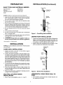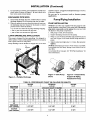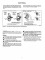
1
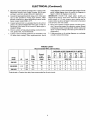
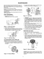
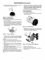
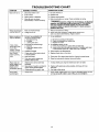
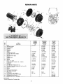
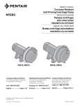
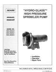
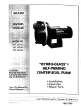
SEARS
OWNER'S
MANUAL
MODEL NOS.
390.2622
390.262553
MODELNO.
390.2622
390.262553
390.2623
MODEL NO. 390.2623
I:RRFTSNFIN°
CAUTION:
Read and Follow
All Safety Rulesand
Operating Instructions
Before First Use of
This Product.
Save ThisManual For
Future Reference.
HYDROGLASS ®
HIGH PRESSURE
SPRINKLER PUMP
• Safety Instructions
• Installation
• Electrical
• Maintenance
• Repair Parts
Sears, Roebuck and Co., Hoffman Estates, IL 60179
PP4NTED
IN U.S.A.
U.S.A.
FormNo.F642-04710 (8/6/o4)
CONTENTS
INTRODUCTION
INTRO DU CTION/WARR.MNITy
..........................................
SAFETY ...............................................................................
PREPARATION
....................................................................
INSTALLATION
................................................................
2
2
3
3_i
ELECTRICAL .....................................................................
OPERATION
54_
........................................................................
MAINTENANCE
11
FOR SAFE INSTALLATION
all safety
instructions
in this
DANGER
serious personal
ignored.
injury,
[&WARNING_wPdRNI_IG
cause serious personal
age if ignored.
minor personal
The word
important
about
death
or major
warns
injury,
[ A CAUTION ]CAUTION
cause
warns
hazards
about
death
hazards
damage
that
or major property
warns about hazards
injury or property
NOTICE indicates special
but not related to hazards.
that will cause
property
if
can
dam-
that will or can
damage
instructions
if ignored.
which
AND
OPERATION!
2. Follow local and/or
codes when installing
_k This is the safety alert symboL
When you see this
symbol on your pump or in this manual, look for one of the
following signal words and be alert to the potential
for personal injury!
_
in our warranty.
10
REPAIR PARTS ..................................................................
Carefully
read and follow
manual
or on pump.
cover
8-9
.......................................................
RULES
and cannot
7
...............................................................
TROUBLESHOOTING
Please take a few minutes to read our instructions
before you
install and use your pump. This will help you obtain the full
benefits from this pump. It will also help you avoid any needless service costs that result from causes we cannot control
are
1. To avoid risk of serious bodily injury and property
damage, read safety instructions
carefully
before installing
pump.
national
pump.
plumbing
and
electrical
3. Keep the well covered while instalfing pump to prevent
leaves and other debris from Falling into well, contaminating well and possibly damaging pump.
4. Protect pump and piping system from freezing. Allowing
pump or water system to freeze could severely damage
pump and voids warranty.
] _kWARNING]Hazardous
Voltage.
cause death,
or start fires.
5. Disconnect
electrical
working on pump.
power
source
Can shock,
before
burn,
installing
6. Ground pump with a ground wire run from grounding
on motor to a grounded
lead in the service panel.
or
lug
7. Line voltage and frequency
of electrical
power supply
must agree with motor nameplate.
8.Use of fuses or wire smaller than size recommended
in
owner's manual can cause overheating,
v_tll void warranty.
possible
9. Pump water only with this pump.
10. Do not run pump dry. To do so will damage
cause leaking and property
damage.
fires, and
seals and can
PREPARATION
BASIC TOOLS
AND
MATERIALS
Pipe Wrenches
Hacksaw
Adjustable Wrench
Knife
NOTICE:
1.
Depth
INSTALLATION
NEEDED
to water
must
not be more
i Tee
and Plug
than
20'.
Be sure water is clear of sand.
and void the warranty.
3.
Protect pump and all piping from freezing. Freezing will
split pipe, damage pump and void the warranty. Check leeally for frost protection
requirements
(usually pipe must
be 12" below frost line and pump must be insulated).
all pipes
and foot
Be sure
shape.
5.
No air pockets
6.
No leaks in suction pipe.
Stik I to seal pipe joints.
7.
Unions installed near pump and water
servicing. Leave room to use wrenches.
8.
[AWARNINGIPump
body may explode
booster pump. DO NOT use in a booster
Co., Chicago,
/
Sand will plug the pump
4.
in suction
Sanitary
Well Seal
and reduce
as possible:
2.
Chemical
Suction Pipe
Screwdriver
Check Valve
Teflon Tape
Long runs and many fittings increase friction
flow. Locate pump as close to water source
use as few elbows and fittings as possible.
' Lake
valve
are clean
Foot
Valve
and in good
Strainer
pipe.
Use Teflon
2590 0996
tape or Plasto-Joint
Figure I - Cased/Dug
source
DRIVEN
ffused
as a
1. Inspect
strainer
WELL
method
below
2.
which
POINT
Install a check valve in piping as shown in Figure 2. Flow
arrow on check valve must point toward pump.
matches
Suction Pipe
to Pump
INSTALLATION
foot valve to be sure
to be sure it is clean.
it works
freely.
Inspect
Check-_.
Valve
2. Connect foot valve and strainer to the first length of suction pipe and lower pipe into well. Add sections of pipe
as needed, using Teflon tape on male threads. Be sure that
all suction pipe is leakproof or pttmp v¢tll lose prime and
fail to pump. Install foot valve 10 to 20 feet below the lowest level to which water will drop while pump is operating (pumping water level). Your well driller can furnish
this information.
3.
INSTALLATION
1. Connect the suction pipe to the drive point as illustrated in
Figure 2. Keep horizontal pipe run as short as possible. Use
Teflon tape on male pipe threads. Multiple well points may
be necessary to provide sufficient water to pump.
application_
IUinois.
NOTICE: Use the installation
your well type.
Well Installation
will aid in
INSTALLATION
CASED
(Continued)
Drive point i
below water
level
Drive
Coupling
To prevent sand and sediment
from entering the pumping system, the foot valve/strainer
should be at least 5 feet
above the bottom of the well.
Drive
Point
4. When the proper depth is reached, install a sanitary well
seal over the pipe and in the well casing. Tighten the bolts
to seal the casing.
5. When using a foot valve, a priming
in Figure 1 are recommended.
2589 0996
tee and plug as shown
Figure
2 - Driven
Point
Installation
DUG WELL OR OPEN WATER
INSTALLATION
HORIZONTAL
PUMP
1. Follow
1. Never install a suction pipe
tion tapping of the pump.
cased
well installation,
steps
1, 2, 3 and 5.
3
PIPING
FROM WELL
that
is smaller
than
TO
the suc-
INSTALLATION
2. To aid priming on driven point installations, install a line
check valve as shown in Figure 2. Be sure check valve
flow arrow points toward pump.
DISCHARGE
1.
PIPE SIZES
(Continued)
sprinkler systems. A suggested mtdtiple discharge to service
is shown in Figure 3.
Do not use
application.
Pump/Piping
If increagmg
discharge
pipe size, install reducer in pump
discharge
tapping. Do not increase pipe size by stages.
2. When the pump is set away from the points of water use,
the discharge
pipe size should be increased
to reduce
pressure losses caused by friction.
in a pressure
PUMP
tank
or booster
pump
Installation
INSTALLATION
• Up to 100' run: Same size as pump
discharge
• 100' to 300' run: Increase
one pipe
size.
NOTICE: Use Teflon tape supplied with the pump for making all threaded
connections
to the pump itself. Do not use
pipe joint compounds
on the pump:
they can react with
the plastic in the pump components.
• 300' to 600' run: Increase
two pipe
sizes.
1. Bolt pump
LAWN
SPRINKLING
tapping.
2.
APPLICATION
This pump is designed for lawn sprinkling.
It is designed to
deliver plenty of water at full sprinkler pressure.
It can pump
from a pond, cistern or well points.
Pump
discharge
can be divided
to supply
two
(2) or more
Support
to solid, level foundation.
all piping
connected
to the pump.
3. Wrap 1-1/2 to two layers of Teflon tape clockwise
(as you
face end of pipe) on all male threads being attached
to
pump.
4.
Tighten
joints hand
tight plus 1-1/2 turns. Do not over-
tighten.
NOTICE: Install pump as close to water source as possible.
Long piping runs and many fittings create friction and reduce flow.
To
Service
Priming
Plug
Use schedule 80 or iron pipe. See "Well Pipe Installation"
more information.
for
Valve
846 0494
Figure 3 - Multiple
DISCHARGE
PRESSURE
PSI
10
15
20
25
30
35
4O
45
50
DISCHARGE
PIPE TAPPING
SUCTION
PIPE TAPPING
Figure 4 - Bolt Pump
Down
Discharge
TABLE II - PERFORMANCE
3_,2622
1H.P.
5'
55
51
45
38
31
23
17
10'
49
46
42
35
28
19
13
15'
48
45
39
32
24
16
8
20'
45
44
37
29
20
11
-
CHART (IN GALLONS
Figure 5 - Independently
Support All Piping
Attached To Pump
PER MINUTE)
390.262553
1-1/2H.P.
DISTANCE ABOVETO
5'
10'
15'
67
61
56
66
58
55
61
56
54
55
52
51
48
45
44
39
37
34
33
27
20
10
14
8
390.2623
2 H.P.
WATER
20'
46
45
44
43
37
28
11
-
5'
69
65
59
52
47
42
34
25
14
10'
67
63
56
50
45
38
30
18
7
1-1/2" NPT
1-1/2" NPT
2" NPT
1-1/2" NPT
1-1/2" NPT
2" NPT
15'
65
60
54
48
42
35
27
13
-
20'
62
58
52
45
40
32
23
10
ELECTRICAL
Connection
diagram for dual voltage, single-phase
motors.
Your dual-voltage
motor's terminal board (under the motor
end cover) will match one of the diagrams below. Follow
that diagram ff necessary
to convert
motor to 115 Volt
power.
Connect power supply wires to L1 and L2. For 3-phase motors, or if motor does not match these pictures, follow the
connection
diagram on the motor nameplate.
230 Volt to 115 Volt Conversion, Plug-in Type:
Move plug to change voltage.
230 Volt to 115 Volt Conversion, Plug-in Type:
1. Pull plug
straight
out from
terminal
board;
2.
Plug in again
with arrow
on plug
pointing to
'115 Volts'.
V
g Point
Power Supply Wires
Clamp the power cable to prevent
strain on the spade connectors.
Clamp the power cable to prevent
strain on the terminal screws.
Connect the green (or bare copper) ground
wire to the green ground screw.
Figure 6 - 115/230V
[AWARNING_Hazardous
cause death. Disconnect
pump or motor. Ground
supply.
Connect the green (or bare copper) ground
wire to the green ground screw.
Dual Voltage Single Phase Wiring
voltage.
power
motor
Can
shock,
burn,
_._( I%j ®_
Diagram.
A
Use wire size specified
in Wiring
Chart
If possible,
connect
pump
to a separate
circuit
with no other
appliances
on it.
or
to motor before working on
before connecting
to power
3782 1000
WIRING
Wire
motor
according
to diagram
on
nameplate.
If nameplate
diagram
differs
diagrams
above, follow
nameplate
diagram.
AGround
motor
before
connecting
to electrical
power
supply.
Failure to ground
motor can cause
severe
or fatal electrical
shock
hazard.
1. Install, ground,
wire and maintain
this pump in accordance with electrical
code requirements.
Consult your
local building inspector
for information
about codes.
ADo
A
not
ground
A
(Page 6).
branch
to a gas supply
2.
line.
To avoid dangerous
or fatal electrical
OFF power
to motor
before
working
cal connections.
shock,
turn
on electri-
A
Supply
voltage
must be within
±10% of nameplate voltage.
Incorrect
voltage
can cause fire or
damage
motor
and voids warranty.
If in doubt consult
a licensed
electrician.
5
motor
from
Provide a correctly
fused disconnect
switch for protection while working on motor. Consult local or national
electrical codes for switch requirements.
ELECTRICAL
3.
Disconnect
power before servicing motor or pump. If the
disconnect
switch is out of sight of pump, lock it open
and tag it to prevent unexpected
power application.
4.
Ground the pump permanently
using a wire of the same
size as that specified
in wiring
chart (below).
Make
ground connection
to green grounding
terminal under
motor canopy marked GRD. or @.
(Continued)
wiring diagram on motor nameplate against Figure 6. If the
motor wiring diagram does not match the diagrams in
Figure 6, follow the diagram on the motor.
IMPORTANT: 115/230 Volt single phase models are
shipped from factory with motor wired for 230 volts. If
power supply is 115 volts, remove motor canopy and reconnect motor as shown in Figure 6. Do not try to run motor
as received on 115 volt current.
5. Connect
ground wire to a grounded
lead in the service
panel or to a metal underground
water pipe or well caSing at least 10 feet long. Do not connect to plastic pipe or
insulated fittings.
6.
Protect current carrying and grounding
cuts, grease, heat, oil, and chemicals.
7.
Connect current
L2 under motor
carrying
canopy.
conductors
from
conductors
to terminals
When replacing
motor,
L1 and
check
8.
Motor has automatic
internal
thermal overload
protection. If motor has stopped for unknown
reasons, thermal
overload may restart it unexpectedly,
which could cause
injury or property damage. Disconnect
power before servicing motor.
9.
If this procedure
consult a licensed
or the wiring
electrician.
diagrams
are confusing,
WIRING CHART
Recommended Wire and Fuse Sizes
DISTANCE IN FEET FROM MOTOR TO METER
Max,
Branch
Fuse*
Rating*
Amps
Min,
Wire
Size
0'
TO
50'
51'
TO
100'
101'
TO
200'
201'
TO
300'
301'
TO
400'
401'
TO
500'
Pump
Model
HP
Volt
Load
Amps
390,2622
1
115
230
14.2
7.6
20
15
12
14
12
14
12
14
8
14
6
14
6
12
4
10
390.262553
1-1/2
115
230
19.2
9.6
25
15
10
14
10
14
10
14
8
14
6
12
4
10
4
10
390.2623
2
230
12.0
15
14
14
14
14
12
10
10
WIRE SIZE
*Dual element or Fusetron time delay fuses recommended for all motor circuits.
6
OPERATION
PRIMING
THE PUMP
NOTICE: 'Priming' refers to the pump expelling all air in the
system and beginning to move water from its source out into
the system. It does not refer only to pouring water into the
pump (although
pouring water in is usually the first step).
NOTICE: NEVER run pump
dry. Running pump
water in it will damage seals and can melt impeller
fuser. To prevent
damage,
fall pump
with water
starting.
1.
Remove
priming
plug (Figure
without
and difbefore
7).
Figure 9 - Run Ten Minutes
!
Or Less
If no water is produced within 10 minutes, stop pump,
release all pressure, remove priming plug, refill and try
again.
[AWARNING_Hazardous
pressure
and risk of explosion and scalding. If pump is run continuously
at no
flow (that is, with discharge shut offor without priming), water may boil in pump and piping system.
Under steam pressure,
pipes may rupture, blow off of
fittings or blow out of pump ports and scald anyone
near,
Figure
7 - Remove
Priming
Plug
2.
Make sure suction and discharge valves and any hoses on
discharge
side of pump are open.
3.
Fill pump
and suction
pipe with water.
Figure I 0 - Do Not
Shut Off
To prevent
Replace
priming
tighten plug.
plug,
using
Teflon
tape
on
nozzle,
etc.) is
B. If pump fails to produce water when attempting
to prime,
release all pressure,
drain pump and refill with cold water
after every two attempts.
thread;
C. When priming, monitor pump and piping temperature. If
pump or piping begin to feel warm to the touch, shut off
pump and allow system to cool off. Release all pressure
in system and refill pump and piping with cold water.
NOTICE: If a priming tee and plug have been provided
for a long horizontal
run, be sure to fill suction pipe
through this tee and replace plug. (Don't forget to Teflon
tape the plug.)
5.
Discharge
do the following:
A. Be sure discharge
(valve, pistol grip hose
open whenever
pump is running.
Figure 8 - Fill Pump Before Starting
4.
explosion,
Run Pump With
Start pump: water should be produced
in 10 minutes or
less, the time depending
on depth to water (not more
than 20') and length of horizontal
run (10' of horizontal
suction pipe = 1' of vertical lift due to friction losses in
the pipe).
7
MAINTENANCE
Pump and piping need not be disconnected
to repair or replace motor or seal (see Figure 12). If motor is replaced, replace the shaft seal (Key No. 6, Page 11). Keep one on hand
for future use.
2. If impeller must be replaced, loosen two machine screws
and remove motor canopy (see Figure 14).
Be sure to prime pump before starting.
NOTICE:
Check motor label for lubrication
instructions.
The mechanical
shaft seal in the pump is water lubricated
and sell-adjnsting.
NOTICE: Drain pump
when it might freeze.
PUMP
when
disconnecting
from service
_WARNING
To avoid electrical
shockhazard, use
insulated-handM
screwdriver to short
capacitorterminals
as shown.
or
DISASSEMBLY
Figure
1. Disconnect
power to motor.
NOTICE: Mark wires for correct
.
Figure
I I - Disconnect
clamp
14 - Hold Shaft
assembly.
4.
Unscrew
capacitor clamp and remove
disconnect
capacitor wires to motor.
5.
Slide 7/16" open end wrench
in behind
spring loaded
switch
on motor end of shaft; hold motor shaft with
wrench
on shaft flats and unscrew
impeller
by turning
counterclockwise
when looking into eye of impeller.
6.
To reinstall,
7.
See directions
Power
2.
Remove
3.
Remove pump base mounting bolts. Motor assembly and
back haft of pump can now be pulled away from pump
front half (Figure 12). CAREFULLY remove O-Ring.
I _kWARNING ]Capacitor
voltage
may be hazardous.
To discharge
capacitor,
hold insulated
handle
screwdriver BY THE HANDLE and short capacitor
terminals
together (see Figure 14). Do not touch metal screwdriver
blade or capacitor terminals. If in doubt, consult a qualified electrician.
(see Figure 12).
REMOVING
1. Follow
_
Figure
12 - Slide Motor
NOTICE:
First, follow instructions
1. Remove four
move diffuser
be cleaned.
o4_4
OLD
instructions
steps 1 through
"Pump
5.
Reassembly,"
Page 10.
SEAL
under
"Pump Disassembly".
IMPELLER
under
"Pump Disassembly".
screws fastening
diffuser to seal plate; re(see Figure 13). Exposed impeller can now
Figure
Figure
under
Do not
2. Follow steps 2 through
5 under "Cleaning/Replacing
Impeller.
3. Unscrew
four nuts holding pump back hall to motor.
Remove rotating haft of seal by placing two screwdrivers
under back haft of pump body and carefully prying up
(Figure 15). Back haft of pump body vdll slide off shaft,
bringing seal with it.
Back
CLEANING/REPLACING
reverse
capacitor.
13 - Remove
Diffuser
15 - Remove Seal plate
NOTICE: Be sure you do not scratch or mar shaft; if shaft is
marred, it must be dressed smooth with fine emery or crocus cloth before installing new seal. DO NOT reduce shaft
diameter!
MAINTENANCE
4.
Place pump body half face down on flat surface and tap
out stationary half of seal (see Figure 16).
(Continued)
9.
Hold motor shaft with 7/16" open end wrench on shaft
flats (Figure 14, Page 8) and screw impeller onto shaft. Be
sure you do not touch
capacitor
terminals
with
body or any metal object. Tightening impeller will automatically
locate seal in correct position.
10. Remount diffuser on pump body half with five screws.
PUMP
REASSEMBLY
1. Clean O-Ring and O-Ring groove.
2.
Figure
Put O-Ring in groove on face of flange; put pump
together (see Figure 18).
halves
16 - Tap Out Seal
INSTALLING
NEW
SEAL
1. Wet outer edge of Rubber Cup on ceramic seat with fiquid soap. Be sparing!
2. Put clean cardboard
washer
on seal face. With thumb
pressure,
press ceramic seal half firmly and squarely into
seal cavity in seal plate (see Figure 17). Polished face of
ceramic seat is up. If seal will not seat correctly, remove,
placing seal face up on bench. Reclean cavity. Seal should
now seat correctly.
Figure
3.
18 - Assemble
Pump
BE SURE inside of clamp is clean. Place clamp on pump
halves; snug up. Alternately
tighten screw and tap clamp
with mallet to seat O-Ring (see Figure 19).
4770194
Figure
3.
17 - Press in New Seal
ff seal does not seat correctly after recleaning cavity, place
cardboard
washer over polished seal face and carefully
press into place using a piece of standard 3/4" pipe as a
press.
NOTICE:
Be sure you do not scratch
seal face.
4.
Dispose of cardboard
washer and recheck
sure it is free of dirt, foreign particles,
grease.
5.
Inspect
6.
Reassemble
pump
is right side up.
shaft to be sure it is free of nicks
body
half to motor
7. Apply liquid soap sparingly (one drop
side diameter of rotating seal member.
8.
seal face to be
scratches
and
and scratches.
flange.
BE SURE it
is sufftcient)
to in-
Slide rotating seal member (carbon face first) onto shaft
tmtil rubber drive ring hits shaft shoulder.
NOTICE: Be sure not to nick or scratch carbon face of seal
when passing it over threaded
shaft end or shaft shoulder.
The carbon surface must remain clean or short seat life vdll
result.
Figure
19 - Tap Clamp While
4.
Replace
base mounting
5.
Replace
motor
6.
7.
Prime pump according
Check for leaks.
wiring;
Tightening
bolts.
close draincock.
to instructions.
See "Operation."
TROUBLESHOOTING
SYMPTOM
Motor will net run
POSSIBLE CAUSE(S)
1. Disconnect switch is off
2. Fuse is blown
3. Startingswitch is detective
4. Wires at motor are loose,
disconnected, or wired incorrectly
CHART
CORRECTIVE ACTION
1. Be sure switch is on
2. Replace fuse
3. Replace starting switch
4. Refer to instructionson wiring. Check and tighten all wiring.
AWARNING] Capacitor voltage may be hazardous. To discharge
capacitor, hold insulated handle screwdriver BY THE HANDLE
and short capacitor terminals together. Do not touch metal
screwdriver blade or capacitor terminals. If in doubt, consult a
qualified electrician.
Motor runs hot and 1. Motor is wired incorrectly
overload kicks off
2. Voltage is too low
1. Refer to instructions on wiring
2. Check with power company. Install heavier wiring if wire
size is too small (See Electrical, Pages 5 and 6)
Motor runs but no
water is delivered
1. In new installation:
*(Note: Check
prime before looking for other
causes. Unscrew
priming plug and
see if there is
water in priming
hole.)
"1.
'2.
3.
4.
5.
6.
Pump in new installation did
not pick up prime through:
a. Improper priming
b. Air leaks
c. Leaking foot valve
Pump has lost prime through:
a. Air leaks
b. Water level below suction
of pump
Impeller is plugged
Check valve or foot valve is stuck
in closed position
Pipes are frozen
Foot valve and/or strainer are
buried in sand or mud
a. Re-prime according to instructions
b. Check all connections on suction line
c. Replace foot valve
2. In installation already in use:
a. Check all connections on suction line and shaft seal
b. Lower suction line into water and re-prime. If receding water level
in well exceeds suction lift, a deep well pump is needed
3. Cleen impeller; see Maintenance
4. Replace check valve or foot valve
5. Thaw pipes. Burypipes below frost line. Heat pit or pump house.
6. Raise foot valve and/or strainer above well bottom
Pump does not
1. Water level in well is lower than
deliver water to full
estimated
capacity (Also
2. Steel piping (if used) is corroded or
check point 3
limed, causing excess friction
immediately above) 3. Offset piping is too small in size
2. Replace with plastic pipe where possible, otherwise with new
steel pipe
3. Use larger offset piping
Pump leaks
around clamp
1. STOP PUMP, tighten clamp nut 1-2 turns. Alternately tighten nut and
and tap clamp with mallet to seat O-Ring. Do not overtighten
1. Clamp loose
1. A deep well jet pump may be needed (over 20 ft. to water)
10
REPAIR PARTS
8A
1
11A
2
16 18
/
12
9
!0
11
/
13
Part
Description
Key
No.
1
1A
1B
1C
1D
1E
2
3
4
5
6
7
8
8A
9
390.2622
115/230V
60 Cy/1 Ph
1 HP
Motor
Overload Protector
Terminal Board
Contactor
Governor
Capacitor
Slinger
Priming Plug 1/2" NPT
Tank Body Back Half Complete
O-Ring
Shaft Seal for 5/8" Shaft
impeller
Impeller Screw
Diffuser
Diffuser
Screw - #8 - 32 RH
J216-1029
390.262553
115/230V
60 Cy/1Ph
1-1/2HP
17351-0009
J218-956C
U18-1342
U18-1180
U18-1098
U18-128
U18-525
17351-0009
A100GSL
U18-1406
U18-1180
U18-1098
U18-128
U18-525
17351-OOO9
L176-47P1
U9-399
U109-6A
C105-92PVB
L176-47P1
U9-399
U109-6A
C105-92PBBB
C3-189P1
U9-228A
U109-6A
C105-214PFA
C30-51SS
C1-258PCA
C1-258PCA
U30-869SS
U30-869SS
C19-54SS
C176-53PA
C19-54SS
C176-53PA
U212-68T
U9-226
C4-42P
U212-68T
U9-226
C4-42P
C35-11
U43-11ZP
C35-11
U43-11ZP
(1 and 1-1/2 HP - 4 Req'd; 2 HP - 2 Req'd.)
Lockwasher
10
11
11A
12
"V" Clamp
Tank Body Front Half (Incl. No. 12)
Tank Body Front Half Complete (Incl. Nos. 3 and 12)
Draincock - 1/4 NPT
13
14
O-Ring
Base
15
16
17
18
19
20
21
Flat Washer 5/16 (2 Req'd.)
Nut - 5/16 - 18 (4 Req'd.)
Rubber Pad
Lock Washer - 5/16 (2 Req'd.)
Capscrew, 3/8 - 16 x 1-3/4" (2 Req'd.)
Flat Washer 5/16 (2 Req'd.)
Capscrew, 3/8 - 16 x 1" (2 Req'd.)
390.2623
230V
60 Cy/t Ph
2 HP
C1-274P
U30-542SS
U43-21SS
C19-37A
C176-62PA
U212-66T
U9-393
C4-42P
C35-11
U30-77SS
U43-42SS
U30-74SS
• Not illustrated
* Standard hardware item. Purchase locally.
1!
SEARS
I:RRFTSMRN°
OWNER'S
MANUAL
HYDROGLASS ®
HIGH PRESSURE
SPRINKLER PUMP
Model No.
390.2622
390.262553
390.2623
For the repair or replacementpartsyouneed
Call7 am - 7 pm, 7 days a week
1-800-366-PART
(1-800-366-7278)
Forin-homemajorbrandrepair service
Call24 hours a day, 7 days a week
1-800-4-REPAIR
(1-800-473-7247)
The model number of
your Sprinkler Pump will
be found on a plate
attached to the side of
the pump body.
When requesting service
or ordering parts, always
give the following
information:
• ProductType
• Model Number
• PartNumber
• Part Description
For the locationof a
SearsRepairServiceCenterin yourarea
Call24 hours a day,7 daysa week
1-800-488-1222
For informationon purchasinga Sears
MaintenanceAgreementor to inquire
aboutan existingAgreement
call 9 am - 5 prn, Monday-Saturday
A
1-800-827-6655
SEARS
r;tP#Jll
;Jk'i
:i;_J[#;[
America's
Repair Spscialists
Sears, Roebuck and Co., Hoffman Estates, IL 60179
U.S.A.