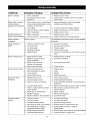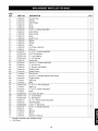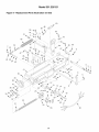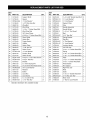
1
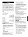
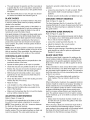
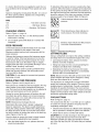
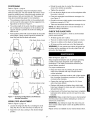
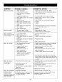
Operator's
Manual
7 x 12"
BAND SAW
Model No.
351.226121
CAUTION: Read and follow
all Safety Rules and Operating
Instructions before First Use
of this Product.
Sears, Roebuck and Co., Hoffman
www.sears.com/craftsman
16799.05 Draft (04/25/06)
Estates, IL 60179 U.S.A.
PREPARE
Warranty
....................................
SafetyRules...............................
Unpacking..................................
Assembly
...................................
Installation
.................................
Operation.................................
Maintenance
.................................
Troubleshooting
...........................
PartsIllustration
andListforBase............
PartsIllustration
andListforBed.............
PartsIllustration
andListforHead............
PartsIllustration
andListforGearBox.........
2
2-3
3
3
3-4
4-9
9
10-11
12-13
14-15
16-17
18-19
Keep work area clean. Cluttered work areas invite
accidents.
•
Do not use power tools in dangerous environments.
Do not use power tools in damp or wet locations. Do
not expose power tools to rain.
•
•
Work area should be properly lighted.
Proper electrical receptacle should be available for
tool. Three-prong plug should be plugged directly
into properly grounded, three-prong receptacle.
•
Extension cords should have a grounding prong and
the three wires of the extension cord should be of
•
the correct gauge.
Keep visitors at a safe distance from work area.
Keep children out of workplace. Make workshop
childproof. Use padlocks, master switches or remove
switch keys to prevent any unintentional use of
power tools.
TOOL SHOULD
If this Craftsman tool fails due to a defect in material or
AREA FOR JOB
•
•
FULL ONE YEAR WARRANTY
WORK
BE MAINTAINED
•
Always unplug tool prior to inspection.
•
Consult manual for specific maintaining and adjusting procedures.
•
Keep tool lubricated and clean for safest operation.
•
This warranty applies only while this tool is in the
United States.
Remove adjusting tools. Form habit of checking to
see that adjusting tools are removed before switching machine on.
•
This warranty gives you specific legal rights, and you
may also have other rights, which vary, from state to
state.
Keep all parts in working order. Check to determine
that the guard or other parts will operate properly
and perform their intended function.
•
Check for damaged parts. Check for alignment of
moving parts, binding, breakage, mounting and any
other condition that may affect a tool's operation.
•
A guard or other part that is damaged should be
properly repaired or replaced. Do not perform
makeshift repairs. (Use parts list provided to order
replacement parts.)
workmanship within one year from the date of purchase,
call 1-800-4-MY-HOME ®TO ARRANGE FOR FREE
REPAIR.
If this tool is used for commercial or rental purposes,
this warranty will apply for only 90 days from the date of
purchase.
Sears, Roebuck and Co., Dept. 817WA, Hoffman
Estates, IL 60179
WARNING:
For your own safety, read all of the
instructions and precautions before operating tool.
KNOW HOW TO USE TOOL
CAUTION: Always follow proper operating procedures
as defined in this manual -- even if you are familiar
with use of this or similar tools. Remember that being
careless for even a fraction of a second can result in
severe personal injury.
•
Use right tool for job. Do not force tool or attachment
to do a job for which it was not designed.
•
Disconnect tool when changing blade.
•
Avoid accidental start-up. Make sure that the tool is
in the "off" position before plugging in.
Wear proper apparel. Do not wear loose clothing,
gloves, neckties, rings, bracelets or other jewelry
which may get caught in moving parts of machine.
Wear protective hair covering to contain long hair.
•
Do not force tool. It will work most efficiently at the
rate for which it was designed.
•
Keep hands away from moving parts and cutting
surfaces.
Wear safety shoes with non-slip soles.
Wear safety glasses complying with United States
ANSI Z87.1. Everyday glasses have only impact
resistant lenses. They are NOT safety glasses.
Wear face mask or dust mask if operation is dusty.
•
Never leave tool running unattended. Turn the power
off and do not leave tool until it comes to a complete
stop.
Do not overreach. Keep proper footing and balance.
BE PREPARED
•
•
•
•
•
•
FOR JOB
•
•
Be alert and think clearly. Never operate power tools
when tired, intoxicated or when taking medications
that cause drowsiness.
© Sears, Roebuck and Co.
2
Never stand on tool. Serious injury could occur if tool
is tipped or if blade is unintentionally contacted.
•
Know your tool. Learn the tool's operation, application and specific limitations.
ATTACH WORK
STOP ASSEMBLY
•
Use recommended accessories (refer to page 15).
Use of improper accessories may cause risk of
injury to persons.
•
Insert end of work stop rod (Key. No. 8) into bed (Key
No. 41 ). Secure position of rod with socket head bolt
(Key No. 61 ).
•
Handle workpiece correctly. Protect hands from possible injury.
•
Slide work stop (Key No. 6) onto work stop rod and
secure with wing bolt (Key. No. 5).
•
Turn machine off if it jams. Blade jams when it digs
too deeply into workpiece. (Motor force keeps it
stuck in the work.) Do not remove jammed or cut off
pieces until the saw is turned off, unplugged and the
blade has stopped.
•
Adjust the work stop as described in Operation,
page 9.
WARNING:
The operation of any power tool can result
in foreign objects being thrown into the eyes, which can
result in severe eye damage.
•
Insert filter with hex head bolt and hex nuts (Key
Nos. 31,32 and 19) into recess in chip tray (Key. No
30).
Always wear safety goggles complying with United
States ANSI Z87.1 (shown on package) before commencing power tool operation. Safety goggles are available through your Sears catalog.
•
Center of filter should be curved up so chips cannot
get under filter.
Refer to Figure 9, page 14.
INSTALL
FILTER
Refer to Figure 8, page 12.
MOTOR
Check for shipping damage. If damage has occurred, a
claim must be filed with carrier. Check for completeness. Immediately report missing parts to dealer.
The band saw comes assembled as one unit. Additional
parts which need to be fastened to the saw should be
located and accounted for before assembling:
Filter with bolt and nuts, work stop, work stop rod, wing
bolt, two axles, four wheels and four cotter pins.
IMPORTANT: Bed is coated with a protectant. To
ensure proper fit and operation, remove coating.
Coating is easily removed with mild solvents, such as
mineral spirits, and a soft cloth. Avoid getting cleaning
solution on paint or any of the rubber or plastic parts.
Solvents may deteriorate these finishes. Use soap and
water on paint, plastic or rubber components. After
cleaning, cover all exposed surfaces with a light coating
of oil. Paste wax is recommended for table top.
MOUNT WHEEL
ASSEMBLIES
Refer to Figure 8, page 12.
•
Slide axles (Key No. 13) through holes in left and
right legs (Key Nos. 15 and 33). Ends of axles
should extend 11/2"outside of legs.
•
Raise or prop up right leg approximately 3". Slide
wheels (Key. No. 12) onto axle.
•
Slide spacers (Key. No. 11) onto axle.
•
Insert cotter pins (Key. No. 14) through holes in axle.
Bend ends of cotter pins back to secure in place.
•
Repeat steps above to mount wheels onto the right
side of bandsaw.
The band saw is supplied with a 1 HP motor.
The 115 Volt AC motor has the following specifications:
Horsepower (max. developed) ...................
Voltage ...............................
Amperes .................................
Hertz .....................................
Phase ..................................
RPM ....................................
2
115/230
14/7
60
Single
1725
WARNING: All electrical connections must be performed by a qualified electrician.
ELECTRICAL
WARNING:
CONNECTIONS
Make sure unit is off and disconnected
from power source any time wiring is inspected.
POWER
SOURCE
Band Saw is prewired for 115 volt, 60 HZ power source.
See figure 3 for wiring schematic.
The motor is designed for operation on the voltage and
frequency specified. Normal loads will be handled safely on voltages not more than 10% above or below the
specified voltage.
Running the unit on voltages which are not within the
range may cause overheating and motor burn-out.
Heavy loads require that the voltage at motor terminals
be no less than the voltage specified. Power supply to
the motor is controlled by a single pole toggle switch.
GROUNDING
INSTRUCTIONS
WARNING:
Improper connection of equipment
grounding conductor can result in the risk of electrical
shock. Equipment should be grounded while in use to
protect operator from electrical shock.
•
Check with a qualified electrician if grounding
instructions are not understood or if in doubt as to
whether the tool is properly grounded.
Thistoolis equippedwithanapproved3-conductor
cordratedat 150Vanda threepronggrounding
type
plug(seeFigure1) foryourprotectionagainstshock
hazards.
• Grounding
plugshouldbepluggeddirectlyintoa
properlyinstalledandgrounded3-pronggroundingtypereceptacle,
as shown(Figure1).
rigid green tab or terminal on the side of the adapter
must be securely connected to a permanent electrical ground such as a properly grounded water pipe,
a properly grounded outlet box or a properly grounded wire system.
Many cover plate screws, water pipes and outlet boxes are
not properly grounded. To ensure proper ground, grounding means must be tested by a qualified electrician.
230 VOLT
ProperlyGrounded
Outlet..,,,.K_'il
3__rroO_
d_lnugg
Prong
•
•
To use the band saw with a 230V, single-phase
power supply, have a qualified electrician attach a
230 volt, 20/30A 3-prong plug onto band saw line
cord and install the proper connectors and receptacles to power supply.
•
See wiring diagram (Figure 3) for wiring instructions
for both motor and pump.
_._.._"4_
L_.J II
Figure1 - 3-Prong Receptacle
OPERATION
Do not remove or alter grounding prong in any manner. In the event of a malfunction or breakdown,
grounding provides a path of least resistance for
electrical shock.
WARNING:
Do not permit fingers to touch the terminals of plug when installing or removing from outlet.
•
Plug must be plugged into matching outlet that is
properly installed and grounded in accordance with
all local codes and ordinances. Do not modify plug
provided. If it will not fit in outlet, have proper outlet
installed by a qualified electrician.
•
Inspect tool cords periodically, and if damaged, have
repaired by an authorized service facility.
•
Green (or green and yellow) conductor in cord is the
grounding wire. If repair or replacement of the electric cord or plug is necessary, do not connect the
green (or green and yellow) wire to a live terminal.
Where a 2-prong wall
must be replaced with
receptacle installed in
Code and local codes
U
U
NOTE: Both motor AND pump must be rewired when
using 230V power supply.
EXTENSION
•
A temporary 3-prong to 2-prong grounding adapter (see
Figure 2) is available for connecting plugs to a two pole
outlet if it is properly grounded.
•
•
3-Pronu,,_u
_D,,_
_ ¢
_"
V
Figure3 - Motor and Pump Wiring Diagram
WARNING: This work should be performed by a qualified electrician.
_
230V
1,2, 3, 4 - Motor Leads
U, V - Power Supply
receptacle is encountered, it
a properly grounded 3-prong
accordance with National Electric
and ordinances.
Grounding Lug_
Adapter _
llS\J
ThisMakelsSure
Connected
to carry the current and maintain adequate voltage.
Use the table to determine the minimum wire size
(A.W.G.) extension cord.
•
Use only 3-wire extension cords having 3-prong
grounding type plugs and 3-pole receptacles which
accept the tool plug.
•
If the extension cord is worn, cut, or damaged in any
way, replace it immediately.
_'-----, H ToAKnown
Ground
2-Prong Receptacle
CORDS
The use of any extension cord will cause some drop
in voltage and loss of power.
Wires of the extension cord must be of sufficient size
EXTENSION CORD LENGTH
Figure 2 - 2-Prong Receptacle with Adapter
Wire Size
Do not use a 3-prong to 2-prong grounding adapter
unless permitted by local and national codes and
ordinances. (A 3-prong to 2-prong grounding adapter
is not permitted in Canada.) Where permitted, the
A.W.G.
Up to 25 ft ..................................
NOTE: Using extension cords over 25 ft. long is not
recommended.
4
16
Referto Figures4 through11.
The7 x 12" Horizontal
MetalCuttingBandSawprovidesspeedwithqualityof cutforfabrication
shops,
machineshops,maintenance
departments
andcontractors.Bladespeedrangesfrom125to270FPMtocuta
varietyof materialrangingformcastiron,toolsteel,
bronze,aluminum
andplastic.
Thefeedrateis regulatedbya hydraulic
cylinder.The
dialcontrolforthecylinderis accessible
duringall
stagesof properoperation
andcanbesetatanyfeed
ratewithinitsrange.Thewetcutoperationprovidesa
qualitycutandextendsbladelife.Featuresinclude
automatic
shutoff,industrialratedspeedreducer,heavy
gaugesteelconstruction,
castironwheels,pulleyshead
andbed.
Additionalfeaturesincludeswivelvisejawsforangle
cuts,builtin chiptrayandwheelassemblies.
Sawis
controlledbytoggleswitch.
•
Make sure enough coolant is available to keep
coolant pump (Key No. 5) submersed.
•
Secure the workpiece in a stable position.
•
Check that all guards are attached.
•
After turning the switch on, let the blade come to full
speed. Then lower the blade onto the workpiece slowly.
•
Keep hands away from the blade and all moving parts.
•
Always wear eye protection or face shield.
HORIZONTAL
Refer to Figure 9, page 14.
Horizontal stop bolt (Key No. 37) controls the position of
the head at the end of the cut. Head should contact the
horizontal stop when teeth are 1/8"below the surface of
the workbed.
HORIZONTAL
Blade speeds ..............
Blade size ........................
7" Rounds
7 x 8" Rectangle at 90 °
2 x 12" Rectangle at 90 °
4 x 6" Rectangle at 45 °
125, 215 and 270 FPM
3/4x .032 x 93"
Blade wheels .............................
Overall dimensions
...............
111/2"
491/2x 17 x 351/2
',
Weight ................................
Coolant pump .............
318 Ibs
2.25 Gallons per minute
Coolant trough .......................
SAFETY
3.4 Gallons
PRECAUTIONS
STOP ADJUSTMENT
Refer to Figure 9, page 14.
•
Place head in the horizontal position.
•
Loosen the nuts (Key No. 32) on the horizontal stop
bolt. Adjust the horizontal stop bolt so that the teeth
are 1/8"below the surface of the workbed.
•
Tighten the nuts to lock the position.
SPECIFICATIONS
Capacity ............................
STOP
AUTOMATIC SHUTOFF
Refer to Figure 9, page 14.
The switch is shut off when the blade passes through
the plane of the workbed. The switch should be shut off
as soon as the cut is finished.
IMPORTANT: Make sure the action of the switch is not
restricted by the horizontal stop.
LUBRICATION
All ball bearings are permanently lubricated. They
should not require further lubrication.
Refer to Figure 8, page 12.
If the tracking wheel or head pivot is disassembled for
any reason, wipe off the old grease before assembly.
WARNING:
cautions.
OIL LEVEL
•
Always observe the following safety pre-
Whenever adjusting or replacing any parts on the
band saw turn, switch off and remove plug from
power source.
•
Make sure the stops are positioned and that the
automatic shut-off is operating.
•
Check that the gear box has the proper amount of
lubricant.
•
Make sure the blade guides are positioned correctly.
•
Use the appropriate blade for the workpiece that is
being cut.
•
Use a sharp blade. Replace dull blades or blades
which are missing teeth.
•
Make sure the blade is tensioned properly and going
in the right direction.
•
Use the proper blade speed for the work.
•
For optimum performance, do not stall the motor or
reduce the speed. Use the proper feed pressure.
Refer to Figure 11.
•
•
The gear box relies on an oil bath to lubricate the
sliding surfaces and transfer heat. The vent bolt (Key.
No. 30) is vented to release pressure created by the
developed heat. Insufficient lubrication will cause the
gears to heat up and wear at an accelerated rate. If
the gear box is over filled, hot oil will escape through
the vent hole. The gear box is designed to take 10
ounces of 70-95 weight industrial gear oil.
The oil level should remain constant. If the level
changes, a defective gasket or seal should be
looked for and replaced.
•
If the gear box is worked on, the oil should be
replaced to avoid contamination.
•
Always add fresh oil and replace the oil seasonally,
to guard against break-down.
H
• Thesealbetweenthegearboxandthecoverplateis
a gasket(KeyNo.14).Ifcoverplateis removed,
the
surfaceshouldbecleanedanda newgasketshould
beapplied.
• Afterthefirstfiftyhoursofuse,thegearboxshould
bedrainedandrefilledwithindustrial
gearoil.
mounted to eccentric shafts (Key No. 5) and can be
adjusted.
BLADE
CHECKING
GUIDES
Band saw blade has to be twisted relative to the plane
in which it rotates. Blade must be properly positioned
relative to the workbed.
•
Spread the blade guides as far apart as possible.
•
Check that vise jaws are parallel and set for 90 ° cutoff.
•
Position the vise jaws to have the maximum separation that will not interfere with the blade guides.
•
With the head in horizontal position, use a square
against face of rear vise jaw and check that jaw is
90 ° to the side of blade.
to the
•
Check that the blade is in line with tracking and drive
wheels (Key Nos. 44 and 52).
Raise the head.
•
Look straight on at the cutting edge of the blade.
•
Make sure that the blade sides are parallel to the
sides of the bearings.
•
Make sure the bearings (Key No. 6) touch the blades
and can still be rotated by hand.
GUIDE
GUIDE
BRACKETS
If the bearings are positioned properly and the blade
is not square, one or both blade guide brackets (Key
Nos. 3 and 23) must be adjusted.
•
Loosen the socket head bolts (Key No. 11).
•
Adjust the bracket to the correct position.
•
Tighten the socket head bolts.
•
Check the guide bearings. Repositioning the blade
guide bracket can alter the previous adjustments.
Readjust if necessary.
SELECTION
Using the proper blade is
correct cutting conditions.
depending on the specific
blade. Some simple rules
all blades.
Refer to Figure 10, pages 16.
Check that the blade teeth are perpendicular
machined surface of the base.
BEARINGS
•
BLADE
GUIDES
•
THRUST
Refer to Figure 10, page 16.
NOTE: Since the blade position is related to both table
and the vise jaws, the relative position of the jaw to the
table is important. When assembled, the stationary jaw
must be perpendicular to the surface of the workbed.
ADJUSTING
Maintain eccentric shaft position and tighten hex nuts.
ADJUSTING
Entire guide assembly is positioned at the factory to
produce the proper twist and should not need adjustment, however, the position of blade guides should be
checked often.
•
•
The thrust bearings (Key No. 6) should be .003-.005"
(average thickness of a piece of paper) away from back
of blade. The thrust bearings are adjusted by moving
the guide bracket.
Inner guide bearings on the upper and lower guide assemblies keep the blade in line with the blade wheels. Outer
guide bearings keep the blade against the inner bearings.
BLADE
Loosen hex nuts (Key No. 15) with a wrench. Rotate
the eccentric shaft to locate bearings in desired
positions.
Refer to Figure 10, page 16.
Blade guides hold the cutting portion of the blade in a
plane which is perpendicular to both the workbed and
the stationary vise and keep the blade in line with its
natural path around the blade wheels.
CHECKING
•
important for setting up the
Blades are made differently
application intended for the
can still be applied to almost
Always remember to have at least three teeth in contact
with the work during a cut. When three teeth are in contact, the blade cannot straddle the work. This prevents a
tooth that enters the cut from encountering more material than it can remove.
•
"Shocking" occurs when blade teeth contact too
much material. This can strip the teeth from the
blade.
When cutting harder materials, the suggested minimum
number of teeth in contact is six because "shocking" on
harder materials has a more detrimental effect on the
blade. The optimum number of teeth in contact with the
workpiece distributes the blade forces among more
teeth to increase cutting efficiency and reduces blade
wear. The optimum range is from 6-12 teeth in contact
for soft materials, up to 12-24 teeth in contact for harder
materials.
BEARINGS
Refer to Figure 10, page 16.
•
If the blade is not perpendicular to the base or not in
line with the blade wheels, adjustment is necessary.
NOTE: There should be .000-.001" clearance between
the blade and the guide bearings.
Always have the maximum number of teeth in contact with the work to prevent the gullets of the teeth
from being clogged.
When choosing a blade, the overall size of the work is
not as important as the thickness average. The thickness average is the average width of the material which
the blade will contact during each cut. Figure 11
describes how the thickness average should be
The guide bearings are adjusted using an eccentric
location system. The inner guide bearings are fixed and
cannot be adjusted. The outer guide bearings are
6
calculated. The thickness average should be used when
choosing a blade for the optimum number of teeth in
contact, however, the three teeth rule should be applied
to the minimum thickness, not the thickness average.
CHECK TRACKING
Refer to Figure 5.
•
Raise the head. Open the wheel cover.
•
Insert a piece of paper between the blade and the
left side of the idler wheel.
•
Lift the belt cover and rotate the blade by turning the
motor pulley.
Every band saw should have at least one replacement
blade of each type used. Blade breakage is unpredictable. Consult a blade manufacturer for detailed information about available blades for specific uses.
•
Let the blade grab the paper. Rotate the pulley so
the paper goes around the wheel.
•
Refer to Figure 5 to determine if an adjustment is
needed.
REMOVING
TRACKING
Keeping a selection of sharp blades on hand will yield
better cuts. The blades may last longer because they
are less likely to be misused when the proper blade is
available.
BLADE
ADJUSTMENT
Refer to Figure 10, page 16.
Refer to Figures 5 and 10, page 7 and 16.
•
Raise the head and open the blade cover.
•
Loosen the outer guide bearings on the upper and
lower guide assemblies. No other guide bearings
should be moved.
•
With one hand, pinch the blade and the tracking
wheel together to protect against the possibility of
the blade popping off when tension is released.
The tracking is adjusted by positioning the tracking
wheel shaft (Key No. 36). The positioning is done with
the set screw (Key No. 30) only if the upper socket
head bolts (Key No. 29) are loose.
• Loosen the two socket head bolts.
•
•
Release the tension by slowly revolving the knob
(Key No. 40) counterclockwise.
Remove the blade.
REPLACING
•
Adjust the tilt with set screw. For correct tracking,
refer to Figure 4. Turn 1/4revolution at a time.
•
Check the blade tension and adjust if necessary.
•
Recheck the tracking.
•
Once the proper position has been found, tighten the
bolts securely.
THE BLADE
•
Make sure the outer guide bearings are loose.
•
Make sure the teeth are pointing in the right direction
(see Figure 4).
A sharp fold indicates
proper tracking.
Cut or ripped paper
indicates that the
blade is riding against
the flange of the
wheel. Adjusting screw
needs to be turned
counterclockwise.
Figure 4 - Blade Direction
•
Place the blade around the wheels and between the
guide bearings.
•
Hold the blade in position and apply tension.
•
Push the blade against the wheel flange.
•
Tighten the blade until it is properly tensioned. A properly tightened blade will ring slightly when the back of
the blade is plucked (like a string of an instrument).
•
Adjust the outer guide bearings.
•
Check for proper tracking (See Tracking Adjustment).
..,._
blade will ride off the
wheel. Adjusting screw
should
No fold be
indicates
turned the
clockwise.
Figure 5 - Tracking Adjustments
TRACKING
BLADE
Proper tracking is achieved when the drive wheel and
idler wheel are aligned. A blade that is not tracking correctly can come off the blade wheels. Although adjustment is rarely required, tracking should be checked frequently.
Refer to Figure 11, page 18.
CAUTION: Turn motor off and disconnect power to
check tracking.
•
SPEED
Choosing the proper blade speed is important for
extending the life of the blade. The speed determines
the available cutting force.
Harder materials require more force and are cut at a
slower speed. Softer materials are cut with less force at
higher speeds to ensure the proper removal of the
chips. The speed and corresponding force are related to
the power supplied to the blade. Three speeds are
available.
If a motor,otherthantheonesuppliedis used,thecuttingconditions
willbechanged.
Threespeedsareavailable.
Speedis changedbymovinglever(KeyNo.1) tooneof
thethreespeedpositions.Speedsandcorresponding
materialarelistedbelow.
To determine if the feed is incorrect, examine the chips
produced. When the blade is operating at the ideal feed
for the speed, the chips will be curled and continuous. If
the chips are thick and not continuous, the feed pressure
should be reduced. If the chips are powdery, the feed
pressure needs to be increased (Refer to Figure 6).
Curled shavings indicate correct feed
pressure.
FPM
125 ........................
215 ..........................
270 ......................
CHANGING
Tool steel, Cast iron.
Mild steel, Bronze.
Aluminum, Soft bronze.
SPEEDS
Thick discontinuous chips indicate too
much pressure. Turn knob clockwise.
Refer to Figure 11, page 18.
•
Move the lever (Key No. 1) to the desired position
while motor is running.
•
Do not adjust speed while blade is in contact with
workpiece.
•
FEED PRESSURE
iiiiii .wderychip
i
i epre
Turn knob counterclockwise.
."
Correct feed pressure holds the blade in the cut. Feed
pressure is supplied by the weight of the head.
Maximum material removal rate corresponds with the
proper pressure.
Figure 6 - Determine Feed Pressure
CUTTING
FLUIDS
Optimum feed pressure ensures that maximum power
is used for cutting. If the feed pressure is too low, the
blade will not dig into the material properly. Too much
feed pressure will cause the blade to dig too deeply,
bogging down the motor, and possibly burning it out. In
addition, blade "shocking" could result.
Using a cutting fluid can improve the cutting conditions
and keep them more consistent throughout the cut by:
•
Lubricating the blade, which reduces the friction
between it and the workpiece.
•
Taking heat away from the cut and preventing the
workpiece and blade from overheating.
Extra energy will be used to produce powdered chips
rather than smooth shavings; this will produce more
heat and dull the blade.
•
Dissipating the built-up heat because hot metals
become tough and more difficult to cut and blades
become dull at an accelerated rate.
CAUTION:
Do not attempt to increase feed pressure
by leaning on head.
NOTE: Because much of the built-up heat comes from
friction between the blade and the workpiece, cutting
fluids are often referred to as "coolants".
REGULATING
FEED PRESSURE
The importance of cutting fluids increases with blade
speed and toughness of the material. There are many
available types of cutting fluids. Consult a machinist's
handbook for specific information. The most common
general purpose coolant is a mixture of water and water
soluble oil. The producer of the water soluble oil should
provide the appropriate mixing ratios.
Refer to Figures 6 and 8, page 8 and 12.
Feed pressure is controlled by the feed regulator. The regulator creates a force which counteracts the feed pressure. The force from the feed regulator can be adjusted to
create any feed pressure up the set maximum.
Having the correct feed pressure will produce the optimum feed rate and the fastest cut. Incorrect pressure,
whether too great or too small, will put less power into
the cut and reduce the feed rate.
COOLANT TANK
Refer to Figure 8, page 12.
The coolant tank (Key No. 1) can hold up to 3.4 gallons
of coolant. For proper operation, the pump must be
completely submerged in fluid.
NOTE: Wasted power damages the saw.
Determining the proper feed is largely a judgement
based on experience. The feed is usually determined
during the cutting operation. Before the cutting begins,
the blade should be off the work and the head should
be held in position by closing the valve on the feed regulator (Figure 8, Key No. 40).
•
•
CAUTION:
Do not allow shavings to flow through the
pump. Change the fluid and clean the tank often.
Whenever possible, the chips and should be cleaned
out of the chip tray (Key No. 30) before they are washed
into tank.
Once the blade is running, the head is slowly lowered
onto the work by adjusting the feed regulator.
•
Check that the fluid level is sufficient before attempting
wet-cut operations. Usually two gallons are sufficient.
Check that the tank is not filled with debris.
After the blade begins the cut, optimum feed rate
should be determined.
8
POSITIONING
•
Rotate the work stop to contact the workpiece as
close to the bottom as possible.
The vise is designed to keep the workpiece steady
while it is being cut. The vise should only have to counteract the cutting forces. Using the proper position will
help produce a safe and accurate cut. These general
rules about positioning apply to most situations.
•
Tighten the wing bolt.
•
Do not allow the blade to rest on the workpiece while
the motor is shut off.
•
Flats and rectangles have thickness averages of w
(see Figure 7).
•
The workpiece should rest flat on the workbed without the need for side support. Some suggested configurations are shown in Figure 7.
•
Rounds and many sided regular cross-sections
thickness average of 0.75d.
•
The entire length of the work should be supported.
Do not balance the workpiece on the workbed. Use
support stands to prevent the work from falling off
after the cut.
Refer to Figure 7, page 9.
•
Avoid positions which will cause the blade to encounter
sharp edges. If sharp corners cannot be avoided, file
down the point that the blade will contact.
File down sharp corner
Flats and Rectangles
Angle
have
• Tubes and structurals have thickness average of 2.5t.
NOTE: See Blade Selection for more information on
thickness average calculation.
CHECK THE BLADE
PATH
Before the saw is plugged in, check to see that blade
path is clear and that:
•
All blade guards are in place.
•
•
There is no debris inside the blade guard or covers.
There is no debris on the blade or blade wheels.
•
All hoses and line cords are out of the blade path.
WARNING:
Do not operate saw unless all guards are
in place and the workpiece is the only object that will
encounter the blade teeth.
Refer to Figure 9, page 14.
Rounds
Rounds and I-Beam
For proper maintenance:
t
t
Tubes
u --.-4
•
Keep saw clean and dry. Sweep off spots where
chips have collected and wipe off spots where
coolant splashed.
•
Lubricate the unpainted surfaces with a light application of medium consistency machine oil to prevent
corrosion after cleaning.
•
Grease the vise lead screw (Key No. 30) if vise
action becomes difficult.
•
Replace dull blades and blades from which teeth
have been stripped. A clean saw with a sharp blade
will yield the best cut.
•
Internal parts of the band saw have been completely
lubricated at the factory and do not need to be relubricated.
C-Beam
File down sharp corner
exagon
Tee
Figure 7 - Clamping Configurations and Thickness
Average Calculation
WORK
Steps required to keep the saw in optimum operating
condition have been described under "Operating
Instructions." The Safety Precautions should be performed before operation.
STOP ADJUSTMENT
Refer to Figure 9, page 14.
•
Loosen the wing bolt (Key No. 5) holding the work
stop (Key No. 6) to the work stop rod (Key No. 8).
•
Adjust the work stop casting to the desired length
position.
WARNING:
Make certain that the saw is disconnected
from the power source before attempting to service or
remove any component.
WARNING:
Any attempt to repair the motor may create a hazard unless repair is done by qualified service
technician.
Repair service is available at your nearest Sears Store.
SYMPTOM
Blade cuts (crooked)
POSSIBLE
CORRECTIVE
CAUSE(S)
1. Work not square
1. Adjust vise to be square with blade
2. Feed pressure too great
3. Guide bearings not adjusted
properly
2. Reduce pressure by increasing spring tension
3. Adjust guide bearings
4. Inadequate blade tension
5. Blade guides spaced out too much
6. Dull blade
4. Increase blade tension a little at a time
7. Speed incorrect
8. Blade guide assembly loose
9. Blade guide bearing assembly
loose
Bad cuts (rough)
Blade is twisting
Unusual wear on side
or back of blade
Motor will not start
5. Move guides as close to work as possible
6. Replace blade
7. Check page 7 for recommended speeds
8. Tighten
9. Tighten
10. Blade tracks too far away from
wheel flanges
10. Track blade properly according to instructions
under "Operation," page 7
11. Guide bearing worn
11. Replace
1. Too much speed or feed
1. Reduce speed or feed
2. Blade has too few teeth per inch
2. Replace with finer toothed blade
1. Cut is binding blade
2. Blade guides worn
1. Decrease feed pressure
2. Replace
3. Blade guide bearings not adjusted
properly
4. Blade guide bearings not adjusted
properly
3. Adjust guide bearings (see page 6)
5. Feed pressure too great
5. Reduce feed pressure
1. No electrical power to motor
1. Check electrical wiring to motor for continuity
2. Low voltage
3. Defective On/Off switch;
defective line cord
2. Check power line for proper voltage
3. Replace defective parts before using
band saw again
4. Open circuit in motor or
loose connections
4. Inspect lead terminals on motor for loose or
open connections
5. Reset protector after motor has cooled
5. Motor protector open
(only if your motor is equipped
with an overload protector)
6. Burned out motor
Motor will not start;
fuses or circuit
breakers blow
ACTION
4. Tighten bearings
6. Any attempt to repair this motor may create a
hazard unless repair is done by an authorized
Sears Service Center. Replacement motors are
available
1. Short circuit in line cord or plug
1. Inspect line cord or plug for damaged insulation
and shorted wires
2. Short circuit in motor or
loose connection
2. Inspect all lead terminals on motor for loose or
worn insulation on wires
3.Incorrect fuses or circuit breakers in
power line
4. Motor overloaded
3. Install correct fuses or circuit breakers
1 .Power line overloaded
Motor fails to develop
full power (power
2. Undersized wires or cords too long
output of motor
3. General overloading of power
decreases rapidly) with
company's facilities
decreased voltage at
motor terminals
10
4. Reduce load on motor
1. Reduce the load on the power line
2. Increase wire sizes or reduce length of cords
3. Request a voltage check from the
power company
SYMPTOM
POSSIBLE
CORRECTIVE
CAUSE(S)
ACTION
Motor overheats
1. Motor overloaded
2. Air circulation around motor
restricted
1. Reduce load on motor
2. Clean motor to provide normal air circulation
around motor
Motor stalls (resulting
in blown fuses or
tripped circuit breakers)
1. Short circuit in motor; connections
loose; or shorted terminals or worn
insulation on lead wires
1. Inspect terminals in motor for damaged
insulation and shorted wires
2. Low voltage
3. Incorrect fuses or circuit breakers
4. Motor overloaded
2. Correct the low line voltage conditions
3. Install correct fuses or circuit breakers
4. Reduce load on motor
1. Motor overloaded
1. Reduce load on motor
2. Incorrect fuses or circuit breakers
2. Install correct fuses or circuit breakers
Frequent opening of
fuses or circuit breakers
Motor problems
in general
Teeth ripping from
blade
Motor running too hot
Various causes
To troubleshoot
technician
1. Teeth too coarse for work
2. Too heavy feed
3. Too slow speed
4. Vibrating workpiece
5. Gullets loaded
1. Use finer tooth blade
2. Decrease feed pressure
3. Increase speed
4. Clamp work securely
5. Use coarse tooth blade or use brush to remove
chips
1. Reduce tension on blade
2. Use finer tooth blade
1. Blade tension too high
2. Blade too coarse for work
(pipes especially)
3. Blade too fine for work
(heavier, soft material)
4. Gears need lubrication
Coolant does not flow
Excessive blade
breakage
Premature blade
dulling
and service motor consult qualified
3. Use coarser tooth blade
4. Check oil bath
1. Pump motor burned out
2. Dirty screen/filter on pump
3. Loose impeller
4. Coolant level too low
1. Replace pump
2. Clean
1. Material loose in vise
2. Incorrect speed or feed
3. Teeth too coarse for material
4. Incorrect blade tension
1. Clamp work securely
2. Check Machinist Handbook
3. Check Machinist Handbook for recommended
blade type
4. Adjust to where blade just does not slip on wheel
5. Teeth in contact with work before
saw is started
5. Place blade in contact with work after
motor is started
6. Blade rubs on wheel flange
7. Misaligned guides
8. Blade too thick for wheel diameter
6. Adjust tracking
3. Tighten
4. Refill coolant tank
1. Teeth too coarse
2. Too much speed
3. Inadequate feed pressure
4. Hard spots or scale in/on material
5. Work hardening of material
(especially stainless steel)
6. Blade installed backwards
7. Insufficient blade tension
11
7. Adjust guide bearings
8. Use thinner blade
1. Use finer tooth blade
2. Try next lower speed
3. Decrease spring pressure
4. Reduce speed, increase feed of saw
5. Increase feed pressure by reducing
spring tension
6. Remove blade, twist inside out and reinstall blade
7. Increase tension to proper level
Model 351.226121
Figure 8 - Replacement
Parts Illustration
for Base
3O
32
29
16
8
15
9
14
42
11
tl
12
13
12
KEY
NO.
PART NO.
DESCRIPTION
1
2
3
15818.00
15819.00
01601.00
Coolant Tank
Strainer
Strain Relief
1
1
3
4
5
6
15820.00
15621.00
01393.00
Hose
1
1
4
7
8
15620.00
15796.00
9
10
11
15821.00
16463.00
15823.00
12
13
14
15824.00
15825.00
15033.00
Spacer
Wheel
Axle
2 x 25mm Cotter Pin
15
16
17
15826.01
01390.00
STD551031
Left Leg
%-18 x 3/4"Socket Head Bolt
5/16" Flat Washer*
1
8
16
18
19
2O
STD551131
STD541031
15827.00
%" Lock Washer*
5/1_-18"Hex Nut*
Switch Box
8
16
1
21
22
23
03333.00
02438.00
16465.00
#10-24 x 3/8"Socket Head Bolt
1/2"-28Jam Nut
1/2"Narrow Lock Washer
2
2
1
24
25
26
02437.00
15741.00
15748.00
Position Plate
Switch Guard
1
1
1
27
28
15075.00
02432.00
29
30
31
15742.01
15743.00
STD523112
Toggle Switch
Chip Tray
Filter
%-18 x 11/4"Hex Head Bolt*
32
33
34
15744.01
02729.00
15745.01
Right Leg
%-18 x W' Socket Head Bolt
Shelf
1
6
1
35
36
37
STD841015
STD551137
STD551037
10-1.5mm Hex Nut*
3/8"Lock Washer*
3/8"Flat Washer*
1
3
1
38
39
40
05367.00
03945.00
STD502503
10-1.5 x 40mm Socket Head Bolt
Feed Regulator
1/4-20 X s/s" Set Screw*
1
1
1
41
42
43
02727.00
03940.01
15746.00
3/8-16x 1" Socket Head Bolt
Rod
Bracket
2
1
1
44
A
15747.01
16799.05
Panel
1
1
A
QTY.
Pump
1/4-20x 1/2"Socket Head Bolt
1
1
Hose Fitting
Hose Clamp
Hose
Switch Cord
1
1
4
4
2
4
Pump Cord
10-24 x 1/41'Serrated Washer Head Screw
1
1
1
1
1
Operator's Manual
Standard hardware item available locally
Not Shown
13
Model 351.226121
Figure 9 - Replacement
Parts Illustration
for Bed
5
39
38_
/
14
J
,//
36 32
29
8
15
_o
16
33
16
31
24
63
14
KEY
NO. PART NO.
DESCRIPTION
KEY
NO. PART NO.
DESCRIPTION
1
1
33
34
03474.00
STD551131
%-18 x 5/8" Socket Head Bolt
%" Lock Washer*
2
8
3
2
1
35
36
37
STD551031
15756.00
15757.00
%" Flat Washer*
8
1
6
1
38
39
40
04673.01
15758.00
STD50313
Support Plate
Stop
Handle Assembly
Handle Wheel
%-18 x 3/8"Set Screw*
1
1
1
1
1
1
5
3
41
42
43
15759.01
STD541037
03923.00
Bed
3/8-16"Hex Nut*
1
4
1
1
44
45
03922.00
STD551037
Spring Bracket
Eye Bolt
3/8"Flat Washer*
1
1
1
1
1
2
46
47
48
STD551137
15760.00
15761.01
3/8,,Lock Washer*
6
Locking Handle
Left Vise Jaw
1
1
QTY.
QTY.
1
2
15749.00
15750.00
3
4
5
STD551050
15128.00
03927.00
6
7
8
15751.00
04020.00
15752.00
9
10
11
02702.00
03333.00
00582.00
12
13
03936.00
15753.00
14
15
16
03937.00
03938.00
02438.00
Toggle Switch
Gasket
Switch Plate
_/2"-28Jam Nut
17
18
19
02831.00
STD551150
02437.00
Switch Cover
_/2"Lock Washer*
Position Plate
1
2
1
49
5O
51
05660.00
15762.00
05729.00
3/8-16x 1_/="Socket Head Bolt
5
Spring
3/8-16x 13/,'' Socket Head Bolt
1
1
20
21
22
15741.00
STD511003
STD541010
Switch Guard
#10-24 x 3/8"Pan Head Screw*
#10-24" Hex Nut*
1
1
1
52
53
54
02737.00
15763.00
15129.00
_/2-12x 1W' Socket Head Bolt
Plate
_/2-12x 1W' Socket Head Bolt
1
1
1
23
24
25
15754.00
04061.00
00361.00
Bracket
6 x 16ram Spring Pin
5-0.8 x 8mm Pan Head Screw
1
1
1
55
56
57
02727.00
15764.01
15765.00
3/8-16x 1" Socket Head Bolt
Pivot Bracket
1
1
26
27
28
STD852005
03911.00
15582.00
5mm Lock Washer*
Retainer
Button
1
1
1
58
59
6O
15766.01
01286.00
15767.00
90 ° Support
Right Vise Jaw
Rivet
Scale
1
1
2
1
29
30
31
15580.00
15755.00
00537.00
Lead Nut
Lead Screw
1
1
1
61
62
63
01390.00
STD541237
15822.00
%-18 x 3/,,Socket Head Bolt
3/8"-16Hex Jam Nut*
Motor Cord
1
1
1
32
STD541031
8
64
16465.00
W' Narrow Lock Washer
1
*
Support Shaft
Spacer
_/2"Flat Washer*
_/2-12"Fiber Hex Nut
Wing Bolt
Work Stop
%-18 x 1" Socket Head Bolt
Work Stop Rod
3/8" Hose Clamp
#10-24 x 3/8"Socket Head Bolt
Strain Relief
Switch Box
5 x 5 x 20ram Key
%-18" Hex Nut*
Standard hardware item available locally
15
Model 351.226121
Figure 10 - Replacement
Parts Illustration
for Head
50
47
12
41"
32_i
68
43
28/_t
41
40
2221
16
23
25
16
24
35
KEY
NO. PART NO.
DESCRIPTION
KEY
NO.
QTY.
1
2
15788.00
03989.00
Right Guide Bar
Knob
1
2
36
3
4
5
15789.00
15790.00
15791.00
Right Bracket
8 x 35mm Dowel Pin
Eccentric Shaft
1
2
2
38
6
7
8
STD315485
08323.00
15792.00
608ZZ Ball Bearing*
10
41
4
2
2
1
2
42
37
39
40
PART NO.
DESCRIPTION
15802.00
15803.00
Tracking Wheel Shaft
Tension Block
1
1
STD551125
15804.00
03972.00
1/4"Lock Washer*
Shut-off Bracket
Knob
1
1
1
STD551037
15805.00
00338.00
%" Flat Washer*
2
15806.00
03474.00
15807.00
Spacer
6203Z Ball Bearing
Tracking Wheel
%-18 x 1" Socket Head Bolt
Drive Wheel Cover
1
2
1
1
1
15808.00
01057.00
Blade Cover
Knob
1
2
02727.00
15103.00
STD503103
3/8-16 x 1" Socket Head Bolt
Blade
%-18 x 3/8"Set Screw*
1
1
1
15809.00
STD541037
02394.00
Drive Wheel
3/8"-16Hex Nut*
5/1_-18x 11/4"Socket Head Bolt
1
2
4
02702.00
15810.01
15811.00
%" Hose Clamp
Head
Blade Shield
2
1
1
00537.00
01601.00
15812.01
5 x 5 x 20mm Key
Strain Relief
Motor
1
2
1
16795.00
16796.00
01760.00
Worm Shaft
1
Gear Flange
6-1.0 x 16mm Socket Head Bolt
1
1
STD835020
15815.00
17687.00
8-1.25 x 20mm Hex Head Bolt*
Vent Bolt
2
1
Gear Box Assembly
Line Cord
Guard
1
1
1
Capacitor, 300 MFD
Capacitor, 25 MFD
1
1
9
10
11
06634.00
15793.00
03770.00
3CMI-8 E-Ring
Bearing Shaft
1/4-20x 1/2"Flat Head Screw
Plate
5/16-18x 11/s
'' Socket Head Bolt
12
13
STD551131
STD551031
5/16"Lock Washer*
5/1_"Flat Washer*
7
2
47
14
15
16
STD551137
STD541137
15794.00
s/s"Flat Washer*
s/s-24" Hex Nut*
Nozzle
7
4
1
49
17
18
19
01382.00
15795.00
STD502503
s/s-16x 11/4"Socket Head Bolt
2
52
Cylinder Bracket
X sis" Set Screw*
1/4-20
1
1
53
20
21
22
00632.00
03168.00
15796.00
Nozzle Support
Valve
1
1
55
15797.00
03333.00
15798.00
1
1
8
1
57
23
24
25
Hose Clamp
Left Bracket
#10-24 x 3/8"Socket Head Bolt
Blade Guard
26
27
28
15799.00
15800.00
01393.00
Left Guide Bar
Guide Plate
1/4-20x 1/2"Socket Head Bolt
1
2
11
61
29
30
31
02762.00
00741.00
04293.00
5/1_-18x 11/2"Socket Head Bolt
%-18 x s/4"Set Screw
2
1
64
STD551025
STD852008
15801.00
1
9
2
1
66
32
33
34
6 x 6 x 20mm Key
1/4"Flat Washer*
8mm Lock Washer*
Brush Holder
A
15817.00
16462.00
21564.00
35
03975.00
Brush
1
A
24492.00
43
44
45
46
48
5O
51
54
56
58
59
60
62
63
65
67
68
* Standard hardware item available locally
2, Not Shown
17
QTY.
Model 351.226121
Figure
11 - Replacement
Parts Illustration
for Gear Box
19
14
28
12
6
5
18
KEY
NO.
PART NO.
DESCRIPTION
QTY.
1
2
3
15768.00
15769.00
15388.00
Lever
4
5
6
01939.00
16790.00
16789.00
3 x 20mm Spring Pin
7
8
05374.00
16797.00
5-0.8 x 15mm Socket Head Bolt
9
10
11
17688.00
06177.00
16779.00
12
13
14
15773.00
15774.00
00520.00
15
16
17
16781.00
21713.00
16782.00
18
19
20
1
1
1
Spring
1/4" Steel Ball
1
1
1
Connecting Pin
Bracket with Pin
5.8 x 1.9mm O-Ring
Gear Box
4-0.7 x 8mm Flat Head Screw
Speed Plate
59 x 3.7 mm O-Ring
1
1
1
3
1
1
1
5
Drain Plug
6201ZZ Bearing
6 x 6 x 15mm Key
Input Gear
Worm Gear
1
1
1
21714.00
16783.00
16784.00
Sleeve
Gasket
Gear Box Cover
1
1
1
21
22
23
15815.00
01775.00
16785.00
Vent Bolt
6-1.0 x 25mm Socket Head Bolt
1
5
1
24
25
26
01900.00
STD315239
16786.00
27
28
29
30
*
A
Speed-Change Gear Assembly
3AMI-25 Retaining Ring
6205 Bearing*
Drive Shaft
3
2
1
16787.00
16794.00
5 x 5 x 80mm Key
Oil Seal
1
1
17299.00
01596.00
Transfer Gears Assembly
6 x 20mm Spring Pin
1
2
Standard hardware item available locally
Not Shown
Recommended
Accessories
A Tool Stand
9-21410
A 93 x 3/4"x 10TPI Blade
9-26570
A 93 x 3/4"x 14TPI Blade
9-26571
19
Your Home
For repair-in
your home-of
all major brand appliances,
lawn and garden equipment, or heating and cooling systems,
no matter who made it, no matter who sold it!
For the replacement parts, accessories and
owner's manuals that you need to do-it-yourself.
For Sears professional installation of home appliances
and items like garage door openers and water heaters.
1-800-4-MY-HOME
Call anytime,
®
(1-800-469-4663)
day or night (U.S.A. and Canada)
www.sears.com
www.sears.ca
Our Home
For repair of carry-in items like vacuums, lawn equipment,
and electronics, call or go on-line for the location of your nearest
Sears Parts & Repair Center.
1-800-488-1222
Call anytime,
day or night (U.S.A. only)
www.sears.com
To purchase a protection agreement (U.S.A.)
or maintenance agreement (Canada) on a product serviced by Sears:
1-800-827-6655
(U.S.A.)
Para pedir servicio de reparaci6n
a domicilio, y para ordenar piezas:
1-888-SU-HOGAR
1-800-361-6665
Au Canada pour service en frangais:
1-800-LE-FOYER
SM
Trademark
/
TM
Trademark
/
SM
Service
Mark of Sears,
Mc
(1-800-533-6937)
www.sears.ca
(1-888-784-6427)
® Registered
(Canada)
Roebuck
and Co.
® Marca Registrada / TM Marca de F_brica / SM Marca de Servicio de Sears, Roebuck
MC Marque de commerce / MD Marque d_pos_e de Sears, Roebuck and Co.
and Co.
© Sears,
Roebuck
and Co.