1
TM
Installation Instructions
Manual 9 - Matrix
PY-32S, PY-48M16-H, PY-48M16-L
Use this manual in conjunction with :
• Manual 1 : Operating Instructions
• Manual 2 : Network Wiring
Please read this manual completely before installing your Matrix
BLANK
Page 2
Product Safety
Please follow these instructions as you install your pyramid module and
keep them for future use. If you have any problems contact your Baxall
agent.
WARNING: Installation is only to be carried out by competent,
qualified and experienced personnel
WARNING: Wire in accordance with your national wiring regulations.
Failure to do so can result in injury or death by electric shock
WARNING: Use a class 2 isolated power supply for the 12V DC
This product must not be used for intrinsically safe or medical
applications.
Definition : Mains - refers to the mains supply voltage labelled on your
Matrix power supply
Product Reliability
CAUTION: Do not exceed the voltage and temperature limits given in
the specification.
Page 3
Product Safety and Electromagnetic
Compatibility (EMC)
CAUTION : This is a Class A product. In a domestic environment this
product may cause radio interference in which case the user may be
required to take adequate measures.
CAUTION : If you are using the PCB version of this product in way
other than correctly installed in our Pyramid System weather-proof
boxes, then it is your responsibility to meet EMC requirements.
This product is intended for use in general purpose CCTV applications
in a residential, commercial or light industrial EMC environment, refer
to Baxall Security before using the product in an industrial EMC
environment.
The product must be installed in accordance with good installation
practice to enable the product to function as intended and to prevent
problems. Refer to your agent for installation guidance.
Contact your agent to obtain a specification defining the acceptable
levels of product degradation with regard to EMC immunity.
MANUFACTURER’S DECLARATION OF CONFORMANCE
CAUTION : The declaration of conformance applies only to the
boxed version and PCBs which are correctly installed in our Pyramid
System weatherproof box.
The manufacturer declares that the product supplied with this manual is
compliant with the essential protection requirements of the EMC
directive 89/336 and the Low Voltage Directive LVD 73/23 EEC.
Conforming to the requirements of standards EN 55022 for emissions
and IEC801 parts 2, 3 and 4 for immunity and BS415 superseded by
EN60950 for Electrical Equipment Safety.
Page 4
Contents
1. Unpacking.............................................................................. 6
2. These Instructions ................................................................ 6
3. The Matrices .......................................................................... 7
4. Installation ............................................................................. 8
4.1 Bar Coding
4.2 Setting the Slaves using the Master/Slave links
4.3 Connecting Video to an Single Matrix
4.4 Connecting Video to a Master/Slave system
4.5 Master/Slave control cable connection
4.6 Connecting the Network
4.7 Switching on the Power
4.8 Installing the Matrix using the Installation Tool
9
9
10
10
11
12
12
13
5. Multiplexer Connection....................................................... 14
5.1 Baxall ZMX-9/16
5.2 DM Uniplex / Vista Norplex
14
15
6. VCR Connection .................................................................. 16
6.1 Mitsubishi 5600
16
7. Setting the Serial Ports....................................................... 17
7.1 Setup in the menu system
7.2 Selecting the VCRs and MUXs
17
17
8. Maintenance ........................................................................ 18
9. Technical Support ............................................................... 18
10. Specifications.................................................................... 19
Page 5
1. Unpacking
This manual covers the following products:
Part Code
Description
PY-48M16-H
High speed (78k baud) FTT10 network Master Matrix
(PY-MSM)
PY-48M16-2-H
High speed (78k baud) PY-COM network (RS485, RS422
or TTL) Master Matrix (PY-MSM)
PY-48M16-L
Low speed (9k8 baud) PY-COM network (RS485, RS422
or TTL) Master Matrix (PY-MSM)
PY-32S
Slave Matrix (network card not fitted or required)
Keep your packaging for use if your Matrix is stored for a time or
needs to be returned for whatever reason. For each of the above the
packaging should contain:-
• Your Matrix, with or without network card (see above)
• A 5-way network terminal block
• A +12V DC class 2 power supply
• PY-32S only - a Slave cable
• A Module Description Sheet (for installation details)
• These Instructions
• Network Card Instructions
• Two identical bar-codes
Check the product code on the serial number label. If you have an
incorrect item or it is damaged then inform the suppliers and carriers
immediately. If this is the case then do not attempt to use your Matrix.
2. These Instructions
These instructions allow you to install your Matrix, they do not contain
any application information. If you are unsure about the usage of your
Matrix then contact a CCTV installation company for advice.
Page 6
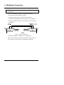
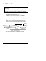
3. The Matrices
Throughout these instructions a stand alone Matrix can be considered as
a Master Matrix with no Slaves.
Each Master Matrix has 48 video inputs, 16 video outputs, 8 serial ports
for control of VCRs and multiplexers, a Centronics™ parallel printer
port, a network connector, a power connector and a screw-fitting earth
terminal.
A PY-32S (Slave Matrix) does not have serial or printer ports.
Figure 1. Matrix Connections (PY-48M16)
The Master/Slave feature allows a combination of up to 3 Slaves and a
single Master to behave as if they were one 144 video-input, 16 videooutput Matrix.
The purpose of a slave is to increase the number of video inputs into the
master matrix. To do this it must be situated adjacent to the master
matrix.
Page 7
4. Installation
If you are installing a single Matrix and not a Master/Slave system then
follow the instructions as if you were installing a Master with no Slaves.
Connecting a Master/Slave system consists of the following steps:
1) Change the jumper setting in the Slaves.
2) Connect the Video through the Slaves to the Master
3) Connect the Master/Slave interface cables (these are the control
cables - the Slave matrices do not connect to the Echelon network)
4) Connect the network
5) Use the installation tool to initialise the matrices
The instructions are given in the following sections
Page 8
4.1 Bar Coding
Each Master or Ordinary Matrix (not Slave matrices) is supplied with
two identical bar-codes. The bar code gives the unique 48-bit module
address.
Make a careful note on your module description sheet of all your
installation details and the location of the module. Then during
subsequent installation using the Windows™ Installation Tool the
bar-code module address and description can be entered.
The module address can also be obtained using the installation tool
utilities program by pressing the module address switch (figure 4). This
switch, which is included on every Pyramid module, forces the module
to broadcast its module address onto the network.
We recommend that during a system installation you store the module
description sheets in a ring-bound file. Keep them safe for referring to
when you are using the installation tool to configure the system.
4.2 Setting the Slaves using the Master/Slave links
Jumper settings are required to tell each Slave the order in which it is
connected
The Slave matrices are arranged in order. To decide the order read
section 4.4.
Note that the master/slave cable is short by design and cannot be
extended under any circumstances.
• Decide the order in which you want to connect your slaves. then see
Appendix A on page 20 to configure them.
Page 9
4.3 Connecting Video to an Single Matrix
All video connections must be via 75 ohm BNC connectors and video
coaxial cable.
Referring to Figure 1,
• Connect your cameras to video inputs 1 to 48.
• Connect video outputs 1 to 16 to your monitors or other equipment.
4.4 Connecting Video to a Master/Slave system
All video connections must be via 75 ohm BNC connectors and video
coaxial cable. The matrices should have been configured as their
relevant Slave numbers according to section 4.2.
On figure 6 each block represents 16 BNC to BNC connections.
Figure 2
You can connect 1, 2 or 3 slaves:
• Connect the slave 1 monitor outputs 1 to 16 to camera inputs 1 to 16
respectively on the master.
• Connect the slave 2 monitor outputs 1 to 16 to camera inputs 17 to 32
respectively on the master.
• Connect the slave 3 monitor outputs 1 to 16 to camera inputs 33 to 48
respectively on the master.
The outputs from the slaves must be connected in numeric order so that
they have a one to one correspondence with the inputs on the master, do
not change the numeric sequence.
Page 10
Note : The remaining inputs on the master can be used.
Note that the slaves are numbered first when it comes to selecting the
cameras (see the table below).
• Connect your video inputs to the video inputs on the slave and spare
video inputs on the master.
The numbering of the inputs for camera selection purposes varies
according to how many slaves are connected. The table below gives the
numbering
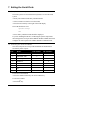
Table : Camera numbering for master/slave systems
Configuration
1st slave
2nd slave
3rd slave
Master only
Master
1 to 48
Master + 1 slave
1 to 48
49 to 80
Master + 2 slaves
1 to 48
49 to 96
Master + 3 slaves
1 to 48
49 to 96
97 to 112
97 to 144
none
4.5 Master/Slave control cable connection
If you are installing a single Matrix then go to the next section.
If you are installing a Master/Slave system then the next step is to
connect the matrices together using the control cable which is supplied
with each Slave.
• Connect the control cable from the M/S Interface on the Master
Matrix to serial port 3 on Slave#1
• Connect your Master and Slaves according to figure 7 using the cable
provided with each Slave Matrix.
SERIAL 5
SERIAL 5
SERIAL 5
M/S INTERFACE
SERIAL 7
Master
Slave #1
SERIAL 7
Slave #2
SERIAL 7
Slave #3
Figure 3. Slave Matrix Connection
Page 11
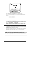
4.6 Connecting the Network
See Manual 2 - Network Wiring
The network plug provided has five terminals. Figure 8 shows the
network connections.
Figure 4. Network Connections
• Connect your Master Matrix to the network.
• Connect the cable screen to GND on pin 3.
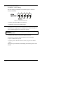
4.7 Switching on the Power
Each Matrix has a typical power consumption of 9 watts and requires a
class 2 isolated supply between 9V DC and 15V DC.
WARNING: Only use the power supply specifically provided by Baxall
for a Pyramid Matrix.
• Connect your matrices to the power supplies provided.
If your power is correctly connected then the power LED lights.
To power a Master/Slave system
• Connect power to the Slave matrices before you power the Master
Matrix
Upon power-up the monitors should display the following screen for 30
seconds:
Page 12
Note: The number following the V is the software version
After 30 seconds the Pyramid reverts to normal operating mode and
displays:
camera 1 on monitor 1,
camera 2 on monitor 2,
.
.
camera 16 on monitor 16.
If any cameras are not connected then the monitors will display Video
Loss {. . camera number . . .} in their place.
Monitor 1 displays the names of all the Video Loss Cameras in order.
4.8 Installing the Matrix using the Installation Tool
For the Matrix to operate in a Pyramid System it is necessary to use the
Installation Tool to ‘bind’ it to the network.
The process of binding informs each of the modules on the network of
the presence of the other modules so that they can work together.
More binding details are given in the Installation Tool instructions.
NOTE : If you change any of the alarm response settings or the
alarm input configuration you must re-bind all the receivers for them
to operate correctly.
Page 13
5. Multiplexer Connection
5.1 Baxall ZMX-9/16
CAUTION : Disconnect the power from all units before connecting
the serial ports.
To connect a ZMX-IT multiplexer to the Matrix Serial port:
• Wire the RS232 lead according to figure 9.
• Connect the female plug to a serial port on your Matrix
• Connect the Male plug to the RS232 connector on your ZMX-IT
• Connect the Monitor A BNC on your ZMX-IT to a video input on
your Matrix.
Figure 5. RS232 Lead Wiring
• Install your ZMX-IT according to its own instructions
Note: Keep a record of the connection numbers for future reference.
• See section 7 for detail on how to configure the serial ports.
Page 14
5.2 DM Uniplex / Vista Norplex
CAUTION : Disconnect the power from all units before connecting
the serial ports.
To connect a Uniplex/Norplex multiplexer to the Matrix Serial port :
• Wire the RS232 lead according to figure 10.
• Connect the female plug to a serial port on your Matrix
• Connect the Male plug to AUX3 on your Uniplex or Norplex
• Connect the Monitor A BNC on your multiplexer to a video input on
your Matrix
Figure 6. RS232 Lead Wiring
• Install your multiplexer according to its own instructions.
Note: Keep a record of the connection numbers for future reference.
• See section 7 for detail on how to configure the serial ports.
Page 15
6. VCR Connection
6.1 Mitsubishi 5600
CAUTION : Disconnect the power from all units before connecting
the serial ports.
CAUTION: These connections apply to the Mitsubishi 5600BRSA
VCRs. Earlier versions of Mitsubishi VCRs (e.g. 5600BRS ) may
require different connections. Contact technical support for advise.
To install a VCR on the Matrix serial port
• Wire the connecting lead according to figure 11.
• Connect the 9-way connector to a serial port on your Matrix
• Connect the 25-way connector to your VCR
• Connect a video source to your VCR and connect the output from
your VCR to a video input.
• Install your VCR according to the instructions provided with it
Note: Keep a record of the connection numbers for future reference.
Pyramid Matrix
Serial Port
Mitsubishi 5600 VCR
Link 5, 6 and 20
Rx Tx
13
12
25
11
24
10
23
9
22
8
21
7
20
Wiring Side
Male Plug
6
19
5
18
4
17
3
16
2
15
Rx
1
14
Cable
Screen
Signal GND
1
Tx
2
6
3
7
4
8
Wiring Side
Female Plug
Figure 7. RS232 Lead Wiring
• See section 7 for detail on how to configure the serial ports.
Page 16
5
9
7. Setting the Serial Ports
7.1 Setup in the menu system
The menu system is accessed from the keyboard. To access the menu
system:
• Insert your smartcard and enter your PIN number
• Select a monitor on which to view the menus
• Press the LIST UP key to the right of the LCD display
The LCD should now read:
System Setup?
Yes
• Press softkey 1and the menus should be displayed.
If you are installing the MUX or VCR using the system setup menus
then configure the serial port in the SERIAL PORT CONFIG menu and
configure the video inputs in the VIDEO SOURCE CONFIG menu.
7.2 Selecting the VCRs and MUXs
Once the serial ports are set-up VCRs and MUXs are numbered for
selection by order of ports:
Port
Device
VCR Number
MUX Number
1
Mitsubishi 5600
1
2
Mitsubishi 5600
2
3
DM Uniplex
1
4
ZMX9/16
2
5
n/c
6
Mitsubishi 5600
7
n/c
8
Mitsubishi 5600
3
3
To select a VCR or MUX:
• Press the number followed by the VCR or MUX key
To de-select a MUX
• Press the F key.
Page 17
8. Maintenance
Once your Matrix is correctly installed and commissioned it requires no
routine maintenance.
9. Technical Support
If need technical support for any reason then you should always have
the following information to hand.
• The instructions (scan through them and ensure you have not missed
anything.)
• The matrix software version number (see section 4.7 for how to
obtain this.)
• The keyboard software version number (displayed when you first
insert your smartcard).
• Any other information which may be relevant such as site plans,
module-description-sheets and the instructions for any associated
equipment.
A contact phone number should be provided in the Installer Details
section of the matrix menu system.
Page 18
10. Specifications
Features (PY-48M16-H, PY-48M16-L)
48 video inputs, 16 video outputs, 8 serial control ports,
printer port, power and network connectors
Bar-coding for ease of installation
On-screen menus for system setup
Control of VCRs and Multiplexers
Up to 3 Slave matrices giving 144 video inputs, 16 video outputs
Features (PY-32S)
Adds 32 video inputs to a master matrix.
Network
Optional FTT10 (PY-48M16-H), RS485 (PY-48M16-L, PY-48M16-2-H)
Video
Video 1V pk-pk composite via BNC connectors
Video loss alarm
Serial Ports
8 serial ports (RS232 9-pin male D-type) for control of VCRs and Multiplexers
Master/Slave interface port (cable supplied with PY-32S)
Printer port
Centronics parallel port. Printer port for logging / audit printing.
25 way female D-type (for standard PC printer cable)
Power
Supply 9V to 15V DC, 1A class 2 isolated
Consumption 9W (12V DC)
Physical
Weight : 4.5 kg
Dimensions : 483 x 178 x 42 mm (19”, 4U rack mounting)
Case : mild steel with access hinge, graphite grey with blue lettering
Temperature Specification
Operational temperature limits:-10ºC to +50ºC at 10% to 80% relative humidity (non-condensing)
Storage temperature limits:-20ºC to +60ºC at 10% to 95% relative humidity (non-condensing)
Page 19
Appendix A - Configuring your Slave Matrices
To configure Slave matrices, it is necessary to open your matrices and
define the slave number. The procedure is detailed below:
Note : This operation is best done before you connect the cables.
CAUTION : Take normal ESD (Electro-Static-Discharge) precautions
during this procedure to prevent damage to your Matrix.
• Ensure that your Matrix is switched off
• Remove the securing screws, keep the screws safe, (figure 2) and fold
down the hinged Matrix door (the top, as shown in figure 2, moves
towards you)
remove
screw
remove
screw
48M16
Figure A
• Arrange the jumpers in your Slave Matrix (see figure B for location)
according to figure C.
Master/Slave
Links
Figure B
Keep a record of which Matrix is which to save opening them at a later
date.
Master and
Slave #1
Slave #2
Slave #3
Figure C. Jumper settings in the master and slaves
• Close and fasten your matrices.
Page 20
NOTES
Page 21
NOTES
Page 22
NOTES
Page 23
Baxall Security Limited.
Stockport, England
Visit o u r Web site:
h ttp : //www.b a xa ll.co m
Baxall Security Ltd. Reserve the right to make changes to the product and
specification of the product without prior notice to the customer.
HBPY48M16-3
Issue 3 : 11/96