1
f
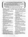
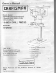
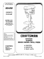
Save ThisManual
"_
I
For FutureReference
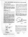
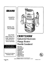
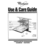
MODEL NO.
113.213090
DRILL PRESS WITH
MAXIMUM
DEVELOPED
1/2 HP MOTOR
Serial
Number
Model and
serial number
may be found at the rear of
the head.
You should record both
model and serial number in
a safe place for future use.
10-INCH
BENCH MODEL DRILL PRESS
• assembly
• operating
e repair parts
CAUTION:
READ ALL
iNSTRUCTIONS
CAREFULLY
",...
MOTORIZED
.j
Sold by SEARS, ROEBUCK AND CO., Chicago,
Part No. SP5t85
../
IL 60684
U.S.A.
Printed
in Taiwan
GENERAL SAFETY INSTRUCTIONS
1, KNOW YOUR POWER TOOL
Read and understand the owner's manual and
labels affixed to the tool Learn its application and
limitations as well as the specific potential hazards
peculiar to this tool.
2. GROUND ALL TOOLS
This tool is equipped with an approved 3-conductor
cord and a 3-prong grounding type plug to fit the
proper grounding type receptacle. The green conductor in the cord is the grounding w_re. Never
connect the green w_reto a live terminal.
3. KEEP GUARDS IN PLACE
In working order, and in proper adjustment and
alignment.
4. REMOVE ADJUSTING KEYS AND WRENCHES
Form a habit of checking to see that keys and
adjusting wrenches are removed from tool before
turning It on.
5. KEEP WORK AREA CLEAN
Cluttered areas and benches invite accidents. Floor
must not be slippery due to wax or sawdust.
6, AVOID DANGEROUS ENVIRONMENT
Don't use power tools in damp or wet locations or
expose them to rain. Keep work area well lighted,
Provide adequate surrounding work space.
7. KEEP CHILDREN AWAY
All visitors should be kep_ a safe distance from
work area
8. MAKE WORKSHOP CHILD-PROOF
With padlocks, master switches, by removing starter keys. or storing tools where children can't get
them.
13.
15.
16.
17.
18.
19.
FOR POWER TOOLS
Z87.1) at al! times. Everyday eyeglasses are not
safety glasses. They only have impact resistant
lenses Also. use face or dust mask if cutting operatior is dusty, and ear protectors (plugs or muffs)
during extended oeriods of operation.
SECURE WORK
Use c_arnps or a vise [o hold work when practical.
It frees both hands to operate tool.
DON'T OVERREACH
Keep proper footing and balance at all times.
MAINTAIN TOOLS WITH CARE
Keep tools sharp and clean for best and safest
performance. Follow instructions for lubricating and
changing accessories.
DISCONNECT TOOLS
Before servicing; when changing accessories such
as blaoes bits, cutters, etc.
AVOID ACCIDENTAL STARTING
Make sure switch is in "OFF" position before olugglng _n
USE RECOMMENDED ACCESSORIES
Consult the owner's manual for recommended accessor es Fo ow the
the accessories. The instructions that accompany
use of improper accessories
may cause hazard s,
NEVER STAND ON TOOL OR ITS STAND
Serious injury could occur if the tool is tipped or if
the cutting tool is accidentally contacted. Do not
store materials above or near the tool such that _t
is necessary to stand on the tool or _ts stand to
reach them
9. DON'T FORCE TOOL
It will do the job better and safer at the rate for
which it was designed.
10. USE RIGHT TOOL
Don't force tools or attachment to do a job it was
not designed for.
11. WEAR PROPER APPAREL
Do not wear loose cothing goves necktes, or
jewelry (rings wristwatchesito get c_Lught n moving p_trts. NONSLIP f0otwear S re ;ornmended
Wear protective ha r cover ng to conla n ong hair.
20. CHECK DAMAGED PARTS
Before further use of the tool. a guard or other part
that =s damaged should be carefully checked to
ensure that it will operate properly and perform its
=ntended functJon Check for alignment of moving
parts, b_nding or moving parts, breakage of parts.
mounting, and any other conditions that may affect
its operation. A guard or other part that is damaged
should be proper_y repaired or replaced.
21. DIRECTION OF FEED
Feed work nto a b ade or cutter aga nst the d rect on of rotation of the bade or cutter on y
Roll t(_ngsleeves above the elbow.
12. USESAFETYGOGGLES(HEADPR
:)TECTION)
Wear safety goggles (must _om'rp wth ANSi
22 NEVER LEAVETOOL RUNNING UNATTENDED
Turn power off Dont eave too unt t comes to a
compete stop.
2
additional safety instructions for drilm presses
2
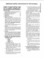
WARNING: FOR YOUR OWN SAFETY, DO NOT
ATTEMPT TO OPERATE YOUR DRILL PRESS
UNTIL iT iS COMPLETELY ASSEMBLED AND INSTALLED ACCORDING TO THE iNSTRUCTIONS...
AND UNTIL YOU HAVE READ AND UNDERSTAND
THE FOLLOWING:
1. General Safety instructions for Power Tools.
--
2
2. Getting to Know Your Drill Press ........
3. Basic Drill Press Operation .............
17
22
4. Adjustments ..........................
5. Maintenance ..........................
24
25
6. Stability of Drill Press
If there is any tendency of the drill press to tilt or
move during any use, bolt it to the floor or a flat
piece of 1/2" exterior plywood large enough to
stabilize the drill press. Bolt the plywood to the
underside of the Base. so it extends at least to
both sides. Make sure the plywood won't trip the
operator, Do not use pressed wood panels-they can break unexpectedly.
If the workpiece is too large to easily support with
one hand, provide an auxiliary support.
7. Location
Use the drill press in a well lit area and on a level
surface clean and smooth enough to reduce the
risk of trips, slips, or falls. Use it where neither the
operator nor a casual observer is forced to stand
in line with a potential kickback.
8. Kickback
A kickback occurs when the workpiece is suddenly
thrown in the OPPOSITE direction to the DIRECTION OF FEED: THIS CAN CAUSE SERIOUS INJURY. Kickbacks are most commonly caused by
use of accessories NOT recommended for this tool.
9. Protection: Eyes, Hands, Face, Ears and Body
WARNING: TO AVOID BEING PULLED INTO
THE SPINNING TOOL -1. Do NOT wear:
-- gloves
-- necktie
-- loose clothing
-- jewelry
2. Do tie back long hair
a. If any part of your drillpress is missing, malfunctioning, has been damaged or broken..,
such
as the motor switch, or other operating control,
a safety device or the power cord . . . cease
operating immediately until the particular part
is properly repaired or replaced.
b. Never place your fingers in a position where
they could contact the drilI or other cutting tool
if the workpiece should unexpectedly shift or
your hand should slip.
c. To avoid injury from parts thrown by the spring,
follow instructions exactly as given and shown
in adjusting spring tension of quill.
--
---
--
---
-
-
--
d: To prevent the workpiece from being
torn from your hands, spinning of the
toot. shattering the tool or being thrown,
always properly support your work so
it won't shift or bind on the tool:
Always position BACKUP MATERIAL (use
beneath the workpiece) to contact the left
side of the column.
Whenever possible, position the WORKPIECE to contact the left side of the column-if it is too short or the table is tilted,
clamp solidly to the table. Use table slots
or clamping ledge around the outside edge
of the table.
When using a drill press VICE, always fasten it to a table.
Never do any work "FREEHAND" (handholding workpiece rather than supporting it
on the table), except when polishing.
Securely lock Head and Support to Column,
and table to support before operating drill
press.
Never move the Head or Table while the
tool is running.
Before starting the operation, jog the motor
switch to make sure the drill or other cutting
tool does not wobble or cause vibration.
If a workpiece overhangs the table such
that it will fall or tip if not held, clamp it to
the table or provide auxiliary support.
Use fixtures for unusual operations to
adequately hold, guide and position workpiece.
Use the SPINDLE SPEED recommended
for the specific operation and workpiece
material--check
the inside of the Belt
Guard for drilling information; for accessories, refer to the instructions provided
with the accesso[ies.
f. Never climb on the drill press Table, it
could break or pull the entire drill press
down on you.
g. Turn the motor Switch Qff and put away
the Switch Key when leaving the drill
press.
h. To avoid injury from thrown work or tool
contact, do NOT perform layout, assembly, or setup work on the table while
the cutting tooI is rotating,
10. Use only accessories designed for this
drill press to avoid serious injury from
thrown broken parts or work pieces.
a. Holesaws must NEVER be operated on
this drill press at a speed greater than
400 RPM
.E
_
_"
"_
t,_
:_
-D
"._
13 Think Safety, Safety is a combination of operator
common sense and alertness at all times when the
drill press is being used.
WARNING: DO NOT ALLOW FAMILIARITY (GAINED
FROM FREQUENT USE OF YOUR DRILL PRESS)
TO BECOME COMMONPLACE.
ALWAYS REMEMBER THAT A CARELESS FRACTION OF A
SECOND iS SUFFICIENT TO iNFLICT SEVERE
INJURY,
b. DrumsandersmustNI
_ER be operated on
the drill press at a sp_ d greater than 1800
RPM.
o. Do not insta I or use an_
length or extends 6' b#lc
Cad suddenly bend out_
d Do not use wire whee s,
ters circle (fly) cutters €
drill press.
rill that exceeds 7" in
the chuck jaws. They
rd or break.
)uter bits, shaper cutrotary planers on this
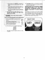
11. Note and Follow the Safety Warnings and Instructions that Appear on the Panel on the
Right Side of the Head:
o
o
I DANGER
J FOR YOUR
The operation of any power toot can result in foreign
objects being thrown into the eyes, which can result in
severe eye damage. Always wear safety goggles comply with ANSl Z87.1 (shown on Package) before comrnenc_ng 0ower tool operation. Safety Goggles are
available at Sears retail or catalog stores.
OWN SAFETY:
Know This Tool! Read and Understand
Owner's Manual before Using th=s
Machine, Use Recommended
Drill S_eedSee Chart inside Pulley Cover,
m Always
wear safety goggles
that comply
with
m Donotweargloves.necktieorlooseclothing
long hair.
m Securelyclampworktotableifitistooshort
the column
when in operatmg
position.
O
•
Securely lock head and support to Column.
to support, before operating drill press,
a
Use
only
recommended
accessories.
ANSI
Tieback
Z87.1
WEAR
SP=NO_E
YOUR
_N
tocontact
and table
_" ('U_
E82443
O
12. This Drill Press has 4 speeds as listed below:
48O RPM
930 RPM
1750 RPM
3000 RPM
i
See inside of guard for specific placement of belt
on pulleys.
4
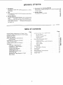
glossary
1. Workpiece
The item on which the cutting operations
is being
performed.
2. Drill
The cutting toot used in the dril_ press to make holes
in a workpiece.
of terms
4. Revolution
Per Minute
(R.P.M.)
The number of turns completed
by a spinning
in one minufe,
object
_=
O
5. Spindle Speed
The RPM of the spindle.
_"
3. Backup
Material
A piece of wood placed between the workpiece and
table ....
it prevents wood in the workpiece from
splintering
when the drill passes through the backside of the workpiece ....
also prevents drilling into
the table top.
table of contents
Page
17
.
19
20
2O
Page
General Safety Instructions
for Power Tools ......
Additional Safety Instructions
for Drill Presses
....
Glossary of Terms .......................
Table of Contents ..........................
Motor Specifications
and Electrical
Requirements
..........................
Unpacking and Checking Contents
.............
Table of Loose Parts ........................
Location and Function of Controls
.............
Assembly
................................
Assembly of Base/Column
...............
Installation of TabletSupport
..............
Installing the Head .....................
Installing Feed Handles
.................
Installing the Chuck .....................
Installing Belt Guard Knob
...............
Tensioning
Belt ........................
Adjusting the Table Square to Head
.......
Bevel Scale ...........................
2
3
5
5
6
7
8
9
10
10
10
13
14
14
15
15
I6
16
Getting
to Know You_
On-Off
Switch
Remownq
Dnlhng
Drdl
Press
..
The Chuck
Io Depth
......
Depth Sca_e
...........
Bas=c Drill Press Operation
Installing Drills
...........
Pos*honmg Table and VVorko_ece
T_thng Table
Hole hocatlon
Feeding
Adlus[rnenls
............
Qudl Relurn Sprtng.
.
Maintenance
............
Lubncat_on
......................
Recommended
Accessories
Trouble Shoot_ng
................
Repair Parts
..
...
.....
21
. 22
22 "_
23€_
23 "_
24
24 "_
24
24
25
25
25
26
27
i_i !i_i_i_i
_
motor spec Tca ons and electrica
ifi
requ
_ m
MOTOR SPECiFICATiONS
TNs dril! press is designed to use a 1725 RPM motor
only. Do not use any motor that runs faster than 1725
RPM It is wired for operation on 110-120 volts. 60 Hz.
alternating current,
WARNING: TO AVOID INJURY
FROM UNEXPECTED STARTUP, DO NOT USE BLOWER OR
WASHING MACHINE MOTORS OR ANY MOTOR
WITH AN AUTOMATIC RESET OVERLOAD PROTECTOR.
CONNECTING TO POWER
SOURCE OUTLET
This machine must begrounded while _nuse to protect
the operator from electric shock.
Plug power cord Into a 110-!20V properly grounded
type outlet protectea by a 15-amo dual element time
delay or Circuit breaker.
NOT ALL OUTLETS ARE PROPERLY GROUNDED.
IF YOU ARE NOT SURE THAT YOUR OUTLET, AS
PICTURED BELOW. iS PROPERLY GROUNDED,
HAVE IT CHECKED BY A QUALIFIED ELECTRiCiAN.
WARNING: TO AVOID ELECTRIC SHOCK. DO NOT
TOUCH THE METAL PRONGS ON THE PLUG,
WHEN INSTALLING OR REMOVING THE PLUG TO
OR FROM THE OUTLET.
°reme
t s i¸
This power tool is equipped with a 3-conductor
and grouna_ng type plug, approved by Underwriters'
Laooratories and the Canadian Standards Association:
The grouna conductor has a green jacket and is at_
tached to the tool housing at one end and to the grour]d
prong in the attachment plug at the other end.
This plug requires a mat ng 3-conductor grounded type
outlet as shown.
If the outlet you are planning to use for this power tool
s of the two prong type, DO NOT REMOVE OR ALTER
THE GROUNDING PRONG IN ANY MANNER. Use
an adapter as shown and always connect the grounding
tug to known ground.
It is recommended that you have a qualified electrician
replace the TWO prong outlet with a properly grounded
THREE orong outlet.
An adaoter as shown below is available for connecting
plugs to 2-pror_g receptacles.
WARNING: THE GREEN GROUNDING LUG EXTENDING FROM THE ADAPTER MUST BE CONNECTED TO A PERMANENT GROUND SUCH AS
TO A PROPERLY GROUNDED OUTLET BOX.
GROUNDING
SCREW
LUG
\
WARNING: FAILURETO PROPERLY GROUNDTHIS
POWER TOOL CAN CAUSE ELECTRICUTION OR
SERIOUSSHOCK, PARTICULARLY WHEN USED IN
DAMP LOCATIONS. OR NEAR METAL PLUMBING.
IF SHOCKED, YOUR REACTION COULD CAUSE
YOUR HANDS TO HIT THE CUTTING TOOL
IF POWER CORD IS WORN OR CUT, OR DAMAGED
IN ANY WAY, HAVE IT REPLACED IMMEDIATELY
TO AVOID SHOCK OR FIRE HAZARD.
ADAPTER
3-PRONG
PLUG
NOTE: The adapter illustrated is for use only if you
alreaoy nave a properly grounded 2-prong receptacle,
Adapter is not allowed in Canada by the Canadian Electrical Code.
\
GROUNDING
PRONG
The use of any extension cord will cause some loss of
0ower. To Keep this to a minimum and to prevent overneatmcj and motor bum-out, use the table below to
determine the minimum wire size (A W.G) extension
cord Use only 3 wire extension cords which have 3prong grounding type plugs and 3-pote receptacles
which accept the tools ptug.
Extension Cord Length
0-25Feet
26-50Feet
51-100 Feet
has a plug that looks
Wire Size A.W.G.
16
!4
12
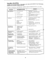
unpacking
and checking
WARNING:
TO AVOID
iNJURY
FROM
UNEXPECTED STARTING
OR ELECTRICAL
SHOCK, DO
NOT PLUG THE POWER CORD iNTO A SOURCE
OF POWER. THIS CORD MUST REMAIN
UNPLUGGED WHENEVER
YOU ARE WORKING
ON THE
DRILL PRESS.
Model 113.213090
one box.
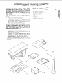
1. Unpacking
Drill Press
and Checking
a. Separate ali "loose
rials and check each
Parts" to make sure
before discarding any
is shipped
compiete
n
Contents
parts" from packaging mateitem with "Table of Loose
ali items are accounted
for
packing material
WARNING:
IF ANY PARTS ARE MISSING,
DO NOT
ATTEMPT TO ASSEMBLE
DRILL PRESS, PLUG IN
THE POWER CORD, OR TURN THE SWITCH ON
UNTIL THE MISSING PARTS ARE OBTAINED
AND
ARE INSTALLED
CORRECTLY.
2
3
Remove the protective oil that is apoliec to the
table and column. Use any ordinary hoLJsehold type
grease and spot remover.
WARNING:
TO AVOID FIRE OR TOXIC REACTION, NEVER
USE GASOLINE,
NAPTHA
OR
SIMILAR HIGHLY VOLATILE
SOLVENTS.
Apply a coat of paste wax to the tab!e and co!umn
to prevent rust. Wipe all parts thoroughly
with a clean
dry cloth.
G
E
TABLE
Item
contents
OF LOOSE
pARTS
Description
Qty.
A
_::
C
D
E
F
"
r, ,_,t Asrlr_....
Tae
e "Su_..pL
.............
Column
SL_pport As,q"_ ..................
Owners MamJa
...................
Box of Loose Parts
.................
Base .........
•
•
..............
Head A.....
,_
................
I_
_
"1
G
Bag of Loose Parts
i
...........
'
_
1
"_
_ "_
.E o
o c
t*_
=
L_
_,.,c _'
o
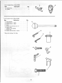
List of Loose Parts in Box 507884
item
Description
Chuck Key . ......................
Chuck ..............................
B
A
/
Qty.
1
1
List of Loose Parts in Bag 507885
item
C
D
E
*F
*G
H
I
*J
*K
Description
Feed Handle ........................
Wrench Hex "L" 3mm
................
Wrench Hex "L" 4mm ................
Knob .............................
Screw Pan Hd, M5 x 0.8-12
..........
Table Crank ........................
Support LOCKHandle .................
Switch Key ........................
Screw Hex Hd M8 x 1.25-20 ..........
Qty.
3
1
1
1
1
1
1
1
4
C
fD
7
F
These Parts Shown =ull Size
E
#
J
qJ
G....G ]'llltlrl,l,l'l'lt!'l'l'g (_
H
J
K
/
/
/
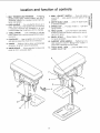
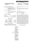
location and function
1, BELT TENSION LOCK HANDLES...
Tightening
handles locks motor bracket support and BELT
TENSION HANDLE to maintain correct belt distance and tension,
7. DRILL "ON-OFF"
SWITCH . . . Turns drift press
on and off . . , also used to lock drill press in off
position,
8. DEPTH SCALE LOCK
at selected position.
2. FEED HANDLE...
For moving the chuck up or
down, One or two of the handles may be removed
if necessary whenever
the workpiece
is of such
unusual shape that it interferes with the handles,
"5
scale
Provides
_
means tc ; ,_just quill
10. HEAD LOCKS...
Locks the head to the columr
ALWAYS have them locked in place while operazing the drill press.
11. BEVEL SCALE . •
for bevel operations.
4. CHUCK KEY...
Used to tighten drill in the chuck
and also to loosen the chuck for drill removal.
,
Shows
degree
tab_
s ÷_
,_ted
12. SUPPORT
LOCK HANDLE...
Tightening
locks
table support to column, Always" have it Iocke(_ tn
place while operating the Drill Press.
Holds drill bit or other recomrpended
to perform desired operations.
6. DEPTH SCALE...
Allows operator
press to drill to a desired depth.
Locks the depth
_
,_ o
.-J
9. SPRING CAP
spring tension,
3. TABLE
CRANK
. . . Turn clockwise
to elevate
table. Support lock must be released before operating crank,
5. CHUCK...
accessory
of controls
to adjust drill
13. TABLE
position
5
4
11
12
13
£
BEVEL LOCK...
from 0'_'-45 °.
Locks the table
in any
o
to
"
u,.
FRAMING SQUARE MUST BE TRUE,
-Check its accuracy
....
TOOLS
NEEDED
..............
as il;ustrated below,
DRAW LIGHT
LINE ON BOARD
STRAIGHT EDGE OF
BOARD 3/4" THICK-THIS EDGE MUST BE
ALONG THE EDGE ,_
PERFECTLY
SCREWDRIVER
STRAIGHT
_m
SQUARE
_J"
fl
_J
8-INCH ADJUSTABLE
WRENCH
SHOULD
SQUARE
BE NO GAP OR OVERLAP
WHEN
IF FLIPPED
OVER IN DOTTED
POSITION
JflllJltli!li JIl tlltllltlll
8mm DIA. x 20turn LONG BOLT
ASSEMBLY
OF BASE/COLUMN
COLUMN
ASSEMBLY
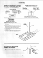
1 Position base on floor. Remove protect_vecoverlng
and discard
2, Remove protective sleeve from column tube and
discard. Place column assembly on base, and align
holes in column support with holes in base.
RACK
3. Locate four (4) 8ram Dia. x 20ram long bolts among
oose parts bag,
4, Install a bolt _n each hole through column support
and base and tighten with adjustable wrench.
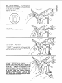
1, L_sen set screw n Column collar with 3ram HEX
wrenchand remove co ar and rack from co umn
COLUMN
COLLAR
10
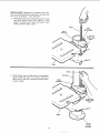
SPECIAL
NOTE: Make sure the elevation worm gear
shaft is extending through the opening in the table support as far as possible -- See Illustration.
2. With long smooth end of rack pointing upward, slide
rack down through large round opening in table
support.
Engage rack in gear mechanism
found
inside opening of table support.
RACK
GEAR
MECHANISM
TABLE
SUPPORT
ELEVATION
WORM GEAR
SHAFT
TABLE
RACK
COLt.
3. While hotding rack and table support in an engaged
position slide both down over column. Slide rack
down column until rack is positioned against lower
column support.
TABLE
ELEVATION
WORM GEAR
SHAFT
!
TABLE
11
LOWER
COLUMN
SUPPORT
COLUMN
COLLAR
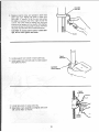
4. Replace column collar and position it bevel side
down over rack. Tighten set screw in collar with
3ram HEX "E' wrench. To let the rack slide when
the table is swung to the left or right around the
column, the collar must s_t loosely over rack aria
should not be angled on the column- Only tighten
set screw enough to keep collar _n ulace, otherwise
the collar may De broken due to excess pressure
CAUTION: To avoid co lumn tube or collar damage, do not over tighten set screw.
RACK
TABLE
5. Locate support
lock handle in loose 3arts bag.
SUPPORT_
6. Install support lock from left side into table support
and tighten by hand.
SUPPORT
LOCK HANDLE
TABLE
SUPPORT
7. Locate table crank in loose parts bag.
8. Install table crank assemb y and tighten set screw
with a 3turn HEX "E' wrench.
TABLE
CRANK
12
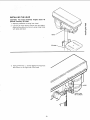
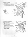
INSTALLING
THE HEAD
CAUTIONi
The head assembly
pounds. Carefully li_ head.
1. Remove
protective
covering
weighs
about
45
from head.
2. Carefully lift head above column tube and slide it
down on the column as far as it will go. Align head
with table and base.
i
HEAD
COLUMN
3.
Using a 4mm Hex 'L" wrench tighten the head lock
set screws on the right side of the head
..J
HEAD
HEAD
LOCK
SET SCREWS
13
FEED
HANDLE
HUB
!NSTALL{NG
FEED
HANDLES
!
Lecate th_-ee _3i feed handl_-s amor; 9 io0se pa,*ls.
2
S(_w
_ie feed ha:nd_es tight!y i_to 1he threaded
_ht hub
INSTALUNG
2
THE
CHUCK
_ocale the chuck among loose parts
CIear: out the TAPERED HOLE in the chuck: clean
the spindle nose with a clean cloth. Make sure
the_e are no foreign partic}es sticking to the surfaces The slightest piece of dirt on the spindle
nose or _n the chuck wi_ prevent the chuck from
seating
proper!y
THis w;_ cause the drill to
X,vobbte '
NOTE:
tremeIy
do_h
\
_f TAPERED HOLE in the chuck iS exdirty, use a c_eamng so_vent on the clean
CHUCK
•:_ Push the cr]_Jc:Kup on lhe spindle
,t w_t go
clockwise
nose ;As fa
and open
jaws
as
4
]urn cm_ck sleeve
chuck Cornpietely
_n
5
L_gntb! lap the nose of the chuck w_th a _ece of
woeo _o _nsure r_roper seating of the d]uck on the
spindle.
SPINDLE
J
NOSE
CHUCK
14.
BELT
5rr_m DiA
x !2ram
PAN
LONG
GUARD
KNOB
NO. SCREW
SCREW
BELT
GUARD
INSTALUNG
KNOB
BELT
GUARD
KNOB
1
To attach belt guard k:ob !ocate knob ar'd 5ram
Oa × 12ram ong par] hd screw _ loose parts
bag _nstalJ sc_ew n hoe ocated _n guarc and ab
taCh knob t_rnmg ;_;1_ l/ghl
WARNING:
TO AVOID
POSSIBLE
INJURY
KEEP
GUARD
1N PLACE
AND _N PROPER
WORKtNG
ORDER WHILE OPERATING.
TENSIONING
BEt.T
TENSION
LOCK
HANDLE
BELT
NOTE: T,__ Dr_ll P,ess s :m_pped w_ff: th(? bet _r_St,:_Jied
but _t shoud be pro;beriy t_.'m,oq_-,'dbefor÷, Js(,_
!
2
i.lfl (juard f[orn qghl s,;xe apt! e:-_v(' Op!}nei on
hinge
Looser
Be!t Te,%on
Lock Hand!es !ocaled on
BOTH SIDES of 0_1t P_es;head
P}il the motor
toward flont of @! pzess to r{:,_eve tens;o _on t}elt
BELT
TENSION
HANDLE
3
Choose speed for drii!ing operation, and move belt
to correct position for desired speed
NOTE: Refer to chart _nside belt guard
mended Drilfing Speeds
for Recom-
!5
4 _._ove
the_d.1orrearwarotoaop_yte_ls_on
tothe
5. TightenBeetTensionLOCk
Handles
NOTE:Be_,t
SHOULDdeflectapprox_matew
I/2'_ by
thuntb pressure
at mid-point
of be_t between
pulleys.
6 C_ose De_1[guard.
7
_ be_t s_[_£ ,*rhine drfihng, readjust
belt tension.
BELT
LOCK HANDLE
ADJUSTING
HEAD
THE
TABLE
SQUARE
TO
NOTE: The comb_nahon square rT1USt[3_ "_"Uf_
Unpack_n_
and Checking
Contents
section
mettled
See
to_
•
b_sert orec_s_on round steel
_ong rote chuck and tighten
rod approxlnqatel',i
2
With table raised to working height aria locked on
CO_LJrT'_n.
p_ace combmatlon square flat on table Deside rod
3
_f an adjustment _snecessary _oesen tl_e set screw
under bevetIock w_th 3ram "L wrench then loosen
the table bevel IoCk bolt with an adj LJstan_ewrench
(Th_s adjustmen,, _s located unaer the tablel
4
Ahgn the table square to the rod by relating table
unt_] the square arid rod are n I_ne
5
Ret_ghten table beve
6
Retighten
PRECISION
ROD
3
TABLE
BEVEL
LOCK
lock
set screw
SCREW
BEVEL
TABLE
SCALE
NOTE: The beve! scale t_as been included to Drowae
a qu_ck method for bevehng the table to approximate
angIes, tt precise accuracy ts necessary, a square, or
o_hef prec|s}on measuring tool should be used to posehen the table
1 To use {he bevel scale do the loltow ng
a. Loosen set screw and table beve! lock,see
3 above_
POINTER
steo
b
Move table so desired angle on beve sea e s
straigh_ across from zero line on table
c
Ret_g_en
SCALE
TABLE
table beve_ tock ana se_ screw
16
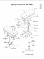
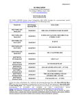
getting
knOW
to
your
driSl press
O
o3
o_
0
.F5
1
BELT
GUARD
22
FEED
HANDLE
2
BELT
TENSION
HANDLE
21
DEPTH
SCALE
LOCK
3
2O
COLUMN
DEPTH
SCALE
COLLAR
19
4
DEPTH
iNDiCATOR
FEED SPRING
ADJ USTME NT
rABLE
SUPPORT
18
TABLE
FEED
SPRING
5
TABLE
CRANK
6
17
RACK
COLUMN
7
COLUMN
8
16
15
HEAD LOCK
SCREWS
ON-OFF
SET
BASE
SWITCH
{_ ,,,/
14
SPRING
SPLINES
(GROOVES)
CAP
fJ_L,_-"'-_ SP,NDL
E
11
TABLE
13
SUPPORT
LOCK
HANDLE
BEVEL
LOCK
_
U
!2
BEVEL
(TEETH)
SCALE
CHUCK
10
CHUCK
KEY
QUILL AND SPINDLE
iNSiDE OF DRILL
17
ASSEMBLY
PRESS
SUPPORT
LOCK
SPINDLE[
This Drill Press has 4 speeds as listed below:
480 RPM
930RPM
1750 RPM
3000 RPM
See inside of belt guard for soecific placement of belts
on pulleys.
SPEEDS
IN
R.P.M.
480
930
1750
3OOO
and belt dunng
13
2. BELT TENSION LOCK HANDLE...
Tightening
handle locks motor bracket support to maintain c0rrect belt dtstance and tension
SUPPORT LOCK . . . T ghtentng locks tabe support to column. Always have _tlocked _nplace whde
operating the Unll Press
14
SPRING CAP
spring tension
15
HEAD LOCK SET SCREWS...
Locks the head
to the column ALWAYS have them locked tn place
wh_le operating tne drill press,
16
ON-OFF
SWITCH ... Has locking feature THIS
FEATURE
IS INTENDED
TO PREVENT
UNAUTHORIZED
AND POSSIBLE
HAZARDOUS
USE
BY CHILDREN
AND OTHERS
_7
COLUMN..
a one-piece
ment
18
TABLE .
workplece
!9
DEPTH SCALE iNDICATOR...
oepth selected on deoth scale.
!
BELT GUARD...
Covers
operation of drill press
pulleys
3. COLUMN COLLAR...
Holds tne rack lo the co_umn
Rack remains movable in collar to permit
table support movement.
4
TABLE
table
SUPPORT...
Rides on column
to support
5. TABLE
CRANK . _ . Turn ClOCKWiSe [O elevate
table. Support lock handle must be released before
operating crank
6. RACK...
Combines with gear mechanism to provide easy elevatton of table by hand operated table
Crank
7
COLUMN
SUPPORT...
Supports column
provides mounting holes for column to base
8
BASE...
Supports Drill Press. F:or addihonat stability: holes are provided in base to bolt Drill Press
to bench {See "Additional
Safety Instruchons for
Drill Presses.'h
9. CHUCK
accessory
,.,
1o perform
TABLE
position
...
Locks
the table m any
12. BEVEL
SCALE...
Shows degree table Js hlted
for bevel operations.
Scale _s moun_eo on table
suoport. It is to be used for qu_ck reference where
accuracy is not critical
18
means
working
to adjust qudt
surface
Locks
to support
Indicates
_ _ . Shows depth
and milhmeters
21, DEPTH SCALE LOCK...
to selected ae ptn
It is a self-electing
chuck key
out of the chuck when you let go
is designed to help prevent throwkey from the chuck wnen power
Do not use any other key as a
a new one d damaged or lost
BEVEL LOCK
from 0 -45.
. Prowaes
SCALE
drdled in mcnes
desired operations.
Provides
Coqnec[s head, table, and base on
tube for easy alignment
and move-
20 DEPTH
Holds anll bit or other recommended
10. CHUCK KEY...
which wtll "'pop"
of it. This action
mg of the chuck
_s turned "ON,
substitute, oraer
11
and
...
drilling
of hole being
the depth scale
22
FEED HANDLE
. . . For mov=ng the chuck up or
aown One or two of the handles may be removed
if necessary whenever
the workpiece Js of such
unusual shade that _t interferes with the handles
23
BELT TENSION
Bett "
24
DRILLING SPEED...
Can be changed by placing
the belt n any of the STEPS [grooves!
_n the pulleys See Spindle Speed chart _nside belt guard,
.
. Refer
to sechon
Tensioning
DRILL "ON-OFF" SWITCH . .. Has Iocmng feature
THIS FEATURE tS XITENDED TO HELP PREVENT
UNAUTHORIZED AND POSSIBLE HAZARDOUS USE
BY CHILDREN AND OTHERS
€.J
L, U . =::::
O
&
c_
Insert KEY into swftch
NOTE:
Key
_s made of yellow
plastic.
/
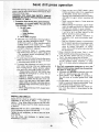
To turn drill ON . . .
Insert finger under switch
To turn drill OFF,
lever and pull.
. . Push lever in,
In an emergency;,
. . the drill bit BINDS.,
, STALLS
. . . STOPS . . . or tends to tear the workpiece loose
• .. you can QUICKLY turn the drill OFF by hitting the
switch with the palm of your hand.
To lock switch in OFF position , , . hold switch
one hand ... REMOVE key with other hand,
IN with
WARNING:
FOR YOUR OWN SAFETY,
ALWAYS
LOCK THE SWITCH "OFF" WHEN DRILL PRESS IS
NOT IN USE . .. REMOVE KEY AND KEEP IT IN A
SAFE PLACE ...
ALSO...
iN THE EVENT OF A
POWER FAILURE (ALL OF YOUR LIGHTS GO OUT)
OR
BLOWN
FUSE
OR
TRIPPED
CIRCUIT
BREAKER,
TURN SWITCH OFF . . . LOCK IT AND
REMOVE
THE KEY. THSS WILL PREVENT
THE
DRILL PRESS FROM STARTING
UP AGAIN WHEN
THE POWER COMES BACK ON.
19
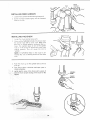
REMOVING
1
THE CHUCK
Open jaws of chuck
turning chuck sleeve,
as wide
as they w_lt go by
2. Carefully tap chuck w_th mallet
holding other hand under chuck
_t falls. It may be necessary to
several different spots around the
n one hand while
to catch _t when
lap tlqe crluck at
top of the chuck.
SLEEVE_
CHUCK_
CHU(
BODY
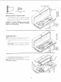
DRILLING
TO A SPECIFIC
DEPTH
To drill a BLIND hole (not all the way through) to a
given depth, proceed as follows.
1. Mark the depth of the hoe on the s de of the workpiece.
•
2. Loosen the depth scale lock.
3. With the switch OFF bring the dri!l down until the
TIP or lids of the dril are even with the Mark
DEPTH SCALE"
LOCK
4. Turn the depth scale counterclockwise until it stops
moving.
DEPTH
SCALE
5. Tighten the depth scale lock.
6. The drill will now be stopped at this depth until the
deoth scale is readjusted,
2O
ANOTHER
WAY
--
DEPTH
SC/_LE
1. With the switch OFF, loosen the depth scale lock.
2. Turn the depth scale clOCkWiSe until the depth scale
indicator points to the desired drilling depth on the
depth scale.
3. Tighten
DEPTH SCALE
LOCK
DEPTH
SCALE
the depth scale lock.
4. The chuck or drill will now be stopped after travefing
downward
the distance
selected
on the depth
scale,
LOCKING
CHUCK
DESIRED
1. With the switch off--loosen
DEPTH SCALE
INDICATOR
DEPTH
the depth scale lock.
2. Turn the feed handles until the chuck is at the
desired depth, Hold feed handles at this position.
3. Turn the depth scale
4. Tighten
clockwise
DEPTH
SCALE LOCK
until it stops.
the depth scale lock.
5. The chuck will now be held at this depth when the
feed handles are released.
SCALE
21
has c dr=l| press operation
i
•
Follow the following instructions for operating your drill
-
tool is running.
Before starting the operation, log the motor
switch to make sure the drill or other cutting
tool 0oes not wobble or cause vibration.
-- If a workpiece overhangs the table such that
it will fall or tip if not held, clamp it to the
table or provide auxiliary support.
- Use fixtures
for unusual
operations
to
adequately
hold. guide and position workpiece.
Use the SPINDLE
SPEED recommended
for the specific operation and workpiece material-check
the panel inside the guard
cover for drilling
information:
for accessories, refer to the instructions provided with
the accessones.
f. Never climb on tlqe drill press Table, it could
break or pull the entire drill press down on you,
g, Turn the motor Switch Off and put away the
Switch Key when _eaving the dri_t press.
h To avoid injur_ from thrown work or tool contact,
do NOT perform
iayout, assembly,
or setup
work on the table while the cutting tool is rotating.
2. Use only accessories
designed
for this drill
press to avoid serious
injury from thrown broken parts or work pieces.
a. Holesaws must NEVER be operated on this drill
press at a speed greater than 400 RPM,
b Drum sanders must NEVER be operated on
this drill press at a speed greater than 1800
RPM,
WARNING: TO AVOID BEING PULLED iNTO
THE SPINNING TOOL --
--
1. Do NOT wear:
-- gloves
-- necktie
-- loose clothing
-- jewelry
2, Do tie back long hair
a. It any part of your drill press is mtssing,.maffunctioning, has Peon damaged or broken.,
such
as the motor switch, or other operating control,
a safety device or the power coro.,
cease
operating immediately until the oarticutar part
is properly repaired or replaced.
b. Never place your fingers in a position where
they could contact the drill or other cutting tool
if the workpiece should unexpectedly shift or
your hand should slip.
c. To avoid injury from oarts thrown by the spnng,
tollow instructionsexactly as g_ven and shown
in adjusting spring tension of ouitl.
d. To prevent the workp_ece from being torn from
your hands, spinning of the too!. shattering the
tool or being thrown always properly support
your work so it won't shift or bind on the tool:
-- Always position BACKUP MATERIAL (use
beneath the workpiece) to contact the left
side of the column.
-- Whenever possible, position the WORKPIECE to contact the left side of the column-if it is too short or the table is tilte_
clamp solidly to the table. Use table slots or
clamping ledge around the outside edge of
the table.
-- When using a drill press VICE. always fasten
it to a table.
INSTALLING
Never do any work "FREE HAND" (handholding workpiece rather than supporting it
on the table), except when polishing_
Securely lock Head and Support to Column,
and table to support before operating drill
press.
Never move the Head or Table while the
c. Do not install or use any drill that exceeds 7" in
length or extends 6" below the chuck jaws. They
can suddenly bend outward or break.
d. Do not use wire wheels, router bits, shaper cutters, circle (fly) cutters or rotary planers on the
drill press.
DRILLS
Insert dri{_ into chuck far enough to obtain
GRIPPING of the CHUCK JAWS
. . the
approx. 1" long. When using a small drill do
it so far that the jaws touch the flutes (spiral
of thedrilL
Make sure that the drill is CENTERED
maximum
jaws are
not insert
grooves)
CHUCK
,n the chuck
22
KEY
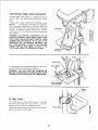
POSITIONING
TABLE
AND WORKPiECE
Lock the table to the column in a position so that the
tip of the drill is just a little above the top of the workpiece.
Always place a piece of BACK-UP MATERIAL (wood,
plywood . . .) on the table underneath
the workpiece.
This will prevent "splintering"
or making a heavy burr
on the underside on the workpiece as the drill breaks
through. To keep the backup material from spinning
out of control, it must contact the left side of the column,
as illustrated,
WORKPIECE
WARNING:
TO PREVENT
WORKPIECE
OR THE
BACKUP
MATERIAL
FROM BEING TORN FROM
YOUR HAND WHILE DRILLING,
POSITION
THEM
AGAINST THE LEFT SIDE OF THE COLUMN. IF THE
WORKPIECE
OR THE BACKUP
MATERIAL
ARE
NOT LONG ENOUGH
TO REACH THE COLUMN,
CLAMP THEM TO THE TABLE.
FAILURE
TO DO
THIS COULD RESULT IN PERSONAL
INJURY.
BAC K-U P..-"-_
MATERIAL
WORKPIECE.
DRILL PRESS X
For small pieces that cannot be clamped to the table,
use a drill press vise (Optional accessory),
VISE
WARNING:
THE VICE MUST BE CLAMPED
OR
BOLTED TO THE TABLE TO AVOID INJURY FROM
SPINNING WORK AND VISE OR TOOL BREAKAGE.
BOLT OR CLAMP
VICE SECURELY
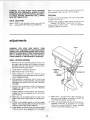
BEVEL
LOCK
TILTING
TABLE
To use the table in a bevel (tilted) position, loosen the
set screw under table bevel lock with Hex 'L" wrench.
Loosen beret lock with an adjustable wrench.
Tilt table to desired angle by reading
tighten bevel lock and set screw.
bevel scale.
J_
BEVEL SCALE
Re-
I::
SET SCREW
23
p-
WARNING:TO AVOID
INJURY FROM SPINNING
WORK OR'TOOL BREAKAGE, ALWAYS CLAMP
WORKPIECE AND BACKUP MATERIAL SECURELY
TO TABLE BEFORE OPERATING DRILL PRESS
WITH THE TABL E TILTED.
Before urnmg the switch ON, bring the drill down to
the workpiece lining it up with the hole location.
HOLE
to allow the drill to cut.
Feeding TOO SLOWLY might cause the.drill to burn
Feeding TOO RAPIDLY might stop the motor. , .
cause the belt or drill to SLIP . , . tear the workp_ece
LOOSE or BREAK the drill bit.
FEEDING
Pull down on the feed handles with only enough effort
LOCATION
Make a DENT in the workp_ece where you want the
hole.., usingaCENTERPUNCHoraSHARPNAIL,
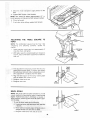
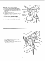
adjustments
BOSS
WARNING: FOR YOUR OWN SAFETY TURN
SWITCH "OFF" AND REMOVE PLUG FROM POWER
SOURCE OUTLET BEFORE MAKING ANY ADJUSTMENTS. TO AVOID INJURY FROM THROWN PA RTS
DUE TO SPRING RELEASE, FOLLOW INSTRUCTIONS CAREFULLY AND WEAR EYE GOGGLES,
QUILL
RETURN
SPRING
1. With the chuck at its highest possible position, turn
the depth scale clockwise until it stops and tighten
the depth scale lock, This wilt prevent the Quill dropping while tensioning the spring.
2. Lower table for additional clearance.
,NOTCH
STAND_
NUT
3, Work from left side of Ddtl Press,
(INNER)
4. Place screwdriver
ir lower front notch of spring
cap, ancl hold it in place while loose n ing and removfng jam [outer]
nut only.
CAP
JAM
(OUTER)
5. With screwdriver
remaining in notch. _oosen large
standard [inner] nut (approximately
1/8") until notch
disengages from boss on head. DO NOT REMOVE
THIS NUT
6. Carefully turn screwanver
counter clockwise and
engage next notch in boss. DO NOT REMOVE
SCREWDRIVER
7_ Tighten stanclarc nut with wrenci_ only enough to
engage boss. Do not overttghten as this will restrict
quill movement.
8. Move stop nuts and depth pointer to upper most
posit_on ant check tension while turmng feed handles.
11.
9. If there is not enough tenson
on spr ng repeat
steps 4-8 moving on y ONE notch each time and
checking tension after EACH repetition.
12. Check quill while feeding to have smooth and unrestricted
movement,
if movement
is too tight,
loosen jam nut and SLIGHTLY
loosen standard
nut until unrestricted,
Retighten jam nut.
t0.
Propertens on s ach eyed when quil returns gent y
to full up position when released from 3/4' depth.
24
When there is enough tension after checking,
replace .am nut and tighten to standard nut, BUT do
not overhghten against standard nut.
maintenance
)WARNING
FOR YOUR OWN SAFETY,
TURN
SWITCH "OFF" AND REMOVE PLUG FROM POWER
SOURCE OUTLET BEFORE MAiNTAINiNG OR LUBRICATING YOUR DRILL PRESS.
Frequently blow out any dust that may accumulate inside the motor.
A coat of furniture-type paste wax applied to the tab}e
and column wilt help to keep the surfaces clean.
WARNING: TO AVOID SHOCK OR F1RE HAZARD,
iF THE POWER CORD iS WORN OR CUT, OR DAMAGED iN ANY WAY, HAVE iT REPLACED IMMEDIATELY.
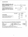
Wiri._g Diagram
=_
SPINDLE
ASSEMBLY
OF DRILL PRESS
lubrication
_1
SPINDLE
j 1[----._
RACK
All of the BALL BEARINGS are packed with grease at
the factory. They require no further lubrication.
(TEETH)
Periodically lubricate the SPLINES (grooves) in the
spindle, and the RACK (teeth of the quill).
.o_
.J
o"a
O
Sears Recommends
Drill Bits .........................
Hold-Down and Guide ..................
Drill Press Vises ...................
5 pc. Stop Collar Set ...............
Sanding Drums ................
the Following
See Catalog
9-2457
See Catalog
See Catalog
9-2497 -- 9-2498
Sears may recommend other accessories
o_
Accessories
15 Piece Drum Sanding Kit ..........
Clamping Kit ......................
Buffing Wheels up to 4" dia. max ......
Power Tool Know-How Handbook ........
See Catalog
See Catalog
See Catalog
9-29117
-g
E
E
o
not listed in the manual.
See your nearest Sears store or Catalog department for other accessories,
Do not use any accessory unless you have received and read complete instructions for its use.
25
trouble
WARNING:
SOURCE
shooting
FOR YOUR OWN SAFETY,
OUTLET
® CONSULT
BEFORE
TROUBLE
YOUR LOCAL SEARS
,
"OFF"
SERVICE
CENTER
IF FOR ANY REASON
CAUSE
1
tnc0rrect bett tension,
2
DrySpindte,
3
Loose spindle pulley,
!.
Incorrect speed•
2
Chips not coming out
of hole
Dul! Drill,
Feedingtoo slow,
Not lubricated
3
4
5
i
Drill leads off...
ho!e not round.
PLUG
FROM POWER
MOTOR
WILL
NOT RUN
1. Adjusttension.
See section
"ASSEMBLY --TENSIONING
BELT"
2. Lubricate spindle See "Lubrication"
section.
3. Checking tightness of retaining nut on
pulley, and bghten if necessary,
4, Tighten setscrews m pulleys.
4. Loose motor pulley
DrillBurns
REMOVE
REMEDY
I
=
NOisy Operation
AND ALWAYS
SHOOTING.
PROBABLE
TROUBLE
j_
TURN SWITCH
1. Change speed See section 'Getting
To Know Your Drill Press".
DRILLING SPEED•
2 Retract drill frquently to clear chips
3. Resharpen drilt.
4. Feed fast enough
allow drill to cut.
5. Lubricate drill• See "Basic Drill Press
Operation" section.
1. Resharpen
1, Hard grain_n woodor
lengths of cutting
lips and/or angtes
not equal.
2. Bentdrill bit.
drillcorrectly.
2. Replace drill bit.
1. Use"back-up
material"..
See Basic
Drill Press Operation" section.
Wood splinters on
underside,
t,
Workpiece
torn
toose from hand,
1. Not supported or
clamped properly,
I.
DriIi Binds in
1, workpiece pinchin_ri!i
or excessive feed pressure.
2 Improper belt tension.
t.
Excessive drill
runout or wobble,
I. Bent drill:
2. Worn spindle bearings,
3, Drill notproperly
installed in chuck.
4.. Chuck notproperly installed.
1, Use a straight drill.
2. Reptace bearings.
3. Install drill properly•..
See "Basic
Drill Press Operation" section.
4. Install chuck properly..,
refer to
"Unpacking and Assembly Instructions
... INSTALLING THE CHUCK."
Quill Returns
too slow or too
fast,
1. Spring has improper tension,
1. Adjust spring tension...
See section.
"Adjustments--Quill
Return Spring."
1. Dirty. grease, or oil on the
tapered inside surface of chuck*
or on the spindles tapered
surface.
1. Using a household detergent-clean
the
tapered surface of the chuck and spindle to
remove a!Idirt, grease and oit.
workpiece.
Chuck will not stay
attached to spindle
it falls off when
trying to install it,
NO "back-up material"
under workpiece.
Supportworkpiece
or clampit..
See
"Basic Drill Press Operation" section.
Supportworkpiece
orclamp it... See
"Basic Drill Press Operation" section.
2. Adjust tension..,
See section
"ASSEMBLY--TENSIONING
BELT."
t
26
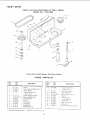
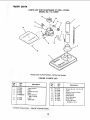
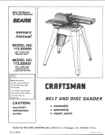
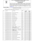
repair parts
PARTS
UST
FOR CRAFTSMAN
10" DR_LL
MODEL
NO. 113,213090
I
PRESS
3
2
4
/
19
14
Always
order
by Part Number--Not
FIGURE
Description
i
No.
1
2
3
4
817325
816755G
817587
817391- !
5
6
7
8
8! 7779q
STD3152 t 5
817605
817340-1
81 73391
8t 7606
817413
8! 7453
11
12
" Standard
Hardware
,,
i
LIST
..-TT--q
Key i
No. I
Part
Key
No.
uJ
1 PARTS
by Key Number
Part
No,
Description
i
Knob
Screw-Pan Hd M5 x 0 8-12
PutIey Motor
Screw-Hex Soc Set
M6xl
0-!0
Guard-Pu_iey w/Labels
* Bearing-Ba!} t 2ram
S aft-Spindle
Chuck
Key-Chuck
Tube-Qu_
Gasket-Quilt
RmgoRetainmg
item
--
May
Be
Purr.::hased
Loca
_'
14
t5
!6
17
18
19
2O
21
22
23
y
27
817358-2
817451
817483_1
STD31523_
817408
817407
817586
817440
817428
802864
816755-1
1
Screw-Wash
Fd
M6× _0 _ 12
Bush_ngoRubber
Ring Reta_!ir_g
'_BearJng-Bal 17ram
Spacer
Ir_sert-Puiley
Pulley-Spindle
Nut-Pul ey
Be}t-W" 5,'16 × 30
Ciamp Cord
Screw-Par- Hd M5 x (i, 8-i0
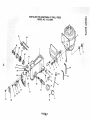
PARTS
LIST FOR CRAFTSMAN 10" DRILL PRESS
MODEL NO. 113.213090
=O
;:3.
O')
37
38
33
\
35
4
36
12
31
\
29
_
2O
\
24
\
26
4O
8
30
27
7
4
3
25
\
21
1
19
27
17
28
FIGU_2
39
3
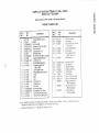
PARTS LIST FOR CRAFTSMAN
MODEL
NO.
10" DRILL PRESS
113.213090
O
Always order by Part Number--Not
FIGURE
2 PARTS
by Key Number
LIST
"O
fl#
_'_
Part
No.
I
2
1817610
I
I
I
I
1
4
5
6
7
8
t
!
I
t
I
Pa_
Description
Head w/Pointer & Trim
eMotor
*Nut-HexM8
* Washer 5/16 x 7/8 x 5/64
* NuFHex M!0
* Lockwasher- 7/16
Bracket-Motor
Screw-Hex Hd. M8x 1.25-2C
Support-Motor Bracket
Pin-Roll 6x 16
I 3 t ST0840812
STD5,51()37
STD841015
STD551143
817607
STD835025
t 9 1817596
f,o
I
t
I
I
10
11
!2
13
i15
] 16
t 17
I 18
t t9
j20
I 2t
t 22
123
[_
I 813249-152
I 817421
I 817391"2
{ 817343
1817439
I 817582
I 817485
I 8t3249-!28
I 817603
1817303
t STD375008
_ $7D852005
1816755-4
816755-3
Knob -Motor Adjusting
Screw-Hex Soc. Set
M8x 1,25-8
LOck-Depth Screw
Ring-Depth Stop w/Scale
Knob
Rod
Hub
Pin-Rolt5 x 16
Shaft-Pinion
Pin-Stop
*Connector-Wire
* Lockwasher-Ext.
5mm
Screw-Pan Hd. M5 x 0.8-8
Screw-Pan Hd. M5 x 08-12
25
26
27
816113
815863
817357
28
29
30
817585
817597
817594
31
817593
34
33
35
36
37
38
39
40
--
817595
STD541150
817415
817443
817329-1
71252
8133!7-6
8133!7-7
507885
507884
--
SP5185
® Any Attempt to Repair This Motor May Create a Hazard U{,,less Repair
Technician. Repair Service is Available at Your Nearest Sears Store
* SIandard
Hardware
Item -
May Be Purchased
L0cafiy
Description
Switch-Locking
Key-Switch
Screw-Self Tap, Parr Hd
M4x 16-8
Cover-Switch Piate
Box-Switch
Screw-Specia_ Set
M8x125x!8
Seat-Spring
*Nut-Hex 1/2-20
Cap-Spring
Spring-Torsion
Retainer-Spring
Cord-Power
i
Cord-Motor
I
Hex 'L'-Wrench
3ram
Hex "L '-Wrench 4ram
Bag of Loose Parts
(Not tflustrated)
Box of Loose ::ads
(Not l_tustrated)
I
Owners Manua_
(Not tiiustrated)
_s Done by QJa;,'ied
Service
¢e
PARTS
LIST FOR CRAFTSMAN
10" DRILL
MODEL NO, 113.213090
PRESS
1
10
\16
Always
order
by Part Number--Not
FIGURE
No.
i
u
817599
817601
817600
817609
5TD835020
6
817348
Tube-Column
Rack
Support*Column
Base
Screw-Hex Hd
M8 x 1,25-20
Crank
817590
Shaft-Gear
i
..
* Standard
Hardware
Part
No.
i
1
2
3
4
5
8
LIST
Key
No.
Description
No,
....
3 PARTS
by Key Number
,
9
10
11
12
13
14
15
16
,
Item -- May Be Purchased
Locally
3O
817447
817608
817772
817290
817589
817591
817592
817391-1
Description
i
Screw-Hex Hd 1/2-12 x 7/8
Table
Support-Table
w/Scale
Clamp-Table
Gear-Helical
Worm-Elevation
Collar-Rack
Screw-Hex Soc.
Set M6 x 1.0-10
NOTES
31
/-
MOTORIZED
SERVICE
Now that you have purchased
your 10-inch Drill Press, should
a need ever exist for repair parts or service, simply contact
any Sears Service Center and most Sears, Roebuck and Co.
stores. Be sure to provide all pertinent
facts when you call
or visit.
MODEL NO.
113.213090
The model
on a plate
number
attached
of your 10-inch Drill Press will be found
to the rear of the head.
DRILL PRESS WiTH
MAXIMUM
DEVELOPED
I/2 HP MOTOR
HOW TO ORDER
REPAIRPARTS
WHEN ORDERING REPAIRPARTS,ALWAYS GIVE THE FOLLOWING
INFORMATION:
PARTNUMBER
PARTDESCRIPTION
MODELNUMBER
113.213090
NAME OF ITEM
MOTORIZED 10-INCH
BENCH MODEL DRILL PRESS
All parts listed may be ordered from any Sears Service Center
and most Sears stores. If the parts you need are not stocked
locally, your order will be electronically
transmitted to a Sears
Repair Parts Distribution Center for handling.
j
J
Sold by SEARS, ROEBUCK AND CO., Chicago,
Part No. SP5t85
Form No. SP5185-4
IL 60684
U.SA.
Printed
in Taiwan
2/91