1
Matrox Meteor-II
/Multi-Channel
Installation and Hardware Reference
Manual no. 10761-101-0200
October 14, 2003
ox Meteor-II /Digital
Matrox® is a registered trademark of Matrox Electronic Systems Ltd.
Microsoft®, Windows®, and Windows NT® are registered trademarks of Microsoft
Corporation.
Intel® and Pentium® are registered trademarks of Intel Corporation.
PC/104™ and PC/104-Plus™ are trademarks of the PC/104 Consortium.
All other nationally and internationally recognized trademarks and tradenames are
hereby acknowledged.
© Copyright Matrox Electronic Systems Ltd., 2003. All rights reserved.
Limitation of Liabilities: In no event will Matrox or its suppliers be liable for any indirect,
special, incidental, economic, cover or consequential damages arising out of the use of
or inability to use the product, user documentation or related technical support,
including without limitation, damages or costs relating to the loss of profits, business,
goodwill, even if advised of the possibility of such damages. In no event will Matrox and
its suppliers’ liability exceed the amount paid by you, for the product.
Because some jurisdictions do not allow the exclusion or limitation of liability for
consequential or incidental damages, the above limitation, may not apply to you.
Disclaimer: Matrox Electronic Systems Ltd. reserves the right to make changes in
specifications at any time and without notice. The information provided by this document
is believed to be accurate and reliable. However, neither Matrox Electronic Systems Ltd.
nor its suppliers assume any responsibility for its use; or for any infringements of patents or
other rights of third parties resulting from its use. No license is granted under any patents
or patent right of Matrox Electronic Systems Ltd.
PRINTED IN CANADA
Contents
Chapter 1: Introduction . . . . . . . . . . . . . . . . . . . . . . . . . . . . . . . . . . 7
Matrox Meteor-II /Multi-Channel . . . . . . . . . . . . . . . . . . . . . . . . . . . . . . . . . . . . . . . . 8
Data transfer. . . . . . . . . . . . . . . . . . . . . . . . . . . . . . . . . . . . . . . . . . . . . . . . . . . 9
Software . . . . . . . . . . . . . . . . . . . . . . . . . . . . . . . . . . . . . . . . . . . . . . . . . . . . . . 9
What you need to get started . . . . . . . . . . . . . . . . . . . . . . . . . . . . . . . . . . . . . . . . . . . 10
Inspecting the Matrox Meteor-II /Multi-Channel package . . . . . . . . . . . . . . . . . . . . . 11
Standard package . . . . . . . . . . . . . . . . . . . . . . . . . . . . . . . . . . . . . . . . . . . . . . 11
Optional items . . . . . . . . . . . . . . . . . . . . . . . . . . . . . . . . . . . . . . . . . . . . . . . . 11
Handling components . . . . . . . . . . . . . . . . . . . . . . . . . . . . . . . . . . . . . . . . . . 12
Installation overview . . . . . . . . . . . . . . . . . . . . . . . . . . . . . . . . . . . . . . . . . . . . . . . . . 12
Chapter 2: Hardware installation. . . . . . . . . . . . . . . . . . . . . . . . . . 15
Installing Matrox Meteor-II /Multi-Channel . . . . . . . . . . . . . . . . . . . . . . . . . . . . . . . 16
Installing Matrox Meteor-II /Multi-Channel for PCI . . . . . . . . . . . . . . . . . . . 16
Installing Matrox Meteor-II /Multi-Channel for PC/104-Plus . . . . . . . . . . . . 18
Note about Matrox Meteor-II /Multi-Channel for PC/104-Plus . . . . . . . . . . . . . . . . 20
Connecting external devices . . . . . . . . . . . . . . . . . . . . . . . . . . . . . . . . . . . . . . . . . . . . 21
Matrox Meteor-II /Multi-Channel for PCI. . . . . . . . . . . . . . . . . . . . . . . . . . . 21
Matrox Meteor-II /Multi-Channel for PC/104-Plus . . . . . . . . . . . . . . . . . . . . 23
Chapter 3: Using multiple Matrox Meteor-II boards . . . . . . . . . . 25
Multiple board installation. . . . . . . . . . . . . . . . . . . . . . . . . . . . . . . . . . . . . . . . . . . . . 26
Grabbing simultaneously from different boards . . . . . . . . . . . . . . . . . . . . . . . . . . . . . 27
Chapter 4: Hardware reference . . . . . . . . . . . . . . . . . . . . . . . . . . 29
Matrox Meteor-II hardware reference. . . . . . . . . . . . . . . . . . . . . . . . . . . . . . . . . . . . . 30
Matrox Meteor-II /Multi-Channel grab section . . . . . . . . . . . . . . . . . . . . . . . . . . . . . 30
Input channels . . . . . . . . . . . . . . . . . . . . . . . . . . . . . . . . . . . . . . . . . . . . . . . . 31
Low-pass filter . . . . . . . . . . . . . . . . . . . . . . . . . . . . . . . . . . . . . . . . . . . . . . . . 31
Gain . . . . . . . . . . . . . . . . . . . . . . . . . . . . . . . . . . . . . . . . . . . . . . . . . . . . . . . . 31
Discrete A/D converters . . . . . . . . . . . . . . . . . . . . . . . . . . . . . . . . . . . . . . . . . 32
PSG . . . . . . . . . . . . . . . . . . . . . . . . . . . . . . . . . . . . . . . . . . . . . . . . . . . . . . . . 32
Phase-locked loop. . . . . . . . . . . . . . . . . . . . . . . . . . . . . . . . . . . . . . . . . . . . . . 32
Synchronization . . . . . . . . . . . . . . . . . . . . . . . . . . . . . . . . . . . . . . . . . . . . . . . 33
Trigger . . . . . . . . . . . . . . . . . . . . . . . . . . . . . . . . . . . . . . . . . . . . . . . . . . . . . . 33
UART . . . . . . . . . . . . . . . . . . . . . . . . . . . . . . . . . . . . . . . . . . . . . . . . . . . . . . 34
Lookup tables. . . . . . . . . . . . . . . . . . . . . . . . . . . . . . . . . . . . . . . . . . . . . . . . . 35
User bits . . . . . . . . . . . . . . . . . . . . . . . . . . . . . . . . . . . . . . . . . . . . . . . . . . . . . 35
Using the auxiliary power supply . . . . . . . . . . . . . . . . . . . . . . . . . . . . . . . . . . 35
Data interfaces. . . . . . . . . . . . . . . . . . . . . . . . . . . . . . . . . . . . . . . . . . . . . . . . . . . . . . 35
Video Interface ASIC . . . . . . . . . . . . . . . . . . . . . . . . . . . . . . . . . . . . . . . . . . . 35
PCI interface . . . . . . . . . . . . . . . . . . . . . . . . . . . . . . . . . . . . . . . . . . . . . . . . . 36
Appendix A: Troubleshooting . . . . . . . . . . . . . . . . . . . . . . . . . . . . 37
Troubleshooting. . . . . . . . . . . . . . . . . . . . . . . . . . . . . . . . . . . . . . . . . . . . . . . . . . . . . 38
Common problems and solutions . . . . . . . . . . . . . . . . . . . . . . . . . . . . . . . . . . . . . . . 38
Installation Problems . . . . . . . . . . . . . . . . . . . . . . . . . . . . . . . . . . . . . . . . . . . 38
Grabbing Problems. . . . . . . . . . . . . . . . . . . . . . . . . . . . . . . . . . . . . . . . . . . . . 40
Problems during application development . . . . . . . . . . . . . . . . . . . . . . . . . . . 41
Contacting Matrox . . . . . . . . . . . . . . . . . . . . . . . . . . . . . . . . . . . . . . . . . . . . . . . . . . 41
Appendix B: Technical information . . . . . . . . . . . . . . . . . . . . . . . . 43
Technical information . . . . . . . . . . . . . . . . . . . . . . . . . . . . . . . . . . . . . . . . . . . . . . . . 44
Global information . . . . . . . . . . . . . . . . . . . . . . . . . . . . . . . . . . . . . . . . . . . . . 44
Technical features . . . . . . . . . . . . . . . . . . . . . . . . . . . . . . . . . . . . . . . . . . . . . . 44
Board input and output connectors . . . . . . . . . . . . . . . . . . . . . . . . . . . . . . . . . . . . . . 45
Video input connector on the PCI form factor . . . . . . . . . . . . . . . . . . . . . . . . 46
Video input connector on the PC/104-Plus form factor . . . . . . . . . . . . . . . . . 48
Auxiliary power supply input . . . . . . . . . . . . . . . . . . . . . . . . . . . . . . . . . . . . . 49
Auxiliary power supply selection . . . . . . . . . . . . . . . . . . . . . . . . . . . . . . . . . . . 50
Specifications . . . . . . . . . . . . . . . . . . . . . . . . . . . . . . . . . . . . . . . . . . . . . . . . . . . . . . . 51
Electrical . . . . . . . . . . . . . . . . . . . . . . . . . . . . . . . . . . . . . . . . . . . . . . . . . . . . . 51
Environmental . . . . . . . . . . . . . . . . . . . . . . . . . . . . . . . . . . . . . . . . . . . . . . . . 53
Appendix C: Listing of Matrox Meteor-II /Multi-Channel Boards 55
Revisions of Matrox Meteor-II /Multi-Channel . . . . . . . . . . . . . . . . . . . . . . . . . . . . . 56
Appendix D: Glossary . . . . . . . . . . . . . . . . . . . . . . . . . . . . . . . . . . . 57
Index
Regulatory Compliance
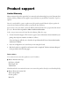
Product support
Chapter
1
Chapter 1:
Introduction
This chapter outlines the key features of the
Matrox Meteor-II /Multi-Channel board.
8 Chapter 1: Introduction
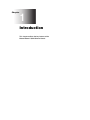
Matrox Meteor-II /Multi-Channel
Matrox Meteor-II /Multi-Channel is a monochrome and component RGB analog
frame grabber for standard and non-standard video acquisition. Matrox Meteor-II
/Multi-Channel is available in a PCI or PC/104-Plus form factor.
VID_IN1_1
VID_IN2_1
2:1
MUX
VID_IN2_2
A/D
Lowpass
filters/
Gain
2:1
MUX
VID_IN3_2
Aux
A/D
8 24
Black
LUT
3 256x8-bit
A/D 8
24
Sync
separator
Optocoupler
Trigger
Clk input
Clk output
Hsync
Vsync
Trigger
Exposure timer1
Exposure timer2
White
Black
4:1
MUX
SYNC_IN
8
Black
White
VID_IN3_1
Either to DB-44
connector
(for PCI
form factor)
or to 30-pin
male
connector
(for
PC/104-Plus
form factor)
White
2:1
MUX
VID_IN1_2
{
TTL
Drivers
&
Receivers
PSG
RS-232
Drivers
and
Receivers
UART
VIA
2
64
Video transfer
memory
(4 Mbytes)
2
RX
TX
/RTS
/CTS
32
Not available on PC/104-Plus
form factor
Host 32-bit PCI bus
Acquisition features
Matrox Meteor-II /Multi-Channel can acquire different types of standard and
non-standard monochrome and component RGB video. The board features six
software-selectable input channels on which two component RGB or six
monochrome cameras can be attached. Matrox Meteor-II /Multi-Channel
Matrox Meteor-II /Multi-Channel
9
supports acquisition from one camera at a time or simultaneous acquisition from
up to three gen-locked RS-170/CCIR cameras. Matrox Meteor-II /Multi-Channel
supports both single and dual-tap configurations. It also accepts an external trigger,
and can operate in either asynchronous reset mode or next valid frame/field mode.
The PCI form factor also includes an auxiliary power supply input, which can be
used to draw auxiliary power from your computer to provide power to your
camera.
Data transfer
The Matrox Meteor-II /Multi-Channel board allows the transfer of live video to
Host memory or off-board display memory. To prevent loss of data during long
bus-access latencies found in heavily loaded computer systems, the Matrox
Meteor-II /Multi-Channel board features 4 Mbytes of video transfer memory for
temporary frame storage. The board is also equipped with the Matrox Video
Interface ASIC (VIA), which acts as a video-to-PCI bridge.
Software
To operate Matrox Meteor-II /Multi-Channel, you can purchase one or more
Matrox Imaging software products that support the Matrox Meteor-II
/Multi-Channel board. These are the Matrox Imaging Library (MIL) and its
derivatives (MIL-Lite, ActiveMIL, ActiveMIL-Lite, and Matrox Inspector). All
Matrox software is supported under Windows; consult your software manual for
supported Windows environments.
❖ Note that, although other software products might be available to operate Matrox
Meteor-II /Multi-Channel, the discussion throughout this manual is based in
terms of Matrox Imaging software products.
MIL
MIL is a development library which provides an extensive list of commands used
to capture, process, analyze, transfer, display, and archive images. Processing and
analysis operations include: geometric transformations, spatial filtering
operations, morphological operations, measurements, blob analysis, optical
character recognition (OCR), pattern recognition (Normalized Grayscale
Correlation pattern matching and Geometric Model Finder), edge extraction
(Edge Finder), matrix/bar code reading, and calibration.
MIL-Lite
MIL-Lite is a subset of MIL. It includes all the MIL commands for image
acquisition, transfer, display control, and archiving.
10 Chapter 1: Introduction
ActiveMIL
ActiveMIL is a set of ActiveX controls that are based on MIL. ActiveMIL was
designed for rapid application development (RAD) tools, such as Microsoft’s
Visual Basic. ActiveMIL is included with MIL (ActiveMIL-Lite is included with
MIL-Lite).
Matrox Inspector
Matrox Inspector is an interactive Windows application for image capture,
processing, analysis, and archiving.
MIL application developers can use Matrox Inspector as a prototyping tool to
quickly build proof-of-concept demonstrations for their machine vision, image
analysis, and medical imaging system. End users can use Matrox Inspector to
perform and automate image enhancement and measurement tasks.
Matrox Intellicam
Matrox Intellicam is an interactive Windows program that allows fast camera
interfacing and provides interactive access to all the acquisition features of your
Matrox board. For boards that accept non-standard video sources, Matrox
Intellicam also has the ability to create custom digitizer configuration format
(DCF) files, which MIL and its derivatives use to interface to specific non-standard
video sources. Matrox Intellicam is included with MIL /ActiveMIL and MIL-Lite
/ActiveMIL-Lite.
For more information about Matrox Intellicam, refer to the Matrox Intellicam User
Guide.
What you need to get started
To begin using Matrox Meteor-II /Multi-Channel, you need the following:
• A computer with a PCI bus and an Intel Pentium processor (or equivalent) or
better.
• Microsoft Windows if using Matrox Imaging software (consult the Matrox
Imaging software package for specific supported environments and computer
memory/storage requirements).
Other useful
considerations
• A computer with a newer PCI chipset, such as the Intel 440BX, 810, 815E, 820,
840, 845PE, 850, 860, E7500, or E7505 for full Matrox Meteor-II functionality.
These chipsets are recommended because they generally offer better performance
in terms of data transfer rates.
Inspecting the Matrox Meteor-II /Multi-Channel package
11
• A computer with an empty 32-bit PCI expansion slot (bus-master capable).
• A CD drive, and a hard disk or network drive on which to install the Matrox
Meteor-II software.
Inspecting the Matrox Meteor-II
/Multi-Channel package
When you unpack your Matrox Meteor-II /Multi-Channel package, you should
check its contents. Note that optional parts might or might not be included,
depending on what you ordered. If something is missing or damaged, contact your
Matrox representative.
Standard package
If you ordered Matrox Meteor-II /Multi-Channel, you should receive the
following items:
• The Matrox Meteor-II /Multi-Channel board.
• The Matrox Meteor-II /Multi Channel Installation and Hardware Reference manual
(this document).
• A 4-pin power cable, included with Matrox Meteor-II /Multi-Channel for PCI
form factor.
• A 30-pin connector to interface with the video input connector, included with
Matrox Meteor-II /Multi-Channel for PC/104-Plus (stand-alone version).
Optional items
You might have also ordered one or more of the following:
• MIL-32/CD, which includes ActiveMIL; MIL-LITE/CD, which includes
ActiveMIL-Lite; or Matrox INSPECTOR-32/CD. Both the MIL and MIL-Lite
CDs include Matrox Intellicam.
• DBHD44-TO-8BNC input cable with a high density 44-pin connector and eight
BNC connectors for Matrox Meteor-II /Multi-Channel for PCI. Three
BNC-TO-SVHS (Y/C) adapter cables are shipped with the DBHD44-TO-8BNC
cable.
12 Chapter 1: Introduction
• DH44-TO-8BNC/O input cable with a high density 44-pin connector. This cable
is required if you want to connect to special input and output signals, such as
synchronization signals, control signals, and DC power output.
Handling components
The electronic circuits in your computer and the circuits on Matrox Meteor-II
/Multi-Channel are sensitive to static electricity and surges. Improper handling
can seriously damage the circuits. Be sure to follow these precautions:
• Drain static electricity from your body by touching a metal fixture (or ground)
before you touch any electronic component.
• Avoid letting your clothing come in contact with the circuit boards or
components.
Caution
Before you add or remove devices from your computer, always turn off the power
to your computer and all peripherals.
Installation overview
The installation procedure consists of the following steps:
1. Complete the hardware installation as described in Chapter 2. If you have any
problems, refer to Appendix A.
2. Complete the software installation as described in the documentation
accompanying your software package.
More information
For information on using multiple Matrox Meteor-II boards, refer to Chapter 3,
and for in-depth hardware information, refer to Chapter 4.
If you want technical information about Matrox Meteor-II /Multi-Channel,
including specifications and connector descriptions, and pinouts, refer to
Appendix B.
A revision history for the development of Matrox Meteor-II /Multi-Channel is
available in Appendix C.
Installation overview
Conventions
13
When the term Host is used in this manual, it refers to your computer.
This manual occasionally makes reference to a MIL-Lite command. However,
anything that can be accomplished with MIL-Lite can also be accomplished with
MIL, ActiveMIL, ActiveMIL-Lite, or Matrox Inspector.1
Need help?
Appendix A offers solutions to potential problems. If your Matrox Meteor-II
/Multi-Channel installation questions are not answered in this manual, contact
your local Matrox representative, Matrox Sales Office, or Matrox Imaging
Customer Support Group (see the Customer Support section at the back of this
manual for telephone numbers).
In the unlikely event of a failure, the warranty and Product Assistance Request Form
at the back of this manual outlines return conditions and procedures.
1. Most items can be accomplished with Matrox Inspector.
14 Chapter 1: Introduction
Chapter
2
Chapter 2:
Hardware
installation
This chapter explains how to install the
Matrox Meteor-II /Multi-Channel hardware.
16 Chapter 2: Hardware installation
Installing Matrox Meteor-II /Multi-Channel
Before you install your board, some precautionary measures must be taken. Turn
off the power to the computer and its peripherals, and drain static electricity from
your body (by touching a metal part of the computer chassis). Next, follow the
steps to install your board according to its form factor: PCI or PC/104-Plus.
❖ If you are not using Windows NT as your operating system, your board must be
installed before you install the software (either MIL or one of its derivatives). If
you are adding another Matrox Meteor-II to your computer, you will have to
re-install your software after installing your board.
Installing Matrox Meteor-II /Multi-Channel for PCI
Use the following steps to install your Matrox Meteor-II board for PCI:
1. Remove the cover from your computer using the instructions from your computer
manual.
2. Check that you have an empty PCI (32-bit) slot that can accommodate the board.
If you do not have an empty slot, remove a PCI board from your computer to
make room for your Matrox Meteor-II board and take note of the slot number
you choose.
Connectors of an AGP slot
Connectors of PCI slots
or
Connectors of ISA slots
Installing Matrox Meteor-II /Multi-Channel
Caution
17
Some computers have a large, black-ridged heat sink that prevents boards from
occupying most PCI slots. Your Matrox Meteor-II must not touch this heat sink.
Therefore, choose a slot where the board completely avoids it.
3. If present, remove the blank metal plate located at the back of the selected slot.
Keep the removed screw; you will need it to fasten the Matrox Meteor-II board.
4. Carefully position Matrox Meteor-II in the selected PCI slot as illustrated below.
If you are using a tower computer, orient the board to suit the board slots in your
computer.
SCREW
METAL
PLATE
MATROX M
ETEOR-II
PCI form factor
32-BIT PCI BOARD SLOT
5. Once perfectly aligned with an empty slot, press the board firmly but carefully
into the connector.
6. Anchor the board by replacing the screw that you removed.
7. Connect your video sources. For details, see the Connecting external devices section.
8. Turn on your computer.
18 Chapter 2: Hardware installation
In some cases, when you boot your computer, Windows’ Plug-and-Play system
will detect a new PCI card and you will be asked to assign a driver to it. At this
point, you should click on Cancel because the driver will be installed during the
installation of MIL or one of its derivatives.
Installing Matrox Meteor-II /Multi-Channel for PC/104-Plus
This section refers to the stand-alone version of Matrox Meteor-II /Multi-Channel
for PC/104-Plus. The version pre-configured for Matrox 4Sight-II is not discussed
in this manual. For more information, see Note about Matrox Meteor-II
/Multi-Channel for PC/104-Plus later in this chapter.
Use the following steps to install your Matrox Meteor-II board for PC/104-Plus:
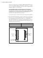
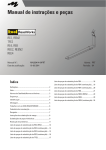
1. Matrox Meteor-II for PC/104-Plus can operate in either a 5V or 3.3V system. In
some cases, a hole in the PC/104-Plus (PCI) connector is filled, which prevents
another PC/104-Plus board from being stacked on top. To install Matrox
Meteor-II for PC/104-Plus in a system with a specific signalling environment, a
pin must be removed. The table and diagram below indicate which pins to cut,
and their locations on the connector.
Signalling environment
Pin to remove on J3 connector
5V
A1
3.3V
D30
Remove pin D30
in a 3.3 V system
J1
J3
30
32
J2
19
PC/104-Plus
ISA
connectors
PC/104-Plus
PCI
connector
0
CD
1
PC/104-Plus
expansion site
DCBA
Remove pin A1
in a 5 V system
1
BA
Top view
Installing Matrox Meteor-II /Multi-Channel
19
2. Check that you have an available PC/104-Plus connector on the motherboard, or
verify that your existing stack can support another board.
3. Remove the anchoring screws from the stack; do not discard them since you will
need them to fasten the Matrox Meteor-II board.
4. If you have existing PC/104 boards in your computer, remove them and stack
them on the PC/104-Plus board. PC/104 boards must be stacked last.
5. Carefully position Matrox Meteor-II over the connectors and press the board
firmly into place.
6. Replace the anchoring screws.
7. Set the rotary switch (next to the PC/104 (ISA) P2 connector) to 0 if installing
the first stackable board, or another appropriate setting if not the first. See the
section, Multiple board installation, in Chapter 3.
P1
P2
PC/104-Plus
(PCI) connector
PC/104
(ISA)
P1 and P2
connectors
Rotary
switch
Motherboard
Video input
connector
8. Connect your video sources. For details, see the Connecting external devices section.
9. Turn on your computer.
20 Chapter 2: Hardware installation
In some cases, when you boot your computer, Windows’ Plug-and-Play system
will detect a new PCI card and you will be asked to assign a driver to it. At this
point, you should click on Cancel because the driver will be installed during the
installation of MIL or one of its derivatives.
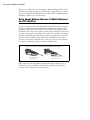
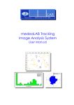
Note about Matrox Meteor-II /Multi-Channel
for PC/104-Plus
A version of the Matrox Meteor-II /Multi-Channel for PC/104-Plus accompanies
the Matrox 4Sight-II integrated unit. It differs slightly in its structure from its
stand-alone counterpart. The stand-alone version of the Matrox Meteor-II for
PC/104-Plus has a video input connector that lies in the same plane as the board
(in other words, the pins are parallel to the board). The version that accompanies
the Matrox 4Sight-II integrated unit lies in a plane perpendicular to the board.
The latter allows the Matrox Meteor-II board to be hardwired to the input
connector of the Matrox 4Sight-II unit; as such, it can only be used as the first
board in the PC/104-Plus stack on the Matrox 4Sight-II unit.
Matrox Meteor-II for PC/104-Plus frame grabber (inverted view)
Video Input connector
pins for Matrox Meteor-II
For Matrox 4Sight
Video Input connector
pins for Matrox Meteor-II
Stand-alone version
When ordered as part of the Matrox 4Sight-II unit, Matrox Meteor-II for
PC/104-Plus comes pre-installed. See the Matrox 4Sight-II installation and
hardware reference manual for more information.
Connecting external devices
21
Connecting external devices
This section will discuss the connectors for the Matrox Meteor-II /Multi-Channel
PCI and PC/104-Plus form factors.
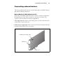
Matrox Meteor-II /Multi-Channel for PCI
Matrox Meteor-II /Multi-Channel has three connectors, which are indicated in
the diagram below. One of these connectors is located on its bracket. The
connectors listed are discussed in detail in Appendix B.
• Video input connector. Used to receive analog video, as well as send and receive
synchronization signals and power.
• Auxiliary power supply input. Used to route power from your computer through
the Matrox Meteor-II board to your camera.
Auxiliary power supply input
Video input
PCI connector
22 Chapter 2: Hardware installation
Connecting a video input to Meteor-II /Multi-Channel for PCI
Connect video sources to Matrox Meteor-II /Multi-Channel’s video input
connector, using the optional DBHD44-TO-8BNC cable. This cable has eight
BNC connectors and a 44-pin high-density D-Subminiature plug. The wires of
the cable are color-coded as follows:
Wires
Signals
Description
RED (1)
VID1_IN1
Analog Video Input1, R
GREEN (2)
VID1_IN2
Analog Video Input2, G
BLUE (3)
VID1_IN3
Analog Video Input3, B
BLACK (4)
SYNC_IN
SYNC input
GREY (5)
OPTOTRIG+*
External trigger input
WHITE (6)
VID2_IN1
Analog Video Input4, R
YELLOW (7)
VID2_IN2
Analog Video Input5, G
PURPLE (8)
VID2_IN3
Analog Video input6, B
*OPTOTRIG- is usually connected to the ground of the trigger source. It is the shield of the gray BNC.
Connecting Matrox Meteor-II /Multi-Channel for PCI to the auxiliary power
supply input
To use Matrox Meteor-II /Multi-Channel to power your camera:
1. Use the 4-pin power cable to connect the auxiliary power supply connector to the
power supply in the computer.
2. Ensure that the jumper is across the appropriate Matrox Meteor-II auxiliary power
supply selection pins, for the required voltage (5 V or 12 V). See Appendix B for
a diagram.
3. Use the DBHD44-TO-8BNC/O cable to connect your camera’s video output and
power supply input to the video input connector. Note that the total current drawn
by all the cameras is limited to 1.5 A, and the circuit uses an auto-resettable fuse.
Connecting external devices
23
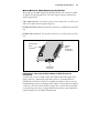
Matrox Meteor-II /Multi-Channel for PC/104-Plus
Matrox Meteor-II /Multi-Channel for PC/104-Plus has four connectors, which
are indicated in the diagram below. The video input connector is discussed in
detail in Appendix B.
• Video input connector. A connector used to receive analog video, as well as send
and receive synchronization signals and power.
• PC/104-Plus (PCI) connector. An interface connector to send data across the PCI
bus.
• PC/104 (ISA) connectors. Two interface connectors to send data across the ISA
bus.
PC/104-Plus
(PCI)
connector
PC/104
(ISA)
P1 and P2
connectors
P2
P1
Video input
connector
Connecting a video input to Matrox Meteor-II /Multi-Channel for
PC/104-Plus
Connect video sources to Matrox Meteor-II /Multi-Channel through its video
input connector, a 30-pin right-angle male connector. A standard cable for
PC/104-Plus form factor boards is not available from Matrox. You can use the
included mating connector, crimp the ribbon cable to it and attach your required
connector to the other end of the ribbon cable. Then, connect this custom cable
to the video input connector. See Appendix B for the pinouts, signals, and ribbon
cable information for the /Multi-Channel board.
24 Chapter 2: Hardware installation
The Matrox Meteor-II /Multi-Channel for PC/104-Plus, designed for Matrox
4Sight-II, has a custom video input connector that attaches directly to the
motherboard, which in turn, is hard-wired to the video-input connector on the
back side of the unit. Therefore, you can interface a camera with the PC/104-Plus
board by connecting the camera to your unit’s video input connector. Detailed
information on connecting a video input to this board can be found in the Matrox
4Sight-II installation and hardware reference manual.
Chapter
3
Chapter 3:
Using multiple
Matrox Meteor-II
boards
This chapter explains how to use multiple Matrox Meteor-II
boards.
26 Chapter 3: Using multiple Matrox Meteor-II boards
Multiple board installation
This section describes how to use multiple Matrox Meteor-II boards.
Installing multiple
PCI boards
Install each additional Matrox Meteor-II board for PCI as you installed the first
board (refer to Chapter 2). In other words, place each additional board in an empty
slot. For the PCI form factor, ensure that the installed boards avoid the CPU heat
sink.
Theoretically, you can have as many as 16 Matrox Meteor-II PCI boards installed
in your computer at one time; this number is, however, limited by the number of
empty slots in your computer and, for simultaneous grabs, by the available
bandwidth of your computer (discussed later in this chapter).
Using MIL-Lite, you have to allocate a MIL system for each board and allocate
the resources of each MIL system.
Installing multiple
PC/104-Plus boards
The number of PC/104-Plus boards that you can stack depends on the computer
you are using. If using a Matrox 4Sight-II integrated unit, you can stack a
maximum of three PC/104-Plus boards, as shown in the following diagram. Note
that if you have PC/104 boards in your computer, they must be placed at the top
of the stack.
Top screw
ISA connectors
PCI connector
Host board
Grabbing simultaneously from different boards
27
In addition, you should set the rotary switch of each PC/104-Plus board to a
unique setting in the stack. Setting the rotary switch dedicates a group of PCI
signals to the board in the stack: clock, request grant, ID select, and interrupt
signals. It is recommended that the first board installed (the board closest to the
Host CPU board) be configured to 0, the second 1, and so on. The table below
shows the recommended switch setting for each board, as well as the corresponding
setting for the dedicated signals.
Switch position
Board position
Interrupt
Request grant
ID select
0 or 4
1
Interrupt A
0
0
1 or 5
2
Interrupt B
1
1
2 or 6
3
Interrupt C
2
2
3 or 7
4
Interrupt D
2
3
If you are installing an additional Matrox Meteor-II board on a Matrox 4Sight-II
unit, the board already installed has the setting fixed at 0; therefore, the setting
for the additional board must be something other than 0 or 4.
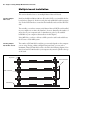
Grabbing simultaneously from different
boards
You can simultaneously grab images from cameras attached to different
Matrox Meteor-II boards; however, the number of cameras from which you can
simultaneously grab is determined by the PCI bandwidth available in your
computer.
PCI bandwidth
requirements
Matrox Meteor-II /Multi-Channel has a low susceptibility to PCI bus latency due
to its 4 Mbytes of video transfer memory. In addition, sustained PCI-transfers to
memory require the use of a high performance PCI core-logic chipset, such as the
Intel 820, 840, 850, 860, or E7505. If a high performance chipset is used with a
Matrox Meteor-II /Multi-Channel board, you should not have any PCI
28 Chapter 3: Using multiple Matrox Meteor-II boards
bandwidth problems when grabbing up to two full-sized color images
simultaneously (using two boards). However, grabbing more than two full-sized
color images simultaneously might result in PCI bandwidth problems.
Matrox Meteor-II
Camera 1
Matrox Meteor-II
Camera 2
Grabbing from two Matrox Meteor-II boards
.
As a reference point, grabbing one 640 x 480 image in real time will require a PCI
bandwidth of 35 Mbytes/sec when transferring in RGBX (32-bit) mode.
When grabbing from three or more Matrox Meteor-II boards simultaneously, you
will have to reduce the image size to avoid reaching the upper limits of the overall
available bandwidth.
Chapter
4
Chapter 4:
Hardware reference
This chapter explains the architecture of the
Matrox Meteor-II /Multi-Channel hardware, as well as the
available features and modes.
30 Chapter 4: Hardware reference
Matrox Meteor-II hardware reference
This chapter provides information on the architecture, operating modes, and
supported features of the Matrox Meteor-II /Multi-Channel board.
For a summary of the information given in this chapter and detailed specifications
of connectors and pinouts, refer to Appendix B of this manual.
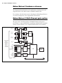
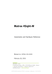
Matrox Meteor-II /Multi-Channel grab section
The grab section of the Matrox Meteor-II /Multi-Channel board captures
monochrome or component RGB video signals from standard and non-standard
cameras. Six monochrome or two component RGB cameras can be attached.
VID_IN1_1
VID_IN2_1
2:1
MUX
VID_IN2_2
A/D
Lowpass
filters/
Gain
2:1
MUX
VID_IN3_2
Aux
A/D
8 24
Black
LUT
3 256x8-bit
A/D 8
24
Sync
separator
Optocoupler
Trigger
Clk input
Clk output
Hsync
Vsync
Trigger
Exposure timer1
Exposure timer2
White
Black
4:1
MUX
SYNC_IN
8
Black
White
VID_IN3_1
Either to DB-44
connector
(for PCI
form factor)
or to 30-pin
male
connector
(for
PC/104-Plus
form factor)
White
2:1
MUX
VID_IN1_2
{
TTL
Drivers
&
Receivers
PSG
RS-232
Drivers
and
Receivers
UART
VIA
2
64
Video transfer
memory
(4 Mbytes)
2
RX
TX
/RTS
/CTS
32
Not available on PC/104-Plus
form factor
Host 32-bit PCI bus
Matrox Meteor-II /Multi-Channel grab section
Performance
31
The video timing parameters (including those for progressive scan) supported by
the Matrox Meteor-II /Multi-Channel board are as follows:
Max
Number of pixels / line (including sync and blanking)
4096*
Number of lines / frame (including sync and blanking)
4096*
Sampling rate (with external clock input, or in line-locking mode)
30 MSPS
Note that the maximum number of pixels per line that MIL supports is:
Pixels
-------------- x Number of Lines ≤ 4 Mbytes
Line
Input channels
The Matrox Meteor-II /Multi-Channel has six independent analog channels.
These channels can support switching between input from two RGB or six
monochrome cameras where the channels can be selected with the MIL-Lite
MdigChannel() command.
Low-pass filter
The input low-pass filtering stage is used to limit high frequency noise and aliasing
effects at the input of the A/D converters. The filters used on
Matrox Meteor-II /Multi-Channel are 4th order Butterworth filters with a cutoff
frequency of 10 MHz.
Gain
Matrox Meteor-II /Multi-Channel has adjustable gains. This allows you to
optimize the video input signal range.
You can change the gain value using the MIL-Lite MdigControl() command. The
supported gain factors are as follows:
Input video signal amplitude
(excluding sync)
Total input video signal amplitude
(including sync)
Required gain
setting
MIL
0.0 V up to 0.5 V
0.0 - 0.7 Vpp
4
M_GAIN3
0.5 V up to 0.7 V
0.7 - 1.0 Vpp
2.8 (default)
M_GAIN2
0.7 V up to 1.0 V
1.0 - 1.4 Vpp
2
M_GAIN1
32 Chapter 4: Hardware reference
Input video signal amplitude
(excluding sync)
Total input video signal amplitude
(including sync)
Required gain
setting
MIL
1.0 V up to 1.5 V
1.4 - 2.1 Vpp
1.3
M_GAIN0
1.5 V up to 2.0 V
2.1 - 2.9 Vpp
1
M_GAIN4
Discrete A/D converters
Three discrete A/D converters with external reference generation and sync slicing
are used for component RGB digitization. The converters can be operated at up
to 30 MSPS.
In addition, the converters black and white reference levels can be adjusted
individually. The black and white reference levels can be adjusted between 0.6 V
to 1.6 V and 1.6 V to 2.6 V respectively, in increments of 10.23 mV (98 distinct
adjustments).
Use the MIL-Lite MdigReference() command to set the black and white reference
levels.
PSG
The Programmable Synchronization Generator (PSG) is responsible for managing
all timing and synchronization signals.
Phase-locked loop
The high-performance, low-jitter phase-locked loop (PLL) uses frequency
synthesis techniques to generate the clock signal, when necessary.
The PLL can use the following sources as a reference:
• The on-board crystal oscillator.
• The horizontal video synchronization signal supplied by the video source
(line-locked mode).
• The clock signal supplied by the video source (to generate a different clock).
When in line-locked mode and accepting a composite video signal, the PLL can
synchronize to either serrated or block vertical synchronization signals.
When the input source supplies a sampling clock that does not require adjustment,
the PLL is bypassed to avoid adding jitter to the supplied clock.
Matrox Meteor-II /Multi-Channel grab section
33
Synchronization
Matrox Meteor-II /Multi-Channel can operate in either slave or master mode.
Slave mode
• In slave mode, the video source provides the synchronization information to
Matrox Meteor-II /Multi-Channel. It can accept one of the following
synchronization schemes:
- The video source encodes the synchronization signals on the analog video signal
provided to the board.
- The video source supplies the horizontal and/or vertical synchronization signals
separately in TTL format.
- The video source provides a composite synchronization signal in TTL format,
separate from the analog video.
• Synchronization information can be sent either with the video data, or on a
separate analog synchronization channel.
Master mode
• In master mode, Matrox Meteor-II /Multi-Channel generates (using the PSG)
the horizontal and/or vertical (TTL) synchronization signals and supplies them
to the video source. This allows the video source to synchronize to the board.
Trigger
Matrox Meteor-II /Multi-Channel accepts an external trigger input which allows
image acquisition to be synchronized to external events. The board can operate
in one of two modes, and the selected mode is specified by the DCF.
Matrox Meteor-II /Multi-Channel can operate in next valid frame/field mode
When in this mode, the digitizer waits for the next valid frame or field (as specified
by the DCF file) before commencing the grab. This trigger mode functions in one
of three ways:
• Edge-triggered monoshot acquisition: The VIA (Video Interface Asic) waits for
the rising/falling edge to capture a single frame.
• Edge-triggered continuous acquisition: The VIA waits for the rising/falling edge
to start a continous grab.
• Level-sensitive "continuous" acquisition: The VIA grabs continuously while the
level of the trigger is high/low.
34 Chapter 4: Hardware reference
❖ The polarity of the active and inactive levels of the trigger signal is software
programmable.
Matrox Meteor-II /Multi-Channel can also operate in asynchronous reset mode.
In this mode, the digitizer resets the camera to begin a new frame when the trigger
signal is received.
Direct TTL trigger
Trigger signals can be received in TTL format directly through the video-input
connector. The TTL level signal must have a maximum amplitude of 5 V. A signal
over 2 V is considered high while anything less than 0.8 V is considered low. The
transition of 0.8 V to 2 V is considered to be the rising edge.
The trigger signal’s pulse width must be greater than one pixel. You can determine
the pulse width by taking the inverse of the pixel frequency. For example, if the
pixel frequency is 12.27 MHz, the minimum pulse width is 1/12.27 MHz ≈ 82
nanoseconds.
Opto-isolated trigger
Trigger signals connected to the OPTOTRIG- and OPTOTRIG+ input pins, pass
through an opto-coupler, a device that protects the board from outside surges;
OPTOTRIG- is usually connected to the ground of the trigger source. The voltage
difference across OPTOTRIG+ and OPTOTRIG- must be between 4.05 V and
9.16 V for logic high, and between -5.0 V and 0.8 V for logic low. Refer to
Appendix B for the pinouts of these signals on your board.
UART
Matrox Meteor-II /Multi-Channel features a Universal Asynchronous
Receiver/Transmitter (UART) that provides an RS-232 serial interface. For
example, this allows you to remotely control a camera or a motion control unit,
or communicate with a program logic controller (PLC). The UART is
programmed using the MIL-Lite command MdigControl() with the M_UART...
control types.
Note that the UART is not present on the Meteor-II /Multi-Channel for
PC/104-Plus.
Data interfaces
35
Lookup tables
Matrox Meteor-II /Multi-Channel has three 256x8-bit input lookup tables
(LUTs), allowing independent re-mapping of three 8-bit input streams.
The LUTs on the Matrox Meteor-II /Multi-Channel for PCI support RGB 8:8:8
(24-bit) output pixel formats. The LUTs on the PC/104-Plus form factor support
RGB 8:8:8, RGB 5:6:5, and RGB 5:5:5 output pixel formats. LUTs are
programmed using the MIL-Lite command, MdigLut().
User bits
Matrox Meteor-II /Multi-Channel supports four auxiliary TTL user bits through
the video input connector: two inputs and two outputs. These are available for
controlling external events such as a strobe light or PLC. User bits are programmed
using the MIL-Lite command MdigControl().
Using the auxiliary power supply
Matrox Meteor-II /Multi-Channel can supply power to your camera. Use the
4-pin power cable provided with your board to connect to the power supply of
your computer. The operating voltage can be set to either 5 V or 12 V, but the
current drawn by all cameras is limited to 1.5 A. The circuit uses an auto-resettable
fuse. For further information on connecting to the auxiliary power supply
connector, see the section, Connecting Matrox Meteor-II /Multi-Channel for PCI
to the auxiliary power supply input in Chapter 2, and Appendix B. Note that this
input is not available on the PC/104-Plus form factors.
Data interfaces
Video Interface ASIC
The Matrox Meteor-II /Multi-Channel board has a VIA, which acts mainly as a
video-to-PCI bridge. The VIA is capable of high-speed image transfers to Host
memory or other PCI devices across the PCI bus. It uses 4 Mbytes of video transfer
memory to store data until the PCI bus becomes available.
Simultaneous data
streams
Matrox VIA can manage up to two simultaneous data streams. For example, it
can grab into video transfer memory, and concurrently transfer data over the PCI
bus.
General features
The VIA is capable of separating image data into two or three, 8-bit components
(for example, RGB packed to RGB planar). This mechanism is also used to merge
line segments of monochrome multi-tap cameras.
36 Chapter 4: Hardware reference
PCI interface
Matrox Meteor-II has a 32-bit PCI bus interface, capable of a peak transfer rate
of 132 Mbytes/sec.
The VIA’s PCI
interface
The VIA's PCI interface is 32 bits wide and operates at 33 MHz. It allows all VIA
resources to be accessed through a 128-Mbyte memory region, mappable
anywhere in the 4-Gbyte PCI address space.
Read pre-fetch and write posting buffers are integrated to optimize Host access.
Appendix A:
Troubleshooting
This appendix gives suggestions to help you resolve
potential problems. If your problem is not addressed here,
contact your local Matrox representative, Matrox Sales
Office, or the Matrox Imaging Customer Support Group.
38 Appendix A: Troubleshooting
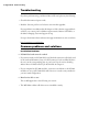
Troubleshooting
If you have problems using your Matrox Meteor-II board, please try the following:
• Check for disconnected power cords.
• Read the Common problems and solutions section in this appendix.
If your problem is not addressed in this chapter or if the solutions suggested don’t
work for you, contact your local Matrox representative, Matrox Sales Office, or
the Matrox Imaging Customer Support Group.
For up-to-the minute release and customer support information, visit our website:
http://www.matrox.com/imaging
Common problems and solutions
Installation Problems
➘ PC/104-Plus board cannot be stacked
• If you cannot stack your PC/104-Plus board, check the connectors of the last board
in the stack and determine if any of its PCI connector’s holes are filled. If this is
the case, cut the corresponding pins on your board. See the section Installing
Matrox Meteor-II /Multi-Channel for PC/104-Plus in Chapter 2.
• If your computer has PC/104 modules, you must re-stack them so the PC/104
modules are on top of PC/104-Plus boards. Be sure to reset the rotary switches for
your new stack configuration.
➘ Board service fails to start
This could happen due to the following two reasons:
• The MIL Matrox Meteor-II drivers are not installed correctly.
Common problems and solutions
39
- When the board fails to start under Windows 2000, the driver might not have
started. Right-click on My Computer, and select Manage from the presented
menu. From the Computer Management explorer window, select System
Tools, followed by Device Manager. If you do not see a Meteor-II device under
Matrox Imaging Adapters, you will have to reinstall the driver.
- When the board fails to start under Windows XP, the driver might not have
started. Click on the Start button, open the Control Panel, select
Administrative Tools, and open Computer Management. From the Computer
Management explorer window, select System Tools, followed by Device
Manager. If you do not see a Meteor-II device under Matrox Imaging Adapters,
you will have to reinstall the driver.
If the above solution for your operating system does not work, try the following.
- The driver also might not start due to too much or insufficient allocation of
DMA memory. To address this problem, re-allocate DMA memory using the
included milconfig.exe utility.
• There is a conflict in the BIOS Setup program. This problem generally occurs
when there is a PCI memory mapping error or when there is a PCI-IRQ routing
error. To resolve this problem with the PCI form factor, first try to swap boards
from one PCI slot to another; for the PC/104-Plus, change the rotary switch
settings. If the problem still persists, try upgrading your BIOS.
If the above solution does not work, try the following to determine if there is an
IRQ conflict.
- Under Windows 2000, right-click on My Computer, and select Manage from
the presented menu. From the Computer Management explorer window,
display the System Tools\ System Information\ Hardware Resources\ IRQs folder.
Check for devices that are sharing an IRQ with your Matrox frame grabber.
- Under Windows XP, click on the Start button, open the Control Panel, select
Administrative Tools, and open Computer Management. From the Computer
Management explorer window, select System Tools, followed by Device
Manager. From the View menu, select the Resources by type, and expand the
Interrupt request (IRQ) folder. Check for devices that are sharing an IRQ with
your Matrox frame grabber.
40 Appendix A: Troubleshooting
➘ Not enough memory to allocate grab buffer
This is the message that you will receive if you try to allocate a grab buffer that is
greater than the amount of DMA memory specified during software installation.
This problem can be addressed by changing the amount of DMA memory on
your computer. Re-allocate DMA memory using the included milconfig.exe utility.
Alternatively, uninstall and reinstall MIL and specify the appropriate amount of
DMA memory.
Grabbing Problems
➘ The trigger pulse is not being sent
This happens when the opto-isolated trigger pulse is not connected. When using
the opto-isolated trigger, both OPTOTRIG- and OPTOTRIG+ signals must be
connected. OPTOTRIG- is usually connected to the ground of the trigger source.
➘ IRQ conflicts
In general, PCI devices can share an interrupt line (IRQ). However, sometimes
this might not be possible. The types of difficulties that you might run into are as
follows:
• IRQ conflict under Windows 2000/XP
- To resolve this problem with the PCI form factor, re-assign a different IRQ line
to the PCI slot in which the Matrox Meteor-II board is installed.
- To resolve this problem with the PC/104-Plus form factor, change the rotary
switch settings.
❖ Note that PCI devices cannot share interrupt lines with EISA or ISA devices.
Other possible solutions to the above problems:
- Move the Matrox Meteor-II board to another (free) PCI slot.
- Swap Matrox Meteor-II with another board, by switching PCI slots.
Contacting Matrox
41
Problems during application development
➘ Computer 'hangs' or produces unwanted results while an application is running
Sometimes, an EISA or ISA device might attempt to use the same interrupt,
registers, or memory space as PCI boards, and this causes a conflict. Check for an
interrupt, memory, or register conflict:
• Under Windows 2000, right-click on My Computer, and select Manage from the
presented menu. From the Computer Management explorer window, select
System Tools\ System Information\ Hardware Resources\ IRQs folder. Check for
devices that are sharing an IRQ with your Matrox frame grabber.
• Under Windows XP, click on the Start button, open the Control Panel, select
Administrative Tools, and open Computer Management. From the Computer
Management explorer window, select System Tools, followed by Device Manager.
From the View menu, select the Resources by type, and expand the Interrupt
request (IRQ) folder. Check for devices that are sharing an IRQ with your Matrox
frame grabber.
Contacting Matrox
Before contacting your local Matrox representative, Matrox Sales Office, or the
Matrox Imaging Customer Support Group, you will need the following
information:
• A description of what happened.
• Computer (motherboard) make and model number, environment, and
peripherals (especially boards sharing the computer with your Matrox Meteor-II).
• Your board’s serial number (printed on the bar code label), and revision number.
Use the Product Assistance Request Form at the back of this manual to record the
necessary information.
42 Appendix A: Troubleshooting
Appendix B:
Technical
information
This appendix contains information that might be useful
when installing your Matrox Meteor-II /Multi-Channel board.
44 Appendix B: Technical information
Technical information
This appendix contains information that might be useful when installing your
Matrox Meteor-II /Multi-Channel board.
Global information
• Operating system. See your software manual for supported versions of Microsoft
Windows.
• System requirements. A computer with a PCI bus and an Intel Pentium processor
(or equivalent) or better.
Some older systems use a core logic chipset (interfaces PCI with Host memory)
that has limited throughput capabilities. Matrox Meteor-II might not be able to
attain full functionality on such systems. We recommend systems with newer PCI
chipsets, such as the Intel 440BX, 810, 815E, 820, 840, 845PE, 850, 860, E7500,
or E7505. If you need more specific information regarding potential problems,
refer to Appendix A - Troubleshooting.
Technical features
• Six software selectable channels, which support switching between six
monochrome or two component RGB video inputs. Any of these channels can
serve as the sync channel; however, there is also a separate sync channel.
• Support for both single and dual-tap (channel) monochrome cameras.
• Support for an external trigger input in either next valid frame/field mode or
asynchronous reset mode.
• Three 256 8-bit input lookup tables. The LUTs on the
Matrox Meteor-II /Multi-Channel for PCI support RGB 8:8:8 (24-bit) output
pixel formats. The LUTs on the PC/104-Plus form factor support RGB 8:8:8,
RGB 5:6:5, and RGB 5:5:5 output pixel formats.
• 4 Mbytes of video transfer memory.
• Programmable reference levels.
• Various input gain settings.
Board input and output connectors
45
• RS-232 port (UART) on Matrox Meteor-II /Multi-Channel for PCI.
• Strap-selectable 5 or 12 V DC output (PCI form factor only).
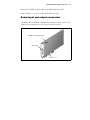
Board input and output connectors
The Matrox Meteor-II /Multi-Channel PCI form factor has three connectors: an
auxiliary power supply input, a video input, and a PCI connector.
Auxiliary power supply input
Video input
PCI connector
46 Appendix B: Technical information
PC/104-Plus form
factor
Matrox Meteor-II for the PC/104-Plus form factor (stand alone version) has four
interface connectors: video input, a PC/104-Plus (PCI) connector, and two
PC/104 (ISA) connectors.
PC/104-Plus
(PCI)
connector
PC/104
(ISA)
P1 and P2
connectors
P2
P1
Video input
connector
Note that the video input connector for the PC/104-Plus board built for
Matrox 4Sight-II is right-angled, unlike the one for the stand-alone version,
discussed here. See Note about Matrox Meteor-II /Multi-Channel for PC/104-Plus in
Chapter 2 for more details.
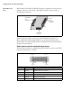
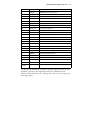
Video input connector on the PCI form factor
The video input connector is a high density DB-44 female connector on the PCI
form factor. Its pinout is as follows:
pin 15
pin 1
pin 44
pin 31
pin 30
pin 16
Pin
Signal
Description
15
VID1_IN1
RED Analog Video Input (Channel 1).
44
VID1_IN2
GREEN Analog Video Input (Channel 1).
13
VID1_IN3
BLUE Analog Video Input (Channel 1).
43
SYNC_IN
Analog Video Input (SYNC).
11
VID2_IN1
RED Analog Video Input (Channel 2).
Board input and output connectors
Pin
Signal
Description
41
VID2_IN2
GREEN Analog Video Input (Channel 2).
40
VID2_IN3
BLUE Analog Video Input (Channel 2).
35
OPTOTRIG+
Opto-Isolated trigger positive input.
34
OPTOTRIG-
Opto-Isolated trigger negative input.
20
TRIGGER
Non-Protected TTL trigger input.
19
CLK_IN_TTL
Clock input (TTL).
33
CLK_OUT_TTL
Clock output (TTL).
32
VSYNC_TTL
Vsync input or output (TTL).
2
HSYNC_TTL
Hsync input or output (TTL).
38
EXP(1)
Exposure #1 output (TTL).
23
EXP(2)
Exposure #2 output (TTL).
36
TX
Transmit (RS-232).
22
RX
Receive (RS-232).
6
CTS
CTS (RS-232).
21
RTS
RTS (RS-232).
39
USER1IN+
Auxiliary User Input #1 (positive).
12
USER1IN-
Auxiliary User Input #1 (negative).
9
USER2IN+
Auxiliary User Input #2 (positive).
10
USER2IN-
Auxiliary User Input #2 (negative).
24
USER1OUT
Auxiliary User Output #1 (TTL).
8
USER2OUT
Auxiliary User Output #2 (TTL).
1, 16
DC POWER
+12 V OR +5 V Power Supply.
7, 37
NC
Not connected.
3-5, 14, 17-18,
25-31,42
GND
Ground.
47
Use Matrox cable DBHD44-TO-8BNC to interface with this connector. It has
eight BNC connectors and a high-density 44-pin D-Subminiature male
connector. This cable allows you to attach up to six video sources, an analog sync,
and a trigger input.
48 Appendix B: Technical information
An open-ended version of this cable, the DH44-TO-8BNC/O, is also available
and can be customized to access signals in addition to those described above. For
customers planning to build their own cable, parts can be purchased from:
• Manufacturer:
NorComp Interconnect Devices
• Connector:
HDT44P
Video input connector on the PC/104-Plus form factor
The video input connector on the Matrox Meteor-II /Multi-Channel for
PC/104-Plus is located on the top side of the board. Its pinout is as follows:
1
29
2
30
Pin
Signal
I/O
Description
2
VID1_IN1
I
RED Analog Video Input (Channel 1).
4
VID1_IN2
I
GREEN Analog Video Input (Channel 1).
6
VID1_IN3
I
BLUE Analog Video Input (Channel 1).
8
SYNC_IN
I
Analog Video Input (SYNC).
10
VID2_IN1
I
RED Analog Video Input (Channel 2).
12
VID2_IN2
I
GREEN Analog Video Input (Channel 2).
14
VID2_IN3
I
BLUE Analog Video Input (Channel 2).
15
USER(2)_IN
I
Auxiliary User Input #2.
16
USER(1)_IN
I
Auxiliary User Input #1.
17
USER(2)_OUT
O
Auxiliary User Output #2.
18
USER(1)_OUT
O
Auxiliary User Output #1.
19
EXP(1)
I
Exposure #1 (TTL).
20
EXP(2)
I
Exposure #2 (TTL).
22
TRIG
I
Trigger (TTL).
23
OPTOTRIG-
I
Opto-isolated trigger negative input.
24
OPTOTRIG+
I
Opto-isolated trigger positive input.
26
CLK_IN
I
Clock input (TTL).
Board input and output connectors
Pin
Signal
I/O
Description
28
CLK_OUT
O
Clock output (TTL).
29
VSYNC
I/O
Vsync input or output (TTL).
30
HSYNC
I/O
1, 3, 5, 7,
9, 11, 13,
21, 25,
27
GND
49
Hsync input or output (TTL).
Ground.
Auxiliary power supply input
The auxiliary power supply input connector is a standard 4-pin male connector
that routes power from the computer to a camera (via the DB-44). Use the 4-pin
power cable provided with your board to connect to the power supply of your
computer. The operating current is 1.5 A with an auto-resettable fuse. Note that
this input is not available on the PC/104-Plus form factor.
The pinout of the auxiliary power supply input connector is as follows:
1
2
3
4
Pin
Description
1
+5 V
2
Ground
3
Ground
4
+12 V
For customers planning to build their own cable, parts can be purchased from:
• Manufacturer:
VEN
• Connector:
2490-04PRT
50 Appendix B: Technical information
Auxiliary power supply selection
The following diagram shows the location of the auxiliary power supply selection
and their corresponding pin numbers:
+5V
+12V
pin 1 pin 2 pin 3
As shown in the table below, place the jumper across pins 1 and 2 for a +5 V supply
output and across pins 2 and 3 for a +12 V supply output.
Jumper
1
pin
2
pin
Side view
3
pin
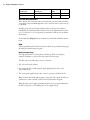
Pin
Description
1-2
+5 V (default)
2-3
+12 V
By default, auxiliary power supply is strapped for +5 V (pins 1-2).
Specifications
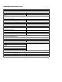
Specifications
Electrical
Form Factor
Operating Voltage and current
Power Consumption1
5 V ±5%
-5 V ±5%
3.3 V ±5%
12 V ±10%
-12 V ±10%
PCI
1.0 A
n/a
n/a
150 mA
75 mA
7.7 W
PC/104-Plus
140 mA
60 mA
1.03 A
15 mA
n/a
5.08 W
1
This number represents the total power consumption of the Matrox Meteor-II board only. It does not include the power consumption of a camera which
draws current through the auxiliary power supply input.
• Input signals in RS-422 format (if available):
- Termination: 100 Ω.
- Input voltage:
➠
Differential range: 200 mV to 14 V.
➠
Common mode range: -7 V to 7 V.
• Output signals in RS-422 format (if available):
- Specified for a 100 Ω load.
- Output voltage:
➠
Differential range: 2 V to 5 V.
➠
Common mode range: 1.5 V to 3 V.
51
52 Appendix B: Technical information
• Input signals in TTL format:
- No termination.
- Input current: ± 1µA.
- Input voltage:
➠
Max of low: 0.8 V.
➠
Min of high: 2 V.
➠
Range: -0.5 V to 5.5 V.
• Output signals in TTL format:
- No termination.
- Output current:
➠
Max of low: -60 mA.
➠
Min of high: 30 mA.
- Output voltage:
➠
Max of low: 0.55 V.
➠
Min of high: 2 V.
Specifications
• Trigger input signal (opto-isolated):
- Termination: 511 Ω series.
- Input current:
➠
Min of low: 0 µA.
➠
Max of low: 250 µA.
➠
Min of high: 5 mA1.
➠
Max of high: 15 mA2.
- Input voltage:
➠
Min of low: 0 V.
➠
Max of low: 0.8 V.
➠
Min of high: 2 V.
➠
Max of high: 5 V.
Environmental
• Min./max. ambient operating temperature: 0°C - 55° C.
• Min./max. storage temperature: -40° C - 75° C.
• Max. altitude for operation: 3000 meters.
• Max. altitude for transport: 12000 meters.
• Operating humidity: 20 - 80% relative humidity (non-condensing).
1. A Min of 6.3 mA recommended.
2. A Max of 10 mA recommended.
53
54 Appendix B: Technical information
Appendix C: Listing
of Matrox Meteor-II
/Multi-Channel
Boards
This appendix lists specific versions and revisions of the
Matrox Meteor-II /Multi-Channel board.
56 Appendix C: Listing of Matrox Meteor-II /Multi-Channel Boards
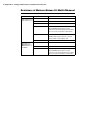
Revisions of Matrox Meteor-II /Multi-Channel
Board
Version
Description
Matrox Meteor-II
/Multi-Channel for PCI
751-00 rev. A
Original version.
751-01 rev. A
No functional change.
751-02 rev. A
No functional change.
751-0201 rev. A
No functional change.
Note that MJPEG module support has been
removed for some boards with this revision number.
This is due to the discontinuation of this module.
751-03 rev. A
VMChannel removed.
MJPEG module support removed for all boards.
Board now fits in a half-length PCI slot.
Matrox Meteor-II
/Multi-Channel for
PC/104-Plus
751-0301 rev. A
No functional change.
886-00 rev. A
Original version.
886-00 rev. B
No functional change.
886-01 rev. A
Replaced expansion connectors (for 896-01).
Note that MJPEG module support has been
removed for some boards with this revision number.
This is due to the discountinuation of this module.
Appendix D:
Glossary
This appendix defines some of the specialized terms used
in this Matrox Meteor-II document.
58 Appendix D: Glossary
• ASIC
Application-specific integrated circuit. An integrated circuit custom-made to meet
the requirements of a specific application. It integrates several digital and/or analog
functions into a single die. This results in a reduction in cost, board area, and
power consumption, while improving performance when compared to an
equivalent implementation using off-the-shelf components.
• Band
One of the surfaces of a buffer. A grayscale image requires just one band. A color
image requires three bands, one for each color component.
• Bandwidth
A term describing the capacity to transfer data. Greater bandwidth is needed to
sustain a higher transfer rate. Greater bandwidth can be achieved, for example, by
using a wider bus.
• Bit
A digit of a binary number. Images are described as 1-bit, 8-bit, 16-bit, etc. The
numbers indicate the bits available to store the value of each pixel in the image.
• Bus
A pathway along which signals are sent, generally in two directions, for
communication of data.
• Color component
One of the components that make up a color space. Typically, each component
of a color image is stored in a separate band of a multi-band buffer.
• Color space
A color space is a way of representing and describing the complete range of
perceived colors. A number of color spaces have been developed. Common color
spaces are RGB and HSL. Both describe the same range of perceivable colors.
59
• Composite sync
A synchronization signal made up of two components: one horizontal and one
vertical.
• DCF
Digitizer Configuration Format. A DCF defines the input data format and among
other things, how to accept or generate video timing signals such as horizontal
sync, vertical sync, and pixel clock.
• Display memory
See frame buffer.
• Exposure time
Refers to the period during which the image sensor of a camera is exposed to light.
As the length of this period increases, so does the image brightness.
• Field
One of the two halves that make up an image. One half consists of the image's
odd lines (known as the odd field); the other half consists of the image's even lines
(known as the even field).
• Frame
A single image grabbed from a video camera.
• Frame buffer
A frame buffer is a dedicated storage area often used for data transfers between
devices of differing speeds. For example, since a computer sends out data faster
than a screen can display it, the data is temporarily stored in the frame buffer. The
buffer is generally thought of as a two-dimensional surface with a certain pixel
depth.
60 Appendix D: Glossary
• Grab
To acquire an image from a camera.
• Horizontal sync
The part of a video signal that indicates the end of a line and the start of a new one.
See also vertical sync.
• HSL
A color space that represents color using components of hue, saturation, and
luminance. The hue component describes the actual color of a pixel. The
saturation component describes the concentration of that color. The luminance
component describes the combined brightness of the primary colors.
• Host
In general, Host refers to the principal CPU in one’s computer.
• Interlaced scanning
Describes a transfer of data in which the odd-numbered lines of the source are
written to the destination buffer first and then the even-numbered lines (or
vice-versa).
See also progressive scanning.
• Latency
The time from when an operation is started to when the final result is produced.
• Live processing
See real-time processing.
61
• LUT mapping
Look-up table mapping. A point-to-point operation that uses a table to define a
replacement value for each possible pixel value in an image.
• MSPS
Mega Samples per second.
• PCI
Peripheral Component Interconnect. Present day standard expansion bus.
• PCI Primary/Secondary Bus
A high-performance bus that provides a processor-independent data path between
the CPU and high-speed peripherals.
• PLC
Programmable Logic Controller. A device used to automate monitoring and control
of industrial plants. It can be used as a stand-alone device or in conjunction with
data acquisition.
• Progressive scanning
Describes a transfer of data in which the lines of the source input device are written
sequentially into the destination buffer.
Also known as non-interlaced. See also interlaced scanning.
• Real-time processing
The processing of an image as quickly as the next image is grabbed.
Also known as live processing.
62 Appendix D: Glossary
• Reference levels
The zero and full-scale levels of an analog-to-digital converter. Voltages below a
black reference level are converted to a zero pixel value; voltages above a white
reference level are converted to the maximum pixel value. Together with the analog
gain factor, the reference levels affect the brightness and contrast of the resulting
image.
• RGB
A color space that represents color using the primary colors (red, green and blue)
as components.
• Synchronous function
A function that does not return control to the caller until it has finished executing.
See also asynchronous function.
• Vertical sync
The part of a video signal that indicates the end of a frame and the start of a new
one.
See also horizontal sync.
• VIA
Video Interface ASIC. A custom ASIC that connects all the data buses on the board
(grab and PCI bus) to one another, and directs and monitors data flow "traffic".
It is a video interface that provides various ways of inputting and outputting data.
Index
A
H
A/D converters 32
acquisition features 30
ActiveMIL 10
auxiliary power supply 22, 35, 49–50
hardware
connecting external devices 21
PCI slot 11, 39
reference 30
heat sink 17, 26
C
cameras
grabbing images 27
multi-tap 35
number of cameras per board 27
connectors
auxiliary power supply 21–22, 49
video input 21–22, 46
D
data interfaces
PCI interface 36
VIA 35
data transfer 9
DMA memory 39
I
input channels 31
installation
multiple boards
PC/104-Plus 26
PCI and Compact PCI 26
overview 12
PC/104-Plus form factor 18
PCI form factor 16
IRQ conflicts 40
L
lookup table 35
low-pass filter 31
E
M
electrical specifications 51
environmental specifications 53
master mode 33
Matrox 4Sight-II 20
Matrox Inspector 10
Matrox Intellicam 10
Matrox Meteor-II package
optional items 11
standard package 11
MIL 9
MIL-Lite 9
mode
master 33
slave 33
monochrome 30
multiple Matrox Meteor-II boards
grabbing 27
PCI bandwidth 26–27
multi-tap cameras 35
G
gain 31
grab section
A/D converters 32
gain control 31
input channels 31
lookup table 35
low-pass filter 31
performance 31
phase-locked loop 32
PSG 32
trigger 33
UART 34
user bits 35
grabbing from multiple boards 27
O
V
optional items
DBHD44-TO-8BNC cable 11
MIL 11
MIL-Lite 11
VIA 9, 35
VIA’s PCI port 36
video formats supported
monochrome 8, 30
RGB 8, 30
video input connector
pinout 46
video transfer memory 9, 35, 44
voltage and current specifications 51
P
PC/104-Plus board for Matrox 4Sight-II 20
PCI
bandwidth 26
slot 39
PCI slot 11
phase-locked loop 32
pinouts
camera power supply connector 49
video input connector 46
PSG 32
R
RGB 30
RS-232 serial port 34
S
slave mode 33
software
supported 9
specifications
electrical 51
environmental 53
technical 44
synchronization 33
system requirements 10
T
technical information 44
timing
lines/frame 31
pixels/line 31
sampling rate 31
trigger 33
troubleshooting 38
U
UART 34
user bits 35
Regulatory Compliance
FCC Compliance Statement
Warning
Changes or modifications to this unit not expressly approved by the party responsible for the
compliance could void the user's authority to operate this equipment.
Note
This device complies with Part 15 of FCC Rules. Operation is subject to the following two
conditions:
1. this device may not cause harmful interference, and
2. this device must accept any interference received, including interference that may cause
undesired operation.
This equipment has been tested and found to comply with the limits for a Class A digital device,
pursuant to Part 15 of the FCC Rules. These limits are designed to provide reasonable protection
against harmful interference when the equipment is operated in a commercial environment. This
equipment generates, uses, and can radiate radio frequency energy and, if not installed and used
in accordance with the instruction manual, may cause harmful interference to radio
communications. Operation of this device in a residential area is likely to cause harmful interference
in which case the user will be required to correct the interference at his/her own expense. The user
is advised that any equipment changes or modifications not expressly approved by the party
responsible for compliance would void the compliance to FCC regulations and therefore, the user's
authority to operate the equipment.
Industry Canada Compliance Statement
This digital apparatus does not exceed the Class A limits for radio noise emission from digital
apparatus set out in the Radio Interference Regulations of Industry Canada.
Le présent appareil numérique n'émet pas de bruits radioélectriques dépassant les limites
applicables aux appareils numériques de Classe A prescrites dans le Règlement sur le brouillage
radioélectrique édicté par Industrie Canada.
EU Notice (European Union)
WARNING: This is a class A product. In a domestic environment this product may cause radio
interference in which case the user may be required to take adequate measures
AVERTISSEMENT: Cet appareil est de la classe A. Lorsque cet appareil est utilisé dans un
environnment résidentiel, il peut entraîner des interférences radioélectriques. Dans ce cas, l'usager
peut être prié de prendre des mesures correctives appropriées.
This device complies with EC Directive 89/336/EEC for a Class A digital device. It has been tested
and found to comply with EN55022/CISPR22 and EN55024/CISPR24 when installed in a
typical class A compliant host system. It is assumed that this device will also achieve compliance
in any Class A compliant system.
Le présent appareil numérique répond aux exigences stipulées dans la directive européenne
89/336/EEC prescrite pour les appareils numériques de classe A. Ce produit a été testé
conformément aux procédures EN55022/CISPR22 et EN55024/CISPR24 dans un système hôte
typique et conforme à la classe A. On peut présumer que cet appareil sera aussi conforme s’il est
utilisé dans n’importe quel système de classe A.
Product support
Limited Warranty
Matrox warrants this product against defects in materials and workmanship for a period of one year from
the date of delivery. Matrox and its suppliers expressly disclaim any and all other warranties, express or
implied.
Your sole remedy shall be, repair or replacement of the product provided that the defective product be
returned to the authorized dealer within a year from the date of delivery.
If you wish to return your board, contact the Matrox authorized dealer where you purchased the board
for service. Do not return a product to Matrox without authorization.
In the event you must return the board directly to Matrox, follow these steps:
1. Contact Customer Support (The Customer support contacts information sheet included in your
package has the phone numbers for Matrox's offices).
Customer Support will ask you to describe the problem and will issue a Return Merchandise
Authorization (RMA).
2. Leave the configuration as it was when you were using the board.
3. Pack the board in its original box and return it with a completed "Product Assistance Request"
form (provided in the following page).
Return address
U.S. customers must return their products to our U.S. address:
Matrox International Corp.
625 Route 3 Unit B
Plattsburgh, N.Y.
12901-6530
Canadian and other international customers can return their products directly to our Canadian facility:
Matrox Electronic Systems Ltd.
1055 St. Regis Blvd.
Dorval, Quebec
H9P 2T4
Product Assistance Request Form
Name:
Company:
Address:
Phone:
Fax:
E-mail:
Hardware Specific Information
Computer:
CPU:
System memory:
PCI Chipset:
System BIOS rev:
Video card used:
Resolution:
Network Card:
Network Software:
Other cards in system:
Software Specific Information
Operating system:
Rev:
Matrox SW used:
Rev:
Compiler:
Rev:
Fill out only if you are returning a board
RMA #:
Who were you talking to in customer support?
Date board was received:
Date of failure:
MOD #:
These numbers are on the label at the back of the board.
SER #:
REV #:
PMB #:
PNS #:
Can you reproduce the problem? Yes No
Is an error code displayed? Yes No
If so, what code?
... Continued on reverse
Describe the problem: