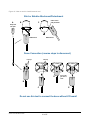
1
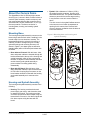
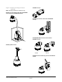
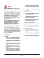
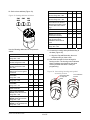
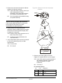
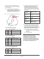
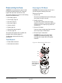
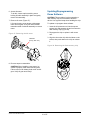
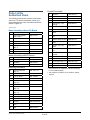
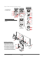
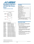
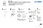
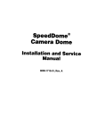
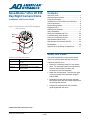
SpeedDome® Ultra VII EIS Day/Night Camera Dome Contents About this Guide ....................................................1 About the Camera Dome .......................................2 Cable Requirements ..............................................7 Install/Removal Tool for Base with I/O Board........8 Power-Up Routine..................................................9 Synchronizing Domes............................................9 Diagnostic LEDs ....................................................9 Warnings and Cautions .........................................9 Indoor Installation.................................................11 Using the Install/Removal Tool ............................20 Troubleshooting Indoor Domes ...........................22 Parts List for Authorized Users ............................32 Specifications-Indoor Dome.................................34 Specifications-23X Camera with EIS ...................35 Declarations .........................................................36 Appendix A: Vicon Wiring Configurations............37 Installation and Service Guide Figure 1. SpeedDome Ultra VII EIS Day/Night Camera Dome Mounting Base Housing Eyeball About this Guide Camera Dome Product Codes Product Description This guide explains how to connect the camera dome to a mounting base and how to service it. RAS918LS DAY/NIGHT, EIS, 60HZ, 23X, NO BASE, BLACK It does not explain how to: RAS918LSP DAY/NIGHT, EIS, 60HZ, 23X, STD BASE, BLACK (RUPTB) RAS918LSI DAY/NIGHT, EIS, 60HZ, 23X, I/O BASE, BLACK (RUIOB) • Determine a mounting location for the camera dome. The mounting location is determined by customer requirements; therefore, this information is provided separately. • Attach the mounting base. There are two types of mounting bases. See information shipped with the base. • Assemble housings and structures used with this camera dome. See information shipped with the housing and structure. • Program the camera dome. See operator's guide shipped with the dome. © 2005 Sensormatic Electronics Corp. SPEEDDOME ULTRA VII EIS DAY/NIGHT CAMERA DOME INSTALLATION AND SERVICE GUIDE 8200-0184-14, REV. A 1 of 37 • Eyeball. With a diameter of 120mm (4.75in), the eyeball contains a camera, tilt motor, and associated electronics. The eyeball enables the camera to pan and tilt to track a target moving in any direction even as it moves under the dome. About the Camera Dome The SpeedDome Ultra VII EIS day/night camera dome (Figure 1) comes in black, mounts indoors or outdoors (with accessory outdoor enclosure), and can communicate with the video controller over a SensorNet 485, RS-422, Manchester, or UTC (upthe-coax) network. The dome consists of a mounting base, housing, and rotating eyeball assembly. Two slot covers in the eyeball facilitate access to the camera, one of which incorporates an opening for the camera lens. Remove both covers to improve ventilation when the dome is to be used outdoors. Mounting Base Figure 2. Mounting base and housing and eyeball assembly The housing and eyeball assembly connects to the base using a twist and lock action, enabling it to be moved easily from one location to another. The base attaches directly to a hard or tile ceiling, or indirectly to walls or ceilings using one of many optional housings and mounting structures. As shown in Figure 2, two base types are offered: a standard base (without I/O board) and a base with I/O board. Base without I/O Board Base with I/O Board • Base without I/O board. With this base, video, data, and power cables are inserted through the base and attached to the top of the housing and eyeball assembly, which is then connected to the base. A lanyard connects between the base and the housing and eyeball assembly to prevent cables from being pulled during disassembly. • Base with I/O Board. With this base, video, data, and power cables are pre-connected to an I/O PC board. A spring-finger connector on the board makes electrical contact with the housing and eyeball assembly as it connects to the base. Housing and Eyeball Assembly The housing and eyeball assembly consists of the following: • Housing. The housing contains the dome's power supply, pan motor, and electronics used to operate the eyeball. The housing provides one alarm input and one alarm output using the base without I/O board, or four alarm inputs and four alarm outputs using the base with I/O board. SPEEDDOME ULTRA VII EIS DAY/NIGHT CAMERA DOME INSTALLATION AND SERVICE GUIDE 8200-0184-14, REV. A 2 of 37 Electrical Box in Ceiling Indoor Ceiling Mounting Using hardware shipped with the base, the camera dome attaches directly to indoor ceilings made of sheet rock, wood, metal, or concrete (Figure 3). RHIU3X3 Figure 3. Surface mounting to hard ceilings RHIU4X4 3 X 3 mounting plate Attaches dome to a standard 3.5 x 3.5 duplex electrical box. CAUTION: Do not use the same electrical box used for line voltage mains. 4 X 4 mounting plate Attaches dome to a standard 4 x 4 duplex electrical box. CAUTION: Do not use the same electrical box used for line voltage mains. * Option in white, but can be painted to match decor. † Top hat housing/dome assembly also mounts to structure. Tile Ceilings RHIUFB RHIUAB Indoor Ceiling/Wall Mounting (Optional) RHIU2X2M* The camera dome attaches to one of the following optional indoor mounting structures (Figure 4). RHIU2X2P* Sheet Rock, Concrete, Plaster or Wood Ceilings RHIUTH RHIUHC RHIUFB RHIUPNDT† Top hat housing with trim ring This housing attaches to a ceiling or to most indoor mounting structures. A trim ring and optional magnetic bubble provide concealment. Optional bubbles: RUCLR (clear), RUSLV (silver), RUSMK (smoked), or RUGLD (gold). Dome base included. Hard ceiling bracket Enables top hat housing to be recessed in ceiling (requires top hat RHIUTH). Can be installed from below ceiling. Fixed bracket Enables top hat housing to be recessed in ceiling (requires top hat RHIUTH). Requires access from above ceiling. Pendant mount Suspends dome from a hard ceiling with 3.2cm (1 1/4in) NPT pipe fittings. Fixed bracket Enables top hat housing to be recessed in a 2x2 tile (requires top hat RHIUTH). Adjustable bracket Enables top hat housing to be recessed in a 2x4 tile (requires top hat RHIUTH). 2 X 2 metal tile mount Enables top hat housing to be recessed in 2x2 openings (includes top hat housing). 2 X 2 metal tile pendant mount Enables dome to be suspended from 2x2 openings. Requires 3.2cm (1 1/4in) NPT pipe (allow 3m (10ft) max. length) Accepts the following housings: RHIOTH, Dome base. * Option in white, but can be painted to match decor. † Top hat housing/dome assembly also mounts to structure. Wall Mounting RHIUCM* RHIULWM*† Wall mount with corner feature Enables dome to attach to a flat wall, inside corner, or outside corner. Long 0.6m (24in) wall mount Positions dome away from wall to enable it to see over furniture, shelving, and displays. This mounting structure attaches to the flat wall, inside corner, or outside corner. * Option in white, but can be painted to match decor. † Top hat housing/dome assembly also mounts to structure. Structural I-Beams RHIUIB / RHIUIBM† I-beam mount only. Enables dome suspension from an I-beam. RHIUIBM version has all related accessories to suspend from I-beam, except 3.2cm (1 1/4in) NPT pipe. SPEEDDOME ULTRA VII EIS DAY/NIGHT CAMERA DOME INSTALLATION AND SERVICE GUIDE 8200-0184-14, REV. A 3 of 37 Figure 4. Indoor mounting structures (optional) RHIUFB RHIUAB RHIUHC RHIU2X2 RHIU2X2P RHIUIBM RHIUTH ADSDUPIHC ADSDUPIHS ADSDUPIVRC ADSDUPIVRS RHIUTH RD500A ADSDUPIHC ADSDUPIHS ADSDUPIVRC ADSDUPIVRS RHIUTH Vandal Resistant Bubble Vandal Resistant Bubble RD500A RHIUWM RHIUPNDT RHIUCM RHIUTR RHIU3X3 RHIU4X4 RUCLR RUSLV RUSMK RUGLD RHIULWM RHIUTH SPEEDDOME ULTRA VII EIS DAY/NIGHT CAMERA DOME INSTALLATION AND SERVICE GUIDE 8200-0184-14, REV. A 4 of 37 Outdoor Mounting (Optional) SpeedDome Housing Adapter Bracket (Optional) Note: This document does not include outdoor installation and service instructions. For these instructions, see RHODUL Outdoor Housing Install Guide 8200-0492-01. An RHSDA adapter bracket (Figure 6) enables the dome to fit into SpeedDome indoor housings (RD500A). Locking pins in the bracket enable the dome to swing out for servicing or removal. The camera dome attaches to outdoor walls and ceilings using an RHODUL outdoor housing (Figure 5) and an ROENDC end cap connected to one of the following optional mounting structures (Figure 7) • • • • • • Figure 6. RHSDA adapter bracket (to used with the RD500A housing) RHOTR Over Roof Mount RHOTRF Over Roof Floor Mount RHOPN Pendant Mount RHOWPA Pole Mount RHOSW/RHOLW Wall Mount RHOWCA Corner Bracket. The outdoor housing contains a pre-installed mounting base, a cooling fan for hot weather, a heater for cool weather and to prevent icing, and surge protection circuitry. An environmental PC board is used to pre-wire cables. A round spring-finger connector on the board makes electrical contact with the housing and eyeball assembly as it connects to the base. Note: Do not use the I/O board (designed for indoor use) in place of the environmental board. Figure 5. RHODUL outdoor housing (optional) SPEEDDOME ULTRA VII EIS DAY/NIGHT CAMERA DOME INSTALLATION AND SERVICE GUIDE 8200-0184-14, REV. A 5 of 37 ROENDC end cap Figure 7. Outdoor mounting structures (optional). Note: Housing is shown for reference only. RHOTR over roof mount comes with the ROENDC end cap (shown with RHOTRF bracket) RHOWPA pole mount comes with the ROENDC end cap RHOSW/RHOLW wall mount comes with the ROENDC end cap RHOPN pendant mount RHOSW RHOLW RHOWCA corner bracket only (shown with RHOLW mount) SPEEDDOME ULTRA VII EIS DAY/NIGHT CAMERA DOME INSTALLATION AND SERVICE GUIDE 8200-0184-14, REV. A 6 of 37 Note: Typically, distances are used that provide a 15% margin between nominal and low line conditions. For example, if the nominal voltage is 120Vac, restrict cable length to that associated with 100Vac (0.85 x 120). Cable Requirements Data Cable The table below shows requirements for SensorNet, RS-422, and Manchester networks. For more information about communication protocols and cable networks, see Communication Protocols and Cable Networks, 8000-2573-19. Worst-case ac line voltages Data cable requirements SensorNet RS-422 Manchester 1 unshielded, twisted pair* 2 shielded, twisted pair* 1 shielded twisted pair** Wire gauge 22 AWG 22 AWG 18 AWG Connection Nonpolarized Polarized Polarized Max. devices on line 32 10 3 Cable type * Worst-Case Meters AC Power Source Low Line V (Feet) 28 VA 117 180 (600) Transformer 100 130 (430) 5604-0006-01 90 80 (270) 50 VA 117 180 (600) Transformer 100 150 (500) 5604-0044-01 90 90 (300) 1-position SensorNet 117 210 (700) RJ1SNUD 100 130 (430) 90 100 (325) 117 210 (700) 100 130 (430) 90 100 (325) 117 300 (1000) 6-position SensorNet 100 230 (750) Indoor J-Box 90 160 (530) RJ6SN 240 300 (1000) 200 230 (750) 180 160 (530) 10-Position RS-422 117 275 (900) Indoor 120V/60Hz J-Box 100 200 (650) RJ860AP 90 130 (430) 10-Position RS-422 240 275 (900) Indoor 240V/60Hz J-Box 200 200 (650) RJ860AP1 180 130 (430) Universal Transformer 117 200 (650) 0300-0914-01 100 130 (430) 90 90 (300) 240 200 (650) 200 130 (430) 180 90 (300) 1-position SensorNet RJ1SNUD-1 Power, data, and video cables can be ordered separately or within a composite cable that can be ordered in various lengths. Plenum-rated cables must be used in indoor ceilings used for environmental air return (called "other air space" in the National Electrical Code). Order parts through your distribution network. Note: If you order cable from an outside source, wire colors may be different. ** Belden 88760 (plenum), or Belden 8760 cable (nonplenum) cable is recommended. Plenum-rated cables must be used in indoor ceilings used for environmental air return (called "other air space" in the National Electrical Code). Order cable directly from Belden by calling 1-800-235-3361. Power Cable For the camera dome to operate properly, line voltage must not go below the worst-case low line voltage shown in the following table. Make cable lengths as short as possible to minimize affects of low line voltages. As shown in the table, maximum cable length depends on the Class 2 LPS (low voltage) ac source (such as a J-box) and the worstcase low line voltage. These lengths are for Sensormatic composite cables, which use 18 AWG ac power wires. SPEEDDOME ULTRA VII EIS DAY/NIGHT CAMERA DOME INSTALLATION AND SERVICE GUIDE Indoor Dome Universal Transformer 0300-0914-03 8200-0184-14, REV. A 7 of 37 Twisted Pair Adapter Install/Removal Tool for Base with I/O Board Figure 8. Twisted Pair Adapter The install/removal tool (Figure 10) enables you to connect or disconnect the housing and eyeball assembly from the base with I/O board, and to attach/detach skirts and bubbles to a top-hat housing, without the need for a ladder. The tool attaches to a telescopic pole (purchased separately). See page 20. CAUTION: Do not use this tool to connect the dome to the base without I/O board. The supplied ADACTP01BNC Twisted Pair Adapter (Figure 8) is used to transmit video or video with UTC (up-the-coax) dome control signals over unshielded twisted pair (UTP) cables, point-topoint, up to 300m (1000ft). Figure 10. RHIRT indoor install/removal tool The adapter mounts directly to the video source or receiver without additional cabling and uses Category 2-6 twisted pair wires to transmit the video and dome control signals. The adapter does not require power. RHIRT Removal Tool One adapter is supplied. If used, another adapter must be ordered for the connection at the other end of the cable. Figure 9 shows twisted pair cable connections. See installation guide 8200-0298-01 for details. Telescopic Pole 08140 by Recreational Water Products. See page 20 to order. Figure 9. Cabling overview Twisted Pair Adapter (Dome End) American Dynamics Dome or Fixed Camera Twisted Pair Adapter (Fixed Camera End) Cat 2-6 UTP Cable Twisted Pair Adapter (Switcher/Controller End) Video Switcher/ Controller SPEEDDOME ULTRA VII EIS DAY/NIGHT CAMERA DOME INSTALLATION AND SERVICE GUIDE 8200-0184-14, REV. A 8 of 37 Power-Up Routine Warnings and Cautions After power is connected to the dome, the dome performs the following homing routine. Please review the following warnings and cautions before you begin installation or service. 1. After a few seconds, the camera lens tilts up into the housing and eyeball assembly. WARNINGS 2. The lens tilts downs until it looks at the floor. ! 3. Eyeball pans slowly. 4. Lens tilts up 90° (home position). WARNING! ALWAYS USE: Once the lens is in its home position, you can then use the controller to call up the camera and control it. • Proper safety equipment for the location and type of installation. • Proper lift equipment to reach the installation. Synchronizing Domes • Safety features of the lift equipment. To prevent picture rolling when switching from camera to camera, all domes can be synchronized to a 50Hz or 60Hz ac source. A V-phase adjustment at the control console enables the dome to sync to any line phase. BE SURE: • Electrical power is not connected to the dome when connecting wires. Dome will move when power is applied. • Electrical power is not connected to nearby fixtures that you might touch during installation. Diagnostic LEDs ! If a base without I/O board is used, LEDs in the housing and eyeball assembly enable you to check for power and data. WARNING! DO NOT install this camera dome where highly combustible or explosive products are stored or used. If a base with I/O board is used, LEDs on the underside of the mounting base enable you to check for power and data. If an RS-422 network is used, other LEDs on the board indicate that wiring is correct, reversed, open, or grounded. ! WARNING! This dome runs on 24Vac. DO NOT connect line voltage to this dome. North America power requirements: In North America, this device is intended to be supplied from a Class 2 power supply. For outdoor installations, use Class 3 wiring techniques, liquidtight conduit, or liquid-tight pipe. This installation should be made by a qualified service person and should conform to all local codes. SPEEDDOME ULTRA VII EIS DAY/NIGHT CAMERA DOME INSTALLATION AND SERVICE GUIDE 8200-0184-14, REV. A 9 of 37 ! WARNING! EU power requirements: This product runs on 24Vac. In the EU, it is intended to be powered from a Limited Power Source. A limited power source is a certified source of SELV, and if inherently limited, with 8 amps maximum output current, and a maximum of 100VA available; or if not inherently limited, fused with a maximum value of 3.3 Amps, meeting section 2.11 of IEC950, and a maximum of 250VA available. The power supply can be obtained through Sensormatic or through another source where the provider can furnish the verification. This is required to assure electrical safety in the product. Stromanforderungen in der EU: Dieses Produkt wird mit 24 V Wechselstrom betrieben. In der EU ist es für den Betrieb durch eine begrenzte Stromquelle vorgesehen. Eine begrenzte Stromquelle ist eine zertifizierte SELV-Quelle (Schutzkleinspannung), bei inhärenter Begrenzung mit einem maximalen Ausgangsstrom von 8 A und 100 VA maximaler Verfügbarkeit, bei nicht inhärenter Begrenzung mit einer maximalen Sicherung von 3,3 A gemäß Abschnitt 2.11 der IEC950 und 250 VA maximaler Verfügbarkeit. Das Netzteil kann über Sensormatic oder eine andere Quelle bezogen werden, wobei der Anbieter den Nachweis der Konformität bereitstellen sollte. Dies ist zur Gewährleistung der elektrischen Sicherheit des Produktes erforderlich. Do not run data and power cables adjacent to or in the same conduit as line voltage mains power. - SensorNet 485 networks require 22 AWG unshielded cable. Do not exceed 32 devices per cable run. - RS-422 networks require 22 AWG shielded cable. Do not exceed 10 devices per cable run. - Manchester networks require 18 AWG shielded cable. Do not exceed 3 devices per cable run. - Always terminate the dome’s CPU board (JW1), if the camera dome is connected at the end of a cable run or is connected to an I/O base. SPEEDDOME ULTRA VII EIS DAY/NIGHT CAMERA DOME INSTALLATION AND SERVICE GUIDE − Use a jeweler's 2.5mm (0.1in) slotted screwdriver to tighten connector screws. Do not over tighten these screws. − Keep the dust cover to protect contacts should the environmental PC board need to be removed from the housing. When connecting the housing and eyeball assembly to an outdoor housing: − Remove both slot covers to keep the camera from overheating. Note: For further information, see installation instructions shipped with the outdoor housing. If disassembling the dome: − Dome contains electrostatic-sensitive devices! Use a ground strap when handling PC boards. − Once disassembled, parts of housing and eyeball assembly are "extremely fragile" and may break. Use extreme care! − Install a new desiccant bag (Desiccant Bag Kit 0352-0207-02) every time the bubble is removed. Cables - I/O PC board (when used). − If a cable clamp is on this board, remove it, as it could damage cable connectors in the housing during assembly. CAUTIONS When using the base without I/O board and wiring cables directly to the dome, ALWAYS connect the video cable to the dome before you connect the 9-pin cable (which contains power). If you connect the 9-pin cable first, you risk shorting delicate electronics near the connector. 8200-0184-14, REV. A 10 of 37 Connecting to the Mounting Base without I/O Board Indoor Installation This section explains how to connect the housing and eyeball assembly to a: This procedure explains how to connect the housing and eyeball assembly to a mounting base without I/O board. • Mounting base without I/O board (page 11) • Mounting base with I/O board (page 17) ! Items You Will Need 1. Set the dome address (Figure 11). You should have on hand the following tools and parts: Install/Removal tool to attach and detach domes and bubbles without a ladder from mounting bases with I/O boards. Base kit: At the top of the housing are three address switches. From left to right, set the switches to the desired address. For example, for address 166, set SW3 to 1, SW2 to 6, and SW1 to 6). Figure 11. Setting address switches − RUIOB/RUWIOB (base with I/O board), or − RUPTB/RUWPTB (standard base without I/O board). WARNING: Ensure that ac power and electrical signals are off during wire connections! SpeedDome Ultra VII with EIS housing and eyeball assembly, 0101-0120-21. SW3 MSB 0 SW2 9 0 SW1 LSB 9 0 9 Other Preparations To ensure a smooth and successful installation, you must: • Have electrical work comply with latest national electrical code, national fire code, and all applicable local codes and ordinances. • Coordinate work with other trades to avoid interference. • Verify existing site conditions and coordinate with the owner's representative and appropriate utilities as required. • Obtain copies of all related plans, specifications, shop drawings and addenda to schedule and coordinate related work. • Thoroughly review the project to ensure that all work meets or exceeds the above requirements. Bring alleged discrepancies to the attention of the CCTV Project Coordinator. SPEEDDOME ULTRA VII EIS DAY/NIGHT CAMERA DOME INSTALLATION AND SERVICE GUIDE 8200-0184-14, REV. A 11 of 37 Use the following addresses for the protocols shown: PROTOCOL 2. Attach the safety lanyard to the cap on the housing and eyeball assembly (Figure 12). Use the M3x6 screw supplied with the lanyard. SW3 SW2 SW1 AD Manchester, Range: 001—064 0 x x PELCO "P," 4800 baud RS422, Range: 001—099 0 x x Sensormatic, 4800 baud RS-422, Range: 001—063, 065—099 0 x x Sensormatic, RS-422 Address 64 is used for global broadcasts 0 6 4 SensorNet, Range: 001—099 0 x x VICON, 4800 baud RS-422, Range: 001—099 0 x x SensorNet, Range: 100—254 1 x x 2 x x Address 255 is used for global broadcasts 2 5 5 Dept. of Transportation (NTCIP), 4800 baud RS-422, Range: 301—399 3 x x Dept. of Transportation (NTCIP), 9600 baud RS-422, Range: 401—499 4 x x Dept. of Transportation (NTCIP), 19.2K baud RS-422, Range: 501—599 5 x x PELCO "P," 2400 baud RS422, Range: 601—699 6 x x PELCO "P," 9600 baud RS422, Range: 701—799 7 x x 3. WITH POWER OFF, connect the video cable (Figure 13). Reset HITACHI VK-xxxx(E)R camera block from 38.4K to 4800 baud (SpeedDome Ultra VII WITH EIS 0100+ feature only). 8 3 0 a. Connect BNC of video micro coax cable 6003-0170-01 to BNC of video cable. PANASONIC UTC 8 9 0 Tyco UTC 8 9 1 PELCO UTC (Origins, Standard, & Extended) 8 9 3 RS-422, LED diagnostic mode for dome wiring installations without the I/O Board 9 0 0 Manufacturing Use, Range: 901—999 9 x x Figure 12. Attaching safety lanyard Only use this location to secure lanyard. b. Feed cable through access hole in base. SPEEDDOME ULTRA VII EIS DAY/NIGHT CAMERA DOME INSTALLATION AND SERVICE GUIDE c. Press the micro coax connector into the mating receptacle in the top of the housing and eyeball assembly. A firm snap indicates a tight connection. 8200-0184-14, REV. A 12 of 37 4. For the dome at the end of a daisy chain, set termination jumper JW1 on the dome CPU board (Figure 13) to “terminated.” Position of dome in communications line… Between other devices End of communications line b. Connect data and power wires to the 9-pin plug (refer to charts below). c. Insert the plug into the mating receptacle in the top of housing and eyeball assembly. Setting Pins Unterminated Terminated 1-2* 2-3 * Pins 1-2 are closest to 9-pin connector. Note: You may need a small slotted screwdriver to gently pry the jumper loose. Be careful not to damage the underlying PC board. Figure 13. Video cable connection and termination jumper location Manchester data and power connections. Order data cable 88760 (plenum) or 8760 (non-plenum) from Belden by calling 1-800-235-3361. Pin Color Designation 1 White Manchester (–) 2 Black Manchester (+) 3 Black 24Vac 4 Red Ground 5 White 6-9 — 24vac Not used. RS-422/Pelco P data and power connections Micro Coax Cable Termination Jumper JW1 Pin Color Designation 1-2 — 3 Black 24Vac 4 Red Ground 5 White 24Vac 6 Orange RS-422 Data In High (+) 7 Green RS-422 Data In Low (–) 8 Yellow RS-422 Data Out High (+) 9 Brown RS-422 Data Out Low (–) Not used. SensorNet data and power connections 5. Connect the 9-pin plug (data and power) to the 9-pin receptacle (Figure 14). If using a Pelco Coaxitron or Panasonic UTC protocol, no data wires are connected, just power. Pin Color Designation 1 Orange SensorNet (unshielded) 2 Yellow SensorNet (unshielded) 3 Black 24Vac 4 Red Ground 5 White 24Vac 6-9 — Not used. CAUTION: DO NOT connect the 9-pin plug unless you have performed step 3 first! a. Feed cables through the access hole in the base. SPEEDDOME ULTRA VII EIS DAY/NIGHT CAMERA DOME INSTALLATION AND SERVICE GUIDE 8200-0184-14, REV. A 13 of 37 7. Connect the housing and eyeball assembly to the base (Figure 15) by aligning the Cap and Base tabs and then turning clockwise until you hear a click. 6. Connect the 4-pin plug (alarm input/output) to the 4-pin receptacle (Figure 14). a. Feed the cable through the access hole in the base. b. Connect alarm wires to the 4-pin plug (refer to chart below). Figure 15. Connecting housing and eyeball assembly to base (cables and lanyard not shown) c. Insert the plug into the mating receptacle in the top of the housing and eyeball assembly. Note: Align tabs on Cap and Base. Alarm connections Pin Color 1 — +12Vdc 2 — Alarm Out 3 — Alarm In 4 — Common Turn clockwise to latch Designation Figure 14. Cable connections (Manchester requires separate cables for data and power) 8. Apply power and wait a few seconds for the dome to begin its homing routine. The homing routine indicates that address was placed into dome memory and that dome is ready for programming. Note: If the homing routine does not occur or if the dome does not respond to commands, check the cable wiring by referring to the LED response tables in Appendix A. 9-pin plug LEDs CR2, CR3, and CR4 visible through opening. SPEEDDOME ULTRA VII EIS DAY/NIGHT CAMERA DOME INSTALLATION AND SERVICE GUIDE 4-pin plug 8200-0184-14, REV. A 14 of 37 Checking Power and Data for Domes Using the Base without I/O Board Check LEDs to verify that power and data are reaching the dome (Figure 16). IMPORTANT! To view the LEDs, you will need to detach the dome from its base. To prevent damage to the dome, hold the dome by its housing, not its eyeball assembly. 1. If the power LED (CR33) on the I/O board glows green, then ac power is connected. 2. Green CR2, red (CR3), and yellow (CR4) LEDs surround the video connection and are visible through opening. Check that the following communication protocols are properly wired by observing these LEDs. Figure 16. Cable connections (Manchester requires separate cables for data and power) 9-pin plug LEDs CR2, CR3, and CR4 visible through opening. SPEEDDOME ULTRA VII EIS DAY/NIGHT CAMERA DOME INSTALLATION AND SERVICE GUIDE 4-pin plug 8200-0184-14, REV. A 15 of 37 Manchester: After approximately 20 seconds, the three LEDs do the following: Red Green Yellow Blinking Steady, Blinking, then 1 Steady Steady, then Off Blinking Steady, then Blinking Steady Possible Cause 2 White (pin1) and black (pin 2) correctly wired. When the network has been detected. 2 When data for this dome has been received. Thereafter, the yellow LED will flicker when data is sent to this dome. 1 White (pin 1) or white and black (pin 2) wires not connected, or white and black wires shorted. RS-422: Set the domes address switches to 900 test mode, then apply power. After approximately 20 seconds, the three LEDs do the following: 3 Possible Cause Red Green Yellow Control Mostly Off, Blinking On Mostly Off, Blinking On Rapidly Blinking Yes RX+ (pin 6) and RX– (pin 7) correctly wired. Mostly Off, Blinking On Mostly Off, Blinking On Rapidly Blinking No Wire to RX+ (pin 6) not connected. Mostly On, Blinking Off Mostly On, Blinking Off Rapidly Blinking No Wires to RX+ (pin 6) and RX– (pin 7) reversed. Off On Alternating Off and On Every 60 Sec. No Wire to RX– (pin 7) not connected. Wires to RX+ or RX– not connected or shorted together. Wires to RX+ and/or RX– shorted to ac ground. 3 When not in address 900 test mode. When done testing, reset the address switches back to the camera address. SensorNet: After approximately 20 seconds, the three LEDs do the following: Red Green Yellow Control 4 Possible Cause Steady, then Rapidly Blinking Steady, then Off Steady, then Rapidly Blinking Steady, then Off Blinking Steady, then Rapidly Blinking Steady No Wire to pin 2 not connected. Blinking Steady, then Blinking Steady No Wires to pins 1 and 2 shorted together. Wire to pin 1 not connected or both wires to pins 1 and 2 not connected. Blinking Blinking Yes Pins 1 and 2 correctly wired. 4 When data for this dome is received. Thereafter, the yellow LED will flicker when data is sent to this dome. 5 No Wires to pin 1 and/or pin 2 shorted to ac ground. 5 SPEEDDOME ULTRA VII EIS DAY/NIGHT CAMERA DOME INSTALLATION AND SERVICE GUIDE When data for this dome is received. 8200-0184-14, REV. A 16 of 37 RS-422 data connections Connecting to a Mounting Base with I/O Board This procedure explains how to connect the housing and eyeball assembly to a mounting base with I/O board. WARNING: Ensure that ac power and electrical signals are off during wire connections! ! Pin Color Designation 1 Orange RS-422 Data In High (+) 2 Green RS-422 Data In Low (–) 3 Yellow RS-422 Data Out High (+) 4 Brown RS-422 Data Out Low (–) 5-6 — Not used. Referring to Figure 17: SensorNet data connections CAUTION: Detach and discard cable clamp if I/O board has one. If not removed, clamp can damage 9-pin connector in housing and eyeball assembly when you attempt to connect it to base. 1. Set termination jumper JW1 on the dome CPU board to “terminated”. Position of dome in communications line… Between other devices End of communications line Setting Pins Unterminated Terminated 1-2* 2-3 Pin Color Designation 1-4 — 5 Orange SensorNet (unshielded) 6 Yellow SensorNet (unshielded) Not used. Figure 17. Electrical connections * Pins 1-2 are closest to 9-pin connector. Note: You may need a small slotted screwdriver to gently pry jumper loose. Be careful not to damage underlying PC board. 2. Connect video cable (or Twisted Pair Adapter) to BNC connector P8 on I/O board. 3. Connect Manchester, RS-422, or SensorNet 485 data wires to connector P1. If using a Pelco Coaxitron or Panasonic UTC protocol, no data wires are connected, just power. Pin 1 Manchester data connections. Order data cable 88760 (plenum) or 8760 (non-plenum) from Belden by calling 1-800-235-3361. Pin 1 Pin 1 P3 P7 Pin Color 1-4 — Designation P8 Not used. Black Manchester (+) 6 White Manchester (–) Pin 1 P1 JW1 1 5 I/O BOARD P4 JW1 Terminations SPEEDDOME ULTRA VII EIS DAY/NIGHT CAMERA DOME INSTALLATION AND SERVICE GUIDE PINS FUNCTION 1-2 Unterminated 2-3 Terminated 8200-0184-14, REV. A 17 of 37 7. Reattach the I/O board. 4. Connect the alarm output cable, if used, to the P3 connector. Pin Color 1 — 12Vdc (100mA max.) 2 — 12Vdc (100mA max.) 3 — Output P0 (40mA sync. max.) 4 — Output P1 (40mA sync. max.) 5 — Output P2 (40mA sync. max.) 6 — Output P3 (40mA sync. max.) 7 — Ground 8 — Ground 8. Connect power to the base. Designation 9. Check LEDs on the I/O board to verify power and data are reaching the dome (Figure 18). a. The green (ac power) LED glows steadily when ac power is applied. b. For Manchester or SensorNet: The yellow (comm.) LED glows steadily (Manchester) or blinks (SensorNet). If this LED is off, then probably one or both communication wires are open or both are shorted together. For RS-422: Press and hold data test switch SW1 and observe nearby red (CR34) and green (CR35) LEDs; they indicate the following: 5. Connect the alarm input cable, if used, to the P4 connector. Designation Constant green, Blinking red RS-422 line correctly wired. Constant green, No red RS-422 "Data In—" shorted to ac ground. Constant red, Blinking green "Data In +/—" wires reversed. Pin Color 1 — Alarm 3 input (3.5mA sink) 2 — Alarm 2 input (3.5mA sink) 3 — Alarm 1 input (3.5mA sink) 4 — Alarm 0 input (3.5mA sink) Blinking red, Green off "Data In +" shorted to ac ground. 5 — Ground Both LEDs off 6 — Ground "Data In +/—" wires shorted or open. 6. Connect power to P7 connector. Pin Color Designation 1 Black 24 Vac 2 Red Ground 3 White 24 Vac Figure 18. Test switch/LEDs on I/O board Green (CR35) Red (CR34) SW1 RS422 Test Pushbutton Comm. LED Power LED Yellow (CR28) SPEEDDOME ULTRA VII EIS DAY/NIGHT CAMERA DOME INSTALLATION AND SERVICE GUIDE Green (CR33) 8200-0184-14, REV. A 18 of 37 10. Set the dome address (Figure 19). PROTOCOL Figure 19. Setting address switches SW3 MSB 0 SW2 9 0 SW1 LSB 9 0 9 Use the following addresses for the protocols shown: PROTOCOL SW3 SW2 SW1 PELCO "P," 2400 baud RS-422, Range: 601—699 6 x x PELCO "P," 9600 baud RS-422, Range: 701—799 7 x x Reset HITACHI VK-xxxx(E)R camera block from 38.4K to 4800 baud (SpeedDome Ultra VII WITH EIS 0100+ feature only). 8 3 0 PANASONIC UTC 8 9 0 Tyco UTC 8 9 1 PELCO UTC (Origins, Standard, & Extended) 8 9 3 RS-422, LED diagnostic mode for dome wiring installations without the I/O Board 9 0 0 Manufacturing Use, Range: 901—999 9 x x 11. Connect the housing and eyeball assembly to the base (Figure 20). SW3 SW2 SW1 AD Manchester, Range: 001—064 0 x x PELCO "P," 4800 baud RS-422, Range: 001—099 0 x x Sensormatic, 4800 baud RS-422, Range: 001—063, 065—099 0 x x Sensormatic, RS-422 Address 64 is used for global broadcasts 0 6 4 SensorNet, Range: 001—099 0 x x VICON, 4800 baud RS-422, Range: 001—099 0 x x SensorNet, Range: 100—254 1 x x a. Align the Cap and Base tabs, then turn clockwise until you hear a click. 12. Wait a few seconds for dome to begin its homing routine. The homing routine indicates that the address was placed into the dome memory and that the dome is ready for programming. Figure 20. Connecting housing and eyeball assembly to base 2 x x Address 255 is used for global broadcasts 2 5 5 Dept. of Transportation (NTCIP), 4800 baud RS-422, Range: 301—399 3 x x Dept. of Transportation (NTCIP), 9600 baud RS-422, Range: 401—499 4 x x Dept. of Transportation (NTCIP), 19.2K baud RS-422, Range: 501—599 5 x x SPEEDDOME ULTRA VII EIS DAY/NIGHT CAMERA DOME INSTALLATION AND SERVICE GUIDE Note: Align tabs on Cap and Base. Turn clockwise to latch 8200-0184-14, REV. A 19 of 37 TO CONNECT DOME: Using the Install/Removal Tool 1. Insert dome "eyeball down" into tool's receptacle. Fins on dome mate with slots in tool. Use fins to properly align dimple at top of dome with label on tool. CAUTION: Do not use this tool to connect the dome to the standard base (without I/O board) 2. Align label on tool with logo on I/O board in base. Push dome up into place. Used only when the dome is connected to a base having an I/O board, the RHIRT install/removal tool eliminates the need for a ladder during routine service. The tool can be used to: 3. Turn dome clockwise until it clicks. 4. If power is applied, dome should begin its "homing" routine. • Detach skirt or bubble from housing, if used. The skirt or bubble remains attached to the housing during service. 5. Lower pole. • Connect/Disconnect dome from base with I/O board. TO DISCONNECT DOME: • Reattach skirt or bubble. 1. Raise pole and insert dome "eyeball down" into tool's receptacle. Telescopic Pole Required to Use Tool 2. Fins on dome mate with slots in tool. The tool attaches to a telescopic pole that is similar to the type used to clean swimming pools. The pole should be 5 feet-5 inches to 15 feet-5 inches long and have a 1.170 -inch inside diameter to accept the 1.125-inch diameter stem of the tool. If this pole cannot be obtained locally, contact the following manufacturer: 3. Turn dome counterclockwise until it unlocks. 4. Lower pole "vertically" to prevent camera dome from falling out. CAUTION: Turning pole horizontally as it is lowered can cause camera dome to fall out of tool and possibly break on floor. Recreational Water Products 627 E. College Ave. Decatur, GA 33030 5. Remove dome for service. Ask for product code 08140 UPC: 0-14746-58140-2 Procedure Referring to Figure 21, maneuver the stem of the tool into the top of the pole until it snaps in place. TO ATTACH SKIRT OR BUBBLE: Use the tool to push up on the bubble to secure it in place. Magnets secure the bubble. Lower the pole. TO DETACH SKIRT OR BUBBLE: Lifting the pole up at an angle, use one of the hooks on the tool to catch one of the notches at the side of the dome and pull down. The T-lanyard will prevent the skirt or bubble from falling. SPEEDDOME ULTRA VII EIS DAY/NIGHT CAMERA DOME INSTALLATION AND SERVICE GUIDE 8200-0184-14, REV. A 20 of 37 Figure 21. How to use the install/removal tool Skirt or Bubble Attachment/Detachment A B Catch notch and pull down C Snap tool into pole Attachment Detachment Dome Connection (reverse steps to disconnect) Line up Line up D Turn until you feel a click B C E Do not use this tool to connect the base without I/O board! SPEEDDOME ULTRA VII EIS DAY/NIGHT CAMERA DOME INSTALLATION AND SERVICE GUIDE 8200-0184-14, REV. A 21 of 37 Routine Troubleshooting Troubleshooting Indoor Domes Use this procedure if: • Dome does not respond to commands CAUTION: This troubleshooting section is for indoor camera domes only! To troubleshoot outdoor domes, see installation and service manual shipped with the outdoor housing. • Dome does not produce video • Quality of the video is poor • Dome has no lens control. This chapter contains information on: • Routine troubleshooting • Detailed troubleshooting • Disassembling the dome. CAUTION: • DO NOT use this procedure if the dome functions but does not pan or tilt (see step 2 on page 22). IMPORTANT! • If an I/O board is used, use a ground strap when handling the board. When shipping a base having an I/O board, place the dust cover over the spring finger connector to protect it. 1. Try routine troubleshooting first! Use this procedure to isolate the problem without disassembling the housing and eyeball assembly (the base with the I/O board is field repairable). • DO NOT over tighten connector screws on the I/O board; they are delicate. Use a 2.5mm (0.1in) slotted screwdriver. Wider blade widths can damage connectors. CAUTION: DO NOT troubleshoot if the dome functions but does not pan or tilt (see step 2). 2. If you cannot isolate the problem, or the dome functions but does not pan or tilt, contact your sales representative for repair instructions. Procedure 3. If you have no choice but to repair the housing and eyeball assembly. Follow the detailed troubleshooting procedure, but use extreme care. 1. Check video on monitor (a, b, or c). Follow steps until the problem is corrected. a. No video? Go to step 2. b. Contrast or color off? CAUTION: Once disassembled, parts of the housing and eyeball assembly are "extremely fragile" and may break. Proceed using extreme care! YES Contact your sales representative for repair instructions. NO c. Video rolls when switching between monitors? Items You Will Need YES Use the video controller or switcher to synchronize video vertical sync phases of all domes to ac line. For specific instructions, see installation and service manual for the controller or switcher. You should have on hand the following items: • Phillips-head screwdriver • Small slotted screwdriver • 2.5mm (0.1in) slotted screwdriver (for wire connections). Wider blade widths can damage connectors. • Socket wrench with 5in extension and 5.5mm, 6mm, 8mm, and 10mm sockets • 14-18 AWG and 20-22 AWG wire strippers • Install/Removal tool to connect/disconnect dome to indoor bases with I/O boards, and to attach/detach skirts and bubbles—without a ladder. SPEEDDOME ULTRA VII EIS DAY/NIGHT CAMERA DOME INSTALLATION AND SERVICE GUIDE Go to step 2. NO Go to step 2. 2. Check ac power and video connections at Jbox. Are 24Vac and/or video signal absent? YES Correct problem at J-box. NO Go to step 3. 8200-0184-14, REV. A 22 of 37 3. Detach dome from base and examine address switches. Are they set correctly? Figure 22. I/O board connector and jumper locations YES If dome still doesn't respond, contact your sales representative for repair instructions. If you must repair the dome, see "Detailed Troubleshooting", next. NO Set correct address and reattach housing and eyeball assembly. Steps 4-9 are only for bases with I/O boards! If the mounting base DOES NOT contain an I/O board, stop here and contact your sales representative for repair instructions. 4. Isolate problem to housing and eyeball assembly or base by attaching dome to another base with I/O board. Does dome display video or respond to commands? Pin 1 Pin 1 Pin 1 YES Problem is likely cable connections or I/O board if used. Go to step 5. P3 P7 P8 NO Contact your sales representative for repair instructions I/O BOARD Pin 1 P1 JW1 1 5. Verify coaxial video cable is securely connected to coax of I/O board (Figure 22). Is cable disconnected? P4 YES Connect cable. NO Go to step 6. JW1 Terminations PINS FUNCTION 1-2 Unterminated 2-3 Terminated 6. Observe green power LED on I/O board (Figure 21). Is green LED off or not on steady? YES Verify 24Vac cable is properly attached. If OK, replace I/O board or contact your sales representative for repair instructions. NO Go to step 7. P7 Connector (AC in) SPEEDDOME ULTRA VII EIS DAY/NIGHT CAMERA DOME INSTALLATION AND SERVICE GUIDE Pin Color Designation 1 Black 24 Vac 2 Red Ground 3 White 24 Vac 8200-0184-14, REV. A 23 of 37 7. Observe yellow comm. LED (CR28) on I/O board (Figure 23). Is the LED on or flashing? YES Go to step 8. NO Verify cable is properly attached by referring to table in step 9, page 17. If OK, replace I/O board or contact your sales representative for repair instructions. Figure 23. I/O board switch and LED locations SW1 RS-422 Test Pushbutton 8. If using RS-422 network and an I/O board is used, check comm. line connections by pressing and holding data test switch SW1 (Figure 23) and observing nearby red (CR34) and green (CR35) LEDs. These LEDs indicate the following: Constant green, Blinking red Comm. line correctly wired. Constant green, No red "Data In -" shorted to ground. Constant red, Blinking green "Data In +/ -" wires reversed. Blinking red, Green off "Data In +" shorted to ground. Both LEDs off "Data In +/ -" wires shorted or open. Comm. LED Power LED 9. Check spring finger connector on I/O board by connecting housing and eyeball assembly to original base to verify contact between spring fingers and CPU board (under cap). Does dome produce video and respond to commands? P1 connector (Manchester data) Pin Color 1-4 YES Spring fingers may not have seated properly. Reconnect housing and eyeball assembly. Designation Not used. 5 Black Manchester (+) 6 White Manchester (–) NO If routine troubleshooting did not solve the problem, the manufacturer strongly recommends you contact your sales representative for repair instructions. P1 connector (RS-422 data) Pin Color 1 Orange RS-422 Data In High (+) 2 Green RS-422 Data In Low (–) 3 Yellow RS-422 Data Out High (+) 4 Brown RS-422 Data Out Low (–) 5-6 — Replace I/O board. Designation If you must perform detailed troubleshooting, use extreme care when disassembling parts! See "Detailed Troubleshooting," next. Not used. P1 connector (SensorNet 485 data) Pin Color Designation 1-4 — 5 Orange SensorNet 485 6 Yellow SensorNet 485 Not used. SPEEDDOME ULTRA VII EIS DAY/NIGHT CAMERA DOME INSTALLATION AND SERVICE GUIDE 8200-0184-14, REV. A 24 of 37 Detailed Troubleshooting Procedure Use this procedure to determine if the problem is a simple cable connection or a major component. 1. Match symptom to one of the following criteria: − Dome functions but does not pan To perform this procedure, you must open the housing and eyeball assembly. Refer to "Disassembling the Dome" on page 26. − Dome functions but does not tilt − Dome does not "home" or respond to commands even when attached to another dome's base and its address switches are set correctly (dead dome). CAUTION: • DO NOT use this procedure if the dome functions but does not pan or tilt (see step 2 on page 22). 2. Choose a, b, or c to determine if problem is a cable connection or major component. • If routine troubleshooting did not solve the problem, the manufacturer strongly recommends you contact your sales representative for repair instructions. If you must perform detailed troubleshooting, use extreme care when disassembling parts! • When shipping a base with I/O board, place the dust cover over the spring fingers to protect them. a. Dome functions but does not pan. On CPU board, is pan motor ribbon cable attached to connector P4 and is metal side of its fingers towards contacts of connector? YES Replace CPU board. If this doesn't work, replace pan motor. NO Connect cable(s). b. Dome functions but does not tilt. • Delicate connector screws on I/O board. DO NOT over tighten them! Use a 2.5mm (0.1in) slotted screwdriver. Wider blade widths can damage connectors. On camera/lens board, is tilt motor cable attached to connector J3? Is slip ring cable attached to connector J2? • Dome contains electrostatic-sensitive PC boards. Use a ground strap when handling boards. YES Replace camera/lens board. If this doesn't work, replace tilt motor. NO Connect cable(s). c. Dome does not "home" or respond to commands (dead dome). On CPU board, is power supply cable attached to connector P3? Is slip ring cable attached to connector P2? YES Replace CPU board. If this doesn't work, replace power supply board. NO SPEEDDOME ULTRA VII EIS DAY/NIGHT CAMERA DOME INSTALLATION AND SERVICE GUIDE Connect cable(s). 8200-0184-14, REV. A 25 of 37 Disassembling the Dome Removing the CPU Board CAUTION: Once disassembled, parts of dome housing and eyeball assembly are "extremely fragile" and may break. Use extreme care! CAUTION: Electrostatic-sensitive device. Use a ground strap when handling CPU board. This section explains how to remove the following parts from the camera dome. 1. Remove cap. Referring to Figure 24. Remove three Phillips-head screws holding cap, then "gently" lift cap to one side. • CPU board, page 26 • Power supply, page 26 2. Detach connectors. • Pan motor, page 27 On CPU board, detach 8-pin power supply cable from connector P1, pan motor cable from connector P8, and 14-pin slip ring cable from connector P2. • Slot covers, page 27 • Camera, page 28 • Eyeball, page 29 3. Remove CPU board. • Camera/Lens board, page 29 Push your finger through large finger connector hole in cap to pop out CPU board. • Tilt motor, page 30. 4. Reverse steps to reassemble. This section also explains how to update and reprogram dome software (page 31). CAUTION: Do not to pinch wires! When inserting CPU board into housing, avoid pinching power supply cable wires against standoffs. To order parts (authorized users only), see page 32. Tools Required • Phillips-head screwdriver. Figure 24. Removing the CPU board • Small slotted screwdriver. P2 P8 P1 Metal fingers of ribbon cable must face contacts of connector. SPEEDDOME ULTRA VII EIS DAY/NIGHT CAMERA DOME INSTALLATION AND SERVICE GUIDE 8200-0184-14, REV. A 26 of 37 Removing the P/S Board Removing the Pan Motor CAUTION: Electrostatic-sensitive device. Use a ground strap when handling power supply board. Referring to Figure 26. Referring to Figure 25. 1. Perform procedure "Removing the CPU Board" (page 26). 1. Perform procedure "Removing the CPU Board" (page 26). 2. Perform procedure "Removing the P/S Board" (page 26). 2. Remove metal shield. 3. Remove pan motor. Lift motor housing up as shown (1) to disengage motor from pan gear. Then pull motor bracket towards outside of housing (2) to remove. Remove three standoffs holding metal shield, gently remove power supply cable grommet from shield, then "gently" lift shield out of housing. 4. Reverse steps to reassemble. CAUTION: Do not pull delicate cables attached to power supply board. CAUTION: When putting in a new motor, be careful to properly mesh motor and pan gears! Failure to do so can destroy both motor and pan gear. Verify pan gear turns freely! 3. Detach fan motor cable. Cable connects to connector CN3 on power supply board. 4. Remove power supply board. Figure 26. Removing the pan motor Remove three standoffs, then remove power supply board from housing. 5. Reverse steps to reassemble. Pan Motor (lift up, then out) 1 2 Figure 25. Removing the P/S board SPEEDDOME ULTRA VII EIS DAY/NIGHT CAMERA DOME INSTALLATION AND SERVICE GUIDE 8200-0184-14, REV. A 27 of 37 Removing the Slot Covers Removing the Camera 1. Gently swivel eyeball to totally expose one of two slot covers (Figure 27). 1. Perform procedure "Removing the Slot Covers" (page28). CAUTION: Swiveling fast can damage gears. 2. Remove ribbon cable from camera (Figure 28). Swivel camera yoke to expose camera connector. Then, using a small slotted screwdriver, 1) gently pry camera connector loose from camera, and 2) pull it down through cable tie wrap. 2. Insert small, thin-bladed screwdriver into space between cover and eyeball. 3. Gently pry off slot cover. 4. Gently swivel eyeball to totally expose remaining slot cover. With other cover removed, this cover can be easily removed. Figure 28. Removing the ribbon cable Figure 27. Removing slot covers 1 2 3. Remove camera (Figure 29). 1) Loosen the screw holding the camera tripod mount and then 2) carefully lift the camera out. Figure 29. Removing the camera 2 1 Reverse steps to reassemble. Ensure ribbon cable pins are inserted "face down". SPEEDDOME ULTRA VII EIS DAY/NIGHT CAMERA DOME INSTALLATION AND SERVICE GUIDE 8200-0184-14, REV. A 28 of 37 Detaching the Eyeball Removing the Camera/Lens Board 1. Perform procedure "Removing the Slot Covers" (page 28). 1. Perform procedure "Removing the Slot Covers" (page 28). 2. Perform procedure "Removing the Camera" (this page). 2. Perform procedure "Removing the Camera" (page 28). 3. Detach eyeball from housing (Figure 30). 3. Perform procedure "Detaching the Eyeball" (page 29). a. Turn yoke to access tabs. One tab is more accessible than the other. Use your finger to press this tab while, simultaneously, using a small slotted screwdriver to press the other. 4. Separate yoke brackets (Figure 32). Figure 32. Separating the yoke brackets b. While pressing tabs, push up on eyeball to detach it. Figure 30. Loosening the eyeball 5. Gently pry off yoke bracket covering camera/lens board to access bearing assembly (Figure 33). Figure 33. Removing the yoke brackets 4. Detach slip ring connector (Figure 31). Figure 31. Detaching the eyeball SPEEDDOME ULTRA VII EIS DAY/NIGHT CAMERA DOME INSTALLATION AND SERVICE GUIDE 8200-0184-14, REV. A 29 of 37 The following steps refer to Figure 34. Removing the Tilt Motor 6. Access camera/lens board. 1. Perform procedure "Removing the Slot Covers" (page28). To do this, loosen captive retaining screw holding bearing assembly in place and remove this assembly. 2. Perform procedure "Removing the Camera" (page 28). 7. Remove cables from camera/lens board. 3. Perform procedure "Detaching the Eyeball" (page 29). a. Small amber ribbon cable is from tilt motor. Unplug this cable from connector J3 on camera/lens board. 4. Separate yoke brackets (Figure 35). b. Large gray ribbon cable is from slip ring connector. Unplug this cable from connector J2 on camera/lens board. Figure 35. Separating the yoke brackets DO NOT unplug small white ribbon cable from connector J1. 8. Push out on three prongs to detach camera/lens board. 9. Reverse steps to reassemble. Figure 34. Removing the camera/lens board Prongs (3) DO NOT unplug cable from J1. J3 (Pins on ribbon cable must face contacts on connector.) 5. Gently pry off yoke bracket covering pan gear assembly to access tilt cable assembly (Figure 36). Figure 36. Removing the yoke brackets Camera/Lens Board Bearing Assembly SPEEDDOME ULTRA VII EIS DAY/NIGHT CAMERA DOME INSTALLATION AND SERVICE GUIDE 8200-0184-14, REV. A 30 of 37 6. Access tilt motor. Updating/Reprogramming Dome Software To do this, loosen captive retaining screw holding tilt cable assembly in place and gently remove this assembly. CAUTION: This procedure involves extracting a flash memory chip, an electrostatic-sensitive device. Use a ground strap when handling the chip. 7. Remove tilt motor (Figure 37). Lift motor housing up as shown to disengage motor from tilt gear. Then pull motor bracket towards outside of cable/tilt assembly to remove motor. To update or reprogram dome software: 1. Insert the chip extractor tool into the square access hole and squeeze the tool to extract the flash memory chip (Figure 38). 2. Reprogram the chip or replace it with a new one. Figure 37. Removing the tilt motor 3. Align the dot on the chip with the indent on the socket; then push down on the chip to reinsert it. Tilt Motor (Lift up, then out.) Figure 38. Removing the flash memory chip 8. Reverse steps to reassemble. CAUTION: When installing a new motor, be careful to properly mesh motor and tilt gears! Failure to do so can destroy both motor and tilt gear. Verify tilt gear turns freely! SPEEDDOME ULTRA VII EIS DAY/NIGHT CAMERA DOME INSTALLATION AND SERVICE GUIDE 8200-0184-14, REV. A 31 of 37 Eyeball Assembly Parts List for Authorized Users 27 Tilt Motor 3501-0018-01 28 Slot Cover (No Lens)* 0500-8037-01/-02 The following parts can be ordered by authorized users only. To become authorized, contact your sales representative. Parts in the tables below are shown in Figure 39. 29 Yoke, Camera 0500-7258-01 30 Camera/Lens PC Board 0301-0953-01 31 Bearing Assy., Lens Carriage 2510-0038-01 Parts lists 32 Yoke Bracket (Qty. 2 †) 0500-8038-01/-02 33 Cable Assy., Tilt 0650-1680-01 34 Camera, Color, 22x, NTSC 2003-0037-41 Camera, Color, 22x, PAL 2003-0037-42 Base Assembly without I/O Board 1 Mounting Base 0400-1146-01/-02 2 Video Cable Adapter, BNC to Micro 6003-0170-01 35 3 Plug, 4-Pin 2109-0572-04 36 Camera, B&W, 22x, EIA 2003-0037-43 4 Plug, 9-Pin 2109-0572-09 37 2003-0037-44 5 Lanyard 0500-8019-01 Camera, B&W, 22x, CCIR 6 Screw, PH, M3X6 (Qty. †) 5801-1041-111 38 Camera, Color, 23x, NTSC 2003-0046-11 7 Washer, Ext. Tooth, M3 5851-0200-041 39 2003-0046-12 8 Clip, Lanyard 0500-8046-01 Camera, Color, 23x, PAL 40 Camera, Color, 23X, with EIS 2003-0052-01 41 Washer, Flat 2848-8100-08 42 Screw, 1/4-20 x 1/2 2804-7106-07 43 Screws, M2x3 (Qty. 4 †) 5801-0011-120 44 Tripod Mount 0500-6712-01 45 Slot Cover with Lens* 0400-1178-01/-02 Base Assembly with I/O Board 9 Mounting Base 0500-7257-02/-03 10 Ground Clip 0500-7293-01 11 I/O Board 0301-0546-01 12 Video XCVR BNC ADACTP01BNC Housing Assembly 13 Screws, M3x8 PHP (Qty. 3†) 5801-1071-111 * Items 28 and 44 are supplied with the final assembly, not the eyeball assembly. 14 Cap 0500-8021-02/-03 † Item shipped in quantities of one. Order the quantity required. 15 CPU PC Board 0301-1548-03 16 Fan Cable Assy. 0650-2001-01 17 Standoff, M3x8Hx13L (Qty. 3†) 5899-0055-01 18 Fan Plate 0500-9850-02 19 Screw, Thdcut, M3.5 (Qty. 2 †) 5899-0007-01 20 Standoff, M3x6Hx19L (Qty. 3 †) 5887-1122-020 21 Power Supply PC Board 5606-0015-03 22 Slip Ring Assy. 2100-0005-01 23 Pan Motor 3501-0017-01 24 Housing 0500-7255-02/-03 25 Bearing Assy., Pan Gear 2510-0040-01 26 Skirt 0500-6710-02 SPEEDDOME ULTRA VII EIS DAY/NIGHT CAMERA DOME INSTALLATION AND SERVICE GUIDE 8200-0184-14, REV. A 32 of 37 Figure 39. Base, housing, and eyeball assembly Standard Base Assembly* * RUPTB/RUWPTB ** RUIOB/RUWIOB Housing Assembly (0404-0078-03/-04 Base Assembly with I/O Board** 13 14 9 1 2 10 3 11 15 16 17 4 18 5 12 6 7 8 19 20 21 Housing and Eyeball Assy. Assy. SpeedDome Ultra VII only (0101-0041-xx) SpeedDome Ultra VII with EIS only (01010120-21) 22 23 24 25 26 28 27 29 30 33 31 Eyeball Assy. (0404-0079-xx) -01 Color 22X NTSC camera (BLK) -02 Color 22X PAL camera (BLK) -03 B&W 22X EIA camera (BLK) 34-40 -04 B&W 22X CCIR camera (BLK) -05 Color 22X NTSC camera (WHT) 41 -06 Color 22X PAL camera (WHT) -11 Color 23X NTSC camera (BLK) 42 -12 Color 23X PAL camera (BLK) -15 Color 23X NTSC camera (WHT) - 29 Color 23X NTSC EIS camera (BLK) 32 44 43 45 SPEEDDOME ULTRA VII EIS DAY/NIGHT CAMERA DOME INSTALLATION AND SERVICE GUIDE 8200-0184-14, REV. A 33 of 37 Electrical Specifications-Indoor Dome Input Voltage ................................... 18-30Vac, 50/60 Hz Operational NEC Class 2 LPS Design Tolerance ............................ 16-36Vac, 50/60 Hz Pan/Tilt: Manual Pan Speed.................... 0.2°-100° per second Power Consumption........................................16W max. (scaled to zoom position) Current ..........................................................0.85A max. Manual Tilt Speed ................... 0.25°-100° per second Allowable Drop Out .............................................. 100ms (scaled to zoom position) Power On In-Rush Current...................................... 1.5A Preset Pan/Tilt Speed .......220° per second maximum Surge Protection: Pan Travel.............................360° continuous rotation Video Output .........................Low capacitance Zener suppressor 6.5V, 1500W Tilt Travel .............................................................>90° Power Line ............................TVS rated at 60V, 1.5 joules, 250A 8/20µs impulse Pan/Tilt Accuracy ................................................±0.5° 23X (Day/Night) Camera Zoom Functions: RS-422..................................TVS rated at 9.8V/1A, 20V/25A, 500W, 8/20µs impulse Optical Zoom.........................................................23X Digital Zoom ..........................................................10X Manchester/ SensorNet 485 ......................Gas discharge tube rated at: 8/20µs impulse discharge current of 10kA, ten 8/20µs impulse discharge current of 5kA Isolation transformer coupled 2000Vrms. PTC fuse protects transformer. TVS rated at 9.8V/1A, 20V/25A, 500W, 8/20µs impulse Zoom Pause................. 23X selectable or 35X default Total Zoom ..........................................................230X Zoom Stop ........ 46X, 69X, 92X (default), 115X, 138X 161X, 184X, 207X, 230X Zoom/Focus Accuracy ...................................... ±0.5% Auto Synchronization: Line Locked....................Remote V-phase adjustment Internal .....................................Built-in sync generator Alarm Input............................TVS rated at 9.8V/1A, 20V/25A, 500W, 8/20µs impulse Address Range ...................................................... 1-255 Quick View™ Access Time......<1 second to position. Full zoom in <4 seconds. Focus on VM16, VM32 and VideoManager systems is <1 second. Focus on VM96 and RV2715 systems is <7 seconds Alarms Inputs/Control Outputs: When no I/O board is used: Inputs ................................1 dry contact/3.5mA sink Outputs .................................1 open collector driver @ 12Vdc, 40mA When I/O board is used: Programmable Patterns..........Up to 16 depending on host Inputs ..............................4 dry contacts/3.5mA sink Outputs ...............................4 open collector drivers Program Storage ....................256 Kbytes of Flash memory @ 12Vdc, 40mA Data Storage ..........................128 Kbytes of SRAM Environmental Menu Languages ....................English, French, German, Spanish, Italian, and Portuguese Operating Temperature....... –10° to 50°C (14° to 122°F) Relative Humidity ................. 0 to 95% non-condensing Storage Temperature ...............................–20°C to 65°C (–4°F to 149°F) SPEEDDOME ULTRA VII EIS DAY/NIGHT CAMERA DOME INSTALLATION AND SERVICE GUIDE 8200-0184-14, REV. A 34 of 37 Mechanical Eyeball Diameter ........................................ 12cm (4.7in) Specifications-23X Camera with EIS Weight: Type ........................... Interline transfer 1/4in CCD array Height ......................................................... 20.8cm (8in) Housing and Eyeball ............................. 1.36kg (3 lbs) Scanning Area................................ 3.2 (H) x 2.4 (V) mm Base (standard) ............................... 0.09kg (0.20 lbs) Scanning System ........................................ 2:1 interlace Base (with I/O board) ....................... 0.16kg (0.35 lbs) Video Out .......................... 1.0 Vp-p/75 ohms composite Lens and Bubble Densities Signal-to-Noise.........................................50 dB (typical) Eyeball Lens ................................................................ f0 Bubbles: Horizontal Resolution ........................ 470 lines at center RUCLR (Clear)......................................................... f0 Minimum Illumination ............. 0.5 lux (AGC On, 20 IRE) RUSLV (Silver).............................................. f1.5 to f2 0.03 lux with ¼ s open shutter RUSMK (Smoke)................................................... f0.5 0.01 lux in IR mode RUGLD (Gold)............................................... f1.5 to f2 0.009 lux in IR mode with ¼ s open shutter White Balance ..........Through-the-Lens (TTL) Automatic Tracing White balance (ATW) NTSC: Effective Pixels.......................... 962 (H) x 654 (V) pixels Scanning ......................... 525 lines, 60 fields, 30 frames Horizontal .......................................................15.734kHz Vertical ................................................................ 59.9Hz Lens Design: Type ............................................................... Aspherical Focal Length ............................................3.6 to 82.8mm Aperture ..................... f1.6 (wide angle), f3.7 (telephoto) Viewing Angle (equivalent to 8-80 mm on 1/2in CCD array, or 11-110 mm on 2/3in CCD array): 3.6mm .......................................... 54.0°(H) x 40.5°(V) 82.8mm ............................................ 2.5°(H) x 1.9°(V) Field-of-View Formulas: 3.2mm* x distance from camera (m) Focal length (mm) 2.4mm** x distance from camera (m) Focal length (mm) = Horizontal view (m) = Vertical view (m) * Horizontal scanning area of pickup device (mm) in camera. ** Vertical scanning area of pickup device (mm) in camera. Example: Wide angle view with lens at 6mm and viewed object at 10m. 3.2mm x 10m 6mm 2.4mm x 10m 6mm SPEEDDOME ULTRA VII EIS DAY/NIGHT CAMERA DOME INSTALLATION AND SERVICE GUIDE = 5.33m Horizontal view (m) = 4.0m Vertical view (m) 8200-0184-14, REV. A 35 of 37 Other Declarations Declarations Regulatory Compliance REG ID ............................................................... VP SDU Emissions ................................ 47 CFR, Part 15, Class A ICES-003 Class A EN55022 Class A EN61000-3-2 EN61000-3-3 Immunity ........................................................ EN50130-4 Safety .................................................................. UL1950 CSA C22.2 No. 950 EN 60950 IEC 60950 FCC COMPLIANCE: This equipment complies with Part 15 of the FCC rules for intentional radiators and Class A digital devices when installed and used in accordance with the instruction manual. Following these rules provides reasonable protection against harmful interference from equipment operated in a commercial area. This equipment should not be installed in a residential area as it can radiate radio frequency energy that could interfere with radio communications, a situation the user would have to fix at their own expense. Thank you for using American Dynamics products. We support our products through an extensive and worldwide network of dealers. The dealer, through whom you originally purchased this product, is your point of contact if you have a need for service or support. Our dealers are fully empowered to provide the very best in customer service and support. Dealers should contact American Dynamics at (800) 507-6268 or (561) 912-6259 or on the web at www.americandynamics.net. WARRANTY DISCLAIMER: Sensormatic Electronics Corporation makes no representation or warranty with respect to the contents hereof and specifically disclaims any implied warranties of merchantability or fitness for any particular purpose. NOTICE: The information in this manual was current when published. The manufacturer reserves the right to revise and improve its products. All specifications are therefore subject to change without notice. LIMITED RIGHTS NOTICE: For units of the Department of Defense, all documentation and manuals were developed at private expense and no part of it was developed using Government Funds. The restrictions governing the use and disclosure of technical data marked with this legend are set forth in the definition of “limited rights” in paragraph (a) (15) of the clause of DFARS 252.227.7013. Unpublished - rights reserved under the Copyright Laws of the United States. TRADEMARK NOTICE: American Dynamics and Sensormatic are trademarks or registered trademarks of Sensormatic Electronics Corporation. Other product names mentioned herein may be trademarks or registered trademarks of Sensormatic or other companies. EQUIPMENT MODIFICATION CAUTION: Equipment changes or modifications not expressly approved by Sensormatic Electronics Corporation, the party responsible for FCC compliance, could void the user's authority to operate the equipment and could create a hazardous condition. COPYRIGHT: Under copyright laws, the contents of this manual may not be copied, photocopied, reproduced, translated or reduced to any electronic medium or machinereadable form, in whole or in part, without prior written consent of Sensormatic Electronics. RJ 09/2005 www.americandynamics.net SPEEDDOME ULTRA VII EIS DAY/NIGHT CAMERA DOME INSTALLATION AND SERVICE GUIDE 8200-0184-14, REV. A 36 of 37 Appendix A: Vicon Wiring Configurations In Vicon systems where domes support loop through, daisy chain the SpeedDome Ultra VII domes off the last Vicon dome in the communications chain. Figure 40. SpeedDome Ultra VII dome loop-through wiring from Vicon dome To controller or other domes In Out Command In Out Response Vicon dome SpeedDome Ultra VII dome SpeedDome Ultra VII dome In Vicon systems where domes support RS-485 daisy chaining, daisy chain the SpeedDome Ultra VII domes off the controller or one of the Vicon domes in the communications chain. Figure 41. SpeedDome Ultra VII dome RS-485 wiring from Vicon dome To controller or other domes + + In Out Command Response R+ R- T+ T- R+ R- T+ T- Vicon dome SpeedDome Ultra VII dome SPEEDDOME ULTRA VII EIS DAY/NIGHT CAMERA DOME INSTALLATION AND SERVICE GUIDE SpeedDome Ultra VII dome 8200-0184-14, REV. A 37 of 37