1
Save This Manual
For Future Reference
A/RS
owners
manual
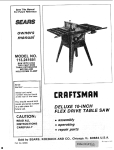
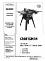
MODEL NO,
113.241680
SAW WITH LEGS
TWO TABLE EXTENSIONS
AND MOTOR
Serial
Number
Model
and serial
MRN
number may be found
at the rear of the base.
You should record both
model and serial number
in a safe place for
future use.
IO-INCH
FLEX DRIVE
TABLE SAW
CAUTION:
• assembly
READ ALL
INSTRUCTIONS
CAREFULLY
• operating
• repair
Sold by SEARS,
Part No. 62868
ROEBUCK
parts
AND CO., Chicago,
IL. 60684
U.S.A.
Printed
in U,S.A
FULL ONE YEAR WARRANTY
ON CRAFTSMAN
TABLE SAW
If within one year from the date of Purchase
this Craftsman Table Saw fails due to a defect in
material or workmansnip, _ears will repair'it,
free of charge.
WARRANTY SERVICE IS AVAILABLE
BY SIMPLY CONTACTING
THE NEAREST SEARS
SERVICE CENTER/DEPARTMENT
THROUGHOUT
THE UNITED STATES.
This warranty applies only while this product
is in use in the United States,
This warranty gives you specific legal
from state to state.
SEARS, ROEBUCK
GENERAL
SAFETY
AND
CO.;
rights,
Dept.
and you may also have other rights which vary
698/731A.
iNSTRUCTiONS
1. KNOW YOUR POWER TOOL
Read and understand the owner's manual
and
labels affixed to the tool. Learn its application
and limitations as well as the specific potential
hazards peculiar to this tool.
2. GROUND ALL TOOLS
This tool is equipped with an approved
3conductor cord and a 3-prong grounding
type
plug to fit the proper grounding type receptacle
The green conductor
n the cord
is the
g rounding wire. Never connectthe green wire to
a live terminal.
3. KEEP GUARDS IN PLACE
in working order, and in proper adjustment
alignment.
4. REMOVE ADJUSTING
KEYS
AND WRENCHES
Form habit of checking to see that keys
adjusting wrenches are removed from
before turning it on.
S. KEEP WORK AREA CLEAN
Safety goggles (must comply
with
FOR POWER
TOOLS
Z87.1) at all times. Everyday
eyeglasses
only
have impact
resistant
lenses, they are NOT
safety gtasses, Also, use face or dust mask if
cutting
operation
is dusty, and ear protectors
(plugs or muffs)
during
extended
periods
of
operation.
13. SECURE WORK
Use clamps
or a v_se to hold work when
practical. It's safer than using your hand, frees
both hands to operate tool.
DON'T OVERREACH
Keep proper footing and balance
MAINTAIN
and
TOOLS
WITH
at all times.
CARE
Keep tools sharp and clean for best and safest
performance.
Follow instructions for lubricating
and changing accessories.
16. DISCONNECT
TOOLS
before servicing;
when changing
such as blades, bits, cutters, etc.
and
tool
accessories
17. AVOID ACCIDENTAL
STARTING
Make sure switch is in "OFF" position before
plugging in
18. USE RECOMMENDED
ACCESSORIES
Consult the owner's manual for recommended
accessories.
Follow
the instructions
that
accompany
the accessories.
The
use
of
improper
accessories
may cause hazards.
19. NEVER STAND
ON TOOL
Serious injury could occur if the tool is tipped or
if the cutting
tool is accidentally
contacted.
Do not store materials
above or near the tool
such that it is necessary to stand on the tool to
Cluttered areas and benches invite accidents.
Floor must not be slippery due to wax
or
sawdust,
6. AVOID DANGEROUS
ENVIRONMENT
Don't use power tools in damp or wet locations
or expose them to rain. Keep work area well
lighted. Provide adequate surrounding
work
space.
7. KEEP CHILDREN AWAY
All visitors should be kept a safe distance from
work area.
Wear
Sears Tower, Chicago, IL 60684
ANSI
a complete stop.
2
AE)DJTIONAL SAFETY aNSTRUCTiONS
WARNING: FOR YOUR OWN SAFETY, DO NOT
OPERATE YOUR SAW UNTIL iT iS COMPLETELY
ASSEMBLED AND iNSTALLED ACCORDING TO
THE iNSTRUCTiONS
... AND UNTIL YOU HAVE
READ AND UNDERSTAND THE FOLLOWING.
1. GENERAL
SAFETY iNSTRUCTiONS
POWER TOOLS ... SEE PAGE 2
FOR
2. GETTING TO KNOW YOUR SAW... SEE PAGE
27.
3. BASIC SAW OPERATION ... SEE PAGE 30.
4. MAINTENANCE...
SEE PAGE 38.
5. STABlUTY OF SAW
If there is any tendency for the saw to tip over or
move during certain cutting operations such as
cutting extremely large heavy panels or long
heavy boards, the saw should be bolted down.
if you attach any kind of table extensions over
24" wide to either end of the saw. make sure you
either bolt the saw to the bench or floor as
appropriate, or support the outer end of the
extension
from the bench
or floor,
as
appropriate.
6. LOCATION
The saw should be positioned so neither the
operator nor a causal observer is forced to stand
in line with the saw blade.
FOR TABLE SAWS
operating immediately
until the particular
part is properly repaired or replaced.
B. Small loose pieces of wood or other objects
that contact the rear of the revolving blade
can be thrown back at the operator at
excessive speed. This can usually be avoided
by keeping the guard and spreader in place
for all thru-sawing
operations
(sawing
entirely thru the work) AND by removing all
loose pieces from the table with a long stick
of wood IMMEDIATELYafter
they are cut off.
O. Use extra caution when the guard assembly
is removed for resawing, dadoing, rabbeting,
or molding -- replace the guard as soon as
that operation is completed.
g. For rip or rip-type cuts, the following end of a
workpiece to which a push stick or push
board
is applied
must
be square
{perpendicular
to the fence) in order that
feed pressure applied to the workpiece by
the push stick or block does not cause the
workpiece to come away from the fence, and
possibly cause a kickback.
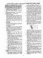
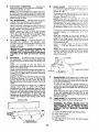
E. During rip and rip type cuts, the workpiece
must be held down on the table and against
the fence with a push stick, push block, or
featherboards.
A featherboard
is made of
solid tumber per sketch.
l=
7. KICKBACKS
A "KICKBACK"
occurs
during
a rip-type
operation when a part or all of the workpiece is
thrown back violently toward the operator.
Keep your face and body to one side of the
sawblade, out of line with a possible "Kickback."
Kickbacks -- and possible injury from them -can usually be avoided by:
A. Maintaining the rip fence parallel to the
sawblade.
B. Keeping the sawblade sharp. Replace or
sharpen antikickback pawls when points
become dull.
C. Keeping sawblade guard, spreader, and
antikickback
pawls in place and operating
properly. The spreader must be in alignment
with the sawblade and the pawls must stop a
kickback once it has started.
Check their action before ripping.
D. NOT ripping work that is twisted or warped
or does not have a straight edge to guide
along the rip fence.
E. NOT releasing work until you have pushed it
all the way past the sawblade.
F. Using a push stick for ripping widths of 2 to 6
in., and an auxiliary fence and push block for
ripping widths narrower than 2 in. (See
"Basic Saw Operation Using The Rip Fence"
section.)
G. NOT confining the cut-off piece when
ripping or cross-cutting.
H. When ripping apply the feed force to the
section of the vvorkpiece between the saw
blade and the rip fence.
8. PROTECTION:
EYES, HANDS, FACE, EARS,
BODY
A. If any part of your saw is malfunctioning, has
been damaged or broken . • • such as the
motor switch, or other operating control, a
safety device or the power cord..,
cease
F.
G.
H.
i.
J.
K.
L.
M.
24"
,_
5/16"
APART
KERFS
ABOUT
J_
NEVER turn the saw "ON" before clearing
the table of all tools, wood scraps, etc.,
except the workpiece and related feed or
support devices for the operation planned.
NEVER place your face or body in line with
the cutting tool.
NEVER place your fingers or hands in the
path of the sawblade or other cutting tool.
NEVER reach in back of the cutting tool with
either hand to hold down or support the
workpiece, remove wood scraps, or for any
other reason. Avoid awkward operations and
hand positions where a sudden slip could
cause fingers or hand to move into a
sawblade or other cutting tool.
DO NOT perform layout, assembly, or setup
work on the table while the cutting tool is
rotating.
DO
NOT
perform
any
operation
"FREEHAND"
-- always use either the rip
fence or the miter gauge to position and
guide the work.
NEVER use the rip fence when crosscutting
or the miter gauge when ripping. DO NOT
use the rip fence as a length stop.
Never hold onto or touch the "free end" of the
workpiece or a "free piece" that is cut off,
while power is "ON" and/or the sawblade is
rotating.
Shut "OFF" the saw and disconnect the
power cord when removing the table insert,
changing
.........
toot, removing or
replacing the blade guard,
or making
adjustments.
N. Provide
adequate support to the rear and
sides of the saw table for wider or long
work pieces.
O. Plastic and composition
(like hardboard)
materials may be cut on your saw. However,
since these are usually quite hard and
slippery, the antikickback
pawls may not
stop a kickback.
Therefore,
be especially
attentive
to
following
proper
set-up
and cutting
procedures for ripping. Do not stand, or
permit anyone else to stand, in line with a
potential kickback.
P. If you stall or jam the sawblade in the
workpiece, turn saw 'OFF", remove the
workpiece from the sawblade and check to
see if the sawblade is parallel to the miter
gauge grooves and if the spreader is in
proper alignment
with the sawblade. If
ripping at the time, check to see if the rip
fence is parallel with the sawblade. Readjust
as indicated.
Q. DO NOT remove small pieces of cut-off
material that may become trapped inside the
blade guard while the saw is running. This
could endanger your hands or cause a
kickback. Turn saw "OFF" and wait until
blade stops.
R. Use extra care when ripping wood that has a
twisted grain oris twisted or bowed -- it may
rock on the table and/or pinch the sawblade.
9. KNOW YOUR CUTTING TOOLS
A. Dull, gummy, or improperlysharpened or set
cutting tools can cause material to stick,jam,
when ripping, use the maximum diameter blade
for which the saw is designed, since under these
conditions the spreader is nearest the blade.
14. Adjust table inserts flush with the table top.
NEVER operate the saw unless the proper insert
is installed.
15. NEVER feed material into the cutting tool from
the rear of the saw. An accident and serious
injury could result.
17. NEVER use another person as a substitute for a
table extension, or as additional support for a
workpiece that is longer or wider than the basic
saw table, or to assist in feeding or supporting or
pulling the workpiece.
DO NOT pull the workpiece
through
the
sawblade - position your body at the nose (infeed) side of the guard: start and complete the
cut from the same side. This will require added
table support for iong or wide workpeices that
extend beyond the length or width of the saw
table.
18. THINK SAFETY.
Safety is a combination
sense and alertness at all
being used.
19. NOTE AND FOLLOW
TIONS THAT APPEAR
YOUR SAW.
I DAi_GER
READ
2.
USE
3.
KEEP
AND
SAWBLADE
HANDS
OUT
OF
FOR
PATH
4. USE
A "PUSH-STICK"
WHEN
1_ WEAR
SAFETY
GOGGLES.
USE
120
WARNING:
too and machine maintenance.
NEVER ATTEMPT TO FREE A STALLED
SAWBLADE WITHOUT
FIRST TURNING
THE SAW OFF.
THIS SAW.
11. Crosscutting operations are more conveniently
worked and with greater safety if an auxiliary
wood facing isattached tothe mitergauge using
the holes provided. However, the facing must
not nterfere with the proper functioning
of the
sawblade guard.
12.
rotates
SAFETY iNSTRUCON THE FRONT OF
I FOR YOUR OWN SAFETY:
UNDERSTAND
GUARD
of operator common
times when the saw is
OWNERS
MANUAL
"THRU-SAWING."
OF
SAWBLAOE,
BEFORE
6.
DO
NOT
7.
NEVER
OPERATING
PERFORM
REACH
MACHINE.
OPERATIONS
AROUND
OR
"FREEHAND."
OVER
SAWBLADE.
REQUIRED.
VOLT,
|5 AMP
BRANCH
S* KNOW
CIRCUIT
HOW
AND
TO AVOID
"KICKBACKS.'.'
USE
15 AMP,
TIME
DELAY
FUSE,
20. WARNING: DO NOT ALLOW FAMILIARITY
(GAINED FROM FREQUENT USE OF YOUR
SAW) TO BECOME
COMMONPLACE.
-
wrench to just "snug" it.
WEAR YOUR
The operation of any power tool can result in foreign
thrown i
which can result
y goggles
ge)
Ltion. Safety
retail or catalog
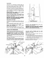
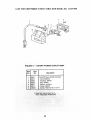
MOTOR
SPECJFICATmONS
AND
This saw is designed to use a 3450 RPM motor only.
Do not use any motor that runs faster than 3450
RPM It is wired for operation on 110-120 volts, 60
Hz., Alternating
current.
IT MUST NOT BE
CONVERTED TO OPERATE ON 230 VOLTS.
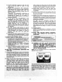
The Black and Red motor leads are connected to
quick connect tabs "A" and "B" on terminal board.
WARNING: Do not change any of these connections with current on.
BLACK
A
POWER LEAD
®
TI
GREEN
GROUND
SCREW
RED
POWER LEAD
CAUTION: Do not use blower or washing machine
motors or any motor with an automatic reset
overload protector as their use may be hazardous.
For replacement motor refer to parts list in this
manual.
CONNECTING
TO POWER SOURCE OUTLET
This saw must be grounded while in use to protect
the operator from electrical shock.
If power cord is worn or cut, or damaged in anyway,
have it replaced immediately.
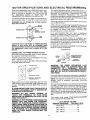
If your saw is for use on less than 150 volts it has a
plug that looks like below.
3-PRONG
PLUG
\
GROUNDING
3-PRONG
PRONG
GROUNDED
OUTLET
Plug power cord of fully assembled saw into 110120V properly grounded type outlet protected by a
15-amp. time delay or Circuit-Saver fuse or circuit
breaker.
IF YOUR ARE NOT SURE THAT YOUR OUTLET IS
PROPERLY GROUNDED, HAVE IT CHECKED BY
A QUALIFIED ELECTRICIAN.
WARNING:
DO NOT PERMIT
FINGERS
TO
TOUCH
THE TERMINALS
OF PLUG WHEN
INSTALLING OR REMOVING THE PLUG TO OR
FROM THE OUTLET.
WARNING: IF NOT PROPERLY GROUNDED THIS
POWER TOOL CAN INCUR THE POTENTIAL
HAZARD OF ELECTRICAL SHOCK PARTICULARLY WHEN USED IN DAMP LOCATIONS, IN
PROXIMITY TO PLUMBING, OR OUT OF DOORS.
IF AN ELECTRICAL SHOCK OCCURS THERE IS
THE POTENTIAL OF A SECONDARY HAZARD
SUCH AS YOUR HANDS CONTACTING
THE
SAWBLADE.
ELECTRmCAL
REQUIREMENTs
This saw is equipped with a 3-conductor cord and
grounding type plug which has a grounding Prong,
approved by Underwriters'
Laboratories
and th_
Canadian Standards
Association.
The ground
conductor has a green lug and is attached to the to(_
housing at one end and to the ground prong in the
attachment plug at the other end.
This plug requires a mating 3-conductor
type outlet as shown.
grounded
If the outlet you are planning to use for this saw is of
the two prong type DO NOT REMOVE OR ALTER
THE GROUNDING PRONG IN ANY MANNER. Use
an adapter as shown and always connect
th_
grounding lug to a known ground.
It is recommended
that you have a qualified
electrician replace the TWO prong outlet with a
properly grounded THREE prong outlet.
An adapter as shown below is available
for
connecting plugs to 2-prong receptacles. The green
grounding lug extending from the adapter must be
connected to a permanent ground such as to a
properly grounded outlet box.
An adapter as illustrated is available for connecting
plugs to 2-prong receptacles.
GROUNDING
LUG
/
!
s,,
ADAPTER
WARNING:
THE GREEN
GROUNDING
LUG
EXTENDING FROM THE ADAPTER MUST BE
CONNECTED
TO A PERMANENT
GROUND
SUCH AS TO A PROPERLY GROUNDED OUTLET
BOX. NOT ALL OUTLET BOXES ARE PROPERLY
GROUNDED.
If you are not sure that your outlet box is properly"
grounded, have it checked by a qualified electrician.
NOTE: The adapter illustrated is for use only if you
already
have a properly
grounded
2-prong
receptacle.
The use of any extension cord will cause some loss
of power. To keep this to a minimum and to prevent
ever-heating
and motor burn-out, use the table
below to determine the minimum wire size (A.W.G,)
extension cord. Use only 3 wire extension cord_
which have 3 prong grounding type plugs and 3pole receptacles which will accept the plug on the
saw.
The motor must rotate COUNTERCLOCKWISE
when viewed from the shaft end.
1 H.P. MOTOR 110-120V
Extension Cord Length
Wire Size A.W.G_:
Up to 50 Ft.................
50 to 100 Ft ................
t ........
/.......
UU
- tUU r .
.......
200 - 400 Ft.................
14
12
10
8
CONTENTS
WARRANTY
.................................
GENERAL SAFETY INSTRUCTION
2
• ,
Tilt Handwheel
...........................
Tilt Lock Handle ..........................
Rip Fence .................................
Miter Gauge ..............................
Blade Guard ..............................
Table Insert ..............................
Removing and installing Sawblade .........
Exacti-Cut ................................
BASIC SAW OPERATION USING THE MITER
GAUGE
Work Helpers .............................
Using the Miter Gauge ....................
Crosscutting
..............................
Repetitive Cutting .........................
Miter Cutting
.............................
Bevel Crosscutting
........................
Compound Miter Cutting ..................
BASIC SAW OPERATION USING THE RIP
FENCE ..................................
Ripping
..................................
Bevel Ripping .............................
Ploughing and Molding ...................
Resawing .................................
Cutting Panels ............................
Rabbeting
................................
Dadoing ..................................
Using Featherboards ......................
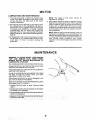
MOTOR ....................................
MAINTENANCE
............................
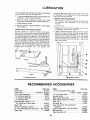
LUBRICATION
.............................
RECOMMENDED ACCESSORIES
...........
TROUBLE SHOOTING ......................
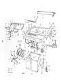
REPAIR PARTS .............................
2
Tools Needed ..............................
6
List of Loose Parts .........................
7
ASSEMBLY ...................................
8
Assembling Steel Legs .....................
8
Mounting Saw .............................
9
Installing Handwheels .....................
10
Checking Table Insert. ...............
.....
10
Heeling Adjustment of Parallelism of
Sawblade to Miter Gauge Groove . ........
11
Blade Tilt, or Squareness of Blade to Table
12
Tilt Mechanism
...........................
14
Mounting The Motor ......................
14
Mounting The Flexible Shaft ................
15
Attaching Table Extensions ................
18
Mounting Switch ..........................
19
Installing Rip Fence Guide Bars ..........
. 19
Aligning Rip Fence ........................
21
Adjusting Rip Scale Indicator ..............
23
Installing Blade Guard ....................
23
Aligning Spreader .........................
25
Adjusting Miter Gauge ....................
25
Plugging in the Motor .....................
26
GETTING TO KNOW YOUR SAW ............
27
On-Off Switch ............................
27
Elevation Handwheel ......................
28
UNPACKING
AND CHECKING
28
28
28
28
28
28
29
29
30
30
31
31
32
32
33
33
33
33
35
36
36
36
37
37
38
38
39
39
40
42
CONTENTS
TOOLS NEEDED
COMBINATION
.
..
Meolum
.
SQUARE MUST BE TRUE.
, .
_crewarzver
3/4"
_
Small Screwdriver
DRAW
BOARD
-
LIGHT
ALONG
LINE
THIS
ON
THICK.
THIS
EDGE
MUST
STRAIGHT
BE PERFECTLY
EDGE STRAIGHT.
OF BOARD
EDGE
_?-.
//_
t \I
#2 Ph|llips Screwdriver
_1
Pliers
J
l
SHOULD
Combination
Square
one carton and INCLUDES Two T;
Steel Legs, and Motor.
are installed correctly.
inches
7/16 in.
BE
NO
GAP
OR
OVERLAP
HEREovERWHENIN
DOTTEDSQUAREposITION.IS
FLIPPED
the protective oil that is applied to the tab e
edges of the table. Use any ordinary
_ld type grease and spot remover.
'N: TO a_oid fire or health hazard never use
, napUta or similar highly volatile solvents.
coat of automobile wax to the table.
parts thoroughly with a clean, dry cloth.
IG: FOR YouR OWN SAFETY, NEVER
CT PLUG TO POWER SOURCE OUTLET
i.LL ASSEMBLY STEPS ARE COMPLETE,
)U HAVE READ AND UNDERSTAND THE
' AND OPERATIONAL iNSTRUCTiONS.
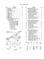
LISTOFLOOSEPARTS
Part Hame
item
A
B
C
D
E
F
G
H
J
K
L
M
N
O
P
Qty.
Blade Guard and Spreader .............
Rip Fence ............................
Owners Manual ......................
Miter Gauge .........................
Rod, Separation (Fence) ...............
Leg .................................
Stiffener, End ........................
Stiffener, Side ........................
Handwheel ..........................
Extension, 10 x 27 ....................
Motor ...............................
Motor Mount .........................
Shaft, Flexible .......................
Rip Fence Guide Bar with Rip Scale ....
Rip Fence Guide Bar, Rear .............
Loose Parts Bag ......................
(Containing the Following Items):
Loose Parts Bag No. 62752 .......
Loose Parts Bag No. 62745 .......
Loose Parts Bag No. 62890 .......
Loose Parts Bag No. 62889 .......
Loose Parts Bag No. 62891 .......
Q Outlet. On/Off ................
R Key, Switch .................
S Wrench. Arbor ...............
T Bracket. Shaft ...............
U Support, Spreader ...........
!
1
1
1
1
4
2
2
2
2
1
1
1
i
1
1
1
2
1
1
1
1
t
1
2
1
Item
Part Name
Qty.
C
D
D
E
E
F
G
G
Loose Parts Bag No. 62745 ............
(Containing the Following Items):
Bracket, Corner Support ..........
Bracket, Corner Stiffener ..........
Loose Parts Bag No. 62837 ............
(Containing the Following Items):
Screw, Truss Hd. 1/4-20 x 1 .......
Lockwasher, External 1/4 .........
Lockwasher, External 5/!6 ........
Nut, Hex 1/4-20 ...................
Nut, Hex 5/16-18 .................
Screw, Hex Hd. 5/16-18 x 1-1/4 ....
Washer, 11/32 x 11/16 x 1/16 .....
Washer, 17/64 x 3/4 x 1/16 .......
C
D
D
E
E
E
F
G
H
Loose Parts Bag No. 62752 for Legs ....
(Containing the Following Items):
Screw, Truss Hd. 1/4-20 x 5/8 .....
Lockwasher, External 1/4 .........
Lockwasher, External 5/16 ........
Nut, Hex 1/2-13 ..................
Nut, Hex 1/4-20 ..................
Nut, Hex 5/16-18 .................
Screw Hex 5/16-18 x 1-1/4 ........
Washer. 11/32 x 11/16 x 1/16 .....
Foot. Leveling ....................
A
B
2
2
2
1
8
8
4
8
4
4
4
2
1
24
24
4
8
24
4
4
8
4
Loose Parts Bag No. 62890 ...........
(Containing the Following Items):
D
Lockwasher, External #10 .........
D
Lockwasher. External 1/4 .........
D
Lockwasher. External 5/18 ........
E
Nut, Hex 1/4-20 ..................
E
Nut, Hex 5/16-18 .................
F
Screw, Hex Hd. 1/4-20 x 1 .........
G
Washer, 21/64 x 5/8 x 1/16 .......
G
Washer. 17/64 x 3/4 x 1/!6
.......
G
Washer. 21/64 x 47164 x t/16
.....
J
Screw, Pan Hd. Type "T" 10-32 x 3/8
K
Bolt, Carriage 1/4-20 x 3/4 ........
K
Bolt. Carriage 5/16-18 x 3/4 ........
1
3
6
4
6
8
2
2
2
4
3
4
4
NA
B
C
D
E
F
_
s
u
G
J
H
K
Item
A
B
C
D
D
D
E
E
E
F
G
H
J
Part Name
Loose Parts Bag No. 62889 ...........
(Containing the Following Items):
Nut, Weld ......................
Clamp, Spreader ................
Bracket, Spreader ...............
Lockwasher, External t/4 ........
Lockwasher, External #10 ........
Lockwasher, External 5/t6 .......
Wrench, Hex "L" 3/32 .......
Wrench, Hex " L" 1/8 ............
Wrench, Hex "L" 5/32
..........
Tie Wire ........................
Spacer, Fence Guide Bar .........
Nut, Self-Threading ..............
Connector, Motor ...............
Part Mame
item
Qty.
1
1
1
1
4
2
5
1
1
1
2
2
2
1
Loose Parts Bag No. 62891 ...........
(Containing the Following Items):
Bolt, Carriage 1/4-20 x 3/4 ........
Screw, Soc. Set 1/4-20 x 1 ........
Washer, 17/64 x 5/8 x 1/32 .......
Nut, Hex 1/4-20 ..................
Nut, Wing 1/4-20 .................
Screw, Hex Hd. 5/16-18 x 1-3/4 ....
Screw, Hex Hd. 5/16-18 x 3/4 ......
Screw, Hex Hd. 5/16-18 x 1 ........
Screw, Pan Hd. 10-32 x 3/4 ........
Key, Sq. 3/16 ....................
A
B
C
D
E
F
F
F
G
H
A
A
B
Qty.
1
B
C
D
4
2
4
4
2
2
1
2
2
1
E
C
D
o
F
H
G
F
J
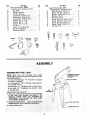
ASSEMBLY
ASSEMBLING
STEEL
LEGS
J\
ASSEMBLE
SCREWS
THROUGH
HOLES
MARKED
"X"
NOTE: Steel Legs are furnished
with Model
113.241680. From among the loose parts, find the
following Hardware:
24 Truss Head Screws, 1/4 - 20 x 5/8 in. long (top
of screw is rounded)
24 Lockwashers, 1/4 in. External Type (approx.
dia. of hole 1/4 in.)
24 Hex Nuts, 1/4- 20 (approx. dia. of hole 1/4 in.)
8 Hex Nuts, 1/2 -13 (approx. dia of hole 1/2 in.)
4 Leveling feet.
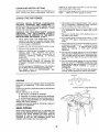
Assemble the legs as shown ...
1. Insert the Truss Head Screws through
STIFFENERS
SIDE
END
STIFFENER
STIFFENER
\
\
\
MARKED "X".
IN. HEX
3. Install leveling
feet.
$
NUTS
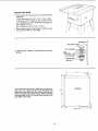
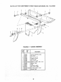
MOUNTING
SAW
1. From among the loose parts, find the following
hardware:
4 Hex Head Screws, 5/16 - 18 x 1-1/4 in. long.
4 Hex Nuts, 5/16- 18 (approx. dia. of hole 5/16 in.)
4 Lockwashers, 5/16 in. External Type (approx.
dia. of hole, 5/16 in.)
8 Flat Washers, (dia. of hole 11/32 in.)
2. Place saw on legs so that holes in bottom of saw
line up with holes in top of legs.
SAW
HEX
FLAT
3. Install screws, washers, Iockwashers and nuts as
shown.
HEAD
SCREW
BASE
_l
I
WASHER----_
!
END
FLAT
_
WASHER
""
__
LOCKWASHER/_]:=
HEX NUT
STIFFENER-_|
"""/_
11-1/4
®
®
]
OPENING
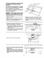
If you mount the saw on any other bench, make sure
that there is an opening in the top of the bench the
same size as the opening in the bottom of the saw so
that the sawdust can drop through. Recommended
working height is 33 to 37 inches from the top of the
saw table to the floor.
16-3/4"
15-1/;
I
1/2"
r
--
-@-
7/16"
FRONTOFSAW
9
DIA.
HOLES
.....
iMPORTANT
m Read
Before
Proceeding
Blade cannot be more than 2 inches above the table
top when tilting the sawblade to make bevel cuts or
adjustments. Lower blade to 2 inches or closer to
the table top to tilt the saw. Failure to do this may
result in damage to your saw.
INSTALLING
LOCKWASHER
/
10-32 x 3/4 IN.
PHILLIPS
HANDWHEELS
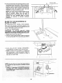
CHECKING
TABLE
HEAD SCREW
ELEVATION
HANDWHEEL
Line up FLAT SPOTS on shaft and handwheel, push
handwheel onto shaft. Install screw and Iockwasher
to lock handwheels on shaft.
TILT HANDWHEEL
/
\,
iNSERT
1. Insert should be even with table top. Check as
shown, Loosen flat head screw that holds insert
and adjust the four set screws as necessary.
Tighten flat head screw. Do not tighten screw to
the point where it deflects the insert.
\
TABLE
3/32
SETSCREW
2. To remove insert.
A. Loosen Phillips Flat Head Screw.
B. Lift insert from front end, and pull toward front
of saw.
INSERT_
IN
WRENCH
_-..._1
3. To replace insert.
Place insert into insert opening in table and push
toward rear of saw to engage spring clip and until
keyslot in insert will drop over screw. Tighten
screw_
.
.....
Do not tighten screw to the point where it will
deflect the insert.
_-_.
F/
10
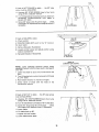
HEELING ADJUSTMENT
or PARALLELISM
OF SAWBLADE TO MITER GAUGE
GROOVE
MARK'X"ON
TOOTH
While cutting, the material must move in a straight
line PARALLEL to the SAWBLADE . . . therefore
both the miter gauge GROOVE and the RIP FENCE
must be PARALLEL to the SAWBLADE.
If the sawblade IS NOT parallel to the miter gauge
groove, the blade will bind at one end of the cut.
(This is known as "HEELING").
//
To check for parallelism:
WARNING
-TO AVOID
INJURY
FROM
ACCIDENTAL START, TURN SWITCH "OFF" AND
REMOVE PLUG FROM POWER SOURCE OUTLET.
//
1. Raise blade all the way up by turning elevation
handwheel clockwise.
2. Mark an "x" on one of the teeth which is SET
(bent) to the LEFT.
3. Place the head of a combination square in the
GROOVE...
adjust blade of square so that it just
touches the tip of the MARKED tooth.
4. Move square to REAR, rotate blade to see if
MARKED tooth again touches blade of square.
5. If tooth touches square at FRONT and REAR...
sawblade
is PARALLEL to MITER GAUGE
GROOVE.
6. If tooth does not touch the same amount .. the
mechanism
underneath must be adjusted to
make the blade PARALLEL to GROOVE.
o
A. Rear support
bearing
must be moved
TOWARD the combination square if there is a
space between marked tooth and end of
square in step 4.
B. Rear support bearing must be moved AWAY
from the square if marked tooth pushes square
out of position in the groove.
I
REAR SUPPORT
BEARING
o
t_J
I
tiLT
CLAMP
ILT LOCK
HANDLE
7. Make sure tilt clamp screw is tightened.
/
!
/-
-'l.J
8. Loosen both screws that hold the rear support
bearing and both screws that-hold
the front
support bearing.
NOTE: Rear screws can be reached through back
of saw. Use a 9/16-in. wrench. To reach front
support bearing screws insert open end wrench
through opening in front of base bythe tilt clamp
screw.
"%'-.L
O
FRONT
SUPPORT
BEARING
11
\
\
r--SCREW
WOOD
.9. Using a wood block and hammerasshown,
move
rear support bearing to right or left as required to
realign the blade. If necessary, shift front support
bearing in similar manner; but do NOT move front
support bearing unless necessary. Recheck the
alignment
with the square, then securely
retighten all support bearing screws.
NOTE: Be certain that the Widest blade you use
does not contact
blade insert after moving
support
bearing.
Check
this at both 0°
(perpendicular
to the table) and 45 ° bevel by
rotating
the fully elevated blade by hand.
Readjust as required to maintain
sufficient
clearance.
BLADE
BLADE
TILT, OR SQUARENESS
TO TABLE
O
_1
\\_
I
OF
90 ° (SQUARE) and 45 ° (BEVEL) STOP SCREWS.
When the bevel pointer is pointing directly to the
"O" mark on the bevel scale, the sawlolade should
make a SQUARE cut 90 ° to the table.
To check for SQUARENESS:
WARNING:
TO AVOID
INJURY
FROM
ACCIDENTAL START, TURN SWITCH "OFF" AND
REMOVE PLUG FROM POWER SOURCE OUTLET.
1. Blade should be all the way UP.
2. Place the square against blade. Make sure square
is not touching the TIP of one of the saw TEETH.
3. Turn
the tilt-lock
handle
(COUNTER-CLOCKWISE) to loosen the tilt clamp screw,.
4. NOTE: Handle is spring loaded for engagement
with screw head -- must be pushed inward for
disengagement whenever necessary to obtain a
new grip on screw head.
12
•
•
BLOCK
If blade is NOT SQUARE to table..,
screw must be ADJUSTED.
7
the 90 ° stop
A. Unscrew 90° STOP SCREW three to four turns
using 3/16 in. setscrew wrench.
B. Turn tilt handwheel clockwiseoneturn,
then turn
handwheel
counterclockwise
until blade is
square with table.
C. Screw 90 ° stop screw IN until it stops..,
check
once again for squareness and readjust screw, if
necessary.
If blade is SQUARE to table:
A. Check pointer
JF POINTER DOES NOT point to the "O" mark on
the bevel scale:
A. Remove Elevation Handwheel.
B. Loosen pointer screw and adjust pointer
medium screwdriver.
C. Reinstall Elevation Handwheel.
_POINTEk-_/ ADJUSTING
using
/
/
/
/
S%REW
/
POINTER
AT
"0" POSITION
HEAD
COMBINATION
OF
SQUARE
NOTE:
Lower sawblade
elevation
before
tilting
sawblade.
Failure to do this may result in damage to
your saw.
1. Lower the blade to about two inches above the
table.
2. Turn tilt handwheet
to a 45 ° bevel.
3. Raise
blade
counterclockwiseto
elevation
to maximum
4. Check
bevel of blade
combination
square.
with
If blade is NOT 45 ° to table..,
must be ADJUSTED.
the
until blade
height.
head
of
the
the 45 ° stop screw
A Unscrew
45 ° STOP SCREWthree
using 3/16 in. setscrew wrench.
B. Turn tilt handwheel
tilt blade
to four
turns
/
!
is 45 ° to the table.
C. Screw 45 ° stop screw IN until it stops..,
check
once again and readjust screw, if necessary.
5. Lower blade.
6. Tilt
blade
back
7. Tighten
tilt
8. Lower
blade
to 90 ° ,
lock handle.
below
STOP
table.
13
45 °
SCREW
_)
/
TILT
MECHANISM
Lower blade to 2 inches or closer to
before tilting blade. Failure to do this
damage to your saw.
the
may
TILT
table top
result in
HANDWHEEL
The handwheel should turn freely without
binding.
The turning action can be adjusted by tightening
or
loosening the screws in the bearing retainer.
NOTE: Tilt Handwheel must be removed
to adjust.
When adjusting the screws in the bearing
retainer
using a screwdriver, hold the nut inside
using a 3/8
in. wrench.
ADJUST
THESE
TWO
SCREWS
i
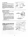
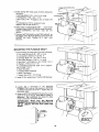
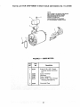
MOUNTING
THE MOTOR
NOTE: Motor is included with Model
This motor is non-reversible.
113.241680.
1 CHECK MOTOR ROTATION
A. The motor
must
rotate
COUNTER-CLOCKWISE when viewed from the shaftend.
B. MAKE SURE "KEY" IS REMOVED
FROM
SHAFT.
C. Place the motor on your workbench
floor.
5/8 iNCH
DIAMETER
Si-{AF_
__
or on the
D. Plug the cord into a properly grounded
outlet
(See "Motor Specifications
and
Electrical
Requirements" Section.) Notice
the rotation
of the
shaft.
If it is
ROt
turning
COUNTERCLOCKWISE,
do
not
continue
assembly. Contact your nearest Sears Store or
Service Center,
_"
COUNTER-CLOCKWISE
ROTATION
E. Remove plug from outlet.
WARNING:
TO AVOID
INJURY
FROM
ACCIDENTAL START, MAKE SURE
MOTOR IS
NOT PLUGGED INTO SWITCH OR ANY OTHER
ELECTRICAL OUTLET.
CARRIAGE
BOLT
1/4-20 x 3/4 IN.
2. From among the loose parts find the following:
1 Motor Mount
2 Carriage Bolts 1/4-20 x 3/4 in. long
2 Hex Nuts 1/4-20 (aprox. dia. of hole 1/4 in,)
2 Lockwashers External Type 1/4in.
(approx. dia.
of hole 1/4 in.}
3. Insert carriage bolts through square holes in rear
panel of table saw and through square
holes in
motor mount. Install Iockwashers
and hex nuts.
MOTOR
MOUNT
LOCKWASHER
HEXNUT
1/4-20
/
14
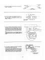
KEY
THESE
TWO
EDGES
EVEN
5. From among the loose parts, find the following
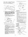
hardware:
4 Carriage Bolts, 5/16 - 18 x 3/4 in. long
4 Flatwashers 17/64 x 3/4 x 1/16
4 Hex. Nuts, 5/16 - 18 (approx. dia. of hole 5/16
in.)
4 Lockwashers, 5/16 in. External Type
(approx. dia. of hole 5/!6 in.)
++
IL.
1
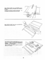
6. Place motor on MOTOR MOUNT...
insert bolts
through holes in MOUNT then through the motor.
Install Iockwashers,
and hex. nuts. Do not
tighten.
7. Position MOTOR BASE on MOTOR MOUNT so
the edges of the MOTOR BASE and the MOTOR
MOUNT are even. Tighten all 4 Hex. nuts
securely.
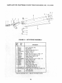
MOUNTING
THE FLEXIBLE
SHAFT
1. From among the loose parts find the following:
3 Pan Head Screws 8-32 x 3/8 in, long
3 Lockwashers External Type No, 8
2 Carriage Bolts 1/4 - 20 x 3/4 in+ long
2 Hex Head Screws 1/4-20 x 1 in. long
4 Hex Nuts 1/4-20 (approx. aia. of hole 1/4 in.)
2 Washers 17/64 x 3/4 x 1/16
4 Lockwashers External Type 1/4 in, (approx.
dia. of hole 1/4 in.)
2 Shaft Brackets
1 Flexible Shaft Assembly
1 Motor Connector
1 Square Key 3/16 x 15/16 long
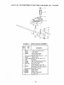
2. Install 3/16 in. square key in motorshaft keyway.
3/16 IN. SQUARE
KEY
3. Loosen the 2 setscrews
in the MOTOR
CONNECTOR. Line up the keyway in MOTOR
CONNECTOR with the 3/16 in. square key on
the motor shaft.
4. Slide the MOTOR CONNECTOR ontothe motor
shaft as far as it wilt go. SECURELY tighten 2
setscrews. Test setscrews by trying to slide
motor connector off motor shaft.
IMPORTANT:
Make sure the MOTOR
CONNECTOR is pushed on the shaft as far as It
will go. (Approx. 3/8 inch from motor end
shield.)
LOOSEN
_
3/8 INCH
___
_5
SETSCREWS _
/i+
SAW
MOTOR
END
_-_
_--
---_
ARBOR
ENO
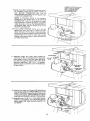
5. Removethe plasticcoversfromthe endsofthe
SHAFTHOUSING.
6. Push the saw arbor end of the flexible
shaft out
of
the
SHAFT
HOUSING
until
it
is
approximately
1 inch above
the end of the
SMALL FERRULE.
PULL FLEXIBLE
SHAFT OUT 1"
SAW
'J
ARBOR
END
L_.J
o
7. Insert the flexible
shaft assembly
through
the
opening in the side of the saw base. Line up the
SQUARE END of the FLEXIBLE SHAFT with the
square hole in the arbor shaft, holding
square
end of flexible shaft insert the FLEXIBLE
SHAFT
into the square hole in the arbor as far as it will
go.
iMPORTANT:
Make sure the FLEXIBLE
SHAFT is
inserted as far as it will go. Approximately
3/4
inch.
lING
8. Insert SMALL
into the arbor
Line
up SHAFT
FERRULE
on SHAFT
shaft bearing hole.
RETAINER
with
HOLE
HOUSING
holes
RETAINER
in arbor
""
LOCKWASHER
PAN HEAD
SCREW
10-32 x 318 IN.
16
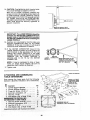
CAREFULLY
ROTATE
BLADE
HAND
TO LINE
UP SQUARE
END
OF FLEXIBLE
SHAFT
WITH SQUARE HOLE
MOTOR CQNNECTOR
9. Bend the SHAFT HOUSING
toward the motor
as illustrated.
Insert end of LARGE FERRULE
over
MOTOR
CONNECTOR
and
line
up
SQUARE
END of flexible shaft with square hole
in MOTOR CONNECTOR.
BY
IN
\
NOTE:
If FLEXIBLE
SHAFT
is not properly
positioned
in the square hole of the MOTOR
CONNECTOR
it will not be possible to make
this connection.
It may be necessary to carefully
rotate the blade to line up the SQUARE
END of
the flexible
shaft with the square hole in the
MOTOR
CONNECTOR.
10. Push LARGE
FERRULE
as far as it will go
against the motor end cap. If it does not enter
motor end cap to ferrule bead, rotate saw blade
while pushing ferrule toward motor to permit the
square ends of the core to enter their square
mating holes deep enough to ailow ferrule to be
correctly
positioned.
/
1/4-20 X 3/4 IN,,"<"_
/
•ocKwAS. .\1 II ,.....
11. Assemble
upper
and lower shaft bracket
by
inserting
1/4-20 x 3/4 carriage bolts in upper and
lower square holes on the saw base rear panel
and then through
the slotted hole in the shaft
brackets,
Assemble
17/64 x 3/4 x 1/16 washer,
External Type Lockwasher,
and 1/4-20 Hex Nut.
Finger tighten.
12. Position the upper and lower shaft brackets so
they wrap around the LARGE FERRULE on the
SHAFT HOUSING. Bottom bracket should just
contact and support LARGE FERRULE. Tighten
nuts that hold the shaft brackets to the saw base.
13. Assemble two 1/4-20 x 1 in. Hex Head Screws,
External Lockwashers, and 1/4-20 Hex Nuts to
clamp upper and lower brackets together, Do
not tighten.
r
•
BRACKET
I
|
14.CAUTION:Overtighteningshaft bracketbolts
maycausedamageto bracketor ferrule.
With end of LARGEFERRULEinsertedinto
recessin motor end cap tighten 2 Hex Head nuts
\
on shaft brackets. LARGE FERRULE must be
pushed against the motor end cap as faras it will
go. Tighten nuts but do not OVERTIGHTEN.
The shaft brackets hold the LARGE FERRULE in
place. Nuts should be securely tightened to
prevent movement.
I
BEAD ON FERRULE MUST
CONTACT
MOTOR END CAP
iMPORTANT: The LARGE FERRULE should be
centered over the MOTOR CONNECTOR (now
located inside of LARGE FERRULE), to prevent
the MOTOR CONNECTOR from contacting the
LARGE FERRULE.
15. Carefully turn saw blade by hand to make sure
MOTOR CONNECTOR
does not hit LARGE
FERRULE. If they are in contact, it will cause a
noise and cause resistance to rotation.
16. If the MOTOR CONNECTOR
does hit the
LARGE FERRULE loosen the nuts holding the
shaft brackets to the saw base, and the nuts
holding the LARGE FERRULE in the shaft
brackets. Adjust the brackets and the LARGE
FERRULE
until the LARGE
FERRULE
is
centered
and is not hit by the MOTOR
CONNECTOR.
/
,/
LARGE
FERRULE
MOTOR
CONNECTOR
MOVE
BRACKETS
UP OR
DOWN SO THAT MOTOR
CONNECTOR
INSIDE
NOT HIT FERRULE.
NOTE: It may be necessary to raise or lower
motor on motor mount slightly. Be sure to
reposition shaft brackets as required.
DOES
17. Tighten nuts.
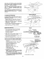
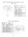
TABLE
EXTENSION
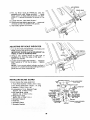
ATTACHING
AND ASSEMBLING
TABLE EXTENSIONS
From among the loose parts find the following
hardware: (Quantity indicated is for 2 extensions)
Ref.
No.
1
2
3
4
DescflpUon
Qty'.
Corner Support Bracket ............
Corner Stiffener Bracket ............
Truss Hd. Screw, 1/4-20 x 1 ........
External Lockwasher, 114 ...........
HARDWARE
MOUNT
TO TABLE
EXTENSION
USING
3AME ATTACHING
P'ARTS AS ON
OPPOSITE
SIDE.
SAW
4
4
16
16
1/
FOR i
8
9 Hex Nut, 5/16-18
10 Flat Washer
TABLE
/
8
9 _
E)E VIEW OF
BLED TABLE EXTENSION
, ...
18
Insert four (4) 5/16-18 x 1-1/4 in. long screws
through holes in each EXTENSION then through
table. Install flat washer, Iockwashers, and nuts on
the screws...
DO NOT TIGHTEN.
Align front edge of extension with front edge of saw
table. Pull Extension
UPWARDS above table
surface . .. SLIGHTLY TIGHTEN SCREWS using
1/2 in. wrench.
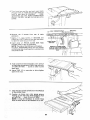
BLOCK
OF WOOD
\
Using small block of hardwood and hammer, tap
extension DOWNWARDS at front, center and rear,
until it is EVEN with table surface ... TIGHTEN
SC REWS.
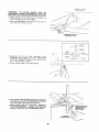
ALiGNiNG
CHECK
REAR
EXTENSIONS
AT FRONT
AND
OF EXTENSION
Lay REAR FENCE GUIDE BAR on table to act as a
straightedge, If outer edge of extension is higher or
lower than table surface:
1. Slightly loosen nut holding the corner support
bracket to extension using 7/16 in. wrench.
2. Move end of extension up or down until outer
edge is even with table surface..,
check with
GUIDE BAR...
tighten nuts.
3. Recheck INNER edge of extension to make sure it
has not moved..,
readjust, if necessary.
4. Adjust right extension
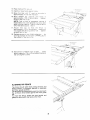
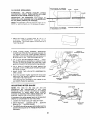
MOUNTING
in same manner.
SWITCH
J AM NUT
5/16-18
1. From among loose parts find the following:
2 Hex Head Screws, 5/16-18 x 3/4 in. long
2 F[atwashers (dia. of hole 21/64 in.)
"_
,,,7 LOCKWASHER
@-_
\
2 External Lockwashers
2 Hex Nuts. 5/16-18
,8TH HOLE
/
__
........
2. Insert two 3/4 inch screws through two flat
washers then through holes in switch.
3. Insert screws through holes eight and ten in front
fence guide bar as illustrated.
4. Install two Iockwashers and nuts. Tighten nuts.
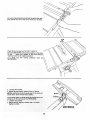
0NSTALLmNG RiP FENCE
"_
GUIDE
---_:F
\---_-_ _
1OTH HOLE
\ _
FRONT
FENCE
GUIDE
BAR
(UPSIDE
DOWN)
%%"---
WASHER
HEX HEAD
SCREW
5/16-18
x 5/8 IN.
BARS
LEFT
1. From among the loose parts find the following
hardware:
2 Hex Head Screws, 5/16-18 x 1-3/4 in. long
2 Hex Head Screws, 5/16-18 x 1 in. long
4 External Lockwashers, 5/16 in.
(approx. dia. of hole 5/16 in.)
4 Hex Nuts, 5/16-18
(approx. dia. of hole 5/16 in.)
2 Spacers, 3/4 in. dia. x 1/2 in. long
2 Self-threading nuts
1 Fence Guide Bar Rod
TTH
"_:_
2. Lay guide bars on saw table.
NOTE: The various holes in the bar allows them
to be positioned on this saw and also makes
them adaptable to other models.
3. Insert a 1-3/4 inch long screw through the
THIRD hole IN THE FRONT BAR as illustrated
•.. Insert another 1-3/4 inch long screwthrough
the SEVENTH hole in bar.
HOLE
3RD HOLE
_J"
4. Place spacers on screws.
19
SIDE
OF
FRONT GUIDE BAR
(GUIDE
BAR IS TO BE
TURNED
END FOR END
AFTER SCREWS ARE
_
HEX_HEAD
5_Turn front bar end for end and insert bolts
througr_holesin m_ddleandon right sidesof
front of saw tabte as i!lustrated . . install
!ockwashers
and nuts DON'T SCREW
ON ALL THE WAY. just get them started
NUTS
on the
sCreWS.
@..._ SELF-THREADING
X
6. Remove
extension
the
3
screws
from
rear
of
NUT
4TH
OR
5TH
2ND HOLE
HOLE
table
7 Insert
1 m
_ong screws
m SECOND
and
FOURTH or FIFTH holes of rear bar and atiach
to table the same way as front bar
8 }nsert
ends
of FENCE
GUIDE
BAR ROD
through
holes in bars as itlustrated
NOTE: The ends of the ROD are not threaded.
the SELF THREADING
NUTS will cut threads
on the rod as they are screwed on. Just start nuts
onto ends of rod.
FENCE
BAR
GUIDE
ROD
REMOVE
3 SCREWS
FROM
REAR OF TABLE
EXTENSION
BEFORE
INSTALLING
GUIDE
BAR.
9. Hold rod with one hand and with a 1/2 in. wrench
or pliers start screwing
on ONE of the nuts only
ATURN
ORTWO
. . screw on other nut the
same way
t0, Using TWO 1/2 in. wrenches
both of the nuts.
or pliers
tighten
/
/
t 1. Slide the bars so that screws are in the MIDDLE
of the slotted holes.
12, Position rip fence over miter gauge groove,
holding up the rear end while engaging front
end with bar.,,
lower fence onto table.
NOTE: tt may be necessary to loosen fence
knob to allow fence to be installed on rip rail.
13, Raise blade
!4. Carefuiiy
a!! the way _p,
move fence
against
blade.
!5. Move front bar untit "0" mark on rip scale
approximately
in line with indicator.
16. Move
FRONT
bar upwards
approximately
1/32 in, above
screw at left end of bar,
until
table.,
is
fence
is
, tighten
NOTE;
Fold a piece of newspaper
making
8
thicknesses
and place between
rip fence and
table to act as a spacer• This will hold the fence
off of the table approx. 1/32 in
17. Adjust
rear
bar
so that
the
fence
is
approximateiy
1/32 in, above tab!e
make sure
it is square with fence guide bar rod..,
tighten
screw at end of bar.
t8. Replace screws in rear of table extension,.,
sure top surface
of extension
is PARALLEL
top surface of rear guide bar.
be
to
19, Move fence to RIGHT edge of table , , , make
sure it is approx, t/32 in, above table at front and
rear and tighten screws,
ALIGNING
RIP FENCE
The fence should
slide easily along the bars and
always remain in alignment
(parallel
to sawblade
and miter gauge grooves).
The alignment
is maintained
by a spring underneath
the rip fence which bears against the front guide
bar.
To move the fence, loosen the lock handle and
grasp the fence with one hand at the front,
21
-"
\
For very close adjustments, grasp the guide bar with
both hands and move the fence with your thumbs.
Place fence on saw but DO NOT LOCK IT.
Move the REAR END of the fence slightly to the right
or left . . . when you release it, the fence should \
"spring" back to its original position.
If it does not,
INCREASED.
the
spring
pressure
must
be \
1. Loosen the screws.
2. Move Spring slightly toward front of fence.
SPRING
tighten screws.
SLIDE
ADJUST
22
SPRING
TO
PRESSURE
HEX SCREWS
FENCE HEAD
3. The rip fence must be PARALLEL with the
sawblade and miter Gauge grooves .,, Move
fence until it is along side of groove. Do NOT
LOCK IT. it should be parallel to groove, If it is
not;
A. Loosen the two "Hex Head Screws."
B. Hold fence head tightly against bar.., move end
of fence so that it is parallel with groove.
C. Alternately tighten the screws.
ADJUSTING
RiP SCALE
iNDiCATOR
1. Turn ELEVATION HANDWHEEL clockwise until
blade is up as high as it will go.
IMPORTANT: BLADE must be SQUARE (90 ° ) to
TABLE, in order to ALIGN rip fence.
LOCK
HANDLE
2. Using a rule, position fence on right side of
sawblade 2 in. from the sides of the teeth . . .
tighten lock handle.
3. Loosen screw holding the indicator.., adjust so
that it points to ,2" on the rip scale..,
tighten
screw.
NOTE: If you cannot adjust indicator so that it
points to "2", loosen the screws holding the front
guide bar and move the guide bar.
INSTALLING
BLADE
GUARD
SPREADER
PLATE
1. From Among the loose parts find:
4 Truss Head Screws 1/4-20 x 3/4 in. long
2 Hex Socket Setscrews 1/4-20 x 1 in. long
4 Washers 17/64 x 5/8 x 1/32
6 Lockwashers 1/4 in. External Type
(approx. dia. of hole 1/4 in.)
2 Hex Head Nuts 1/4-20
(approx. dia. of hole 1/4 in.)
2 Wing Nuts 1/4-20
(aprox. dia. of hole 1/4 in.)
1 Spreader Support
1 Plate Nut
1 Spreader Clamp
1 Spreader Bracket
\
SUPPORT
_.._TRUSS
\ tl'
HEAD
SCREW
SpREAOE,
/ C,,,P
TRUSS"%%%"EW
_----_-_"
-_'_'--'_J\t
"
i_'_._
_.
LOCKWASHERF'_!;_
LT _" ,
FLA
/'
_
OCKWASHER
_17/S,
_
HEX NUT
23
IN,HOLE
BLADE
W_TH
S©UARE
TABLE
WARNIlNG:
TO
AVOID
iNJURY
DUE;
TO
ACCIDENTAL
START. TURN SWITCH "OFF" AND
REMOVE PLUG FROM POWER SOURCE O UTLET.
2, MAKE SURE THE BLADE IS ALL THE WAY UP
AND SQUARE WtTH THE TABLE
3 Posit_on SPREADER
SUPPORT
even w_h the cod of the rod.
4 Assemble
the Zt8 in
long
_ockwashers
and washers
to
SUPPORT
BRACKET
and s_ip
slot m tr_e spreader support,
5, Finger tighten ONLY THE HEX
on rod until
it Js
setscrews
nuts
the SPREADER
the nuts into the
NUTS,
6 Lay a piece of fiat straight wood and a square on
saw table and rotate the SPREADER
SUPPORT
unti_ the bracket is a_igned with square.
7, MAKE SURE END OF SUPPORT,
BRACKET
AND ROD ARE EVEN..,
using a 1/8 in_ setscrew
wrench, TIGHTEN
THE SET_CREWS
ONLY.
ENDS
OF
SUPPORT
AND
BRACKET
BE EVEN
WITH
END
OF ROD
/
TIGHTEN
SETSCREW
24
ONLY
TO
ALIGNING
SPACE
EQUAL
3 THICKNESSES
SPREADER
TO APPROX_
OF PAPER
WOOD
KERr
WARNING:
TO
AVOID
_NJURY
FROM
ACCIDENTAL
START,
TURN SWITCH
OFF AND
REMOVE PLUG FROM POWER OUTLET.
IMPORTANT:
The SPREADER
must always
PARALLEL to the sawblade and in the MIDDLE
the cut (KERr) made by the sawblade,
BLADE
/
be
of
NOTE: The spreader is thinner than the width of the
KERr by approximately
six thicknesses
of paper.
SPACE
EQUAL
3 THICKNESSES
TO
LOOKING
APPROX.
OF PAPER
DOWN
ON
SAW
1. Make two folds in a small piece (6 x 6 in.) of
ordinary
NEWSPAPER
making
three
thicknesses,
The folded paper will be used as a
"spacing
gauge".
2. Install
TRUSS
HEAD
SCREWS,
SPREADER
CLAMP and WING NUTS to spreader bracket. Do
not tighten wing nuts. Place spreader between
spreader
clamp and bracket. Move forward until
all three are in line. TIGHTEN
WING NUTS.
PIECE
STRAIGHT
ANTIKICKBACK
PAWLS
TIGHTLY
AGAINST
HOLD
WOOD
BLADE
3. Lift up both ANTIKICKBACK
PAWLS,.,
insert
one of the setscrew
wrenches
or a pencil in the
notches to hold the pawls out of the way. Hold
guard so it doesn't fall while positioning
spreader,
OF
WOOD
1
THREE
THICKNESS
OF PAPER
4. Lay a piece of straight
flat wood against
the
sawblade.
Insert folded paper between spreader
and strip of wood.
5. MAKE SURE THE HEX NUTS UNDERNEATH
ARE LOOSE.
HOLD
SPREADER
TIGHTLY
AGAINST
6. Hold the spreader
tightly
against the wood and
make sure the wood is against the saw blade.
TIGHTEN
THE HEX NUTS.
This will align the spreader
in the middle
cut (KERr)
made by sawblade.
ADJUSTING
MITER
WING
NUT
!
WOOD
SPREADER
BRACKET
SPREADER
CLAMP
of the
GAUGE
LOCK
NOTE: The slots for the stop pin and the
graduations
are manufactured
to very close
tolerances which provide accuracy for average
woodworking,
in some cases where extreme
accuracy is required, when making angle cuts, for
example, make a trial cut and then recheck it.
If necessary, the miter gauge head can be swiveled
slightly to compensate for any inaccuracy.
1. Loosen the "knob" and pull "stop pin" OUT.
2. Swivel the head..,
position it at "0"... push the
stop ;)in IN...
lock the handle,
KNOB
INDICATOR
BLOCK
3. The HEAD should be square with the Bar and the
pointer should point to 0. Readjust the pointer if
necessary.
25
4. if the head is not square with the bar, adjustments
are required,
A. Loosen the "knob" (1) and the "two screws"
(2),
B. Position the HEAD square with the BAR using
a combination square.
C. PUSH the STOP PiN into theslot in the head a t
"0"...
push the pin into the slot and twist it.
Lock the knob.
D. Recheck with the square. If the head is still not
square, loosen the screws (2) and readjust the
INDICATOR BLOCK,
E. With the head square with the bar and the pin
pushed into the slot adjust the pointer (3) to
point to "0".
F. The miter gauge head must rest on top of the
bar without being able to move up and down
. . yet it must swivel freely.
G. The swiveling movement of the head can be
adjusted
by tightening
or loosening
the
setscrew (4) . .. using the 1/8 in. setscrew
wrench.
NOTE: The setscrew is located inside of the
head. To reach it, swivel the head to 60
degrees and turn the miter gauge upside
down.
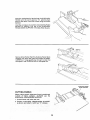
PLUGGING
1/8 IN. SETSCREW
WRENCH
IN MOTOR
1. From among the loose parts, find two wire ties.
2. Route motor cord along right side of cabinet and
snap ties in 1/4" hole in side of cabinet. Secure
two cords in wire ties.
3. Plug motor cord into outlet on side of switch box.
WiRE TIES
EXTENSION
REMOVED
PICTURE
CLARITY
FOR
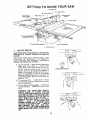
GETTING
TO KNOW
9
YOUR SAW
SAWBLADE
7'
8
TABLE,NSERT
M,TER
OAUGE 10EXACT-I-COT
1
LOCK
HANDLE
_
\
/
BLADE
/__
_.._._iit_.._
/
GUARD
> ANT'Z'C@CK
_
y
4"
TILT
LOCK
(UNDERNEATH
HANDLE
"_,._'_'
TABLE)
2
ELEVATION
v.w
ATTACHING
FACING
L_
_
3
HANDWHEEL
TILT
HANDWHEEL
\
]
1
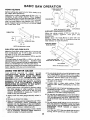
ON-OFF
ON-OFF
SWITCH
SWITCH
CAUTION:
Before turning switch on, make sure the
blade guard is correctly
installed
and operating
properly,
The On-Off
Switch
has a locking
feature.
THIS
FEATURE
IS
INTENDED
TO
PREVENT
UNAUTHORIZED
AND POSSIBLE
HAZARDOUS
USE BY CHILDREN
AND OTHERS,
A. TO turn saw ON..stand
to either side of the
blade never in line with it ...
insert finger
under switch lever and pull END of iever out,
Do not cycle the motor
switch on and off
rapidly,
as this may cause the sawblade
to
loosen. In the event this should ever occur
allow the sawblade
to come to a complete
stop and retighten the arbor nut normally, no_
excessively.
Never leave the saw while the
power is "ON".
B, TO turn saw OFF . . . PUSH lever in, Never
leave the saw until the cutting
tool has come
to a complete
stop.
KEY
(YELLOW PLASTIC)
¥
C. TO lock switch in OFF position..,
hold switch
IN with one hand ... REMOVE
key with other
hand.
WARNING:
FOR YOUR
OWN SAFETY,
LOWER BLADE OR OTHER
CUTTING
TOOL BELOW TABLE SURFACE. (IF BLADE
IS TILTED, RETURN iT TO VERTICAL (90 ° )
POSITION). ALWAYS LOCK THE SWITCH
"OFF". WHEN SAW IS NOT IN USE . . .
REMOVE KEY AND KEEP IT IN A SAFE
PLACE . . . ALSO . . . IN THE EVENT OF A
POWER FAILURE (ALL OF YOUR LIGHTS
GO OUT) TURN SWITCH OFF... LOCK IT
AND
REMOVE THE
KEY. THIS WILL
PREVENT THE SAW FROM STARTING UP
AGAIN WHEN THE POWER COMES BACK
ON.
kk
27
2
6
ELEVATION
HANDWHEEL
, . . elevates
or
lowers the blade. Turn clockwise
to elevate...
counterclockwise
to lower.
MITER GAUGE _ .nead is locked in position
for crosscutting
or mitering
by tightening
the
lock knob.
ALWAYS
LOCK
IT SECURELY
WHEN tN USE,
There are slots for the stop pin at the 45 degree
right and left positions forconveniently
setting
the Miter Gauge to cut miters.
NOTE: The slots for the stop pin and the
graduations
are manufactured
to very close
tolera nces which provide accuracy for average
woodworking.
In some cases where extreme
accuracy
is required, when making angle cuts,
for example, make a trial cut and then recheck
it.
If necessary, the miter gauge head can then be
swiveled
slightly
to compensate
and then
locked.
Slots are provided
in the miter gauge
for
attaching
an AUXILIARY
FACING to make it
easier to cut long pieces. Be positive facing
does not interfere with the proper operation
of
the sawblade
guard.
Select a suitable
piece of smooth
straight
wood ...
dril two holes and attach
it with
screws,
NOTE: When bevel crosscutting,
attach facing
so that it extends to the right of the miter gauge
and use the miter gauge in the groove to the
nght of the blade.
NOTE: Any time sawbiade
has been elevated
to 2-5/8 inches or higher above the table it will
be necessary
to lower the blade by turning
the
elevation
handwhee!
5 turns counterclockwise
before tilting to bevel,
3
TILT HANDWHEEL...
tilts the blade for bevel
cutting.
Turn clockwise
to tilt toward
left...
counterclockwise
to tilt toward vertical.
When the blade is tilted to the LEFT as far as it
will go, it should be at 45 ° to the table and the
bevel indicator should point 45° .
NOTE: There are LIMIT STOPS on the saw
which prevent the blade from tilting beyond
45° to the LEFT and 90 ° to the RIGHT. (See
"'Adjustments"
section
"'Blade
Tilt,
or
Squareness of Blade to Table").
4
TiLT LOCK HANDLE...
locks the blade in the
desired
tilt
position.
To
loosen,
turn
counterclockwise.
Push handle in and turn it to
another
position
if necessary
in order
to
tighten or loosen.
IMPORTANT:
Be sure handle is hanging in the
"DOWN"
position before tilting blade. If it is
pointing to the 1 o'clock position it may jam on
underside
of the table and bend the locking
boil
5
RIP FENCE...
is locked in place by tightening
the lock knob. To move the fence, loosen the
knob and grasp the fence with one hand atthe
front.
Holes
are
provided
in the rip fence
for
attaching
a wood facing when using the dado
head, or molding
head.
Select a piece of smooth straight wood approx.
3/4" thick, at least as long as the rip fence, and
at least 7-1/2" wide (high) to permit clamping
of featherboards.
_----
AUXILIARY
PiN
45 _ SLOT
FOR
If you are making
a rip type cut in material
thinner
than
3/16
in. while
the fence
is
positioned
over the depressed
area of table
extension,
the facing should be attached
to the
fence so that the bottom edge touches the top
surface
of the extension.
In this case, the
facing must be shorter than the fence. This will
prevent thin material from sliding under the rip
fence.
o
KNOB
/
STOP
Attach it to the fence with three Round Head
#10 Wood Screws 2 in. long. To remove
the
facing,
loosen
the screws,
slide the facing
forward and pull the screws through the round
holes.
WOOD
LOCK
FACING
STOP
FACING
\'_
PIN
7
BLADEGUARD must always be in place and
working properly for all thru-sawing cuts. That
is, all cuts whereby the blade cuts completely
through the workpiece.
To remove the guard for special operations,
loosen the wing nuts and slide the guard off of
the rod. DO NOT DISTURB THE SETTING OF
THE ROD.
When replacing the guard, make sure the PIN
in the rod engages with the NOTCH in the
spreader support. Make sure wing screws are
tightened securely.
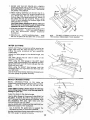
8
TABLE INSERT is removable for removing
installing blades or other cutting tools.
or
WARNIMG: TO AVOID INJURY DUE TO
ACCIDENTAL START, TURN SWITCH "OFF"
AND REMOVE
PLUG
FROM
POWER
SOURCE OUTLET BEFORE
REMOVING
_
'
INSERT.
B.
guard.
A. Raise
Lower blade
the blade
below
• ,
ROUND
# 10 WOOD
HEAD
D.
insertScrew.
from
C. Lift
Loosen
/
front of
SCREWS
28
saw.
front
the table surface,
end,
and
pull
toward
BLADE
GUARD
NOT
SHOWN
FOR PICTURE
NEVER
OPERATE
THE
SAW WITHOUT
THE
PROPER
!NSERT
IN PLACE.
USE THE
SAW
BLADE
iNSERT
WHEN
SAWING,..
USE THE
COMBINATION
DADO
MOLDING
INSERT
(922271) WHEN DADOING
OR MOLDING.
CLARITY
/i
BLOCK
,'
/
ARBOR
,/
i ,,
_H
ARBOR
NUT
/
LOOSE
COLLAR
ARBOR
/
';7.,'>D,
SCREW
TEETH
POINTING
TO _-_
FRONT
OF SAW
9
REMOVING AND iNSTALLiNG
SAWBLADE.
1 O
WARNING:
TO AVOID
iNJURY
DUE
TO
ACCIDENTAL
START, TURN SWITCH "OFF"
AND
REMOVE
PLUG
FROM
POWER
SOURCE
OUTLET
BEFORE REMOVING
OR
iNSTALLiNG
SAWBLADE.
A. Raise Blade
Guard
•,.
remove
I
ARBOR
NUT
_\..._
EXACT-I-CUT
The "yellow"
plastic disc imbedded
in the table
in front
of the sawblade,
is provided
for
marking
the location
of the "sawcut"
on the
workpiece.
A. Check disc . . . if it is above table surface,
place a piece of hardwood
on top of it and tap
it down.
insert.
B. To REMOVE
blade, place a block of wood
against front of blade...
PULL arbor wrench
toward you to LOOSEN arbor nut.
B. With blade 90 ° (square
piece of wood°
to table)
cut
off
a
C. Pull miter gauge back until wood is over disc,
Using very sharp pencil, mark a !ine on disc+
D. With miter gauge
same procedure
disc,
in right hand groove, follow
and mark another
line on
E. These tines indicate
the "path"
(kerf) made by the sawbtade.
WRENCH
ARBOR
/
WOOD
GUARD
__
NOT
SHOWN
FOR PICTURE
line up mark
Use the hold-down
clamp (optional
accessory)
on the miter gauge for greater accuracy.
ARBOR
NUTi/S
BLOCK
BLADE
F. When cutting the workpiece,
workpiece
with line on disc,
of the cut
(___
SHOWN
WITH HOLD-DOWN
CLAMP
(OPTIONAL
ACCESSORY)
CLARITY
C. To TIGHTEN
arbor nut. place a block
of
wood against rear of blade...
PUSH wrench
away from you.
When installing
the blade . . make sure the
teeth are pointing
toward the front of the saw
... and that the blade and collars are clean, and
free from any burrs.
The HOLLOW
side of the collar
must be
against the blade.
Always tighten the arbor nut securely•
NOTE: When using the Dado or Molding Head,
it is not necessary
to install the loose collar.
- BLADE
To replace insert.
Place insert into insert opening
in table and
push toward rear of saw to engage spring clip
and until keyslot in insert wilt drop over screw.
Tighten
screw.
Do not tighten screw to the point where it will
deflect the insert.
29
GUARD
NOT
SHOWN
FOR PICTURE
CLARITY
on
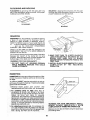
BASIC SAW OPERATmON
WORK
THESE EDGES MuST
BE PARALLEL
HELPERS
/
Before cutting any wood on your saw, study all of
the "Basic Saw Operations".
Notice that in order to make some of the cuts, it is
necessary to use certain devices "Work Helpers"
like the Push Stick, the Push Blockand the Auxiliary
Fence/Work Support, which you can make yourself.
After you have made a few practice cuts, make up
these "helpers" before starting any projects.
Make
the "Push Stick" first.
3/4 PLYWOOD
\
lF'-- 4-3/4 -
PUSH
BLOCK
3/8
J 3/4
MOTE:
All dimensions
AUXILIARY FENCE/WORK
PUSH STICK
-I
1-5/8
_L_
WORKPIECE
1/4
END
1/4
AUXILIARY
WORK
NOTE:
All dimensions
3/8 PLYWOOD
SUPPORT
Make one using a p_ece of 3/8 in and 3/4 in.
plywood.
Fasten together
with glue and
woodscrews.
NOTE: Since the Push Block is used with the
Auxiliary Fence, the 4-3/4 in. dimensions must be
held identical on both the pieces.
NOTCH
"
in inches
in inches
FENCE/
_
SUPPORT
_
3/4 PLYWOOD
!
3-1/2_
27
PUSH STICK AND PUSH BLOCK
Make the Push Stick using a piece of 1 x 2, or rip one
from a wide board, say 11-1/2 in. wide, and set the
rip fence 9-7/8 in. from the sawblade.
Make the Push Block using a piece of 3/8 in. and 3/4
in. plywood.
The small piece of wood 3/8 in. x 3/8 in. x 2-1/2 in.
should be GLUED to the plywood...
DO NOT USE
NAILS. This is to prevent dulling the sawblade in the
event you mistakingly cut into the push block.
Position the handle in the center of the plywood and
fasten together with glue and woodscrews.
%1/4
THIS FACE AND THIS
EDGE MUST BE PARALLEL
3/8 PLYWOOD
NOTE:
All dimension
in inches
"_-.
_.._
5-1/2
USING THE MITER GAUGE
THE
MITER
GAUGE
IS USED
WHEN
CROSSCUTTING,
MITER
CUTTING,
BEVEL
CUTTING,
COMPOUND
MITER
CUTTING,
DADOING
and when RABBETTING
AND
MOLDING across the end of a narrow workpiece
6. Do not stand directly in front of the blade in case
of a THROWBACK (Small cut-off piece caught
by the back of the blade and thrown toward the
operator). Stand to either side of the blade.
7. Keep your hands clear of the blade and out of
the path of the blade.
WARNING: FOR YOUR OWN SAFETY, ALWAYS
OBSERVE
THE
FOLLOWING
SAFETY
PRECAUTIONS
IN ADDITION TO THE SAFETY
INSTRUCTIONS
ON PAGES 2, 3, and 4.
8. If blade stalls or stops while cutting, TURN
SWITCH OFF before attempting to free the
blade.
1. Never make these cuts freehand (without using
the miter gauge or other auxiliary
devices)
because the blade could bind in the cut and
cause a KICKBACK or cause your fingers or
hand to slip into the blade.
9. Do not reach over or behind the blade to pull the
workpiece through the cut.., to support long or
heavy workpieces.., to remove cut-off pieces of
material or FOR ANY OTHER REASON.
10. Do not pickup small pieces of cut,off material
from the table. REMOVE them by pushing them
OFF the table with a long stick. Otherwise they
could be thrown back at you by the rear of the
blade.
2. Always lock the miter gauge securely when in
use.
3. Remove rip fence from table.
5. Have blade extend approximately
1/8 in. above
top of workpiece.
Additional blade exposure
would incre_'se the hazard potential,
KICKBACK.
Turn the saw OFF. After the blade has stopped
turning, lift the guard and remove the piece.
3O
WORKPIECE
1
CROSSCUTTING
CROSSCUTTING
is known as cutting wood across
the grain, at 90 ° , or square with both the edge and
the flat side of the wood. This is done with miter
gauge set at "0".
/ I
it
i
TAB LE
The graduations
on the miter gauge provide
accuracy for average woodworking.
In some cases
where extreme accuracy Js required, when making
angle cuts, for example, make a trial cut and then
recheck it with an accurate square, or protractor.
If necessary, the miter gauge head can be swiveled
slightly to compensate for any inaccuracy.
SANDPAPER
NOTE: The space between the miter gauge bar and
the groove in the table is held to a minimum durin.(
manufacturing.
For maximum accuracy
when using the miter
gauge, always "favor" one side of the groove in the
table. In other words, don't move the miter gauge
from side to side while cutting, but keep one side of
the bar riding against one side of the groove.
NOTE: Glue a piece of sandpaper to the face of the
miter gauge head. This will help prevent the
workpiece from "creeping" while it is being cut.
The Hold-Down
Clamp
(Optional
Accessory)
should be used on the miter gauge for greater
accuracy.
The miter gauge may be used in either of the
grooves in the table. Make sure it is locked.
When using the miter gauge in the LEFT hand
groove, hold the workpiece firmly against the miter
gauge head with your left hand, and grip the lock
handle with your right.
When using the RIGHT Hand groove, hold the
workpiece
with your right hand and the Iockhandle
with your left hand.
AUXILIARY
FENCE/
W'ORK
SUPPORT
When cutting long workpieces, invert AUXILIARY
FENCE/WORK SUPPORT and position it on top of
the guide bars to support the workpieces as near to
the end as possible. If this does not adequately
support the workpiece, you can make a simple
support by clamping a piece of plywood to a
sawhorse.
REPETITIVE
CUTTING
REPETITIVE CUTTING
is known as cutting a
quantity of pieces the same length without having to
mark each piece.
1. Use the Stop Rods (optional accessory) only for
cutting duplicate pieces 6 in. long and longer.
2. DO NOT FEED workpiece with RIGHT Hand,
merely guide it, making sure that it does not bind
or pinch the sawblade.
When making repetitive cuts from a long workpiece,
make sure it is adequately supported.
Use the N old-Down Clamp (Optional Accessory) on
the miter gauge for greater accuracy.
"AUXILIARY
FENCE/
WORK
SUPPORT
31
\
1. NEVER USE THE RIP FENCE AS A LENGTH
STOP BECAUSE THE CUTOFF PI ECE COULD
BiND BETWEEN THE FENCE AND THE BLADE
CAUSING A KICKBACK.
\
\
\
BLOCK
2. When making repetitive cuts shorter than 6 in.,
clamp a block of wood 2 in. long tothe table to act
as a length stop. Do not clamp directly to the
bottom edge of the table because the "swivel" of
the clamp will not grip properly. Place a small
block of wood between the bottom edge of the
table and the "C" clamp.
CAUTION: When clamping the block, make sure
that the end of the block is well in front of the
sswblade. Be sure it is clamped securely.
3. Slide the workpiece along the miter gauge until it
touches the block..,
hold it securely or clamp it
with
the
Hold-Down
Clamp
(Optional
Accessory).
4. Make the cut.., pull the workpiece back ,.. push
the cut off piece off the table with a long !3ush
stick...
DO NOT ATTEMPT TO PICK IT UP AS
THIS COULD ENDANGER YOUR HANDS.
TABLE
MITER
CUTTING
MITER CUTTING is known as
angle other than 90° with the
Follow the same procedure
crosscutting.
Adjust the miter gauge to the
lock it.
cutting wood at an
edge of the wood.
as you would for
desired
TOP VIEW
angle, and
The miter gauge may be used in either of the
grooves in the table.
When using the miter gauge in the LEFT Hand
groove, hold the workpiece firmly against the miter
gauge head with your left hand, and grip the lock
knob with your right.
When using the RIGHT hand groove, hold the
workpiece with your right hand and the knob with
your left hand.
Use the Hold-Down Clamp (Optional Accessory) on
the miter gauge for greater accuracy.
i
BEVEL
CROSSCUTTING
WORKPIECE
BEVEL
CROSSCUTTING
is the
same as
crosscutting except that the wood is also cut at an
angle ... other than 90° with the flat side of the
wood.
Lower blade to about 2 inches above the table top
before tilting blade. Failure to do this n_ay result in
damage to your saw.
\
\,
Adjust the blade to the desired angle.
Use the Miter Gauge in the groove to the RIGHT of
the blade, it cannot be used in the groove to the
LEFT because the blade guard will ir_terfere. Hold
the workpiece with your right hand and the
iockhandle with your left hand.
Use the AUXILIARY FENCE/WO
additional support of the workpiece.
"\,
"
Use the Hold-Down Clamp (Optional Accessory} on
the miter gauge for greater accuracy.
32
COMPOUND
COMPOUND
miter cutting
MATER
made at an angle other than 90 ° to both the edge
and the flat side of the wood.
CUTTING
MITER CUTTING is a combination of
and bevel crosscutting.
The cut is
Adjust the miter gauge and the blade to the desired
angle ... Make sure miter gauge is locked.
USgNG THE RIP FENCE
5. Have blade extend approximately
1/8 in. above
top of workpiece. Additional blade exposure
would increase the hazard potential.
RIPPING,
BEVEL
RIPPING,
PLOUGHING,
MOLDING,
RESAWING AND RABBETING
are
performed using the RIP FENCE together with the
AUXILIARY
FENCE/WORK
SUPPORT,
PUSH
STICK OR PUSH BLOCK.
6. Do not stand directly in front of the blade in case
of a KICKBACK. Stand to either side of the
blade.
WARNING: FOR YOUR OWN SAFETY, ALWAt'S
OBSERVE
THE
FOLLOWING
SAFETY
PRECAUTIONS
IN ADDITION
TO THE SAFETY
INSTRUCTIONS
ON PAGES 2, 3, and 4.
7. Keep your hands clear
the path of the blade.
of the blade
and out of
8. If ths blade stalls or stops while cutting.
TURN
SWITCH
OFF before
attempting
to free the
blade.
1. Never make these cuts FREEHAND (without
using the rip fence or auxiliary devices when
required) because the blade could bind in the
cut and cause a KICKBACK.
g.
2. Always lock the rip fence securely when in use.
3. Remove miter gauge from table.
4. Make sure blade guard is installed for all thrusawing
type
cuts.
Replace
the guard
IMMEDIATELY
following
completion
of
resawing,
rabbeting,
dadoing,
or molding
operations.
Frequently
check
the action
of the
ANTIKICKBACK
PAWLS by passing
the
workpiece alongside of the spreader while saw
is OFF.
Pull the workpiece TOWARD you. tf the PAWLS
do not DIG into the workpiece and HOLD it...
the pawls
must be SHARPENED.
See
"Maintenance"
section.
Do not reach over or behind the blade to pull the
workpiece through the cut..,
to support long or
heavy workpieces..,
to remove small cut-off
pieces
of
material
or FOR
ANY
OTHER
REASON.
10. Do not pick up small pieces of cut-off material
from the table. REMOVE them by pushing them
OFF the table with a long stick. Otherwise they
could be thrown back at you by the rear of the
blade.
11. Do not remove small pieces of cut-off
material
that may become TRAPPED inside the blade
guard while the saw is RUNNING. THIS COULD
ENDANGER
YOUR
HANDS
or cause
a
KICKBACK.
Turn the saw OFF. After the blade has stopped
turning, lift the guard and remove the piece.
WORKPIECE
RiPPiNG
t
RIPPING is known as cutting a piece of wood with
the grain, or lengthwise. This is done using the rip
fence.
Position the fence to the desired WIDTH OF RIPand
lock in place.
Before starting to rip, be sure
A. Rip Fence is parallel to sawblade.
B. Spreader is properly aligned with sawblade.
C. Antikickback
pawls are functioning properly.
When ripping LONG BOARDS or LARGE PANELS,
always use a work su pport.
A simple one can be made by clamping a piece of
plywood to a sawhorse.
BEVEL
TABLE
t
*
)
__......./J
ALWAYS
SUPPORT
LONG
WORKPIECES
..<
RIPPING
When bevel ripping material 6 in. or narrower, use
fence on the right side of the blade ONLY. This will
provide more space between the fence and the
sawblade for use of a push stick. If the fence is
mounted to the left, the sawblade guard may
interfere with proper use of a push stick.
33
When"WIDTH
OF RIP" is 6 in. and WIDER use your
RIGHT Handto feed the workpiece until it is clearof
the table.
Use LEFT hand ONLY to guide the workpiece
not FEED the workpiece with the left hand.
... do
When "Wi DTH OF RIP" is 2 in. to 6 in. wide USE THE
PUSH STICK to feed the work.
/
When WIDTH OF RIP is NARROWER than 2 in., the
push stick CANNOT be used because the guard will
interfere ... USE the AUXILIARY FENCE/WORK
SUPPORT and PUSH BLOCK,
Attach Auxiliary Fence/Work
with two "C" clamps.
Support
to rip fence
Feedthe workpieceby handalongtheAUXILIARY
FENCEuntilthe endis approx.1 in. pastthe front
edgeof thetable.Continuetofeedusingthe PUSH
BLOCK.
Holdtheworkpiecein positionandinstallthe PUSH
BLOCK by sliding it on top of the AUXILIARY
FENCE/WORK
SUPPORT
(ThisMayRaiseGuard).
BAFFLE
NarrowstripsthickerthantheAuxiliaryFence/Work
Supportmayenterthe guardandstrikethe baffle.
CAREFULLY
raiseguardonlyenoughto clearthe
workpiece.UsePUSHBLOCKto completecut.
AUXILIARY
FENCEr
WORK SUPPORT
CUTTING
PANELS
When cutting panels (whenever fence is positioned
outside of table surface), ALWAYS use the
AUXILIARY FENCE/WORK SUPPORT.
1. Unlock fence and raise rear end.
2. Position AUXILIARY FENCE/WORK SUPPORT
as shown and attach it with two "C" clamps.
/
35
.
J"
PLOUGHING
AND
MOLDING
PLOUGHING is grooving with the grain the long
way of the workpmece, using the fence. USE proper
holddowns and feed devices.
MOLDING is shaping the workplece with the grain
the long way of the workpiece, using the fence. Use
proper hoiddowns and feed devices.
PLOUGHING
MOLDING
RESAWING
RESAWING is a "thru-sawing"
cut made by ripping
a piece of wood through its thickness. Do not
attempt to resaw BOWED or WARPED material.
NOTE: To RESAW a Piece of wood wider than 3-3/8
in.... it will be necessary to remove the blade guard
• . . and use the AUXILIARY
FENCE/WORK
SUPPORT. (See "Work Helpers"),
SMALL
BLOCK
OF WOOD
Clamp it to the table so that the workpiece will
SLIDE EASILY but not TILT or MOVE SIDEWAYS
between the two fences.
i&\
Do not clam p directly to the bottom edge of the table
because the "swivel" of the clamp will not grip
properly. Place a small block of wood between the
bottom edge of the table and the "C" clamp.
WARNING: FOR YOUR OWN SAFETY ...
2. MAKE FIRST PASS TO A DEPTH SLIGHTLY
LESS THAN ONE-HALF THE WIDTH OF THE
BOARD;
KEEP SAME FACE OF BOARD
AGAINST FENCE FOR SECOND PASS AS THE
FIRST PASS.
3. iNSTALL BLADE GUARD IMMEDIATELY UPON
COMPLETION
OF
THE
RESAWING
OPERATION.
1. DO NOT "BACK UP" (REVERSE FEEDING)
WHILE RESAWING BECAUSE THIS COULD
CAUSE A KICKBACK.
RABBETING
RABBETING is known as cutting out a section of the
corner of a piece of material, across an end oralong
an edge.
To make a RABBET requires cuts which do not go
al! the waythrough the material. Therefore the blade
guard must be removed.
FIRST
CUT
1
#,
RAB|
I SECOND
CUT
if
I
1. Remove
blade
guard.
Use caution.
Use
featherboards and push sticks, etc. as required.
2. For rabbeting along an edge (long way of
workpiece) as shown, add facing to rip fence
approximately as high as the workpiece is wide.
Adjust
rip fence and blade to required
dimensions; then make first cut with board flat on
table as any rip (typel cut; make second cut with
workpiece on edge. Follow all precautions, safety
instructions, and operational instructions as for
ripping, or rip type operations, including feather
boards and push stick, etc.
WARNING: FOR YOUR OWN SAFETY, INSTALL
BLADE
GUARD
IMMEDIATELY
UPON
COMPLETION OF RABBETING OPERATION.
3. For,rabbeting across an end, for workpiece 101/2' and narrower make the rabbet cut with the
board fiat on the table using the miter gauge fitted
with a facing. DO NOT use the rip fence.
Rabbet cuts can also be made using the dado head
or molding head.
36
DADOING
instructions
for operating the Dado Head are
contained in booklet furnished with the Dado Head.
The Recommended
Dado Head is listed under
Recommended Accessories in this manual.
The arbor on the saw, is only long enough so that
the widest cut that can be made is 13/16" wide.
o o
It is not necessary to install the outside loose collar
before screwing on the arbor nut. Make sure the
arbor nut is tight.
ALWAYS USE DADO iNSERT LISTED
RECOMMENDED
ACCESSORIES.
UNDER
When using the dado head it will be necessary to
remove the Blade Guard and Spreader. USE
CAUTION.
USE FEATHER BOARDS AND PUSH
STICKS AS REQUIRED.
LOOSE
COLLAR
ARBOR
_L_
T
WARNING: FOR YOUR OWN SAFETY, ALWAYS
REPLACE THE BLADE GUARD AND SPREADER
WHEN YOU ARE FiNiSHED DADOING.
MOLDING
__
CUTTING
REMOVE
SAWBLADE
AND
INSTALL
DADO
HEAD
Instructions
for operating the Molding Head are
contained in a booklet furnished with the Molding
Head.
The recommended
molding head is listed under
Recommended Accessories n this manual.
Always
use Molding
Insert
Recommended Accessories.
Listed
CAUTION. USE FEATHERBOARDS
STICKS, etc. AS REQUIRED
Under
AND
FEATHERBOARDS
Featherboards are not employed during non thrusawing operations when using the miter gauge.
has been
(sawblade,
pushstick,
Use featherboards for all other non "thru-sawing"
operations
(when sawblade
guard
must be
removed). Featherboards are used to keep the work
in contact with the fence and table as shown, and to
stop kickbacks.
pushed
completely
dado head, molding
as in ripping.
Before starting the operation
cutter below table surface):
past
head,
(switch
the
etc.)
"OFF"
(b) Make sure by trial that the featherboards
stop a kickback if one should occur.
Replace the sawblade
thru-sawing
operation
guard as soon
is complete.
and
"C" CLAMPS
SUPPORT
STICK
/
37
will
as the non
:EATHERBOARD
"C"CLAMPS
cutter
with a
(a) Install featherboards so they exert pressure on
the workpiece; be positive they are secure, and
Add 8 inch high flat facing board to the fence, the
full length of the fence.
Mount featherboards to fence and table as shown.
so that leading edges of featherboards will support
workpiece until cut is complete, and the workpiece
WORK
PUSH
WARNING: FOR YOUR OWN SAFETY, ALWAYS
REPLACE THE BLADE GUARD AND SPREADER
WHEN YOU ARE FINISHED MOLDING.
When using the molding head it will be necessary to
remove the Blade Guard and Spreader. USE
USING
SAWARBOR
MOTOR
LUBRICATION
AND
MAINTENANCE
1. The sleeve bearings, in both end shields of the
motor, have been lubricated at the factory with
correct lubricant. No other part of the motor
requires lubrication.
2. Re-lubricate motor bearings in accordance with
the instructions on the nameplate. Be sure to
wipe off dirt or grit if present around oil hole caps
to prevent any possibility
of foreign material
contaminating the oil wicks that supply the
bearings with oil. Use a good grade of medium
weig ht mineral oil, such as automobile engine oil,
SAE 20.
.
3. If disassembly of the motor is necessary, it should
be returned to your nearest Sears retail or mailorder store in order to prevent voiding the
guarantee.
NOTE: The speed of this motor cannot be
regulated or changed.
Every effort should be made to prevent foreign
material from entering the motor. When operated
under conditions likely to permit accumulations
of dust, dirt, or waste within the motor, a visual
inspection should be made at frequent intervals.
Accumulations of dry dust can usually be blown
out successfully.
NOTE: Motors used on wood-working
tools are
particularly susceptible to the accumulation
of
sawdust and wood chips and should be blown out
or "vacuumed" frequently to prevent interference
with normal
motor ventilation
and proper
operation of the centrifugally-operated
starting
switch.
MAINTENANCE
WARNING: TO AVOID iNJURY, TURN SWITCH
"OFF" AND REMOVE
PLUG FROM POWER
SOURCE OUTLET BEFORE MAiNTAiNING
OR
LUBRICATING YOUR SAW.
Do not allow sawdust to accumulate
inside the saw.
Frequently blow out any dust that may accumulate
inside the saw cabinet and the motor.
Frequently clean your cutting tools with Craftsman
Gum and Pitch Remover.
A coat of automobile-type
wax applied to the table
will help to keep the surface clean and allow
workpieces to slide more freely.
If the power cord is worn or cut, or damaged in any
way, have it replaced immediately.
Make sure the teeth of the ANTIKICKBACK
pawls
are always sharp. To sharpen:
1. Identify the dull tooth or teeth. Remove blade
guard.
2. Rotate pawl toward rear of spreader so that teeth
are above top of spreader.
3. Hold spreader with left hand and place pawl over
corner of workbench.
4. Sharpen the dull tooth using a few light strokes of
a fine-cut round file.
38
i!iiiiii!i iiiiiiiiiii!ii!
i ii iiiiii!i i!!i , iii!
LUBRiCATiON
The following parts should be oiled occasionally
with SAE No. 20 or No. 30 engine oil.
1. Tilt screw threads and pivot nut. (First Clean with
Craftsman Gum & Pitch Remover.)
2. Elevation screw threads and pivot nut. (First
Clean with Craftsman Gum & Pitch Remover.)
eventually age and harden so that it wilt not provide
an adequate oil film between the core and casing
liner and must be replaced.
LUBRICATION
PROCEDURES
3. Cradle bearing points.
1. Remove the core from the casing, clean the core
by washing
with
kerosene
or an approved
solvent.
4. Bearing points in guard assembly, miter gauge
and rip fence.
3. Inspect
.
LUBRtCATAON OF FLEXIBLE SHAFT
Flexible shafts do require periodic lubrication
because the core acts as a screw conveyor which
will pump the lubrication to one end of the shaft over
an extended period of operation. The frequency of
lubrication depends on how the saw is used. When
the saw operates continuously for long periods of
time, a lubrication schedule should be developed.
The time period may be every 80 or 100 hours. An
indication that the shaft needs lubrication is when it
becomes noisy. Conversely, when the saw has
limited
and infrequent
use. the grease will
GUARD
.
Dry, the core.
the core for worn or broken
is damaged,
it should be replaced.
If core
"Butter" the entire length of the core with a good
grade of general purpose
bearing grease with a
minimum
operating
temperature
of -40°F and
reassemble
in casing. DO NOT force the grease
into the casing with a grease gun. Too much
grease will affect shaft life because it makes the
core work harder.
®
@
_
l/
_t-
wires.
BEARING
POINTS
RECOMMENDED
ITEM
CAT. NO.
Steel Stand ............................
9-22214
Caster Sets .................
9-22222 or 9-22221
Solid Table Extension .................
9-29957
7 In. Molding Head Set ..................
9-3217
7 In. Molding Head Set ..................
9-3218
7 In. Molding Head ......................
9-3214
Molding/Dado
Insert for 7 in.
Dia. Molding or Dado Head ..........
9-22271
Work Light .............................
9-2480
Sawdust Collection System ............
9-24242
10" Dia. Sawblades with 5/8" Bore . See Catalog
Work Light .............................
9-2481
I{/\1
BEARING
\
POINTS
ACCESSORIES
ITEM
CAT. NO.
7 In. Dia. Adjustable Dado Head
9-3261 - 9-3262 - 9-3263
7 In, Dia. Dado Head ....................
9-3257
Sanding Wheel .......................
9-22723
Miter-Gauge Stop Rods ...............
9-29924
Miter-Gauge Hold-Down Clamp .......
9-29928
Taper Jig ...............................
9-3233
Universal Jig ...........................
9-3235
Powe Tool Know How Handbook
Table Saw ...........................
Cast iron Extension, 12 x 27 inches
Rip Fence Bar ........................
Table Extension Kit ...................
....
9-2918
9-22261
9-29969
9-29968
TROUBLE
SHOOTUNG
WARNING: TO AVOID INJURY, TURN SWITCH "OFF" AND ALWAYS REMOVE PLUG FROM POWER SOURCE
OUTLET BEFORE TROUBLESHOOTING.
TROUBLE
SHOOTING
== GENERAL
TROUBLE
PROBABLE CAUSE
REMEDY
Excessive vibration.
1. Blade out of balance.
1. Discard
Cannot make square
Cut when crosscutting.
1. Miter gauge not adjusted
properly.
1. See "Adjusting
Cut binds, burns or
1. Sharpen or replace blade.
stalls motor when
1. Dull blade with improper
tooth set.
ripping.
2. Blade is Heeling.
2. See "Heeling Adjustment ..."
3. Make sure concave or hollow side is facing
3. Warped board.
"down,"
Blade and use a different
blade.
Miter Gauge."
feed slowly.
4. Rip fence not parallel
to blade.
4. See "Aligning
Rip Fence"
5. Spreader out of
5. See "Aligning
Spreader."
alignment.
Cut not true at 900
or 45 ° positions.
Tilt and elevating
handwhee! turn hard.
1. Stop screws not properly
adjusted.
1. See "Blade Tilt", or "Squareness
to Table."
1. Sawdust on threads oftitt
1. See "Maintenance
screw or elevating screw.
and Lubrication"
section.
2. See "Tilt Mechanism."
2. Bearing retainers
•
of Blade
too tight.
TROUBLE
SHOOTING--
MOTOR
NOTE: Motors used on wood-working tools are particularly susceptible to the
accumulation of sawdust and wood chips and should be blown out or "vacuumed"
frequently to )revent interference with normal motor ventilation.
TROUBLE
Excessive noise.
REMEDY
PROBABLE CAUSE
1. Motor.
1. Have motor checked by qualified
technician.
service
Repair service is available at
your nearest Sears store.
Motor fails to develop
' full power. NOTE:
LOW VOLTAGE:
1. Do not use other appliances
t. Circuit overloaded with
lights, appliances
other motors.
same circuit
and
decreases rapidly with " 2. Undersize wires or circuit
decrease in voltage at
too long.
or motors on
when using the saw.
2. increase wire sizes, or reduce length of
wiring. See "Motor Specification
output.)
4O
and
TROUBLE
SHOOTING
-= MOTOR
{Continued)
TROUBLE;
PROBABLE CAUSE
Motor starts slowly
or fails to come up
1. Low voltage will not
trip relay.
1. Request voltage check from the power
company.
to full speed.
2. Windings
2. Have motor repaired or replaced.
REMEDY
burned out
or open.
3. Starting relay not
3. Have relay replaced.
operating,
Motor overheats.
1. Motor overloaded.
2. Improper cooling. (Air
circulation restricted
t.
2. Clean
operate.
out sawdust
circulation
through motor due to
sawdust.
Starting switch in
motor will not
Feed work slower
through
See "Maintenance
into
blade.
to provide
normal
air
motor.
and Lubrication"
section.
1. Burned switch contacts
(due to extended hold-in
1. Have switch replaced and request a voltage
check from the power company.
periods caused by low
line voltage, etc.)
2. Shorted capacitor
2. Have capacitor
defective.
3. Loose or broken
tested and replace if
3. Have wiring checked and repaired.
connections.
Motor stalls
1. Starting switch not
1. Have switch replaced.
(resulting in blown
fuses or tripped
operating.
2. Voltage too low to permit
motor to reach operating
2. Request voltage check from the power
speed.
3. Fuses or circuit breakers
do not have sufficient
3. Install proper size fuses or circuit breakers.
circuit
breakers).
company.
capacity.
Frequent opening of
fuses or circuit
breakers.
1. Motor overloaded.
2. Fuses or circuit breakers
do not have sufficient
capacity.
3. Starting switch not
operating
1. Feed work slower into blade.
2. Install proper size fuses or circuit breakers.
3. Have switch replaced.
(motor does
not reach speed).
4!
21
25
4
16
28
_
11
15 14
12
47
/
,/
15 14
45
_
I
46
48
36
37'
35
[
34
7
33
/
_-----52
Figure
1
29
/
PARTS
LiST FOR CRAFTSMAN
10 iNCH
FIGURE
Key
Part
No.
No.
16
17
18
19
2O
21
22
23
24
25
26
62894
STD532507
62886
60538
62863
STD502505
STD541025
STD551225
9414920
62866
STD541625
STD523110
62541
STD551131
STD541031
60388
62718
62873
STD501102
133645
62773
62748
60534
62493
62710
62709
27
28
60381
STD551031
1
3
4
6
7
8
9
10
11
12
13
14
15
Guard Assembly, Saw (See Fig. 5)
*Bolt, Carriage 1/4-20 x 3/4
Support, Spreader
Nut, Twin
, Bracket, Spreader
Screw, Hex Soc. Set 1/4-20 x 1
*Nut, Hex 1/4-20
*Lockwasher, External 1/4
Washer, 17/64 x 5/8 x 1/32
Clamp, Spreader
*Nut, Wing 1/4-20
*Screw, Hex Hd 5/16-18 x 1
Bar, Fence Rear
* Lockwasher, External 5/16
*Nut. Hex Jam 5/16-18
Nut, Self Threading
Clip, Retaining
Insert Assembly (Includes Key Nos. 16 & 18)
*Screw, Locking Set 10-32 x 3/16
Screw, Flat Cross 10-32 x 1
* Standard
3)
#15)
1
SAW MODEL
29
30
31
32
33
34
35
36
37
38
39
40
41
42
43
44
45
46
47
48
49
50
51
52
Part
No.
STD523107
STD523117
62539
62704
STD511107
STD551210
62689
62888
9426307
62892
62875
62864
446188
62867
803744-1
STD522510
62855
STD533107
60465
423567
71165
37837
37887
37836
62868
62889
62890
62891
6)
Hardware
NO, 113,241680
1
-Key
NO.
Description
Fence Assembly,
Rip (See Fig.
Rod, Separation
(Includes
Key
Screw, Hex Soc. Set 5/16-18 x
Insert, Exact-I-Cut
Tape, Fence
Bar Assembly,
Fence Guide
(Includes
Key #24)
Outlet, On/Off
Power (See Fig.
*Washer,
21/64 x 5/8 x 1/16
TABLE
Item --_ May Be Purchased
Description
*Screw, Hex Hal. 5/16-18 x 5/8
*Screw, Hex Hd. 5/16-18 x 1-3/4
Spacer, Fence Guide Bar
Gauge Assembly, Miter (See Fig. 4)
*Screw, Pan Cross 10-32 x 3/4
*Lockwasher, External No. 10
Handwheel Assembly
Trim, Front
Screw, Pan Cross Type "T" No. 8 x 1/2
Base Assembly
Mount, Motor
Bracket, Shaft
Washer, 17/64 x 3/4 x 1/16
Connector, Motor (Includes Key #43)
Key, 3/16 Square x 5/8
*Screw, Hex Hd. 1/4-20 x 1
Motor (See Fig. 9)
*Bolt, Carriage 5/16-18 x 3/4
Washer, 21/64 x 47/64 x 1/16
Screw, Sems 3/8-16 x !/2
Tie, Wire
Wrench
Hex "L" 5/32
Wrench Hex "L" 1/8
Wrench Hex "L" 3/32
Owners Manual
(Not Illustrated)
Bag of Loose Parts (Not Illustrated)
Bag of Loose Parts (Not Illustrated)
Bag of Loose Parts (Not Illustrated)
Locally.
PARTS
LIST FOR CRAFTSMAN
10 INCH
TABLE
SAW MODEL
NO. 113.241680
8
6
\
\
51
27
9
7
18
\
50
/'
7
45 46
J
42
/ J52
/
33
1
38
37
36
32
\
26
31
26
30
7
Figure 2
8
29
28
PARTS
LiST
FOR
CRAFTSMAN
10 iNCH
FIGURE
Key
No.
1
2
3
r 4
Part
No.
STD523110
STD551131
62885
60537
5 .62883
62870
STD551210
8 STD601103
9
10
11
12
13
14
15
16
17
18
19
20
21
22
23
24
25
26
ISTD511110
62897
60175
62498
"6362
3540
62869
62882
814579
62880
60535
62878
62862
i STD551031
_37828
62896
STD541411
62881
Description
*Screw, 5/16-18 x 7/6
*Lockwasher, 5/16
Support, Bearing
Washer, .505 x 47/64 x 1/16
Rod, Cradle
Guard, Rear
*Lockwasher, External No. 10
*Screw, Pan Rec. Type "T" 10-32 x 3/8
*Screw, Pan Cross 10-32 x 1
Arbor Assembly
tBlade, Saw 10"
Collar Blade
Nut, Saw Arbor
Wrench, Arbor
Guard, Front
Rod, Cradle
Pin, Drive 1/4 x 5/8
Plate, Stop
Spacer, .505 x 3/4 x 1/4
Nut, Push 1/2
Bracket, Lock
*Washer, .380 x 47/64 x 3/32
Spring, Clamp Screw
Shaft Assembly, Bevel
*Nut, Lock 10-32
Retainer, Bearing
TABLE
SAW
MODEL
NO.
113.241680
2
Key
No.
27
28
29
3O
31
32
33
34
35
36
37
38
39
40
41
42
43
44
45
46
47
48
49
5O
51
52
Part
No.
iSTD601103
'37829
18
,62876
62872
62893
60536
60240
62871
62895
62877
63054
62874
6527
STD581062
3509
STD601103
STD551210
38879
37158
60078
STD551131
62865
62884
62887
STD551012
Description
*Screw, Pan Cross 10-32 x 3/8
Screw, Clamp
Handle
Nut, Bevel Pivot
Indicator, Bevel
Cradle Assembly (Includes Key No. 17)
Bolt, Rd. Hd. Short Square Neck 10-32 x 5/8
Nut, Push 3/8
Housing, Arbor
Shaft Assembly, Elevation
Nut, Elevation
Ring, Retaining 3/4
Link
Ring, Retaining 3/4
*Ring, Retaining 5/8
Bearing, Ball
*Screw, Pan Cross Type "T" 10-32 x 3/8
*Lockwasher, External No, 10
Ring, Retaining
Ring, Retaining 5/8
Screw, 5/16-18 x 1/2
*Lockwasher 5/16
Bracket, Stop
Shaft, Flexible
Table
*Washer 17/64 x 7/16 x 1/32
* Standard Hardware Item -- May Be purchased locally.
1"Stock Item - May be secured through the Hardware Department
of most Sears Retail Stores or Catalog Order Houses.
PARTS
LIST FOR CRAFTSMAN
10 iNCH
TABLE
SAW MODEL
NO, 113.24t680
10
FIGURE
3 -- 62773 FENCE
ASSEMBLY
Description
-
62773
= Fence Assembly', Rip
3
STD551031
* Washe r
Key No. 1)
, 21/64 I.D.
1/4
* Standard
Hardware Item =-- May Be Purchased Locally.
46
11
PARTS
LiST FOR CRAFTSMAN
10 iNCH TABLE SAW MODEL
"-------4
FIGURE
Part
No.
Key
No.
1
2
62704
62693
62692
3
4
STD551031
37893
5
6
7
8
9
10
,
4 --
_ 11
12
13
14
MITER
GAUGE
,
ASSEMBLY
Description
+Gauge Assembly, Miter
Plug, Button
Knob, Miter Gauge
(Included Key No. 1)
*Washer, Plain 21/64 x 1 x 1/16
Gauge, Miter
*Screw, Pan Hd. 8-32 x 5/16
ISTD510803
Indicator
L135
Block, Miter Gauge Indicator
37895
37896
Pin, Miter Gauge Stop
*Screw, Pan Hd.,
9417295
w/Lockwasher 8-32 x 5/8
Rod Assembly, Miter Gauge,
162230
" Consisting of Items 11, 12, 13
I STD541231 *Nut, Hex., 5/t6-18
62225
' Stud, Clap
m
62383
Stud, Pivot
60288
Screw, Locking Set
I
I 1/4-20 x 3/8
47
NO. 113.241580
LiST FOR CRAFTSMAN
10 raNCH TABLE
SAW MODEL
!
3
4
2
\
FIGURE
]Key"
\
5 m ON/OFF
Part
t No.
POWER
OUTLET
60381
"
Description
P
=
m
60381
1
2
3
60375
60380
!60256
J oOn/Off Power Outlet Complete
_
Cord, Molded
Housing, Switch
Key, Switch
• Does Not Include
Order Separately
48
NO. 113,24168G
PARTS
LIST FOR CRAFTSMAN
10 iNCH TABLE SAW MODEL
3
1
2
8
7
10
2
FIGURE
Key
No.
1
2
k 3
4
5
6
7
8
9
10
11
12
6 m GUARD
Part
No.
ASSEMBLY
Description
62894
Guard, Assembly, Saw
60297
Nut, Push
62391
Pin 1/4 x 1-1/2
62395
Support, Guard
62389
Guard, Saw
62390
Pin, 1/4 x 1-3/4
STD5510251*Washer, 17/64 x 5/8 x 1/16
62520
Spacer, Pawl
62879
Pawl
52861
Spreader, Blade
62410
Pin, 1/4 x 1-3/64
STD571810 *Pin, Roll, 3/16 x 15/16
B2519
" Spring, Pawl
49
NO, 113=241680
PARTS
LiST FOR CRAFTSMAN
10 iNCH
FIGURE
I
2
6
5
TABLE SAW MODEL
7 -- LEGS
Key
No,
4
Part
No.
Description
60314
2
J
Part
Key
No.
62752
i
No.
I
Screw,
1/4-20
2 62552
3 62554
4 STD551225
5 STD541025
6 62553
7 STD541250
8 803835
HARDWARE FOR
9 STD523112
10 STD551031
11 STD551131
12 STD541031
\
FIGURE
8 --
NO, 113.24!580
TABLE
EXTENSION
Serrated
x 5/8
Leg
Stiffener,
Side
*Lockwasher,
Ext.
*Nut, Hex 1/4-20
Stiffener,
End
*Nut, Hex 1/2-13
Foot, Leveling
Hd.
1/4
ATTACHING LEGS TO SAW.
*Screw, Hex Hd. 5/16-18x 1-1/4
Washer, 11/32 x 1t/16 x 1/16
*Lockwasher, Ext. 5/16
*Nut, Hex 5/16-18
Bag of Loose Parts For Legs
(not illust.)
62589
.....
Description
i
5
5O
Truss
PARTS
LiST
FOR CRAFTSMAN
10 iNCH TABLE
SAW MODEL
NO. 113.241680
NOTE:
4 \
ANY ATTEMPT TO REPAIR THiS MOTOR
MAY CREATE A HAZARD UNLESS
REPAIR IS DONE BY QUALIFIED
SERVICE TECHNICIAN.
_)_..---5
REPAIR SERVICE IS AVAILABLE
AT YOUR NEAREST SEARS STORE.
3
+?
FIGURE
Key
No.
9 -- 62855 MOTOR
PaN
No.
Description
,i
1
60306
Screw, 8-32 x 3/8, Thread
Cutting,
Hd.
64088
37588
37587
3
4
Slotted,
Cover, Terminal
Capacitor
Cover, Capacitor
5 .64142
i
" Screw, 10-32 x 3/16, Thread
Forming, Serrated Hd.
I Cord with Plug
+
!
J
I
Serrated
,
,,,
i¸ •
511
10 iNCH
FLEX DRIVE TABLE SAW
SERVICE
MODEL NO,
113.241680
Now that you have purchased your 10-inch table saw should a
need ever exist for repair parts or service, simply contact any
Sears Service Center and most Sears, Roebuck and Co. stores.
Be sure to provide all pertinent facts when you call or visit.
The model number of your
at the rear of the base.
10-inch
table
saw will be found
SAW WITH LEGS
TWO TABLE EXTENSIONS
AND MOTOR
WHEN ORDERING
REPAIR
FOLLOWING
INFORMATION:
PARTS
Part No. 62868
GIVE
PART
MODEL NUMBER
113.241680
NAME OF ITEM
10-INCH
FLEX DRIVE
All parts listed may be
and most Sears stores.
locally, your order will
Repair Parts Distribution
Sold by SEARS,
ALWAYS
PART NUMBER
HOW TO ORDER
REPAIR
PARTS,
ROEBUCK
AND
DESCRIPTION
TABLE
SAW
ordered from any Sears Service Center
If the parts you need are not stocked
be electronically
transmitted
to a Sears
Center for handling.
CO., Chicago,
Form No. SP4768-3
THE
IL. 60684
Printed
U.S.A.
in U.S.A. 11/85