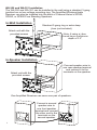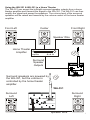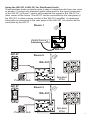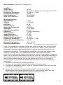
1
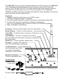
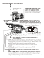
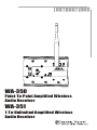
RST
Link
Aria
TM
TM
By C H A N N E L V I S ION
Amplified Wireless Audio Receiver
Spkrs Active Local In
IR In
24VDC
WA-350
Point-To-Point Amplified Wireless
Audio Receiver
WA-351
1-To-Unlimited Amplified Wireless
Audio Receiver
10
The WA-350 Point-To-Point Amplified Wireless Audio Receiver and WA-351
1-To-Unlimited Amplified Wireless Audio Receiver work with Channel
Vision’s WA-320 and WA-321 to create distributed audio systems without
the need for running wires from one room to another. The integrated
100Watt amplifier is ideal for powering distributed audio speakers as well as
wireless home theater applications.
Features:
! Receive wireless audio from up to 300ft. away
! 100Watt integrated class D amplifier
! Pre-amp audio outputs for easy connection to powered subwoofer
! Local audio input to override the wireless audio signal
! Input for compatibility with Channel Vision’s CAT5 audio systems
! Easy installation and linking
Antenna... Receives RF signal from the transmitter
Reset Button... Press to reset receiver
Link LED... Indicates when receiver is linked to a
transmitter
Link Button... Press to complete the linking
process after the link button has been pressed on
the transmitter
Power In... Connect power supply here
IR Input... Connect IR receiver
such as IR-2400 here (optional)
Local Audio In... Line-level
audio sensing input that
overrides the primary
wireless or CAT5 audio
Link
Speaker Outputs...
Connect speakers here
RST
Aria
TM
TM
B y C H A N N E L V I S ION
Amplified Wireless Audio Receiver
Accessories
Speaker Terminal
Connectors
Screws
Power Supply
2
Spkrs
Active Local In
IR In
24VDC
Rear Panel Features and Connections:
WA-350/WA-351
Rear View
WA-350/WA-351
Top View
Left & Right Audio Trim Pots...
Control the maximum output
level of the amplifier. If audio
input level is quiet, the trim pots
will have little noticeable effect.
Volume Jumper... Set J6 to pins 1&2 to
select default power up volume. Set J6 to
pins 2&3 to select previous volume level on
power up. (J7 is currently not implemented)
Jumper 17 & 18 Locations
CAT5
Audio
Input
RCA
Output
J18 Pin 1
J17 Pin 1
Rear Speaker Outputs... Connect in-wall speakers
to these jacks
RCA outputs... Connect to powered subwoofer or
external amplifier
J17 & J18 Input Select Jumpers... Set J17 and J18 to pins 1&2 to
allow primary input from the wireless audio receiver, or to pins 2&3
to allow primary input from the CAT5 audio jack. The wireless audio
and CAT5 audio inputs cannot be used simultaneously.
The front RCA inputs will always function as a local source
override.
CAT5 Audio Input... Connect the output of your CAT5
audio hub here
Keypad Input... Connect an IR control keypad, such as A0127,
here
24VDC Power Input... These terminals allow the power supply to
be connected from the rear of the unit. When these terminals are
used, the front power connection should not be used. Follow the
voltage polarity markings on the screw terminals.
3
IMPORTANT SAFETY INSTRUCTIONS
1. Read these instructions.
2. Keep these instructions for future reference.
3. Heed all warnings.
4. Follow all instructions.
5. Do not use this device near water.
6. Clean only with a dry cloth.
7. Do not block any ventilation openings. Install in accordance with these
instructions.
8. Do not install near any heat sources such as radiators, heat registers,
stoves, or other apparatus (including amplifiers) that produce heat.
9. This apparatus must not be exposed to dripping or splashing liquid and no
objects filled with liquids, such as vases, shall be placed on the
apparatus.
10. Protect the power cord from being walked on or pinched particularly at
plugs, convenience receptacles, and the point where they exit from the
apparatus.
11. Unplug this apparatus during lightning storms or when unused for long
periods of time.
12.
CAUTION
RISK OF ELECTRIC SHOCK
DO NOT OPEN
!
Warning: To reduce the risk of electric shock, do not remove the cover (or
back), no user serviceable parts inside, refer servicing to qualified service
personnel.
Accessories & Complementary Products (sold separately)
A0127 ... IR repeating keypad. The A0127 contains the IR
codes to operate the volume controls in the Amplified Wireless
Audio Receiver. You may also use a standard IR receiver or a
3rd party keypad. When using a simple IR receiver, you will
need to use the A0505 remote control which contains the IR
codes to control the WA-350, WA-351, and A0350. IR codes
can be downloaded from www.channelvision.com, or learned
from an A0505 remote control.
Vid 1
Vol
+
Vid 2
Vid 3
Vol
-
Vid 4
Pwr
Mute
VOL
POWER
S
O
U
R
C
E
TM
1
2
3
4
MUTE
C HANNEL V ISION
MODEL
A0501
ZONE
POWER
A0501, A0502, or A0505 ... Remote control. Contains IR
codes for controlling the Amplified Wireless Audio Receiver as
well as many other Channel Vision audio products.
IR-2400 ... Plasma-Proof IR receiver.
In-wall, In-ceiling Speakers, and Free Standing
Speakers... Channel Vision offers a full line of premium
speakers. These speakers are perfect for whole-house music
or home theater applications.
4
Linking the WA-350 to the WA-320
The WA-350 and WA-320 operate on a 1-to-1 basis and therefore they must be
“Linked” to each other prior to the first use. Once linked they will maintain their
paired status even if a power loss occurs. The “RST” button can be used to
reset and separate a linked pair.
Make sure audio is playing into
the WA-320.
Press and hold the Link button
for 3 seconds to begin the linking
process.
The green PWR/LINK LED will
turn orange.
If you encounter interference,
press the link button on the
WA-320 to skip to a different
broadcast channel.
Press the link button on the
receiver within 6 seconds to
complete the process.
Note: The green LINK LED
will blink until the receiver
has been linked.
WA-350
WA-320
Link
RST
Aria
TM
TM
B y C H A N N E L V I S I ON
Amplified Wireless Audio Receiver
Spkrs
Active Local In
IR In
24VDC
Linking the WA-351 to the WA-321
The WA-321 and WA-351 operate on a 1-to-Unlimited broadcast basis. When
the WA-351 is within range of the WA-321, it will automatically detect and
receive the audio signal. If distortion or reception problems occur, press the
“Link” button on the WA-321 to change the broadcast channel. There are 8
possible broadcast channels to choose from.
The WA-351 will automatically
detect the broadcast signal of
The WA-321 can broadcast
the WA-321.
on 8 different channels. If you
encounter interference,
press the link button on the
WA-321 to skip to a
different broadcast channel.
WA-321
WA-351
Link
RST
Aria
B y C H A N N E L V I S ION T M
Amplified Wireless Audio Receiver
Spkrs
Active Local In
IR In
24VDC
5
WA-350 and WA-351 Installation
The WA-350 and WA-351 can be installed in the wall using a standard 3-gang
junction box or low-voltage mounting ring. The Amplified Wireless Audio
Receiver can also be installed into the back of Channel Vision’s SP525,
SP650, or SP800 Free Standing Speakers.
In-Wall Installation
Standard 3-gang ring or extra deep
j-box (not included)
Attach unit with the
provided screws
Note: if using a j-box,
it must have a minimum
depth of 3.5”
RST
Aria
B y C HA NNE
Amplified Wire
Spkrs Activ
e Local
In
IR In
L V I S ION TM
less Audio Rece
iver
24VDC
In-Speaker Installation
Connect speaker wire to
one rear speaker terminal
and connect it to the
terminals on the speaker.
Attach unit with the
provided screws
RST
Aria
By CHANN
EL VI
SI ON
Amplified W
ireless Audio
Receiver
Spkrs Active
Local In
IR In
TM
24VDC
One Amplified Receiver can serve one pair of speakers.
Connect a second
speaker wire to
one front speaker
terminal and connect
the other end to the
terminals on the
second speaker.
6
RST
A ri a
By CH ANN
E L VI SI
SI O N
Amplified Wir
eless Audio
Receiver
Spkrs Activ
e Local
In
IR In
24VDC
TM
Using the WA-321 & WA-351 in a Home Theater
The WA-321 can accept the left/right surround speaker outputs from a home
theater amplifier and transmit the signal to the WA-351. The WA-351 can then
amplify the signal and power the speakers. The volume level of the surround
speakers will be raised and lowered by the volume control of the home theater
amplifier.
Center
Front Left
Front Right
Speaker Wire
Home Theater
Amplifier
Amplifier
Surround
Speaker
Outputs
Surround speakers are powered by
the WA-351, but the volume is
controlled by the home theater
amplifier.
WA-321
WA-351
Surround
Left
Link
RST
Surround
Right
Aria
TM
By C H A N N E L V I S ION
Amplified Wireless Audio Receiver
Spkrs
Active Local In
IR In
24VDC
Speaker Wire
7
Using the WA-320 & WA-350 in a Home Theater
The WA-320 can accept the 5.1 outputs from a home theater amplifier and
transmit the signal to several WA-350 Wireless Audio Receivers. The WA-350’s
can then amplify the signal and power the speakers. The volume level of the
surround speakers will be raised and lowered by the volume control of the
home theater amplifier.
Center
Behind TV
WA-350
Front Left
Link
Front Right
RST
Link
Aria
Aria
By C H A N N E L V I S IO N TM
Active Local In
IR In
TM
TM
B y C H A N N E L V I S IO N
Amplified Wireless Audio Receiver
Spkrs
RST
Amplified Wireless Audio Receiver
24VDC
Active Local In
Spkrs
IR In
24VDC
Powered Sub
Center & Sub
Line Outputs
Front Left/Right
Speaker Outputs
Home Theater
Amplifier
Amplifier
Surround
Speaker WA-320
Outputs
Surround
Left
WA-350
Link
RST
Aria
TM
TM
B y C H A N N E L V I S IO N
Amplified Wireless Audio Receiver
Spkrs
Active Local In
IR In
24VDC
Speaker Wire
8
Surround
Right
Using the WA-321 & WA-351 for Distributed Audio
These wireless audio products make it easy to transmit audio from one room
to another. Connect any standard audio component to the input connectors
of the WA-321 in Room 1 which will broadcast the signal to the WA-351 in
other rooms of the home. The A0127 can be connected to the rear panel of
the WA-351 to allow volume control of the WA-351 amplifier. If a powered
subwoofer is connected to the rear panel of the WA-351, its volume will be
controlled by the A0127.
Room 1
Audio Source
WA-321
A0127
Room 2
Vid 1
Vol
+
Vid 2
Vid 3
WA-351
Vol
-
Vid 4
Pwr
Mute
Link
RST
Aria
By C H A N N E L V I S I ON TM
Amplified Wireless Audio Receiver
Spkrs
Active Local In
IR In
Speaker
Wire
24VDC
Powered Sub
A0127
Room 3
Vid 1
Vol
+
Vid 2
Vid 3
WA-351
Vol
-
Vid 4
Pwr
Mute
Link
RST
Aria
By C H A N N E L V I S ION TM
Amplified Wireless Audio Receiver
Spkrs
Powered Sub
Active Local In
IR In
24VDC
Speaker
Wire
9
Troubleshooting:
Problem: Hum in System
Troubleshooting: Plug all parts of the system into the same outlet to see if
the hum goes away.
Cause: The different components in the system are connected to different
electrical grounds. This forces electrical currents to find alternate paths to
ground causing an audible 60Hz hum.
Solution: Plug products into an electrical circuit with a common ground. Lift
the ground with a ground lifting plug.
Problem: Transmitter is not linking with the receiver.
Troubleshooting: Make sure you are linking compatible models (WA-320
with WA-360). Check if pwr/lnk LED indicator on the transmitter is turning
amber and that the signal LED is lit.
Cause: Link button on WA-350 is not being pressed quickly enough. Review
the linking procedure in this manual. Please note that a transmitter and
receiver will remain paired even after being unplugged. This allows you to
complete the linking process before placing the receiver in it’s final location.
Solution: Press the Link button on the WA-320 and confirm that the pwr/lnk
LED turns amber. Within 6 seconds, press the Link button on the WA-350.
Problem: Can’t link to the transmitter, or audio is cutting out.
Troubleshooting: Check the source, is it sending a signal? Consider setting
the jumpers on the transmitter (WA-320/WA-321) to the “disable audiosensing” position during setup procedure (see the Rear Panel Features and
Connections section). This will ensure that the transmitter will not mute
during pauses or very quiet passages.
Cause: Either there is no audio going into the transmitter, or the audio is very
quiet which is causing the transmitter to mute.
Solution: Use a known good audio source. If you can’t find any other
problems, try using a different source component even if you think your audio
source is OK.
10
Specifications: (typical at 25 degrees C)
Amplifier:
Power input:
Output power:
Frequency Response:
Signal to Noise Ratio:
Input Sensitivity:
Auto On Threshold:
24VDC
50 Watts/ch RMS into 6 ohms @ <10% THD
20-20kHz (+/-3dB)
>85dB
500mVRMS
10mVRMS
Wireless Receiver:
Input Voltage:
THD+N:
S/N Ratio:
Audio Latency:
Operating Frequency:
Data Rate:
Audio Sampling Rate:
Channels:
RX Sensitivity:
Image Rejection:
Audio Output Level:
Audio Output Impedance:
Frequency Response:
Adjacent Channel Rejection:
Storage Temperature:
Operating temperature:
5 VDC
0.7% Max
80 dB
3.8 ms
2400 MHz
1.152 Mbps
48 kHz
8 (User Selectable)
-85 dBm
47 dBc
2.6 Vpp
16 Ohm
20-20kHz +/- 3dB
>45 dB
-40 to +85º C
0 to +55º C
Specifications subject to change without notice
Note: This equipment has been tested and found to comply with the limits for a
Class B digital device, pursuant to part 15 of the FCC Rules. These limits are
designed to provide reasonable protection against harmful interference in a
residential installation. This equipment generates, uses and can radiate radio
frequency energy and, if not installed and used in accordance with the
instructions, may cause harmful interference to radio communications. However,
there is no guarantee that interference will not occur in a particular installation. If
this equipment does cause harmful interference to radio or television reception,
which can be determined by turning the equipment off and on, the user is
encouraged to try to correct the interference by one or more of the following
measures:
! Reorient or relocate the receiving antenna.
! Increase the separation between the equipment and receiver.
! Connect the equipment into an outlet on a circuit different from that to which
the receiver is connected.
! Consult the dealer or an experienced radio/TV technician for help.
! Modifications not expressly approved by the manufacturer could void the
user's authority to operated the equipment under FCC rules.
Channel Vision WA-350 Channel Vision WA-351
Tested To Comply
With FCC Standards
FOR HOME OR OFFICE USE
Tested To Comply
With FCC Standards
FOR HOME OR OFFICE USE
11
1
Channel Vision Technology will repair or replace any defect in material
or workmanship which occurs during normal use of this product with
new or rebuilt parts, free of charge in the USA, for one year from the
date of original purchase. This is a no hassle warranty with no mail in
warranty card needed. This warranty does not cover damages in
shipment, failures caused by other products not supplied by Channel
Vision Technology, or failures due to accident, misuse, abuse, or
alteration of the equipment. This warranty is extended only to the
original purchaser, and a purchase receipt, invoice, or other proof of
original purchase date will be required before warranty repairs are
provided.
Mail in service can be obtained during the warranty period by calling
(800) 840-0288 toll free. A Return Authorization number must be
obtained in advance and can be marked on the outside of the shipping
carton.
This warranty gives you specific legal rights and you may have other
rights (which vary from state to state). If a problem with this product
develops during or after the warranty period, please contact Channel
Vision Technology, your dealer or any factory-authorized service
center.
Channel Vision products are not intended for use in medical, lifesaving,
life sustaining or critical environment applications. Channel Vision
customers using or selling Channel Vision products for use in such
applications do so at their own risk and agree to fully indemnify
Channel Vision for any damages resulting from such improper use or
sale.
www.channelvision.com
234 Fischer Avenue, Costa Mesa, California 92626 USA
(714)424-6500 (800)840-0288 (714)424-6510 fax
email: [email protected]
500-235 rev C