1
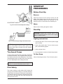
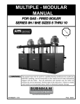
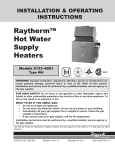
INSTALLATION & OPERATING
INSTRUCTIONS
Raytherm™
Commercial
Swimming
Pool
Heater
Models P-926 to P-1826
L
W
& P-2100 to P-4001
WARNING: If these instructions are not followed exactly, a fire or explosion may
result causing property damage, personal injury or death.
FOR YOUR SAFETY: Do not store or use gasoline or other flammable vapors and
liquids or other combustible materials in the vicinity of this or any other appliance.
To do so may result in an explosion or fire.
WHAT TO DO IF YOU SMELL GAS:
• Do not try to light any appliance.
• Do not touch any electrical switch; do not use any phone in your building.
• Immediately call your gas supplier from a neighbor's phone. Follow the gas
supplier's instructions.
• If you cannot reach your gas supplier, call the fire department.
Installation and service must be performed by a qualified installer, service agency or
the gas supplier.
This manual should be maintained in legible condition and kept adjacent to the heater or in another safe place for
future reference.
CATALOG NO. 6200.51Q
Effective: 11-17-11
Replaces: 05-24-10
P/N 240251 Rev. 18
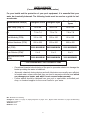
WATER CHEMISTRY
(Corrosive water voids all warranties)
For your health and the protection of your pool equipment, it is essential that your
water be chemically balanced. The following levels must be used as a guide for balanced water.
Fiberglass Pools
Fiberglass Spas
Other Pool & Spa
Types
Water Temp. (Deg. F)
68 to 88
89 to 104
68 to 104
pH
7.3 to 7.4
7.3 to 7.4
7.6 to 7.8
Total Alkalinity (PPM)
120 to 150
120 to 150
80 to 120
Calcium Hardness (PPM)
200 to 300
150 to 200
200 to 400
6000 MAXIMUM
6000 MAXIMUM
6000 MAXIMUM
Free Chlorine (PPM)*
2 to 3
2 to 3
2 to 3
Total Dissolved Solids
(PPM)
3000 MAXIMUM
3000 MAXIMUM
3000 MAXIMUM
Recommended Level(s)
Salt (PPM)
* Free Chlorine MUST NOT EXCEED 5 PPM!
•
•
•
Occasional chemical shock dosing of the pool or spa water should not damage the
heater providing the water is balanced.
Automatic chemical dosing devices and salt chlorinators are usually more efficient
in heated water, unless controlled, they can lead to excessive chlorine level which
can damage your heater, and which is not covered under warranty.
Further advice should be obtained from your pool or spa builder, accredited pool
shop, or chemical supplier for the correct levels for your water.
Rev. 18 reflects the following:
Changes to: Table C on page 12, Piping Diagrams on pages 15-17, Bypass Valve information on page 18, Winterizing
instructions on page 31.
Additions: None
Deletions: None
2
CONTENTS
WATER CHEMISTRY
2
WARNINGS
4
Pay Attention to These Terms
4
RECEIVING EQUIPMENT
5
GENERAL
SPECIFICATIONS
5
INSTALLATION
5
Code Requirements
5
Base Installation
5
Clearances
6
Combustion Air (Indoor Units Only)
6
Venting Connections
7
Gas Supply Connections
8
Water Connections
10
CONTROLS
10
Flow Switch
10
Water Pressure Switch
11
Automatic Chlorinators and Chemical
Feeders
11
Unitherm Governor Operation
11
Companion Flange Connections
(Models 926-1223)
11
Mounting the Poolstat Control with FrontMounted Loop Using Mounting Slots
12
Mounting Well into System Return Loop
Pipe - Front-Mounted Loop
14
Piping Configurations for Raytherm
Commercial Pool Heaters (926-1223)
15
Piping Configurations for Raytherm
Commercial Pool Heaters (1287-1826) 16
Piping Configurations for Raytherm
Commercial Pool Heaters (2100-4001) 17
Temperature Controls
18
External Auxiliary Bypass Valve (Where
Required) Models 926-1223 Only
18
Auxiliary Bypass Valve Adjustment
18
Electrical Wiring
19
Wiring Diagram—Models 926–1223
Wiring Diagram—Models 1287–1826
Wiring Diagram—Models 2100–2500
Wiring Diagram—Models 3001–4001
SERVICING
General Location Of Controls
Temperature Control
Pressure Switch
Pressure Switch Adjustment
Two-Speed Pumps
Pilot Safety
START-UP PROCEDURES
Before Start-Up
Start-Up
After Start-Up
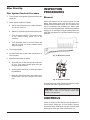
INSPECTION PROCEDURES
Burners
CONTROLS
SERVICING PROCEDURES
Tube Cleaning Procedure (Typical)
Heat Exchanger Reassembly
Burner Drawer Removal
Gas Valve Removal
Main Burner and Orifice Removal
Pilot Removal and Cleaning
Heat Exchanger Removal
Combustion Chamber Removal
Control Well Replacement
Tube Replacement Procedure
Procedure For Cleaning Flue Gas
Passageways
Unitherm Governor Replacement
MAINTENANCE AND CARE
Winterizing Your Heater
TROUBLESHOOTING
WARRANTY
3
20
21
22
23
24
24
24
24
24
25
25
25
25
25
26
26
26
26
27
27
27
27
27
28
28
28
29
29
29
29
30
30
31
32
35
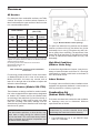
WARNINGS
Pay Attention to These Terms
DANGER:
Indicates the presence of immediate hazards which will cause severe personal injury, death or substantial property damage if ignored.
WARNING:
Indicates the presence of hazards or unsafe practices which could cause
severe personal injury, death or substantial property damage if ignored.
CAUTION:
Indicates the presence of hazards or unsafe practices which could cause
minor personal injury or product or property damage if ignored.
NOTE:
Indicates special instructions on installation, operation, or maintenance which
are important but not related to personal injury hazards.
DANGER: Make sure the gas on which the heater
will operate is the same type as that specified on the
heater rating plate.
CAUTION: Operation of this heater in lowtemperature systems requires special piping.
Harmful internal condensation will occur if the inlet
water temperature does not exceed 105°F. Warranty
claims will be denied when condensation occurs.
WARNING: Should overheating occur or the gas
supply valve fail to shut, do not turn off or disconnect
the electrical supply to the heater. Instead, shut off
the gas supply at a location external to the heater.
CAUTION: If this heater is to be installed above
radiation level, it must be provided with a low water
cut-off device at the time of heater installation.
WARNING - CALIFORNIA PROPOSITION
65: This product contains chemicals known to the
State of California to cause cancer, birth defects or
other reproductive harm.
CAUTION: If this heater is to be installed in a
negative or positive pressure equipment room, there
are special installation requirements. Consult factory
for details.
WARNING: To minimize the possibility of improper
operation, serious personal injury, fire, or damage to
the heater:
•
Always keep the area around the heater free of
combustible materials, gasoline, and other flammable liquids and vapors.
•
Heater should never be covered or have any
blockage to the flow of fresh air to the heater.
WARNING: Do not use this heater if any part has
been under water. Immediately call a qualified
service technician to inspect the heater and to
replace any part of the control system and any gas
control which has been under water.
WARNING: Risk of electrical shock. More than one
disconnect switch may be required to deenergize the
equipment before servicing.
4
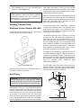
RECEIVING EQUIPMENT INSTALLATION
On receipt of the equipment, visually check for external damage to the carton or the shipping crate. If the
carton or shipping crate is damaged, make a note on
the Bill of Lading and report the damage to the Carrier
immediately. Remove the heater from the carton or
shipping crate. Do NOT use the shipping base crate as
an installation base.
These instructions are intended for the use of qualified
personnel only, specifically trained and experienced in
the installation of this type of heating equipment and
related system components. Installation and service
personnel may be required by some states to be
licensed. If your state is such, be sure your contractor
bears the appropriate license. Persons not qualified
shall not attempt to fix this equipment nor attempt
repairs according to these instructions.
On occasion, we ship some items loose. Be sure that
you receive the number of packages indicated on the
Bill of Lading. When ordering parts, you must specify
Model and Serial Number of heater. When ordering
under warranty conditions, you must also specify date
of installation.
WARNING: Improper installation, adjustment,
alteration, service or maintenance may damage the
equipment, create a hazard resulting in
asphyxiation, explosion or fire, and will void the
warranty.
Raypak recommends that this manual be reviewed
thoroughly before installing your Raypak Pool Heater.
If there are any questions which this manual does not
answer, please contact the factory or your local
Raypak representative.
Code Requirements
Claims for shortages and damages must be filed with
carrier by consignee. Permission to return goods must
be factory authorized and are subject to a stocking
charge.
The heater should not be located in an area where
possible water leakage will result in damage to the
area adjacent to the appliance or to the structure.
When such locations cannot be avoided, it is recommended that a suitable drain pan, adequately drained,
be installed under the appliance. The pan must not
restrict combustion air flow.
Purchased parts are subject to replacement only
under the manufacturer's warranty. Debits for defective replacement parts will not be accepted and will be
replaced in kind only per our standard warranties.
Installation must be in accordance with local codes, or,
in the absence of local codes, with the latest editions
of the National Fuel Gas Code, ANSI Z223.1/NFPA 54,
and National Electrical Code, ANSI/NFPA 70.
GENERAL
SPECIFICATIONS
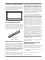
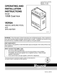
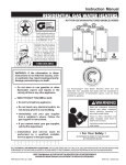
Base Installation
Do NOT use the shipping base crate as an installation
base. Heater must be mounted on a level base, such
as cement slab, cement blocks or other non-combustible surface. An optional non-combustible base is
available for Indoor Models 962 through 1826. An
alternative method for providing a base for combustible floors as illustrated below. Heaters may not be
installed on carpeting.
Models 962, 1125, 1223, 1336, 1468, 1631, 1826 &
2100 through 4001 are specifically designed for indoor
installation ONLY. Models 926, 1083, 1178, 1287,
1414, 1571 & 1758 are specifically designed for outdoor installation ONLY. All heaters are standard with
electronic ignition for both natural and propane applications. Heaters require 120V power supply. Control
circuits operate at 24V, supplied by an internal 120V to
24V transformer.
These heaters are design certified and tested under
the requirements of ANSI Z21.56 / CSA 4.7 American
National Standard for Gas-Fired Pool Heaters. Rated
inputs suitable for up to 2000 feet elevation. For elevations above 2000 feet, reduce input 4% for each 1000
feet above sea level, as high elevation reduces combustion performance.
Fig. 1: Alternate Mounting Base
5
Clearances
All Heaters
For clearances from combustible surfaces, see Table
A below. We require a minimal vertical clearance of
three feet between the upper surface of the flue outlet
to a noncombustible material.
Indoor Heaters
Outdoor Heaters
(926–1758)
Heater
Side
Clearance
(Inches)
Heater
Side
Clearance
(Inches)
Top
24
Top
24
Back
24
Back
24
Right Side
24
Right Side
24
Left Side
24
Left Side
24
Vent*
6
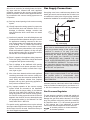
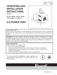
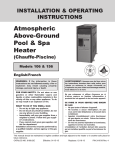
Fig. 2: Minimum Distance from Openings
The point from where the flue products exit the heater
must be a minimum of four (4) feet below, four (4) feet
horizontally from or one (1) foot above any door, window or gravity inlet to a building. The top surface of the
heater shall be at least three (3) feet above any forced
air inlet, or intake ducts located within ten (10 ) feet
horizontally.
*Vent includes factory supplied drafthood and does not include field
supplied vent systems above the drafthood. On Models 2100-4001
drafthood is built into heater.
For servicing provide a front clearance as shown below:
Model 926/962-758/1826 - 24"
Model 2100-4001 - 48"
High Wind Conditions
(Outdoor Units Only)
Table A: Minimum Clearances from Combustible
Construction
In areas where high winds are frequent, it may be necessary to locate the heater a minimum of 3' from high
vertical walls, or install a wind break so the heater is
not in direct wind current.
For servicing, provide at least 24" in front of the heater
on Models 926-1826 & 48" in front of the heater on
Models 2100-4001 for burner tray removal, and at
least 18" on the right side of the heater to inspect and
delime the heat exchanger.
Indoor Heaters
The design is also certified for indoor installation when
equipped with approved drafthood. Locate heater as
close as practical to a chimney or gas vent.
Outdoor Heaters (Models 926-1758)
Combustion Air
(Indoor Units Only)
These heaters are design certified for outdoor installation, when equipped with the approved top designated
for outdoor use. Heaters must not be installed under
an overhang of less than three (3) feet from the top of
the heater. Three (3) sides must be open in the area
under the overhang. Roof water drainage must be
diverted away from heaters installed under overhangs
with the use of gutters.
The heater must have both combustion and ventilation
air. Openings must not be obstructed. Minimum
requirements are as follows:
CAUTION: Combustion air must not be
contaminated by corrosive chemical fumes which
can damage the heater and void the warranty.
WARNING: The heater shall not be located in an
area where water sprinklers, or other devices, may
cause water to spray through the cabinet louvers
and into the heater. This could cause heavy internal
rusting or damage some electrical components, and
this would void the warranty.
1. Free combustion air 1 sq. in. per 1000 BTU input
within 12" of the floor.
6
2. Free ventilation air 1 sq. in. per 1000 BTU input
within 12" of the ceiling level.
must have a minimum of 1/4 inch per foot rise and
should be supported at not more than five foot intervals. Plumbers' tape, criss-crossed, will serve to space
both horizontal and vertical piping.
NOTE: If the room the heater is installed in is
located against an outside wall and air openings
communicate directly with the outdoors, the
openings may be 1/4 the size specified above (ANSI
Z223.1/NFPA 54, latest edition)
Gas vents supported only by the flashing and extending above the roof more than five feet should be
securely guyed or braced to withstand snow and wind
loads. We recommend use of insulated vent pipe
spacer through the roofs and walls.
Venting Connections
For protection against rain or blockage by snow, the
vent pipe must terminate with a vent cap which complies with the local codes or, in the absence of such
codes, to the latest edition of the National Fuel Gas
Code, ANSI Z223.1/NFPA 54.
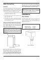
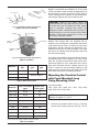
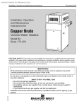
Drafthood (Indoor) Models 962-1826
Locate and assemble as shown in Fig. 3. Secure with
screws supplied in envelope in carton.
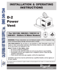
The discharge opening must be a minimum of two feet
vertically from the roof surface and at least two feet
higher than any part of the building within ten feet.
Vent stack shall be at least five feet in vertical height
above the drafthood outlet. The vent cap location shall
have a minimum clearance of 4 feet horizontally from,
and in no case above or below, unless a 4-foot horizontal distance is maintained, from electric meters,
gas meters regulators and relief equipment.
The weight of the vent stack or chimney must not rest
on heater drafthood. Support must be provided in
compliance with applicable codes. The heater top and
draft hood must be readily removable for maintenance
and inspection. Vent pipe should be adequately supported to maintain proper clearances from
combustible construction.
Type "B" double wall or equivalent vent pipe is recommended. However, single wall metal vent pipe may be
used as specified in the latest edition of the National
Fuel Gas Code ANSI Z223.1/NFPA 54.
Fig. 3: Indoor Draft Hood
Models 2100-4001 have built-in drafthoods that must
be properly vented to the outside.
10' OR LESS
VENT CAP
Vent Piping
2' MIN
2' MIN
WARNING: Indoor heater requires a drafthood that
must be connected to a vent pipe and properly
vented to the outside. Failure to follow this procedure
can cause fire or fatal carbon monoxide poisoning.
5' MIN
VENT PIPE
Vent piping the same size or larger than the draft hood
outlet is recommended, however, when the total vent
height is at least ten (10) feet (drafthood relief opening
to vent terminal), the vent pipe size may be reduced
as specified in the National Fuel Gas Code, ANSI
Z223.1/NFPA 54 - latest edition. Avoid long horizontal
runs of vent pipe and too many elbows. If installation
requires horizontal or non-vertical runs, the vent pipe
DRAFT HOOD
HEATER
Fig. 4: Venting Clearances
7
Gas Supply Connections
At the time of removal of an existing heater, the following steps shall be followed with each appliance
remaining connected to the common venting system
placed in operation, while the other appliances remaining connected to the common venting system are not
in operation.
Gas piping must have a sediment trap ahead of the
heater gas controls, and a manual shut-off valve located outside the heater jacket. All gas piping should be
tested after installation in accordance with local codes.
(a) Seal any unused openings in the common venting
system.
(b) Visually inspect the venting system for proper size
and horizontal pitch and determine there is no
blockage or restriction, leakage, corrosion and
other deficiencies which could cause an unsafe
condition.
MANUAL
SHUT-OFF
VALVE
(c) Insofar as is practical, close all building doors and
windows and all doors between the space in which
the appliances remaining connected to the common venting system are located and other spaces
of the building. Turn on clothes dryers and any
appliance not connected to the common venting
system. Turn on any exhaust fans, such as range
hoods and bathroom exhausts, so they will operate at maximum speed. Do not operate a summer
exhaust fan. Close fireplace dampers.
SEDIMENT
TRAP
Fig. 5: Gas Piping
CAUTION: The heater and its manual shut-off
valve must be disconnected from the gas supply
during any pressure testing of that system at test
pressures in excess of 1/2 psig (3.45 KPA).
Dissipate test pressure in the gas supply line before
reconnecting the heater and its manual shut-off
valve to gas supply line. FAILURE TO FOLLOW
THIS PROCEDURE MAY DAMAGE THE GAS
VALVE. OVER PRESSURIZED GAS VALVES ARE
NOT COVERED BY WARRANTY. The heater and its
gas connections shall be leak tested before placing
the appliance in operation. Use soapy water for leak
test. DO NOT use open flame.
(d) Place in operation the appliance being inspected.
Follow the lighting instructions. Adjust thermostat
so appliance will operate continuously.
(e) Test for spillage at the drafthood relief opening
after 5 minutes of main burner operation. Use the
flame of a match or candle, or smoke from a cigarette, cigar or pipe.
CAUTION: Do not use Teflon tape on gas line pipe
thread. A pipe compound rated for use with natural
and propane gases is recommended. Apply
sparingly only on male pipe ends, leaving the two
end threads bare.
(f) After it has been determined that each appliance
remaining connected to the common venting system properly vents when tested as outlined above,
return doors, windows, exhaust fans, fireplace
dampers and any other gas burning appliance to
their previous conditions of use.
A minimum of 7 in. WC and a maximum of 10.5 in. WC
upstream pressure under load, and no load conditions
must be provided for natural gas or a minimum of 11
in. WC and a maximum of 13 in. WC for propane gas.
(g) Any improper operation of the common venting
system should be corrected so the installation
conforms with the latest edition of the National
Fuel Gas Code, ANSI Z223.1/NFPA 54. When resizing any portion of the common venting system,
the common venting system should be re-sized to
approach the minimum size as determined using
the appropriate tables in the National Fuel Gas
Code, ANSI Z223.1/ NFPA 54.
Gas Pressure Regulator
The gas pressure regulator is preset and sealed at 4
in. WC for natural gas, and 11 in. WC for propane gas.
Between the gas valve and the burners is a 1/8" pipe
plug. The pressure at this point, taken with a manometer, should be about 3.7 in. WC natural gas and 10.5
in. WC propane gas. If an adjustment is needed,
remove seal and turn adjustment screw clockwise
, to increase pressure or counter-clockwise
, to decrease pressure.
For special venting applications that require reduced
vent sizes and through the wall venting, the optional D
Series Power Vent can be used. Consult the factory or
your local Raypak representative.
8
Gas Code. Under NO circumstances shall bleed lines
terminate in the gas utilization equipment flue or
exhaust system.
MANOMETER
MANUAL
SHUTOFF
VALVE
GAS PRESSURE
TEST UPSTREAM
GAS PRESSURE
TEST AT GAS
VALVE
GAS PRESSURE TEST
AT HEATER
Fig. 6: Gas Pressure Test Points
Venting of Diaphragm Gas
Components
Bleed Line
Connection
Heaters with gas train components that have
diaphragms in their construction are supplied with a
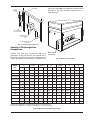
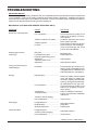
bleed line connection that must be connected to the
outside atmosphere as required by the National Fuel
Model
No.
1”
N
1-1/4”
Fig. 7: Bleed Line Connection
1-1/2”
2”
2-1/2”
P
N
P
N
P
N
P
N
926/962
15
20
45
45
110
150
360
400
1083/1125
10
15
35
35
80
120
300
300
1178/1223
25
25
60
85
220
200
1287/1336
25
20
55
75
180
1414/1468
20
15
45
65
1571/1631
15
15
35
1758/1826
15
10
2100
10
10
3”
P
N
170
325
560
150
165
300
500
50
20
125
250
400
30
40
100
100
225
340
25
30
80
75
175
260
2500
15
20
55
55
135
3001
10
15
35
40
3500
10
30
4001
5
20
P
N
160
400
600
85
120
250
500
30
45
80
200
400
600
25
35
65
160
300
400
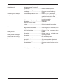
Natural Gas, 1000 BTU/FT3 .60 Specific Gravity @ 0.5 in. WC Pressure Drop
Propane Gas, 2500 BTU/FT3 1.53 Specific Gravity @ 0.6 in. WC Pressure Drop
Table B: Maximum Equivalent Pipe Length
9
4”
P
Water Connections
the time clock may be used for this purpose with
instructions not to override this sequence manually.
See wiring diagram section for electrical hookup location of the fireman switch in the electrical circuit.
Location
The heater requires water flow and positive pressure
to fire and operate properly. It must therefore be
installed downstream of the discharge side of the filter
pump. A typical installation is plumbed as follows:
NOTE: (Models 926-1223): If piping is used into the
heater, this piping (copper) must be anchored or
screwed into the flange (metal) if operating
pressures above 30 PSI are encountered.
1. The inlet side of the filter is plumbed directly to the
discharge side of the filter pump;
CONTROLS
2. The outlet side of the filter is then plumbed to the
inlet of the heater; and
Flow Switch
3. The outlet of the heater is plumbed to the return
line to the pool or spa. The pump, filter and heater
are thus plumbed in series.
This dual purpose control shuts off the boiler in the
case of a pump failure or low water condition. It is
mounted and wired in series to the main gas valve.
Standard on all models.
Heater must be located so that any water leaks will not
damage the structure of adjacent area. High temperature plastic pipe (CPVC) may be connected directly
into the heater Models 926-1223, if local codes permit
and if controls operate the pump for at least fifteen
minutes after the heater is turned off.
NOTE: Flow switch will not operate if flow is less
than:
Models 926-1223
60 gpm
Models 1287-1826
85 gpm
Models 2100-4001
180 gpm
CAUTION (Models 926-1223): NEVER install PVC
directly into heater. Four feet of copper or high
temperature pipe and two elbows are required
between the heater and the PVC connections. See
Fig. 8 below.
Fig. 9: Flow Switch
Fig. 8: Plumbing
When local codes permit the use of less than four feet
high temperature piping or two elbows, provisions
should be made to always shut the heater off a minimum of 15 minutes prior to pump shut down in order
to carry away residual heat and prevent damage to the
low temperature piping. A fireman switch included in
10
Water Pressure Switch
Unitherm Governor Operation
On Models 926-1223 built with a Unitherm Governor
(UG), a water pressure switch is provided in the heater
to shut down the gas valves in the event the water supply to the heater is interrupted. It is very important to
verify that the switch electrically opens and shuts off
the gas valve when water flow to the heater is interrupted.
The patented Unitherm Governor (UG) is a thermostatic mixing valve specifically designed to maintain
constant heater internal temperature between 105°
and 115°F despite continually changing flow rates from
the filter and changing pool temperatures. This narrow
range is needed to prevent damaging condensation on
the burners which will occur if the heater runs for any
length of time below 105°F. It is also needed to inhibit
scale formation in the tubes by maintaining temperatures well below accelerated scaling temperatures.
Otherwise, rapid and severe damage to the heater will
likely occur. (The water pressure switch should be
checked and adjusted for proper operation by a qualified service person at the time of installation and
periodically checked thereafter. Refer to pressure
switch servicing instructions in this manual).
The Unitherm Governor is an available option on models 926 through 1223. Where installed, it is built into
the inlet/outlet header. The larger sizes, models 1287
through 4001, do not have a UG option. Instead, they
have an externally mounted bypass pump that is
designed to maintain the water entering the heater at
the proper temperature to prevent condensation and
scale. Thermometers are provided on the inlet and
outlet to the heater.
WARNING: Operation of the heater without water
circulation will cause rapid and severe damage to
the heater.
Automatic Chlorinators and
Chemical Feeders
Companion Flange
Connections
(Models 926-1223)
All chemicals must be introduced and completely diluted into the pool or spa water before being circulated
through the heater. Do not place chlorine tablets or
bromine sticks in the skimmer. High chemical concentrations will result when the pump is not running (eg,
overnight).
DO NOT use petroleum base assembly fluids (such as
Petroleum Jelly or Lubricating Oil). If assembly lube is
required use a silicone base such as Armoral etc.
The inlet/outlet header flange accepts a 2" copper tube
as a slip connection directly into the header. The
flange is also threaded for a 2" NPT copper male
adapter.
Chlorinators must feed downstream of the heater and
have an anti-siphoning device to prevent chemical
backup into the heater when the pump is shut off.
NOTE: High chemical concentrates from feeders
and chlorinators that are out of adjustment will cause
very rapid corrosion to the heat exchanger in the
heater. Such damage is not covered under the
warranty.
Fig. 10: Companion Flange Connections
(Models 926–1223)
11
Raypak recommends the installation of an air bleed
vent at a suitable location (usually the highest point in
the plumbing) to remove air from the piping system.
These units should be available at your local wholesale supplier. Raypak does not provide this item.
Pump
1-1/2" Slip Ball Valve
Inlet/Outlet
Header
2-1/2" Outlet
CAUTION: Power to the heater should be
interlocked with the main system pump to make sure
the heater does not fire without the main system
pump in operation. Improper flow control can
damage the heater. Uncontrolled flow (too high) or
restricted flow (too low) can seriously affect heater
operation. Follow these instructions to make sure
your heater is properly installed.
2-1/2" Inlet
Fig. 11: Companion Flange Connections
(Models 1287/1336–1758/1826)
3" Inlet
3" Outlet
Models 1287 through 4001 are equipped with an
external pump and bypass arrangement that blends
outlet water with the inlet to increase the inlet water
temperature, thereby reducing the likelihood of condensation forming on the heat exchanger. The pump
also serves to circulate water through the heater from
the main system piping.
2 H.P. Pump
2" Slip
Ball Valve
Inlet/Outlet
Header
To complete the installation of the pool heater, the pool
thermostat needs to be installed in the main return
water line. This will ensure that the heater will be energized at the right time. If the main water line is too far
away from the heater and the capillary bulb will not
reach it, locate the pool thermostat adjacent to the
main line and run wires back to the heater. Follow the
instructions listed below to install the poolstat.
Fig. 12: Companion Flange Connections
(Models 2100–4001)
Model No.
Connection
Size
Minimum
gpm
Maximum
gpm
926–1223
2” FPT
60
100
1287–1826
2-1/2” FPT
2100–4001
3” FPT
Mounting the Poolstat Control
with Front-Mounted Loop
Using Mounting Slots
Refer to Table D
Table C: Water Connections
Model No.
Loop* Flow Rates
(gpm)
Heater Flow
Rates (gpm)
1287/1336
30–50
85
1414/1468
35–55
85
1571/1631
40–65
85
1758/1826
45–70
85
2100
50–80
180
2500
60–95
180
3001
75–115
180
3500
90–135
180
4001
100–150
180
For heater models:
1287, 1336, 1414, 1468, 1571, 1631, 1758, 1826,
2100, 2500, 3001, 3500, 4001.
NOTE: For more detail on piping, refer to the
diagrams on pages 15, 16 & 17.
1. Remove the poolstat control cover by removing
the two cover screws at the top. See Fig. 13 & 14.
*Loop is secondary piping to heater from main system.
Table D: Flow Rates
12
3. Remove either the left or right “knock-out” for
wiring on the poolstat control as shown in Fig. 17.
Fig. 13: Poolstat Control
Fig. 17: Remove Knockout
4. Attach appropriate conduit and connectors to the
poolstat control.
5. Attach wires to the poolstat wire terminals. See
Fig. 18.
Fig. 14: Control Cover
2. Lace metal strapping or clamps, (NOT PROVIDED) through the ¾” slots on the cover and fasten
securely to pipe as shown in Fig. 15 & 16. Do not
over-tighten clamps.
Fig. 18: Attach Wires
6. Install poolstat control to the cover and fasten
cover screws.
7. Poolstat should be mounted level as shown in Fig.
19.
Fig. 15: Hose Clamp Slots
Fig. 19: Mount Level
Fig. 16: Insert Clamps
13
Mounting Well into System
Return Loop Pipe - FrontMounted Loop
NOTE: For more detail on piping configurations for
large systems, refer to the diagrams on pages 15, 16
& 17.
1. Locate and mark an area on the main system
return loop pipe where the well is always exposed
to the water circulating back from the pool. See
Fig. 20.
Fig. 22: Installation with Weld O Lets
NOTE: The drawings and instructions above show
only one of several acceptable ways of installing the
dry well into main system loop. The use of saddle
clamps and “Weld O Lets” (shown in Fig. 22) are
acceptable.
Follow
clamp
manufacturer’s
instructions.
HEATER
To adjust the temperature:
1. Both isolation valves must be fully open.
2. Adjust Bypass Valve "A" 1/2 open and Balancing
Valve "B" fully open. (See piping configuration
page 15, 16 & 17)
Fig. 20: Installation Location
3. Fire your Raypak pool heater and adjust Bypass
Valve "A" to obtain a heater inlet temperature
approximately 105°F. Turning Valve A in the open
direction will raise the heater inlet temperature and
closing Valve "A" will lower the heater inlet temperature.
2. Shut off water and drain any water from the pipe
as necessary.
3. Drill a 23/32" diameter hole (½” NPT) into the pipe
as shown in Fig. 21.
CAUTION: The inlet water temperature must be
kept above 105°F. Changes in system flow or valve
position may require re-adjustment of the flow
settings. Check the heater bypass settings after
making adjustments. Failure to maintain an inlet
temperature above 105°F may result in damage to
the heater. Failure to comply with this instruction
voids the warranty.
4. If the heater inlet temperature remains less than
100°F and Valve "A" is fully open, leave Valve "A"
fully open and throttle Valve "B" until the heater
inlet temperature rises above 105°F.
Fig. 21: Drill Hole in Pipe for Dry Well
4. Using a ½” NPT tap and appropriate handle,
thread the tap into the pipe.
5. The resultant heater outlet temperature should be
in the range of 120-130°F.
5. Apply pipe dope as necessary to male threads of
well and insert into threaded hole. Do not overtighten well.
14
6. As the pool temperature rises to the desired temperature as controlled by the Pool aquastat, small
adjustments to valves "A" and "B" will be required
for optimum performance. Heater temperatures
should be checked regularly to prevent heater
condensation. The heater inlet temperature can be
higher than 105°F without heater damage but
operating at less than 105°F inlet can cause damage from condensation.
NOTE: Consult factory if target temperatures
cannot be achieved.
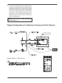
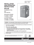
Piping Configurations for Raytherm Commercial Pool Heaters
INTERNAL DIVERTING
BYPASS SYSTEM (UG)
4 PIPE
DIAMETERS
MAX.
Models 0926 thru 1223 with UG
15
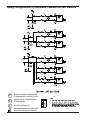
Piping Configurations for Raytherm Commercial Pool Heaters
4 PIPE
DIAMETERS
MAX.
4 PIPE
DIAMETERS
MAX.
4 PIPE
DIAMETERS
MAX.
TI
BLENDED WATER TEMPERATURE
(THERMOMETER AT HEATER INLET)
To
HEATER OUTLET TEMPERATURE
THERMOMETER
Tc
HEATER THERMOSTAT
RECOMMENDED FIELD INSTALLED
ISOLATION VALVES FOR SERVICE
16
Piping Configurations for Raytherm Commercial Pool Heaters
4 PIPE
DIAMETERS
MAX.
4 PIPE
DIAMETERS
MAX.
4 PIPE
DIAMETERS
MAX.
Models 2100 thru 4001
TI
BLENDED WATER TEMPERATURE
(THERMOMETER AT HEATER INLET)
To
HEATER OUTLET TEMPERATURE
THERMOMETER
Tc
HEATER THERMOSTAT
RECOMMENDED FIELD INSTALLED
ISOLATION VALVES FOR SERVICE
17
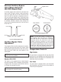
External Auxiliary Bypass
Valve (Where Required)
926-1223 Models Only
Bypass Valve
An auxiliary bypass valve should be used when flow
rates exceed 100 gpm (usually a high performance
pump size larger than two HP will exceed this flow
rate). This valve is required to complement the function of the automatic bypass valve, particularly when
starting the heater in winter or early spring when the
spa or pool temperature is below 55°F. It also serves
to eliminate needless pressure drop through the
heater and accompanying reduction in the flow rate to
the spa jets, etc.
From Heater
Open Position
Closed Position
To Heater
Fig. 24: Manual Bypass Valve
From Filter
To Pool
NOTE: To avoid water damage or scalding due to
valve operation, drain pipe must be connected to
valve outlet and run to a safe place of discharge.
Drain pipe must be the same size as the valve
discharge connection throughout its entire length
and must pitch downward from the valve. No shut-off
valve shall be installed between the relief valve and
the drain line. Valve lever should be tripped at least
once a year to ensure that waterways are clear.
Fig. 23: Auxiliary Bypass Valve
Auxiliary Bypass Valve
Adjustment
To set bypass: With clean filter, adjustment is made by
feeling the inlet and outlet pipes at the heater. Outlet
pipes should be slightly warmer than inlet and comfortable to the touch. If pipe is hot, close bypass; if cold,
open bypass.
Temperature Controls
High Limits
NOTE: Do not use a gate valve as an auxiliary
bypass valve on any heaters.
The pool heater is equipped with two high limits. Both
high limits, the non-adjustable auto reset high limit and
adjustable manual reset high limit are attached to the
outlet side of the in/out header.
Models 926-1223
Pool Stat
The heater is also equipped with a manual bypass
built into the header. This is in addition to the automatic bypass valve. This may be used with flow rates up
to 100 gpm and adjusted as below.
The pool heater is equipped with a pool thermostat
that is attached to the inlet side of the in/out header to
control the pool temperature.
NOTE: Sooting or liming caused by improper
bypass adjustment voids the warranty.
18
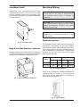
Low Water Cutoff
Electrical Wiring
Automatically shuts down burner whenever water
level drops below probe. A 3 to 5 second time delay
prevents premature lockout due to temporary conditions such as power failure or air pockets. Standard on
Cal Code heaters.
DANGER - SHOCK HAZARD - Make sure
electrical power to the heater is disconnected to
avoid potential serious injury or damage to
components.
CAUTION: Label all wires prior to disconnection
when servicing controls. Wiring errors can cause
improper and dangerous operation. Verify proper
operation after servicing.
NOTE: If it is necessary to replace any of the
original wiring, it must be replaced with 105° C wire
or its equivalent.
Electronic Ignition
Fig. 25: Low Water Cutoff
The intermittent ignition device conserves energy by
automatically extinguishing the pilot when desired
temperature is reached. When additional heat is needed, the pilot re-ignites electrically, eliminating the fuel
costs of maintaining a constant pilot. To ensure safe
operation, the gas valve cannot open until the pilot
relights and is confirmed.
High & Low Gas Pressure Switches
Pressure switches sense either high or low gas pressure and automatically shut down burners if abnormal
pressures exist. Standard on Models 3001-4001.
Model
Without Lockout
With Lockout
N
P
N
P
926–1826
Standard
N/A
Optional
Standard
2100–4001
N/A
N/A
Standard
Standard
Table E: Lockout Availability
Heater must be electrically grounded and bonded in
accordance with local codes, or, in the absence of
local codes, with the latest edition of the National
Electrical Code, ANSI/NFPA 70.
Fig. 26: High/Low Gas Pressure Switch
Fig. 27: Ignition Module
19
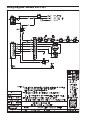
Wiring Diagram—Models 926–1223
20
Wiring Diagram—Models 1287–1826
21
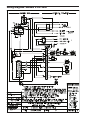
Wiring Diagram—Models 2100–2500
22
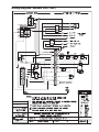
Wiring Diagram—Models 3001–4001
23
SERVICING
Temperature Control
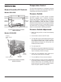
General Location Of Controls
The pool water temperature is controlled by the pool
thermostat. The heater water temperature high limit is
controlled by the manual reset high limit.
Models 926-1826
Pressure Switch
Inlet/Outlet
Header
Pressure
Switch
Unitherm
Governor
Electrical
Conn.
Hi-limit
control/
T e mp . C o n t ro l
The pressure switch, or heater actuator on Models
926-1223 equipped with a Unitherm Governor,
ensures that the heater operates only when the filter
pump is in operation. It is factory set at 1.75 PSI for
deck level installations. When the heater is located
below the level of the spa or pool, it may be necessary
to reset the pressure switch to compensate for the noflow static head. If it is necessary to reset the pressure
switch, we recommend the following procedure.
Main Burner Gas Valve
Pressure Switch Adjustment
Fig. 28: General Location of Controls
(Models 926-1826)
1. Make sure the pool filter is clean before adjusting
the switch.
Models 2100-4001
2. Set the heater control to the OFF mode.
Inlet/Outlet
Header w/Bypass
Pump
3. Turn the filter pump on and confirm that the pressure switch is closed (use a multimeter to check).
If the pressure switch fails to close, either the
switch setting is too high or the filter pump is not
supplying enough pressure.
4. Turn the heater ON.
5. Manually turn the pressure adjustment knob clockwise until the heater shuts off. (A flat screw driver
may be necessary if knob is too tight).
6. Slowly turn the adjustment knob counter-clockwise until the heater calls for heat again.
Electrical
Connection
Manual On/Off Valve
Main Burner
Gas Valve
7. Turn an additional 1/2 turn counter-clockwise.
8. While the heater is running, check the adjustment
by turning the pump off and on several times. The
burners should shut off immediately when the
pump is turned off. If it does not, repeat the above
steps until proper operation is observed.
Fig. 29: General Location of Controls
(Models 2100-4001)
24
START-UP
PROCEDURES
Before Start-Up
Burners
Clean main burners and air louvers of dust, lint and
debris. Keep heater area clear and free from combustibles, flammable liquids, and chemicals. Do not
obstruct the flow of combustion and ventilating air.
ADJUSTMENT KNOB
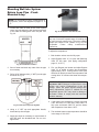
Water
Fig. 30: Pressure Switch Adjustment Range
Water must be flowing through the heater.
Start-Up
5’ Max
CAUTION: Propane gas is heavier than air and
sinks to the ground. Exercise extreme care in lighting
heater in confined areas.
5’ Max
Lighting Instructions
Fig. 31: Heat Exchanger Height Above/Below Pool
1. Close all gas valves. Turn off electric power supply
wait 5 minutes.
NOTE: If heater is installed outside of the limits
shown, a flow switch must be used in place of the
pressure switch when mounted and wired adjacent
to the heater.
2. Open manual pilot valve. Turn on electric power,
pilot is automatically lighted.
3. Open main gas valve.
Two-Speed Pumps
4. Set temperature controls to desired temperature.
To Shut Down
In some cases, the flow on the low speed is insufficient
to operate the heater. This is apparent when the pressure switch cannot be further adjusted or if the heater
makes banging noises. In these cases, the pump must
be run at high speed when heating the water.
Close all manual gas valves. Turn off electric power.
CAUTION: Do not operate the heater without the
function of a properly adjusted pressure switch.
Pilot Safety
The heater employs a pilot safety which closes the
main gas valve within 8/10ths of a second whenever
the pilot flame is interrupted. Pilot flame is automatically lit when the device is powered. Unit performs its own
safety check and opens the main valve only after the
pilot is proven to be lit.
25
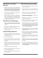
INSPECTION
PROCEDURES
After Start-Up
Pilot System Checkout Procedure
Burners
1. Turn on power to the ignition systems and turn gas
supply off.
Clean main burners and air louvers of dust, lint and
debris. Keep heater area clear and free from combustibles and flammable liquids. Do not obstruct the
flow of combustion and ventilating air. Make visual
check of burner and pilot flame. Yellow flame indicates
clogging of air openings. Lifting or blowing flame indicates high gas pressure. Low flame indicates low gas
pressure.
2. Check ignition module as follows:
a. Set the thermostat above pool water temperature to turn heater on.
b. Watch for continuous spark at the pilot burner.
c.
Time the spark operation. Time must be within the lockout timing period (15 or 90
seconds).
d. Turn thermostat down to turn off heater and
wait 60 seconds on lockout models before
beginning step 3.
3. Turn on gas supply.
4. Set thermostat above pool water temperature to
turn on heater.
Fig. 32: Main Burner Flame
5. Systems should start as follows:
a. Spark will turn on and pilot gas valve will open
at once. Pilot burner should ignite after gas
reaches the pilot burner.
b. Spark ignition should cut off when pilot flame
is established.
c.
Main gas valve should open and main burner
should ignite after gas reaches the burner
port.
Fig. 33: Pilot Burner Flame
Feel inlet and outlet pipes. Outlet should be only slightly warmer than inlet. It should not be hot.
WARNING: Should overheating occur or the gas
supply fails to shut off, turn off the manual gas
control to the appliance.
CONTROLS
Check all controls to see that they are operational. To
check electric safety turn off main burner. Observe
pilot burner when shutting off pilot gas. Ignition spark
should go on. Main gas valve will also drop out.
26
SERVICING
PROCEDURES
Burner Drawer Removal
Tube Cleaning Procedure
(Typical)
Establish a regular inspection schedule, the frequency
depending on the local water condition and severity of
service. Do not let the tubes clog up solidly. Clean out
deposits over 1/16" in thickness.
1.
Shut off power and gas supply to the pool heater.
Disconnect union(s) and pilot tubing, then loosen
and remove burner-hold down screws.
2.
Disconnect wires at gas valve and slide burner
drawer out.
Gas Valve Removal
1. Shut off gas supply to the pool heater. Remove
gas piping to gas valve inlet.
Although the illustration shows the mechanical cleaning procedure of a small heater, it is typical of all sizes.
The heater may be cleaned from the return header
side as shown, without breaking pipe connections. It is
preferable, however, to remove both headers for better visibility through the tubes and to be sure the
ground up lime dust does not get into the system.
2. Disconnect wires, pilot tubing and bleed line, if
required.
3. Turn vertical gas pipe from manifold slightly and
unscrew gas valve.
4. Reverse above procedure to re-install.
Note that you do not remove the top pan or the heat
exchanger, generally.
After reaming, mount the wire brush in lieu of the
auger and clean out the debris remaining in the tubes.
Another method is to remove the heat exchanger,
ream tubes and immerse heat exchanger in non-inhibited de-scale solvent.
RAYPAK TUBE CLEANING KIT
Extension Pieces (5)
Auger with Carbide Tip
Fig. 34: Tube Cleaning Kit
Fig. 35: Tube Cleaning Procedure
27
Wire Brush
F
Main Burner and Orifice
Removal
Heat Exchanger Reassembly
1. Heat exchanger header O-rings should be
replaced with new ones.
1. Remove screws and burner hold down bracket.
NOTE: If the heat exchanger is sooted badly, the
burner hold-down bracket and spacer can become
distorted from direct flame impingement and this
usually necessitates replacement of these parts.
2. Install inlet-outlet and return water headers and
install header retainer nuts and torque nuts evenly.
2. Lift burners from slotted spacer and slide from orifices. Clean with a wire brush.
3. Install the four (4) corner clips between tube
sheets and refractory. Replace "V" baffles.
3. Orifices usually do not need to be replaced. To
clean, run either copper wire or wood through orifice. Do not enlarge hole. To remove orifice, use a
socket wrench and remove the manifold. DO NOT
overtighten when reinstalling.
4. Install thermostat sensing bulbs in header wells
and replace bulb retaining clips.
Pilot Removal and Cleaning
6. Install water pressure relief valve, flow switch, and
low water cutoff devices if so equipped.
1. Disconnect pilot tubing at pilot and sensor/igniter
wire. Remove screws holding pilot bracket to burner drawer.
7. Open water supply and return shutoff valves. Fill
heater and water piping system with water. Check
heater and piping system for leaks at full line pressure. Run system circulating pump for a minimum
of 1/2 hour with heater shutoff.
5. Install inlet and return pipes in water headers
using pipe thread sealant.
2. Remove pilot and bracket, clean pilot of debris,
small bugs, etc., with wire or small brush.
8. Shut down entire system and vent all radiation
units and high points in system piping. Check all
strainers for debris.
3. Replace pilot, pilot tubing, sensor ignition wires
and check for leaks.
Heat Exchanger Removal
9. Install flue collector, jacket top and inspection panels. Install top holding screws. Install draft diverter
and vent piping if so equipped.
1. Shut water, gas and electricity off, close valves,
relieve pressure and remove relief valve. Remove
side inspection panels.
2. Remove top holding screws.
10. If gas piping was disconnected, reconnect gas piping system and check for leakage using a soap
solution.
3. Remove draft diverter, lift and remove top and flue
collector on stack type models. Remove inspection panels.
11. Double check electrical circuits, grounding connections and pump with wiring diagram supplied
with heater.
4. Loosen bolts and disconnect flange nuts on
inlet/outlet header, loosen union(s) at gas pipe,
and slide heater away from piping until studs clear
the heater.
12. Check for correct water pressure and water level
in the system. Make sure that system pump operates immediately on the call for heat. The system
is ready for operation.
5. Remove heat exchanger corner brackets.
6. Remove combustion chamber clips at the four corners of the heat exchanger.
7. Lift heat exchanger straight up using caution not to
damage refractory.
28
Combustion Chamber Removal
canopy and flue collector off (on models 926-1826,
remove the canopy hold-down brackets). Remove "V"
baffles over tube(s) to be replaced. If no pipe unions
have been provided, use the header as a union,
remove the flange nuts off the inlet-outlet header,
break gas connection and slide heater away from piping, allowing room to work. Pull wedge clips out of
control wells and remove sensing bulbs. Remove
flange nuts from the return header and remove header. Lift heat exchanger straight up and out.
To remove the combustion chamber you must first
have removed the heat exchanger. Unbolt metal combustion chamber retainer from top and remove
combustion chamber panels individually.
Heat exchanger header o-rings must be replaced with
new ones. The tube may be cut out with a hack-saw or
hammer and chisel adjacent to both tube sheets, leaving stubs in the tube sheets. Then proceed to collapse
stubs in the tube sheets with a chisel or screwdriver.
Use caution not to cut into the tube sheet.
Replacement tubes will have the fins stripped off
longer on one end. The long end is inserted into the
opening of the tube sheet first; then the short end is fitted through the opposite tube sheet. If the tube ends
become dented or bent, straighten at least four (4)
inches back from the tube end by means of a tapered
punch.
Fig. 36: Refractory Panels—Top View
Control Well Replacement
Remove top, sensing bulb and clip. Collapse well tube
at the open end and with a chisel, push through into
the header, and remove the well through header.
Insert a new well and roll into place. If a roller is not
available, solder the well in place with silver solder.
Insert tube roller into tube opening up to stop against
tube, then push center rod in until roller is tight. Be
careful to keep replacement tube squared up 1/8" outside each tube sheet. A loose tube will sometimes pull
toward the roller. Attach drill motor to tube roller, holding it straight and level. Proceed to expand tube until
the tool begins to grab. At this point, 1/2" to 1" should
be exposed on the tool shank. Reverse drill motor or
wrench out by hand. Care should be exercised to
avoid applying excessive torque during rolling operation and to avoid thinning out any part of the tube wall
excessively over .015". Use same procedure at the
opposite end of the tube.
Immersion Well
Fig. 37: Immersion Well
Apply line pressure test, and re-roll, if necessary,
before replacing canopy.
Tube Replacement Procedure
Procedure For Cleaning Flue
Gas Passageways
On Raypak tube replacement may be affected without
rolling, as a temporary means of repair, provided there
are two or more tubes rolled into act as stays on left
and right sides. The "O" rings should provide a seal up
to 125 PSI working pressure. Use a 3/8" heavy duty
reversible drill motor or larger, to power the tube roller.
If a reversible drill is not available, after rolling the tube
in, remove the drill motor and wrench out the roller. A
tube roller is available from the factory.
Soot can clog areas behind fins and cause eventual
tube failure. Any sign of soot at base of burners or
around outer jacket indicates a need for cleaning.
1. Lift off draft hood and flue collector by removing
bolts and screws.
2. Remove "V" baffles from heat exchanger.
Shut gas and power off to the unit, close the system off
and drain the pool heater. Remove draft diverter.
Remove the access panels and jacket top. Lift the
3. Remove burner tray.
29
MAINTENANCE AND
CARE
4. Take garden hose and wash heat exchanger, making sure soot is removed from between fins. (Avoid
excessive water against refractory).
5. Reassemble; when heater is fired, some steam will
form from wet refractory. This is normal.
To be followed one month after initial start-up and then
quarterly.
NOTE: In extreme cases it may be necessary to
remove the heat exchanger completely for cleaning.
The simplest method is steam cleaning at a local car
wash. DO NOT WIRE BRUSH!
1. Inspect top of heater and draft-hood for soot, and
open fuel gas passageways.
2. Clean main burners and pilot burner of dust and
lint.
CAUTION: Soot is combustible, so exercise
extreme care.
CAUTION: Soot may be combustible. Wet completely when cleaning.
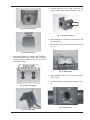
Unitherm Governor
Replacement
3. Inspect and operate all controls and gas valve.
4. Make visual check of burner and pilot flame.
Flame pattern on main burner and pilot is indicated on page 26. Yellow flame means restriction of
air openings. Lifting or blowing flame indicates
high gas pressure. Low flame means low gas
pressure.
1. Shut off water, gas and electricity, close valves,
relieve pressure.
2. Drain heat exchanger.
3. Remove Unitherm Governor.
5. Clean room air intake openings to ensure adequate flow of combustion and ventilation air.
INLET/OUTLET HEADER
6. Remove header opposite inlet pipes when cleaning and inspect internal tubes for scale deposits. If
scale does not form within first quarterly inspection, then inspect annually thereafter.
OUTLET
INLET
CAUTION: Combustion air must not be
contaminated by corrosive chemical fumes which
can damage the heater and void the warranty.
GASKET
UNITHERM GOVERNOR
WITH POWER ELEMENT
7. Keep heater air clear and free from combustible
materials and other flammable and corrosive
vapors and liquids.
Fig. 38: Unitherm Governor—Models 926–1223
To test operation of Unitherm Governor, place in hot
water (110°F or higher) and watch for movement
against spring. If no movement, replace.
8. Keep moving parts lubricated.
9. Manual operation of pressure/temperature relief
valve at least once a year.
30
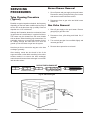
Winterizing Your Heater
When heaters installed outdoors in freezing climate
areas are to be shut down for the winter, please
observe the following step-by-step procedure:
1. Remove the drain plug or open the drain cock
located on the inlet-outlet header. On larger
heaters with external Unitherm Governor(s) and
piping, locate plug at low point of Governor piping,
or break connections and rotate inlet fittings 180
degrees to face downward. Turn off manual main
gas and main gas shut off.
2. On units equipped with a UG (models 926-1223),
locate the pressure switch. Disconnect the compression fittings on both ends of the 1/8" copper
tube and allow the tube to drain. Remove the "heat
exchanger inspection panels" on the right side of
the heater to gain access to the fitting on the
return header. Remove the return header to
ensure that no water remains in the heat exchanger.
31
TROUBLESHOOTING
IMPORTANT NOTICE
These instructions are primarily intended for the use of qualified personnel specifically trained and experienced
in the installation of this type of heating equipment and related system components. Installation and service
personnel may be required by some states to be licensed. Persons not qualified shall not attempt to install this
equipment nor attempt repairs according to these instructions.
MECHANICAL (FOR QUALIFIED SERVICE PERSONNEL ONLY)
PROBLEM
CAUSE
SOLUTION
Harmonics, or whining noise
U.G. Inoperative……………………
Check movement by putting in hot
water (110°F or higher). If no movement, replace.
Locate the restriction and remove.
Flush system and clean.
Remove debris or blow out gas line.
Scale forming in heat exchanger clean heat exchanger and check
pool pH and total alkalinity.
*Debris or restriction in system……
*Debris in gas line…………………..
Low flow……………………………...
Heater going on and off
continously
Dirty filter……………………………
Low water level in pool..……………
External bypass setting out of
adjustment…………………………..
*Pressure switch out of
adjustment…………………………..
Backwash filter.
Raise water level.
Liming or scale forming on
heat exchanger
Pool water…………………………....
Recommended pH should be between 7.3 and 7.8 total alkalinity 100150 PPM maximum. Hardness -150400 PPM maximum. (see page 2)
Sooting
High flow rates…………………….....
Reduce by adding manual bypass
valve and adjust by putting thermometer in header (1/4" NPT) drain
opening. Set bypass so thermometer reads between 105° and 110°F.
Check movement by putting in hot
water (110°F or higher). If no movement, replace.
Refer to installation instructions.
Follow recommended installation
instructions.
U.G. Inoperative……………………..
*Air starvation………………………..
*Improper venting…………………....
Adjust bypass
Adjust pressure switch
*Insects or debris clogging
burner intake ports…………………..
Clean burners
Pilot outage
Low gas pressure…………………....
Restricted pilot……………………....
Weak pilot generator………………..
Adjust gas pressure.
Clean pilot.
Replace pilot.
Yellow lazy flame
Low gas pressure…………………....
*Insects or debris clogging
burner intake ports…………………..
Adjust gas pressure.
Clean burners.
*Usually occurs on initial start-up
32
Outer jacket very hot
(paint blistered)
Takes long time to heat pool
or spa
*Broken refractory caused by
shipping damage or improper
combustion…………………………..
Excessive sooting of heat
exchanger…………………………...
Calculate temperature in °F/hr……...
Filter not running long enough……....
Dirty filter……………………………..
Gas line or meter undersized………..................................
Replace refractory panels.
Determine cause of sooting &
correct.
Heat rise (°F/hr.) = Htr.output
Pool gallonage x 8.33
or refer to heater sizing chart.
This does not take into account heat
loss due to weather.
Reset time clock.
Clean filter.
Refer to installation instructions.
Liming
Bypassing too much water………....
U/G not functioning……………….....
Leaking at well.
Leaking at heat exchanger.
Gasket brittle and leaking(overheated).
Overacid…………………………......
Overacid……………………………...
Heater running after pump
shuts off……………………………...
Refractory damage………………….
Sooted heater………………………..
*Usually occurs on initial start-up
33
Inspect bypass for movement, if no
movement, replace.
Replace if no movement when
heated.
Replace well and maintain water
chemistry properly.
Replace heat exchanger and maintain chemistry properly.
See pressure switch adjustment.
Replace refractory.
Determine cause of sooting and correct.
ELECTRICAL (ELECTRONIC IGNITION IID) IID
WARNING: HIGH VOLTAGE.
technicians ONLY.
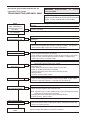
Intermittent Pilot System
TROUBLESHOOTING HONEYWELL S8600
START
TURN GAS SUPPLY OFF.
TURN THERMOSTAT
(CONTROLLER) TO CALL
FOR HEAT
POWER TO MODULE
(24 V NOMINAL)
YES
SPARK ACROSS
IGNITER/SENSOR GAP
YES
For
qualified
NOTE: Some heaters may be equipped with an
ignition module that shuts off pilot gas if the pilot fails
to light. To reset, interrupt power to the heater.
NOTE: Before troubleshooting, familiarize yourself with the start-up and checkout
procedure.
NO
Check line voltage power, low voltage transformer, limit controller, thermostat
(controller) and wiring.
Pull ignition lead and check spark at module.
NO
Spark Okay?
YES
• Check ignition cable, ground wiring, ceramic insulator and gap, and correct.
• Check boot of the ignition cable for signs of melting or buckling. Take protective
action to shield cable and boot from excessive temperatures.
TURN GAS SUPPLY ON
PILOT BURNER LIGHTS?
YES
NO
SPARK STOPS WHEN
PILOT IS LIT?
YES
NO
MAIN BURNER LIGHTS?
YES
NO
SYSTEM RUNS UNTIL
CALL FOR HEAT ENDS?
YES
NO
• Check that all manual gas valves are open, supply tubing and pressures are
good, and pilot burner orifice is not blocked.
• Check electrical connections between module and pilot operator on gas control.
• Check for 24 Vac across PV-MV/PV terminals on module. If voltage is okay,
replace gas control; if not, replace module.
NOTE: If S8600H goes into lockout, reset system by removing power for at least
60 seconds. Lockout is used on Pro. models.
• Check continuity of ignition cable and ground wire.
• Clean flame rod.
• Check electrical connections between flame rod and module.
• Check for cracked ceramic flame rod insulator.
• Check that pilot flame covers flame rod and is steady and blue.
• Adjust pilot flame.
• If problem persists, replace module.
• Check for 24 Vac across MV-MV/PV terminals. If no voltage, replace module.
• Check electrical connections between module and gas control. If okay, replace
gas valve or gas control operator, i.e. pilot gas valve, flow switch etc.
NOTE: IF S8600H goes into lockout, reset system.
• Check continuity of ignition cable and ground wire.
NOTE: If ground is poor or erratic, shutdowns may occur occasionally even though
operation is normal at the time of checkout.
• Check that pilot flame covers flame rod and is steady and blue.
• If checks are okay, replace module.
CALL FOR HEAT ENDS
SYSTEM SHUTS OFF?
YES
TROUBLESHOOTING
ENDS
NO
• Check for proper thermostat (controller) operation.
• Remove MV lead at module; if valve closes, recheck temperature controller and
wiring; if not, replace gas valve.
Repeat procedure until trouble free operation is obtained.
34
RAYTHERM COMMERCIAL SWIMMING POOL HEATERS
LIMITED WARRANTY
RAYTHERM TYPE P
SIZES 0926-4001
SCOPE:
Raypak, Inc. ("Raypak") warrants to the original owner that all parts of this boiler which are actually manufactured by Raypak will
be free from failure under normal use and service for the specified warranty periods and subject to the conditions set forth in this
Warranty. Labor charges and other costs for parts removal or reinstallation, shipping and transportation are not covered by this Warranty
but are the owner's responsibility.
HEAT EXCHANGER WARRANTY:
Five (5) years from date of boiler installation. Includes only cupro nickel heat exchanger with bronze waterways.
ANY OTHER PART MANUFACTURED OR FURNISHED BY RAYPAK:
One (1) Year warranty from date of boiler installation, or eighteen (18) months from date of factory shipment based on Raypak's
records, whichever comes first.
SATISFACTORY PROOF OF INSTALLATION DATE, SUCH AS INSTALLER INVOICE, IS REQUIRED. THIS WARRANTY WILL BE
VOID IF THE BOILER RATING PLATE IS ALTERED OR REMOVED.
ADDITIONAL WARRANTY EXCLUSIONS:
This warranty does not cover failures or malfunctions resulting from:
1. Failure to properly install, operate or maintain the boiler in accordance with our printed instructions provided;
2. Abuse, alteration, accident, fire, flood and the like;
3. Sediment or lime buildup, freezing, or other conditions causing inadequate water circulation;
4. High velocity flow exceeding boiler design rates;
5. Failure of connected systems devices, such as pump or controller;
6. Use of non-factory authorized accessories or other components in conjunction with the boiler system;
7. Chemical contamination of combustion air or use of chemical additives to water.
8. Misuse or neglect, including but not limited to freeze ups, and operating the heater with cabinet door off, having flow
restrictions or obstructions between the heater outlet and pool/spa or not maintaining proper thermal balance. pH level must be
between 7.3 and 7.8 and total alkalinity between 100 and 150 PPM. Total Dissolved Solids (TDS) must be no greater and 3000
PPM, depending on pool/spa construction. (See page 2 of the I&O Manual for water chemistry information.)
PARTS REPLACEMENT:
Under this Warranty, Raypak will furnish a replacement for any failed part. The failed part must first be returned to Raypak if requested, with transportation charges prepaid, and all applicable warranty conditions found satisfied. The replacement part will be warranted
for only the unexpired portion of the original warranty. Raypak makes no warranty whatsoever on parts not manufactured by it, but
Raypak will apply any such warranty as may be provided to it by the parts manufacturer.
TO MAKE WARRANTY CLAIM:
Promptly notify the original installer, supplying the model and serial numbers of the unit, date of installation and description of the
problem. The installer must then notify his Raypak distributor for instructions regarding the claim. If either is not available, contact Service
Manager, Raypak, Inc., 2151 Eastman Ave, Oxnard, CA 93030 or call (805) 278-5300. In all cases proper authorization must first be
received from Raypak before replacement of any part.
EXCLUSIVE WARRANTY - LIMITATION OF LIABILITY:
This is the only warranty given by Raypak. No one is authorized to make any other warranties on Raypak's behalf. THIS WARRANTY IN LIEU OF ALL OTHER WARRANTIES, EXPRESS OR IMPLIED, INCLUDING BUT NOT LIMITED TO IMPLIED WARRANTIES OF
MERCHANTABILITY AND FITNESS FOR A PARTICULAR PURPOSE. RAYPAK'S SOLE LIABILITY AND THE SOLE REMEDY
AGAINST RAYPAK WITH RESPEC TO DEFECTIVE PARTS SHALL BE AS PROVIDED IN THIS WARRANTY. IT IS AGREED THAT
RAYPAK SHALL HAVE NO LIABILITY, WHETHER UNDER THIS WARRANTY, OR IN CONTRACT, TORT, NEGLIGENCE OR OTHERWISE, FOR ANY SPECIAL, CONSEQUENTIAL, OR INCIDENTAL DAMAGE, INCLUDING DAMAGE FROM WATER LEAKAGE. Some
states do not allow limitations on how long an implied warranty lasts, or for the exclusion of incidental or consequential damages. So the
above limitation or exclusion may not apply to you.
This Limited Warranty gives you specific legal rights. You may also have other rights which may vary from state to state. We suggest that you complete the information below and retain this certificate in the event warranty service is needed. Reasonable proof of the
effective date of the warranty (date of installation) must be presented, otherwise, the effective date will be based on the rate of manufacture plus thirty (30) days.
Effective: 04-15-2007
Replaces: 07-01-92
35
www.raypak.com
Raypak, Inc., 2151 Eastman Avenue, Oxnard, CA 93030 (805) 278-5300 Fax (805) 278-5468
Litho in U.S.A.
36